Vecima Networks EUM3003 Wireless LAN end-user modem User Manual LMS4000 900 MHz Guide
Vecima Networks Inc. Wireless LAN end-user modem LMS4000 900 MHz Guide
UserManual.wiki
>
Vecima Networks
>
EUM3003 User Manual
>
Users Manual
Contents
1.
Warning and Notices
2.
Users Manual
Users Manual
Navigation menu
Upload a User Manual
Namespaces
Wiki Guide
HTML
PDF
Info
Views
User Manual
Discussion / Help
Navigation
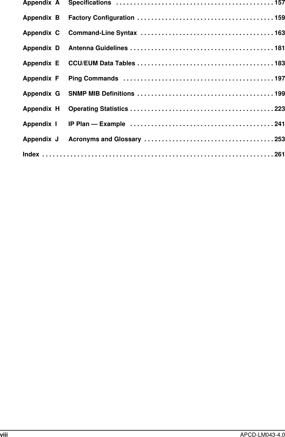
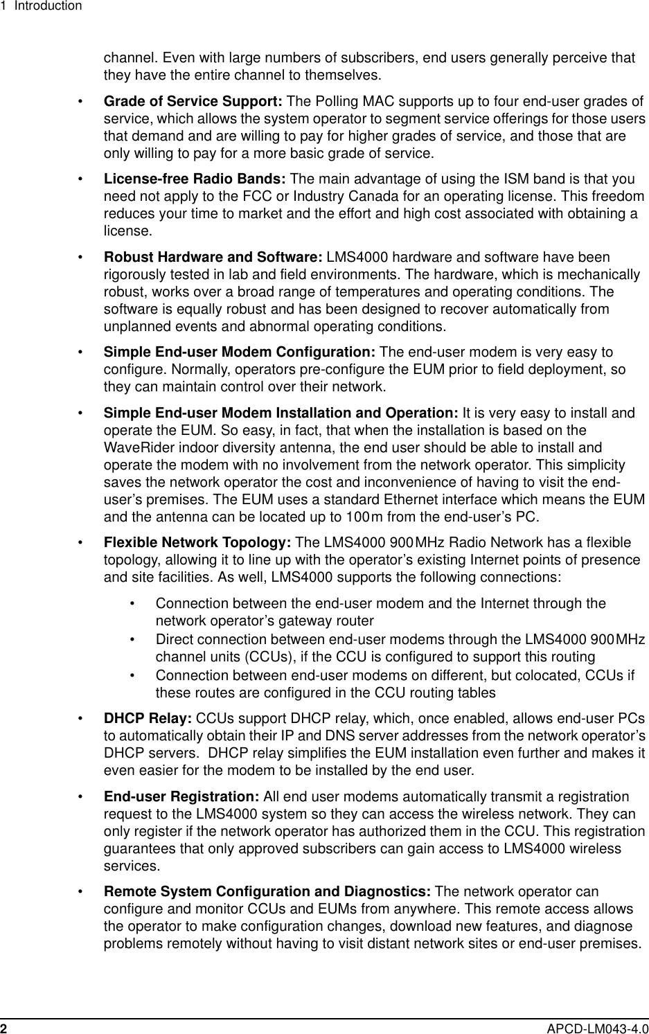

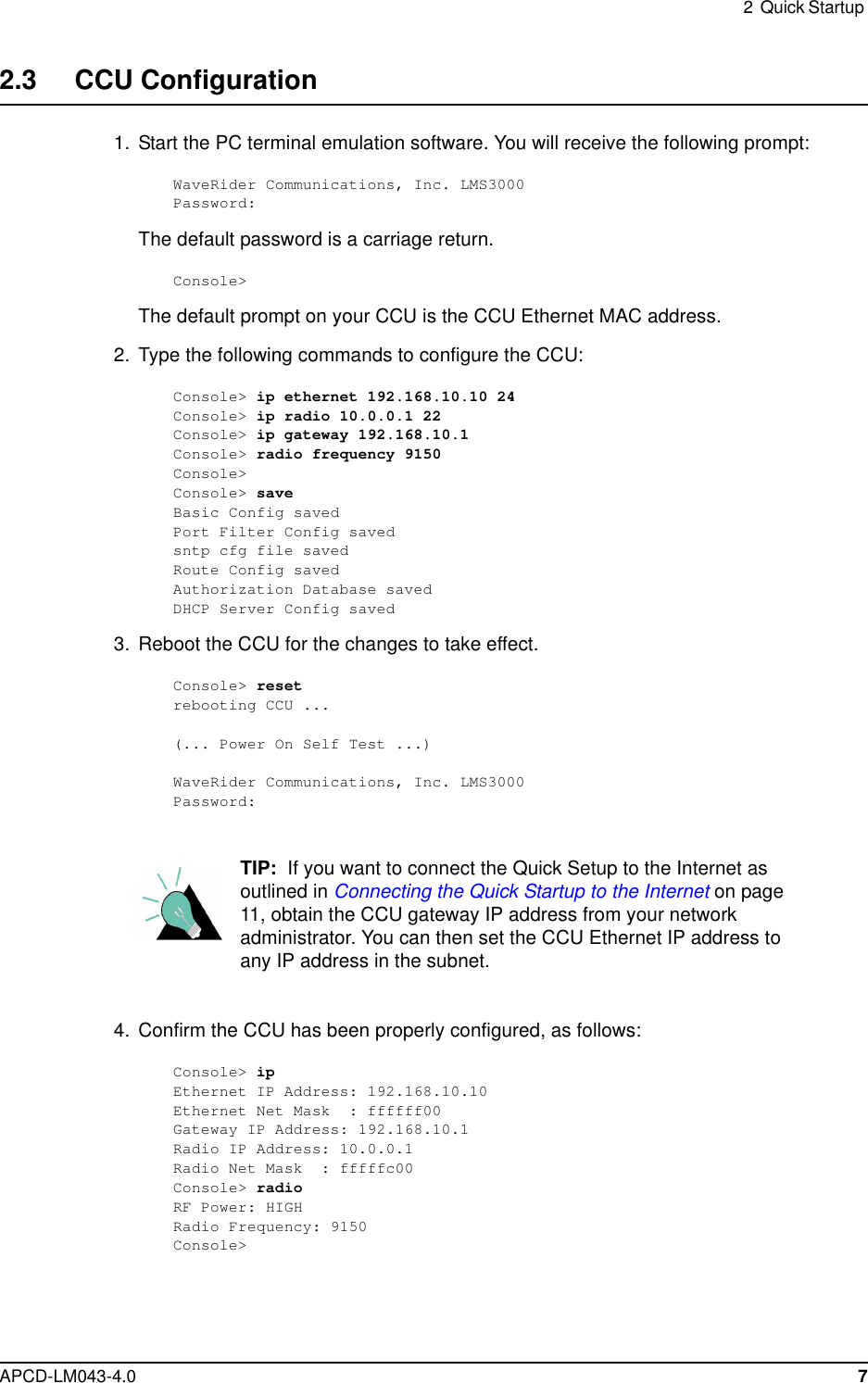
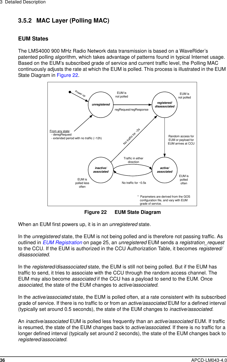
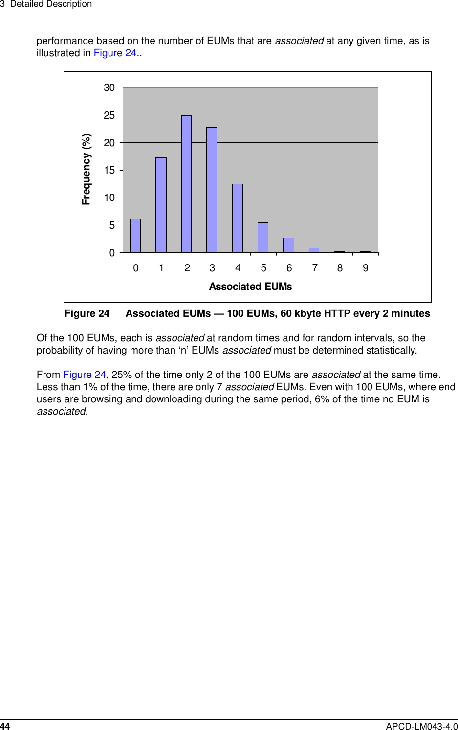
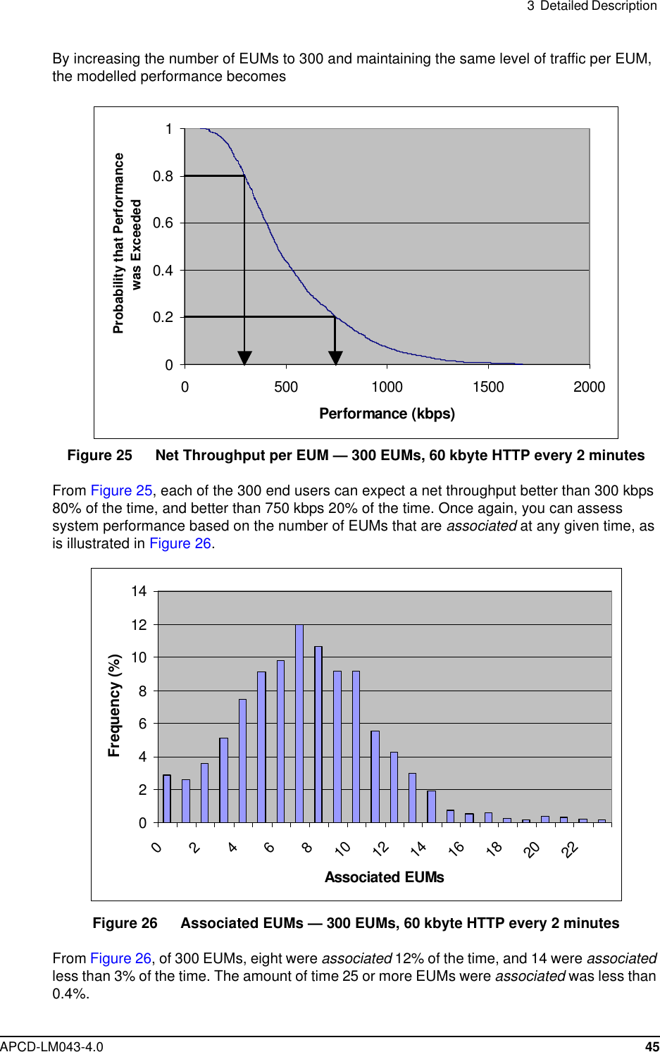
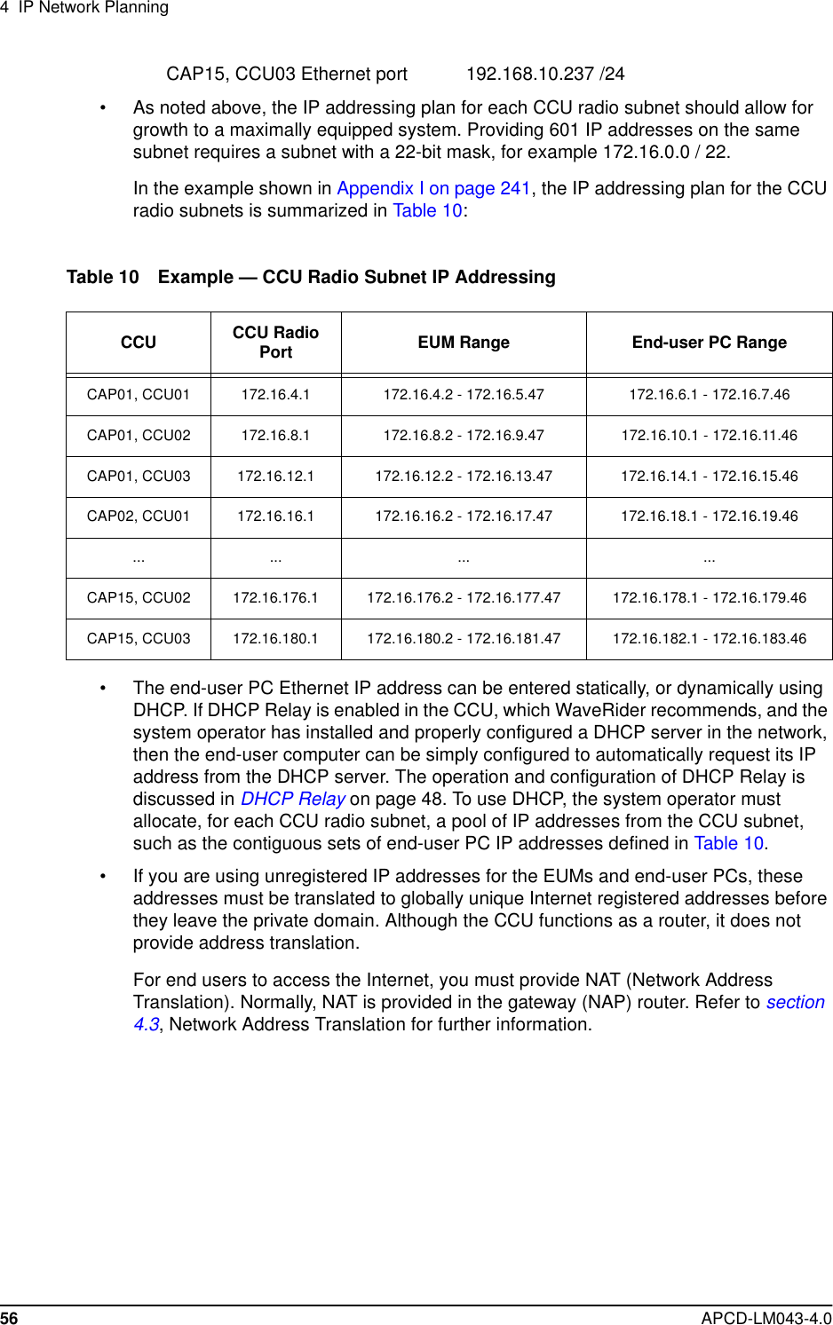
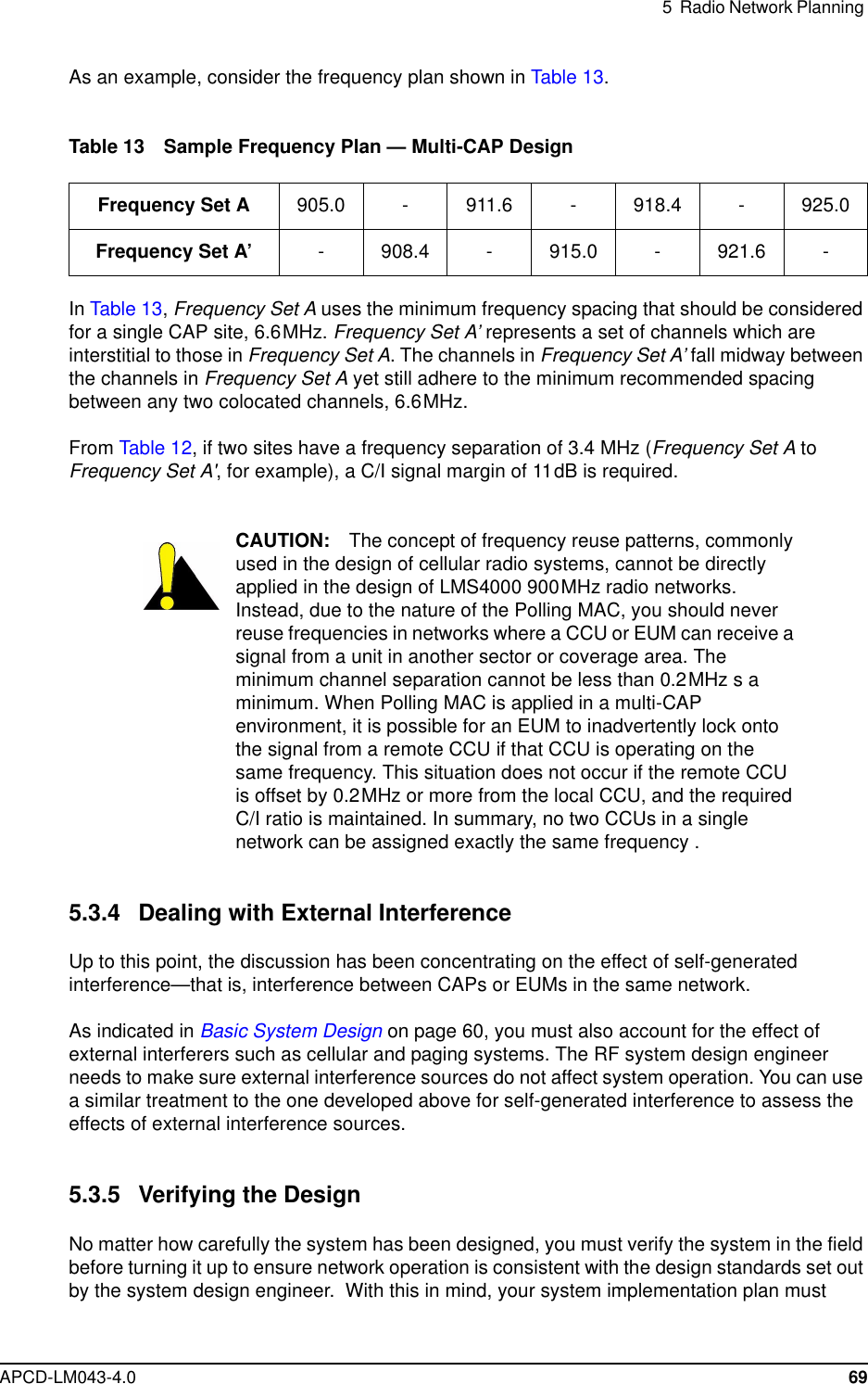
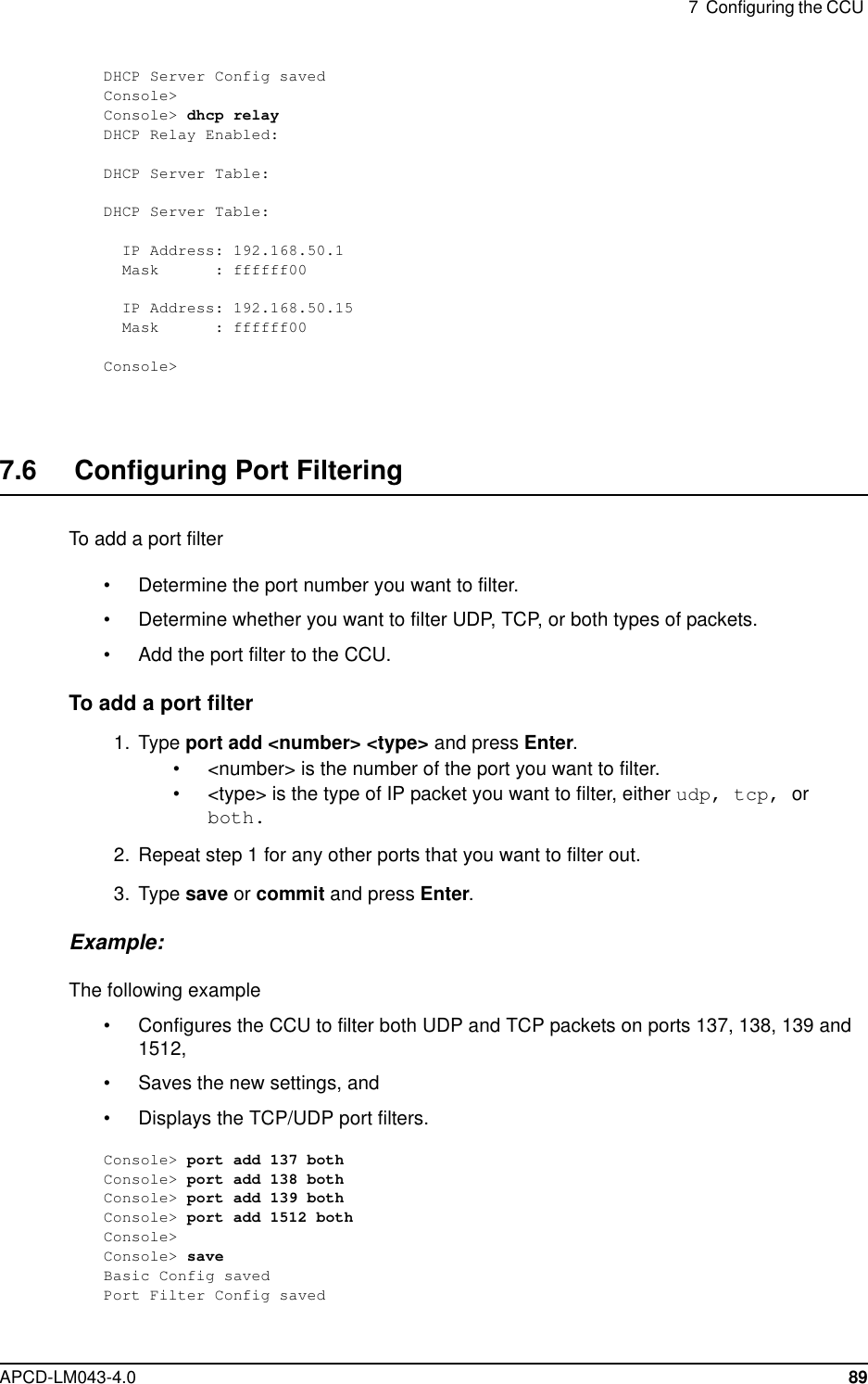
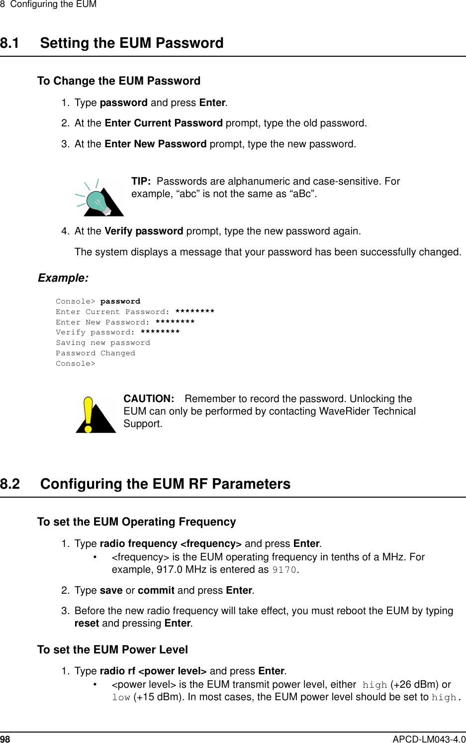
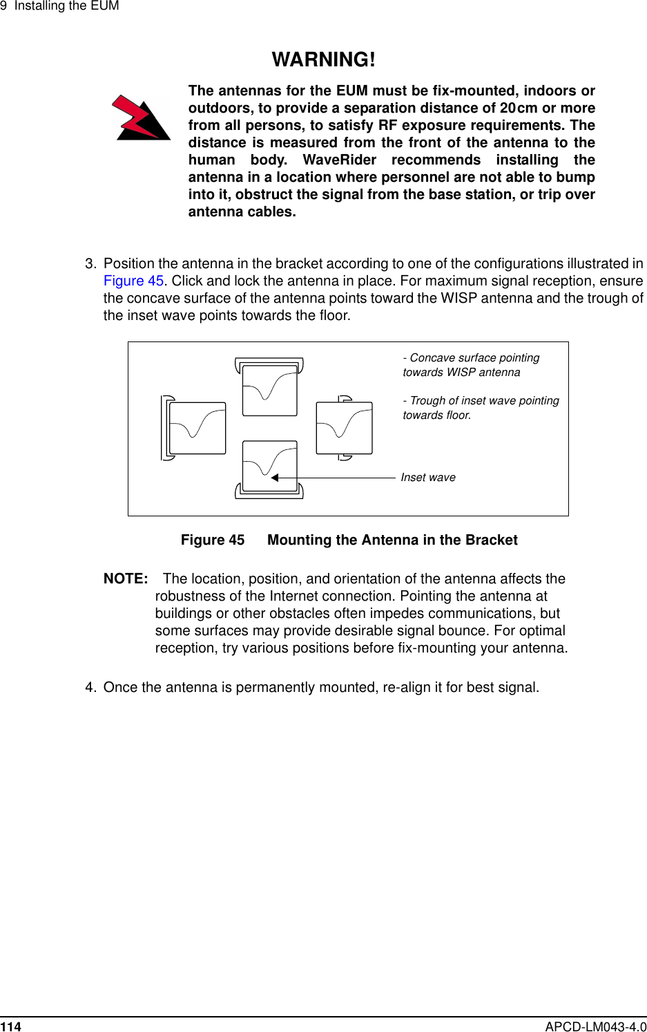
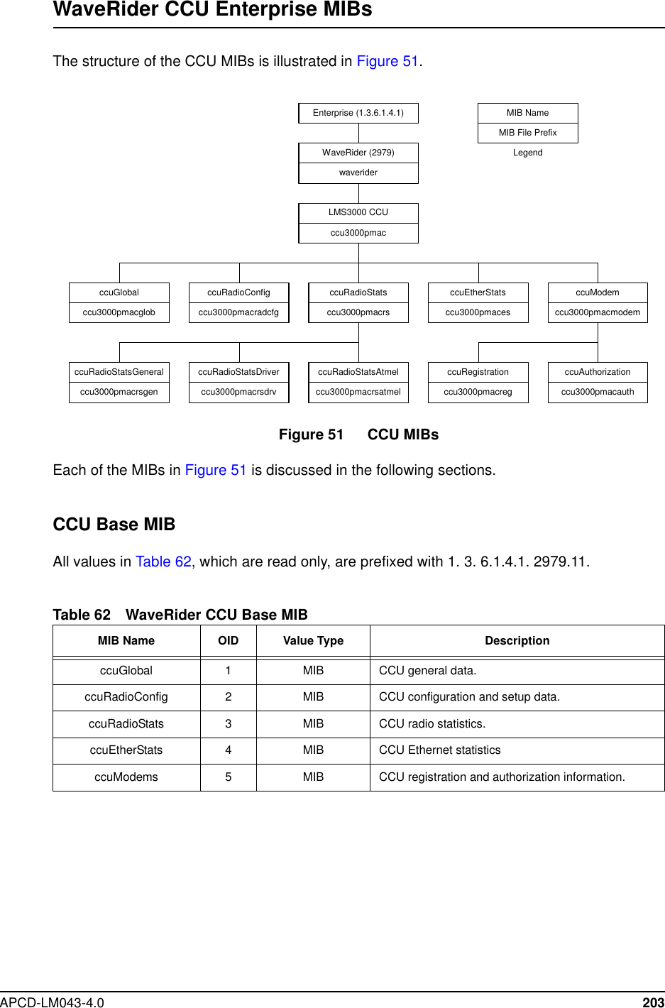
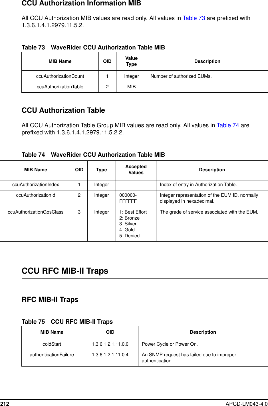
![3 Detailed DescriptionAPCD-LM043-4.0 41Table 8 Factory Default GOS Configuration FileNOTE: While recognizing that the performance of data transmissionthrough packet radio networks is randomly dependent on manyvariables, typical FTP rates based on empirical data are includedin the table to demonstrate the performance that the operatormight expect on single, large FTP transfers using maximum-sizedpackets.There are several important observations that can be made about the above service-classdescriptions:• All of the default service classes impose a limit on the maximum polling rate.• The Silver and Gold service classes have a lower bound on the polling rate (12 and 22polls per second [pps] respectively). The Polling MAC treats this limit as a minimumcommitted level, which is subject to overall radio link capacity.• In determining the order and frequency with which to poll EUMs, the CCU first tries toensure all associated EUMsarepollednomorefrequentlythanthemaximumserviceclass polling rate, and no less frequently than the minimum service class polling rate.• As the system usage increases, the end-user throughput in all classes decreasesfrom the maximum. Bronze users see the largest reduction, then Gold users, and thenBest Effort users. When all users have been reduced to 256 kbps (the minimumthreshold for Gold), the next reduction will be shared by the Best Effort, Bronze, andSilver class users (Gold will not be reduced further), until the minimum threshold forSilver is reached. After this, if further reductions are required, this reduction would beshared equally between the Best Effort and Bronze users.In practice, the bursty nature of Internet usage is such that this methodical reduction inthroughput is not apparent to the end-user, and these variations in service level tendto be instantaneous and transitory. Overall, end-users tend to see a relatively highaverage throughput consistent with their assigned GOS class, as is shown later indetailed simulation results based on real user data.ServiceClass Polling Rate (polls/second) FTP Rate(see note) OperatorAssignedBestEffort 1-34 0-384kbps YesBronze 1 - 90 0 - 1024 kbps YesSilver 12 - 22 128 - 256 kbps YesGold 22 - 46 256 - 512 kbps YesBroadcast Varies with channel load,from 16 to 935 Not applicable NoDenied 0 0 Yes](https://usermanual.wiki/Vecima-Networks/EUM3003.Users-Manual/User-Guide-299333-Page-59.png)

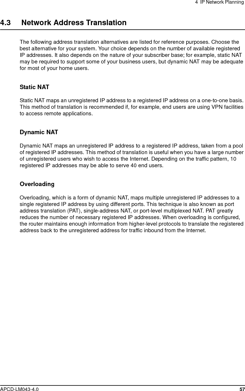
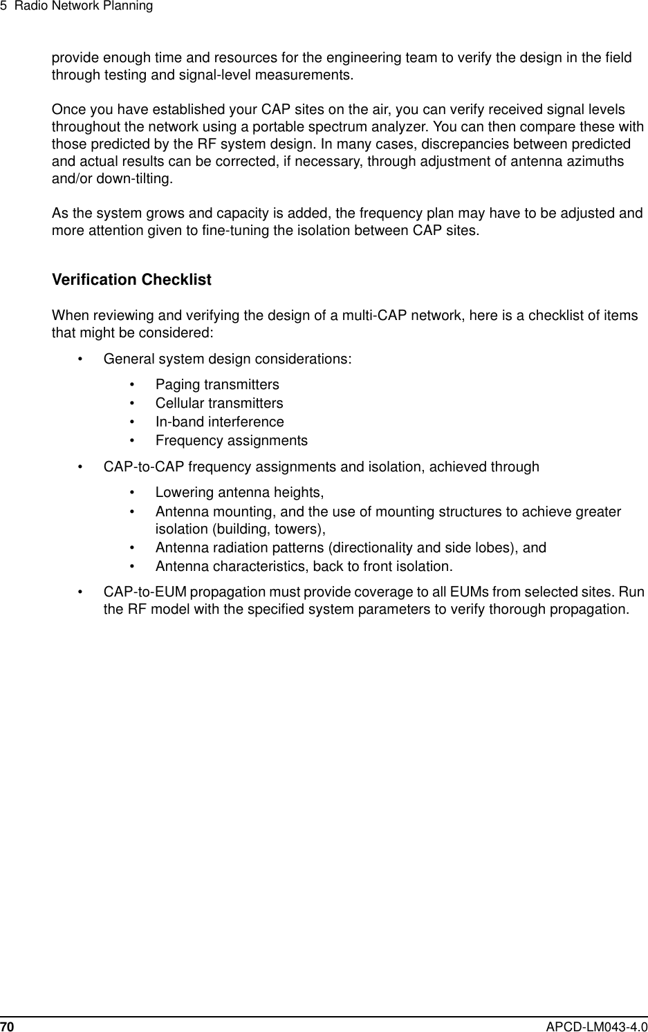
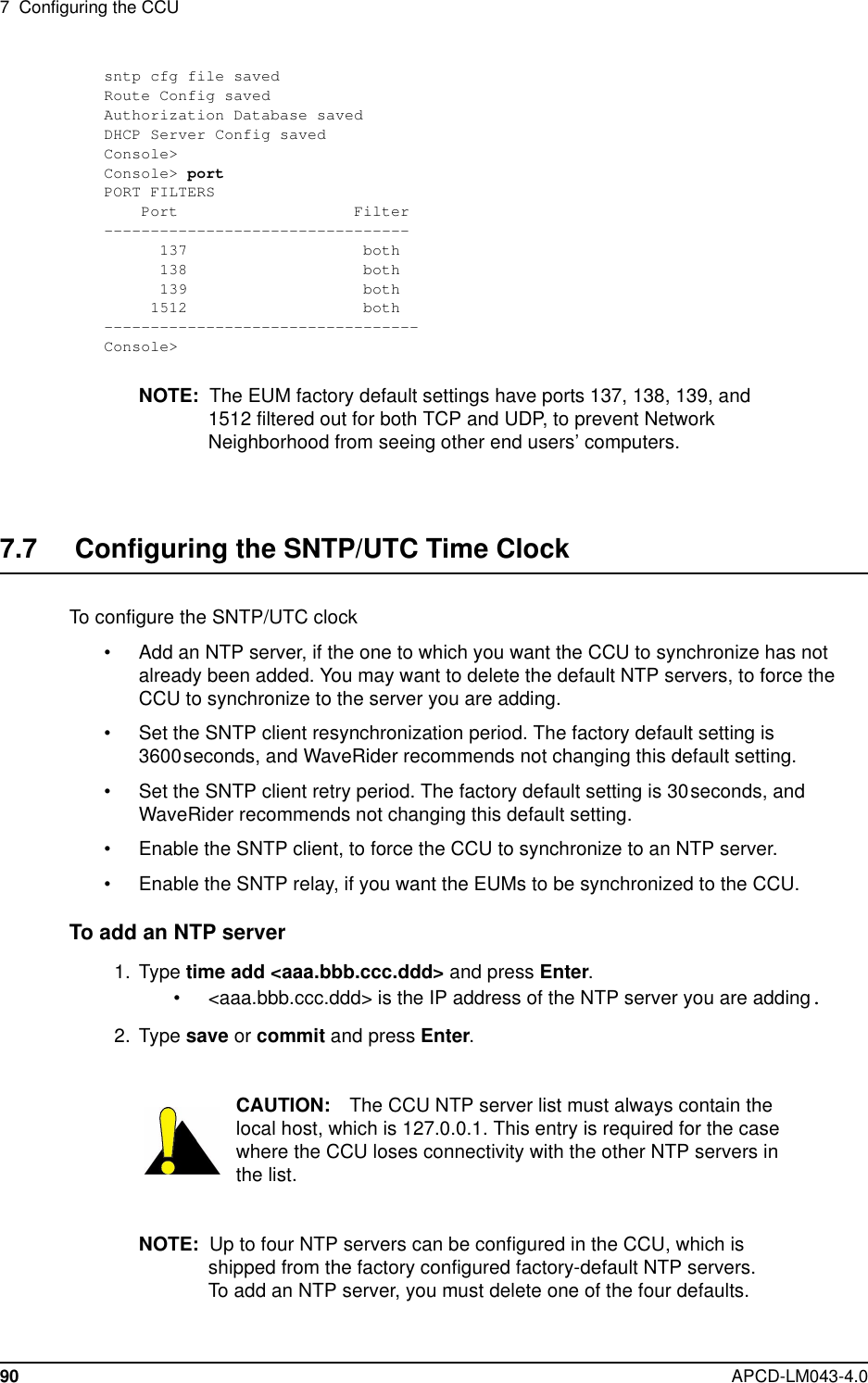

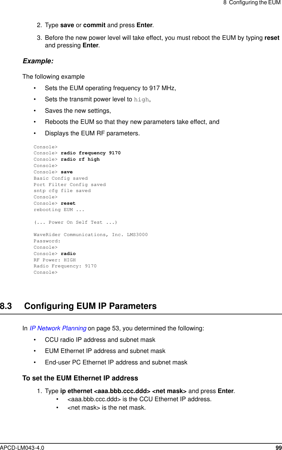
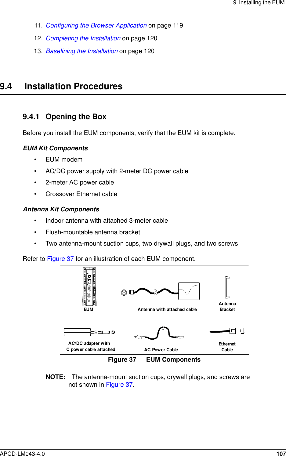
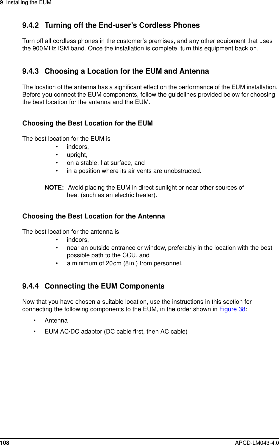
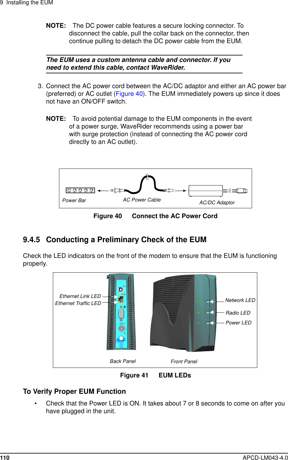
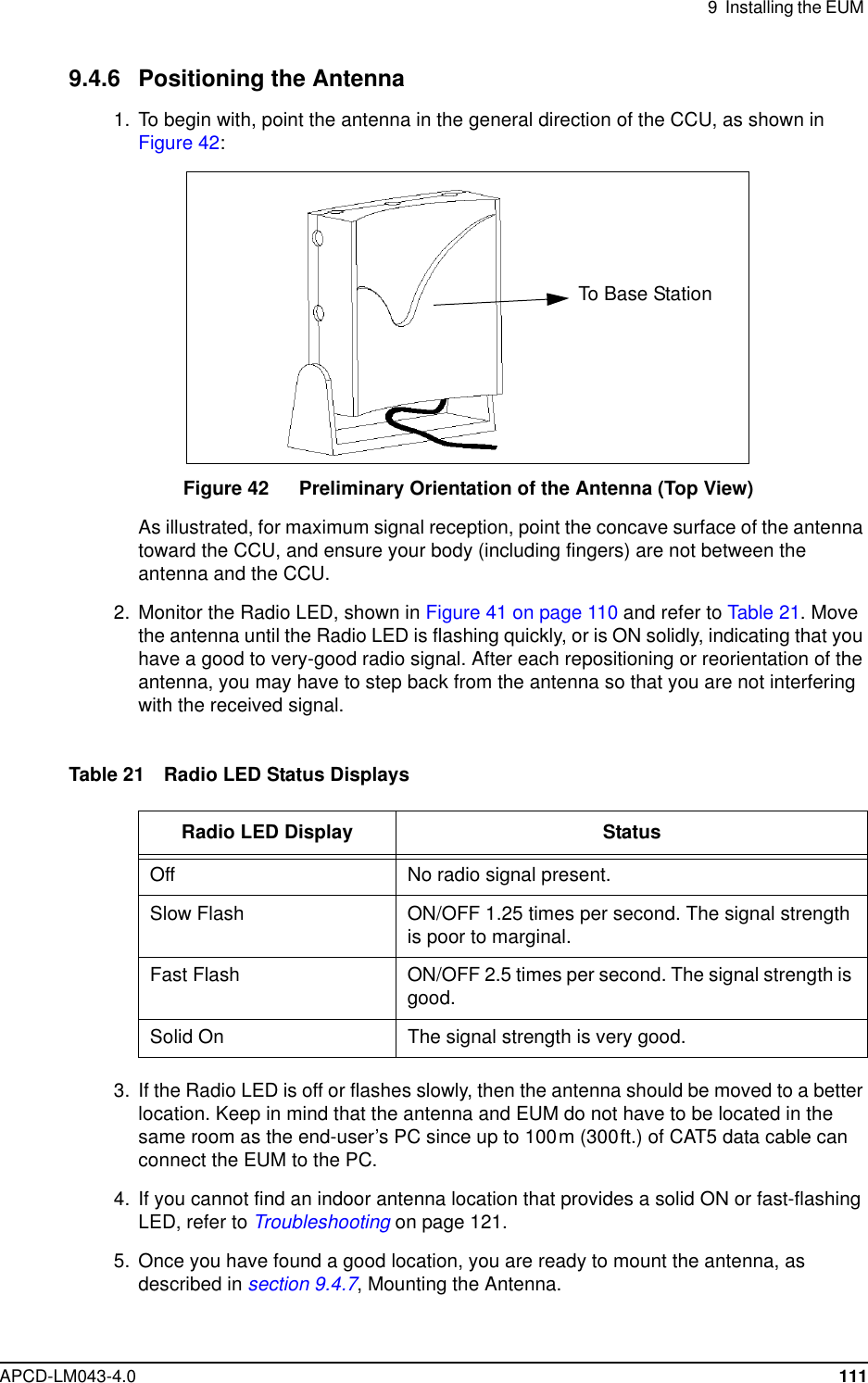
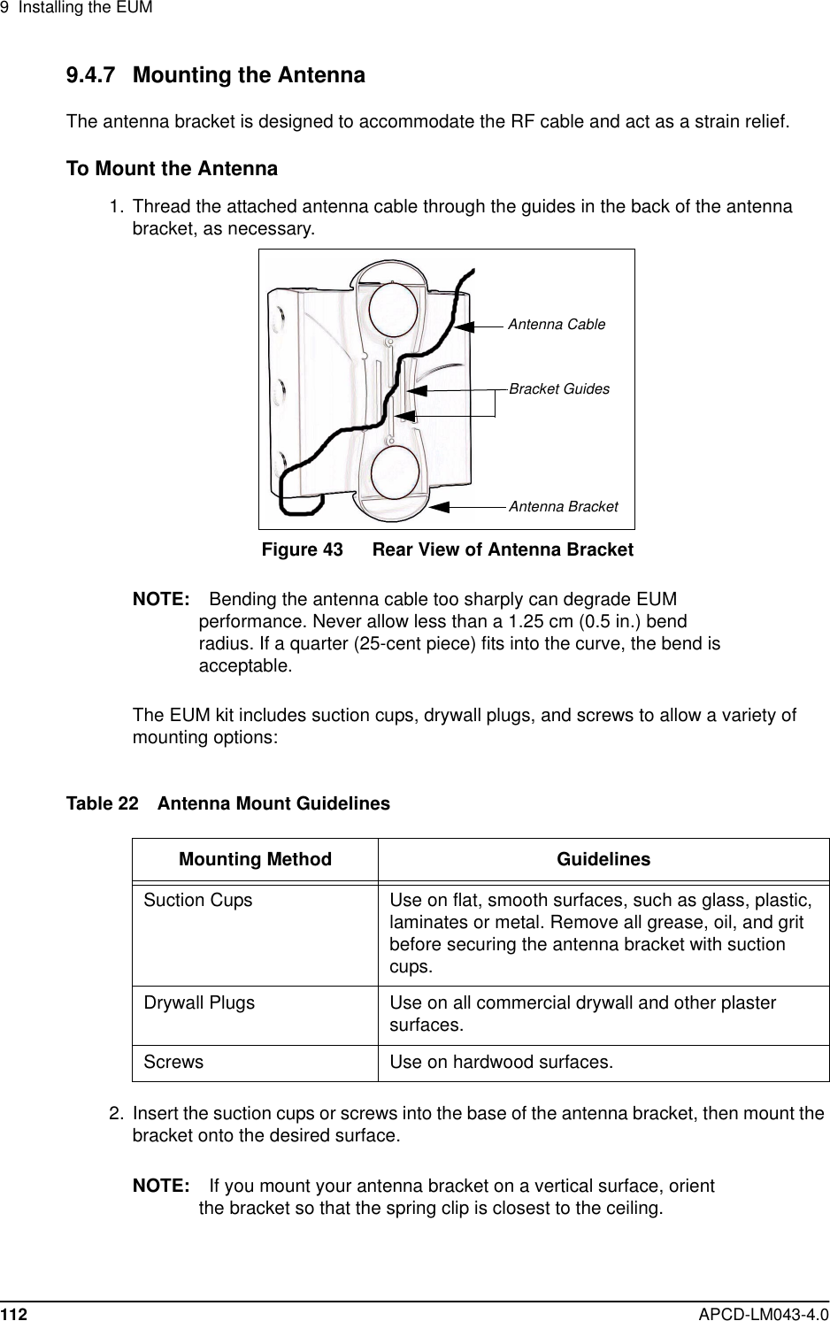
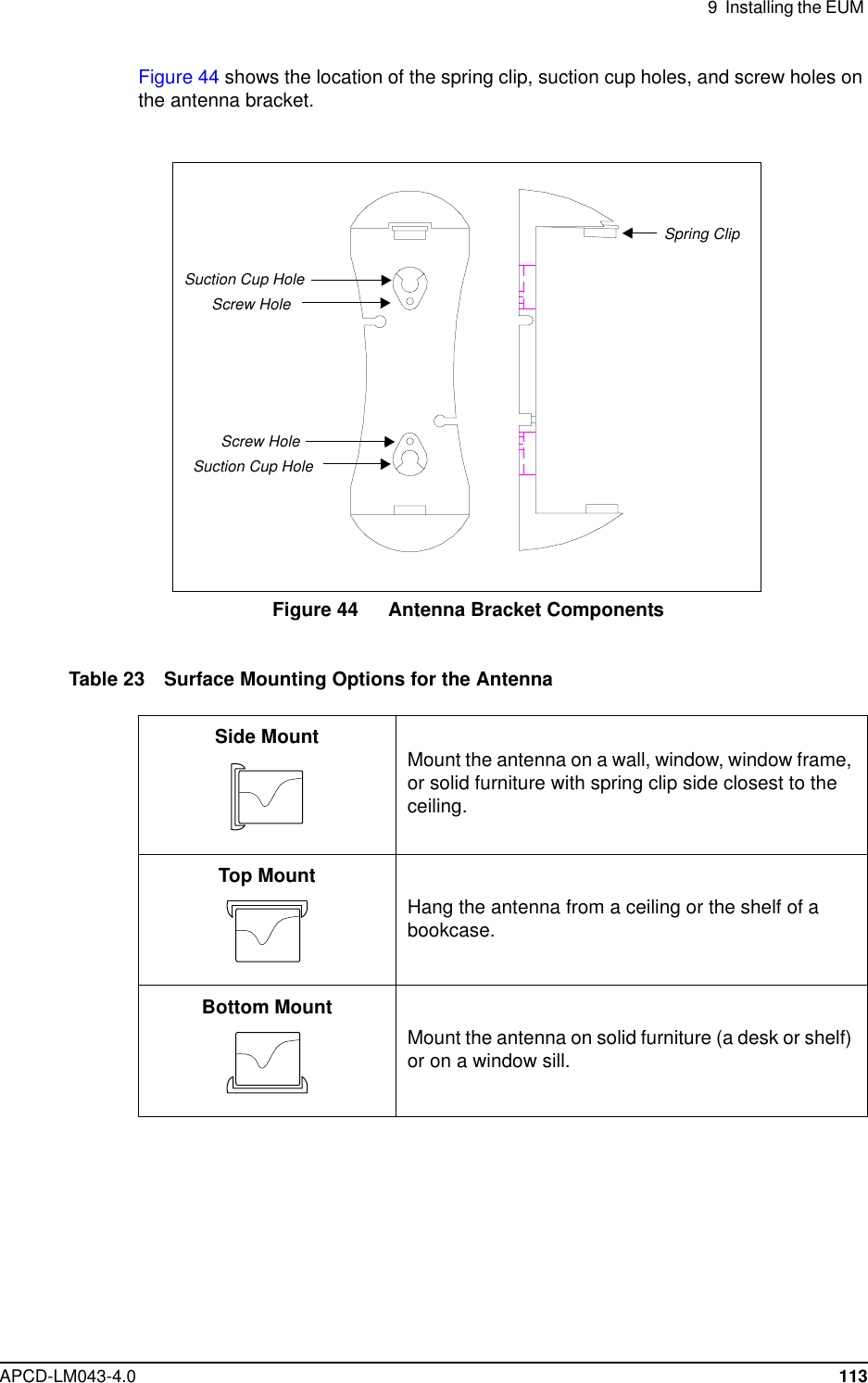
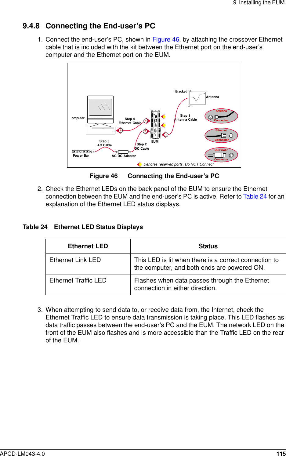
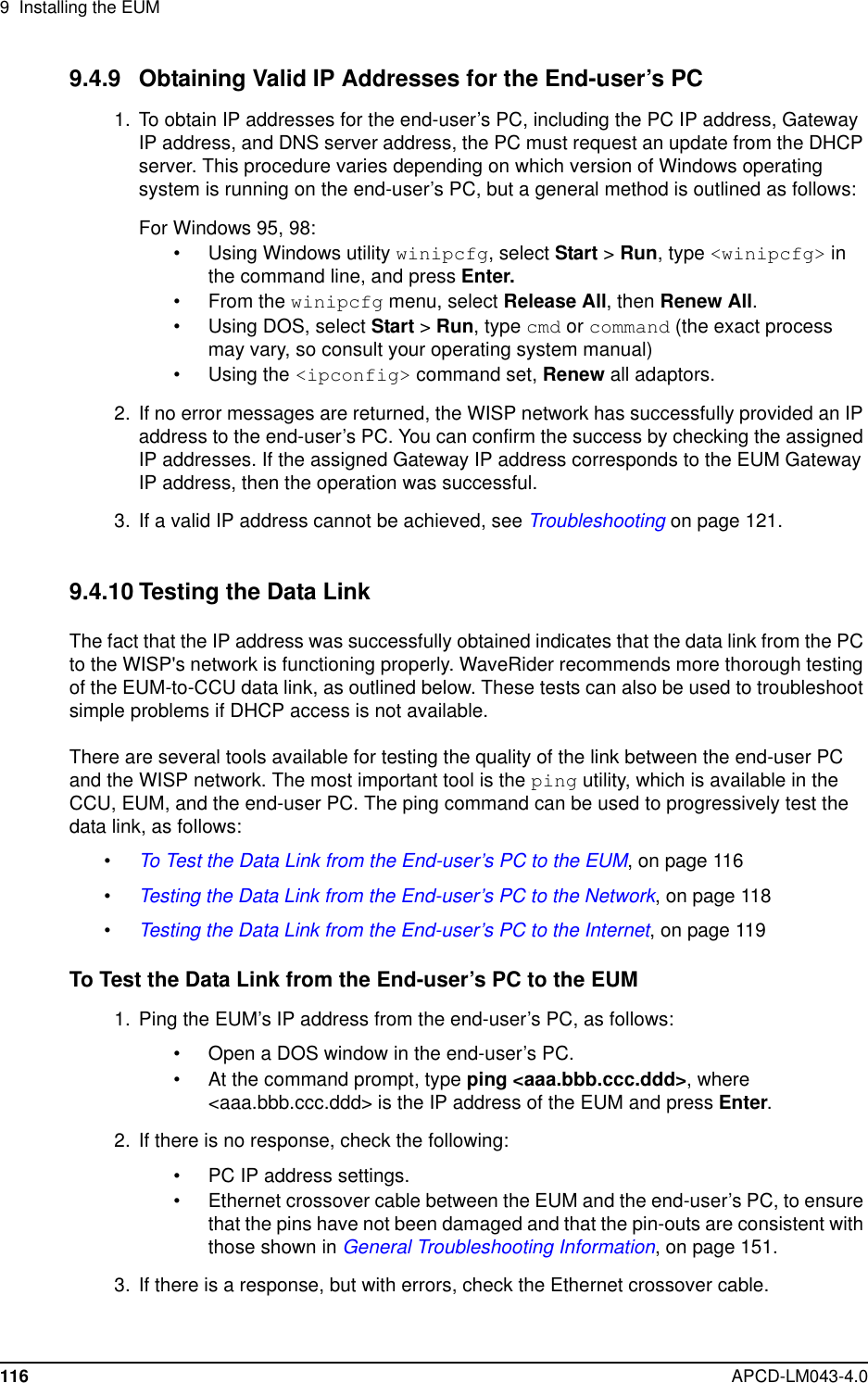
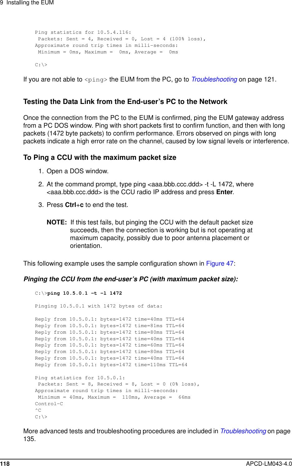
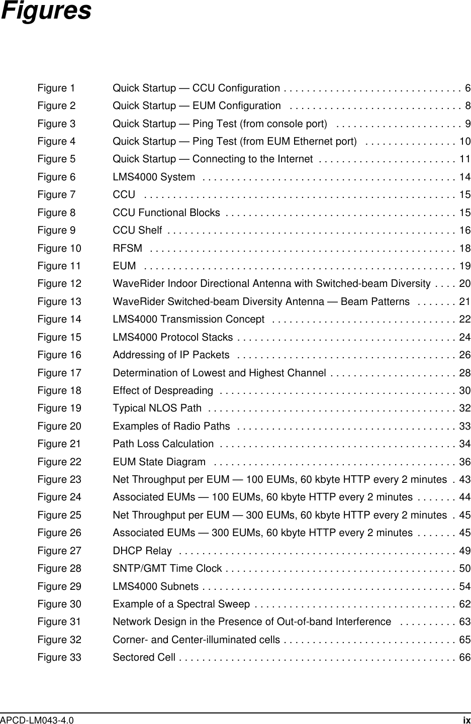
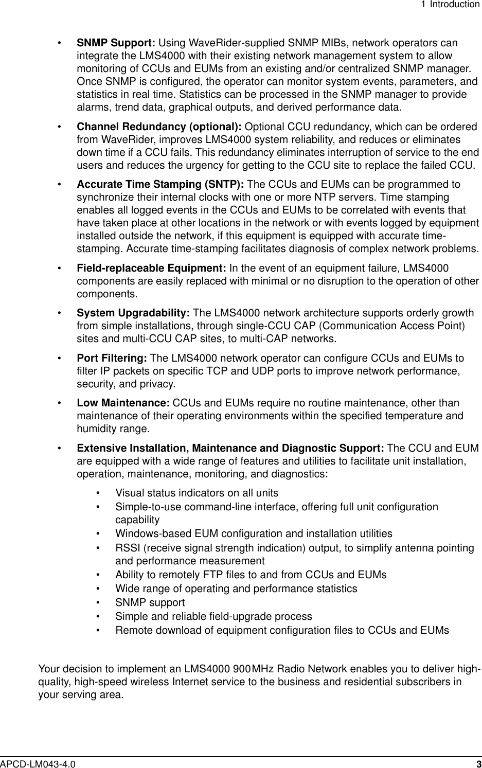
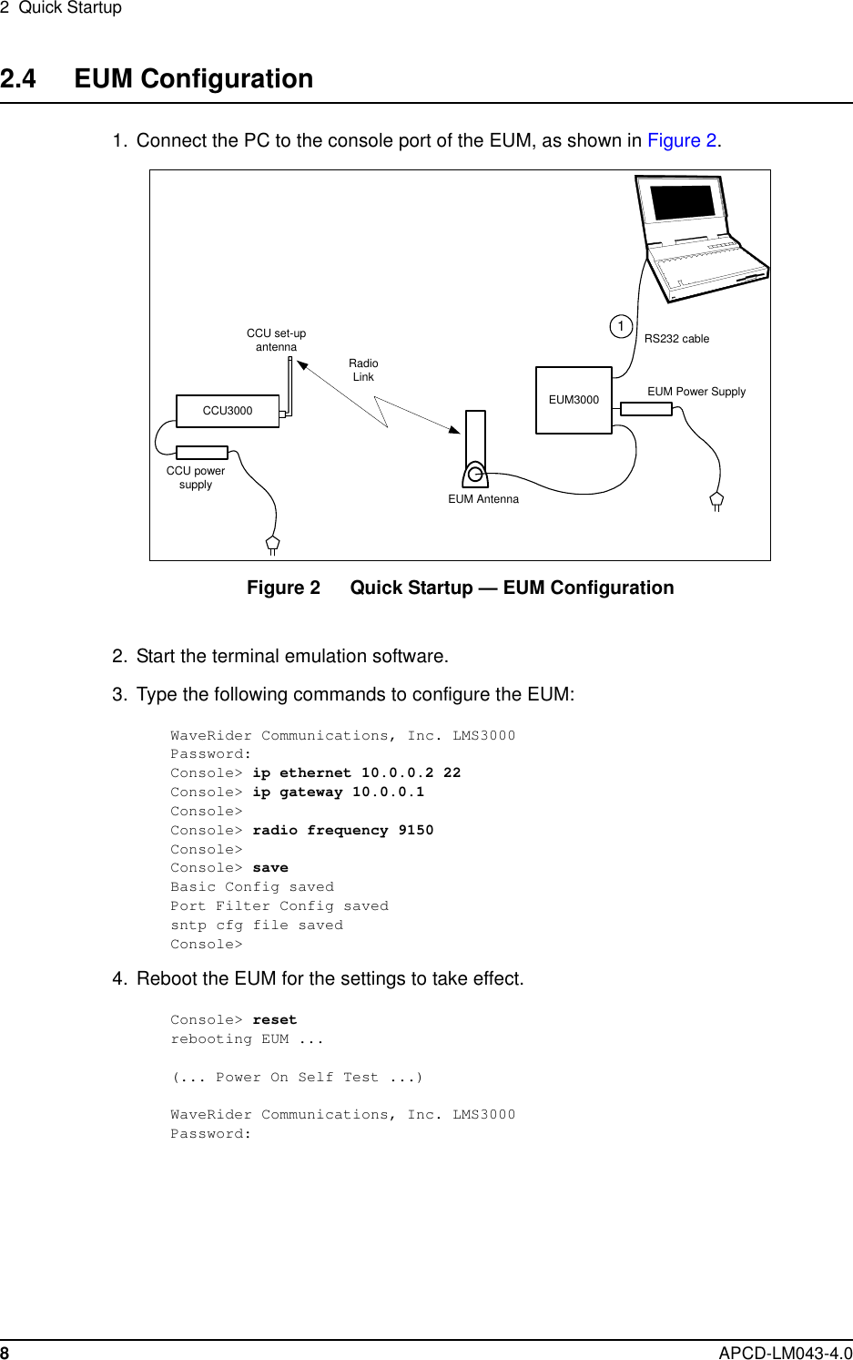
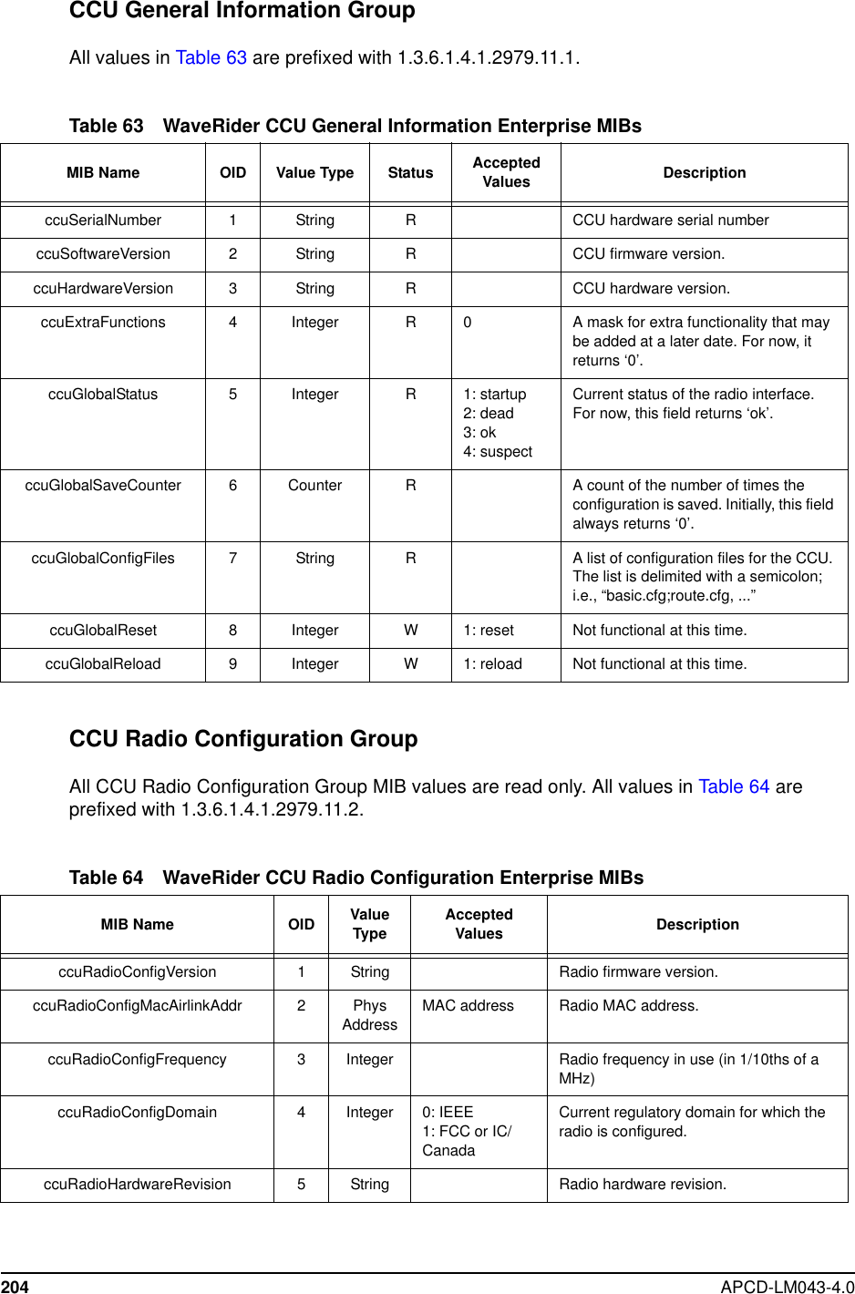
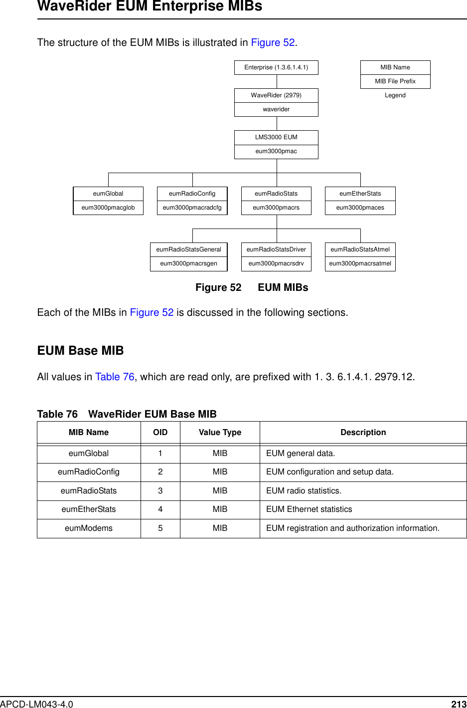
![9 Installing the EUMAPCD-LM043-4.0 119Testing the Data Link from the End-user’s PC to the InternetUse the following test to determine whether the end-user’s PC can communicate with theInternet.Pinging an Internet site from the PC using the site’s IP address:C:\>ping 207.23.175.75Pinging 207.23.175.75 with 32 bytes of data:Reply from 207.23.175.75: bytes=32 time=90ms TTL=113Reply from 207.23.175.75: bytes=32 time=80ms TTL=113Reply from 207.23.175.75: bytes=32 time=80ms TTL=113Reply from 207.23.175.75: bytes=32 time=70ms TTL=113Ping statistics for 207.23.175.75:Packets: Sent = 4, Received = 4, Lost = 0 (0% loss),Approximate round trip times in milli-seconds:Minimum = 70ms, Maximum = 90ms, Average = 80msC:\>Use the following test to verify that the DNS server IP address is correctly configured in theend-user’s PC and is operating properly:Pinging an Internet site from the PC, using the site’s domain name:C:\>ping www.waverider.comPinging waverider.com [207.23.175.75] with 32 bytes of data:Reply from 207.23.175.75: bytes=32 time=70ms TTL=113Reply from 207.23.175.75: bytes=32 time=90ms TTL=113Reply from 207.23.175.75: bytes=32 time=60ms TTL=113Reply from 207.23.175.75: bytes=32 time=50ms TTL=113Ping statistics for 207.23.175.75:Packets: Sent = 4, Received = 4, Lost = 0 (0% loss),Approximate round trip times in milli-seconds:Minimum = 50ms, Maximum = 90ms, Average = 67msC:\>9.4.11 Configuring the Browser ApplicationFollow the manufacturer's instructions for configuring the end-user’s browser, so that itcorrectly uses the PC Ethernet interface. Once you have done this:1. Launch the browser2. Confirm access to sites of interest.3. Monitor the access speed using a test site, such as http://speed-test.net](https://usermanual.wiki/Vecima-Networks/EUM3003.Users-Manual/User-Guide-299333-Page-137.png)
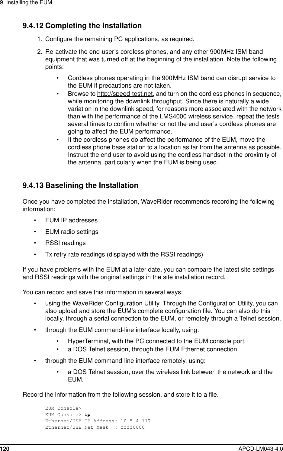

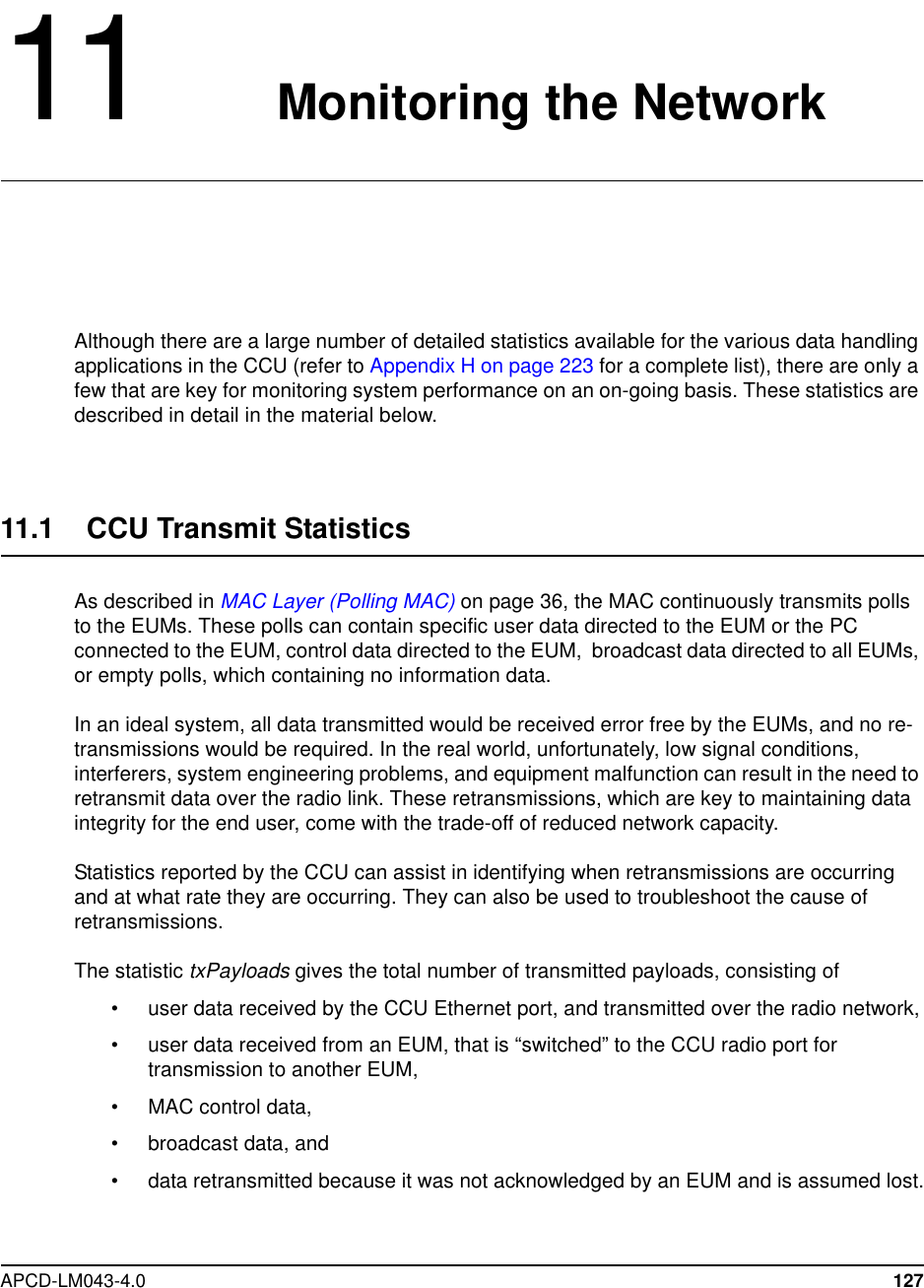
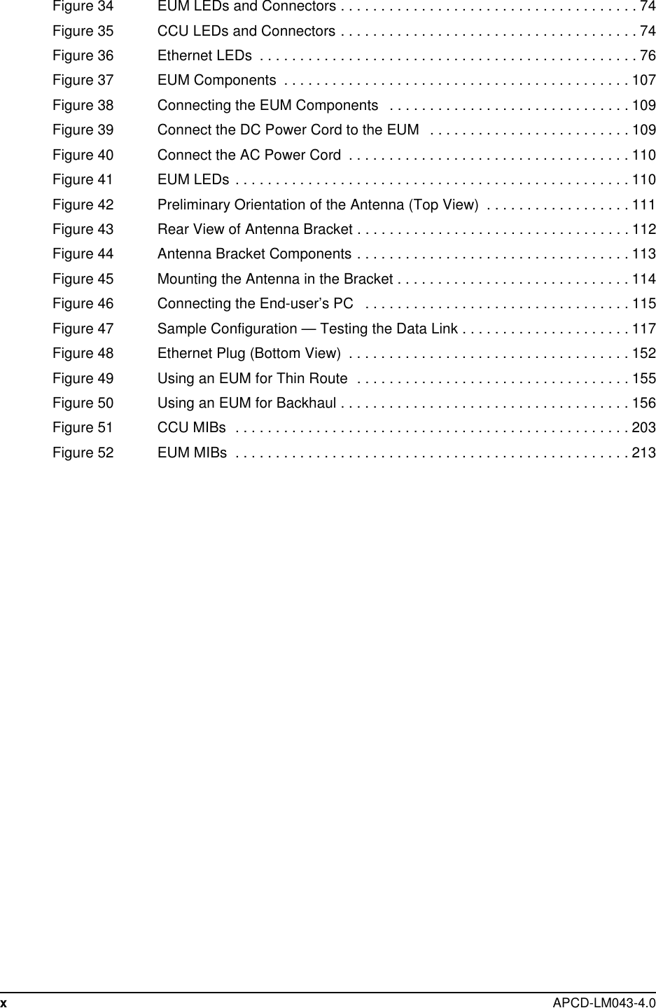
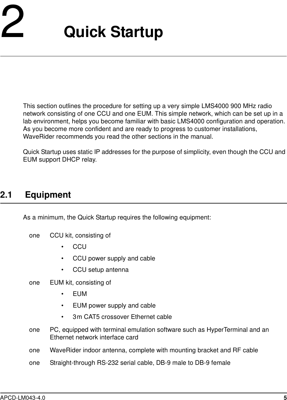
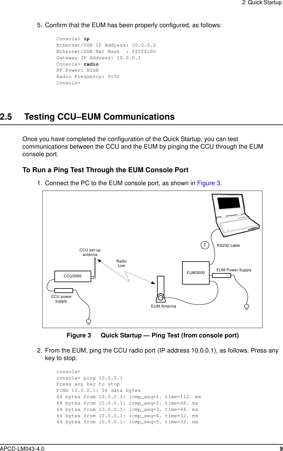
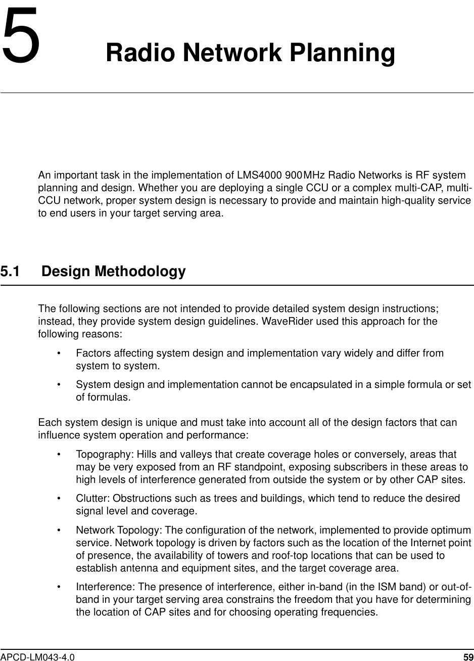
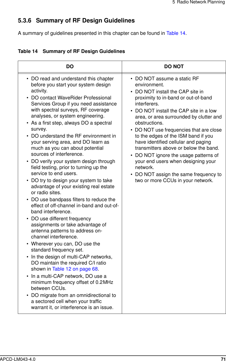
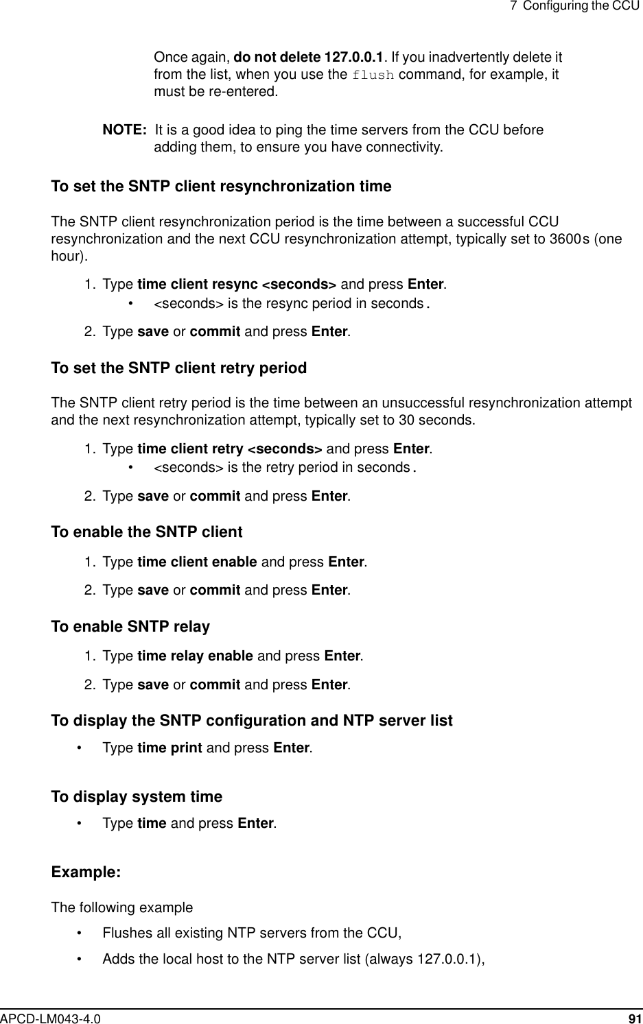
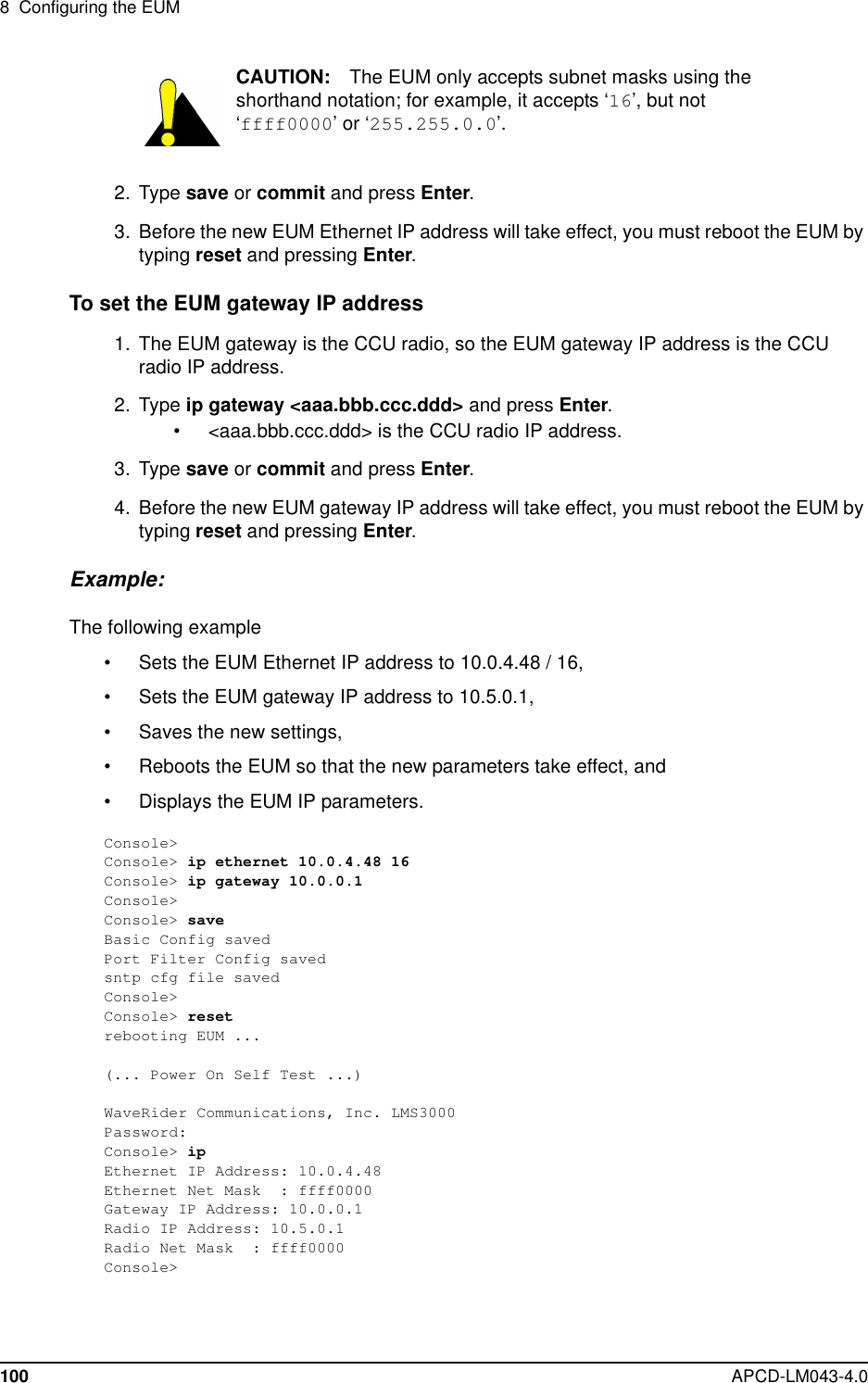
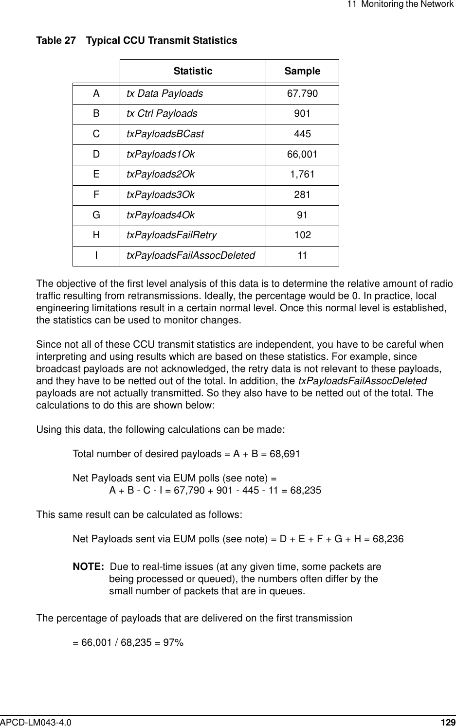
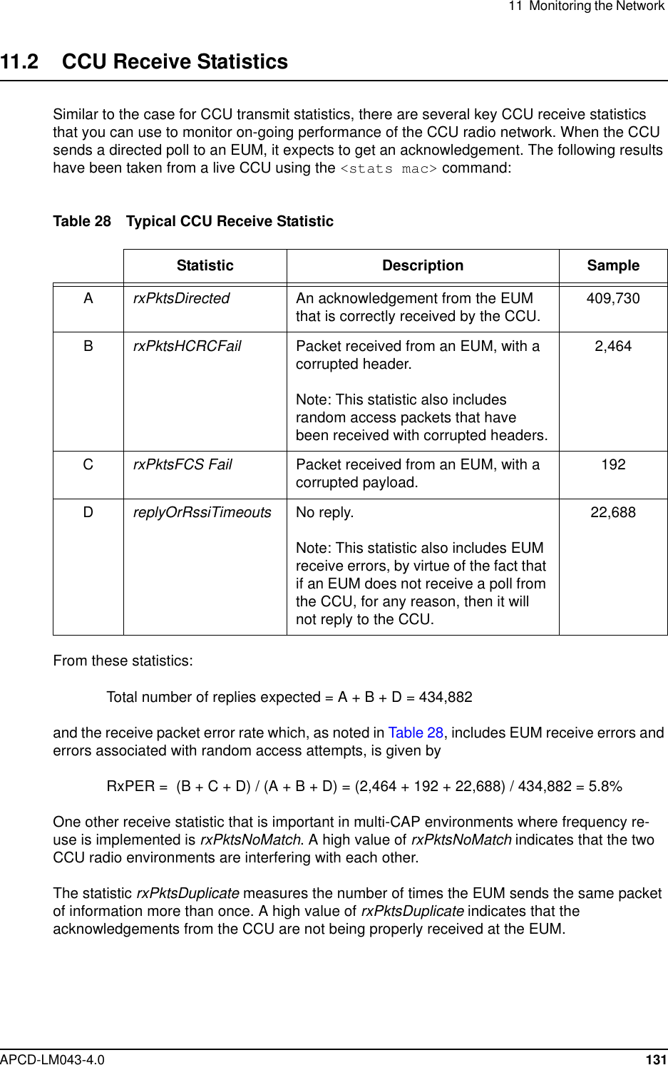
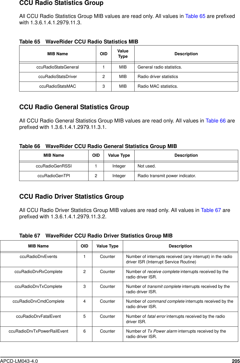
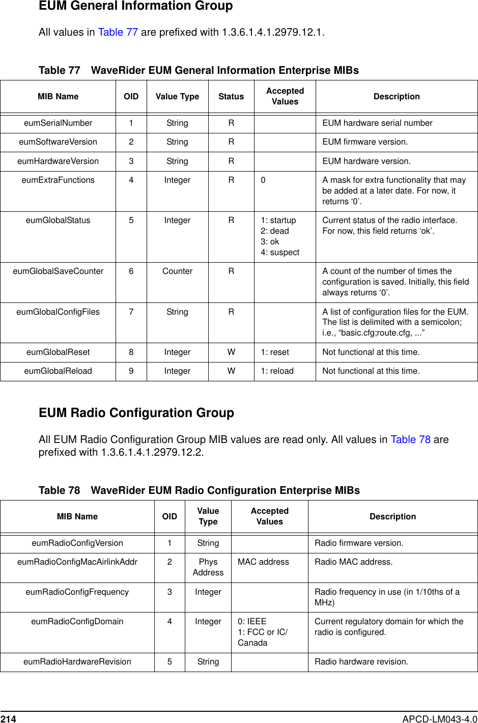
![11 Monitoring the Network128 APCD-LM043-4.0Examining this statistic in more detail, txPayloads includes• Tx Data Payloads which, in turn, includes• data coming from the Ethernet port of the CCU (either end-user data oroperator monitoring [SNMP] data),• data coming from EUM-originated data payloads that have been “switched” tothe CCU radio port (for transmission to other EUMs), and• broadcast data to all EUMs(TxPayloadsBCast).NOTE: The Tx Data Payloads described above are both transmittedduring specific EUM poll periods.• Tx Ctrl Payloads — Control data generated in the CCU, and used to configure, orrequest status from, the EUMs. Tx Ctrl Payloads are transmitted during specific EUMpoll periods.• Retransmitted data — Data that is not acknowledged after a transmission and isassumed to be lost or corrupted.Understanding the relationship between these values helps you monitor the integrity of a CCUradio environment.All non-broadcast payloads (hence, “directed” payloads) are explicitly acknowledged by theEUMs. For these payloads, the result of a transmission during an EUM poll cycle will be one ofthe following:Table 26 Possible Transmission OutcomesTo put these values in perspective, the following samples have been taken from a live CCU,using the <stats mac> CLI command:Result of Transmission Reported StatisticPayload is delivered to an EUM andacknowledged on the first poll. txPayloads1OkPayload is transmitted twice, after which anacknowledgement is received. txPayloads2OkPayload is transmitted three times, afterwhich an acknowledgement is received. txPayloads3OkPayload is transmitted four times, afterwhich an acknowledgement is received. rxPayloads4OkNo acknowledgement received after fourtransmissions, and the payload isdiscarded.txPayloadsFailRetryPayload is not transmitted at all. txPayloadsFailAssocDeleted](https://usermanual.wiki/Vecima-Networks/EUM3003.Users-Manual/User-Guide-299333-Page-146.png)


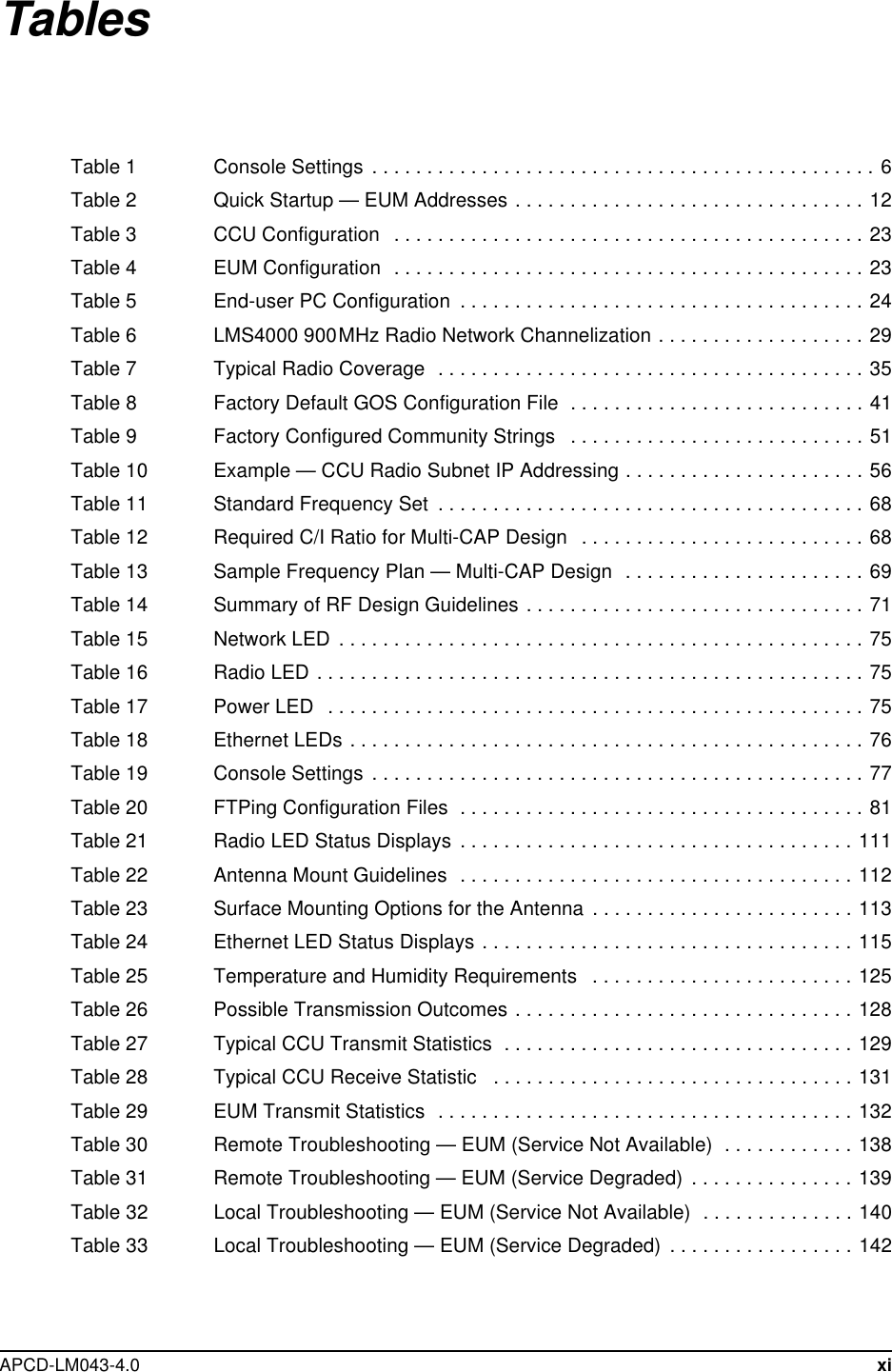
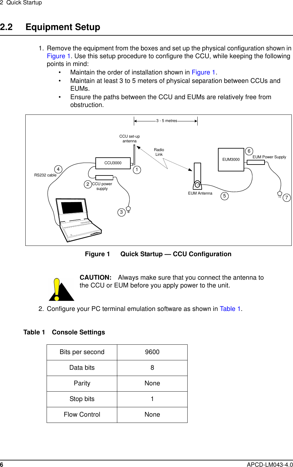
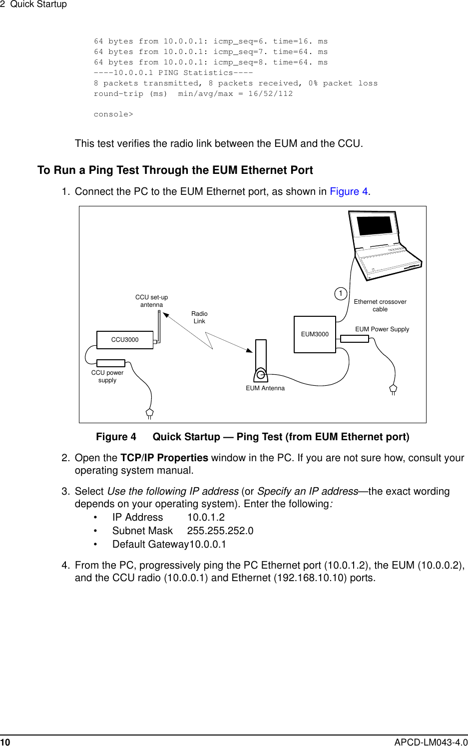
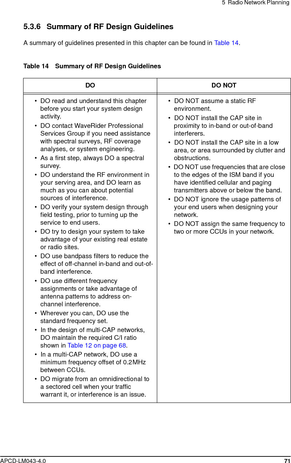
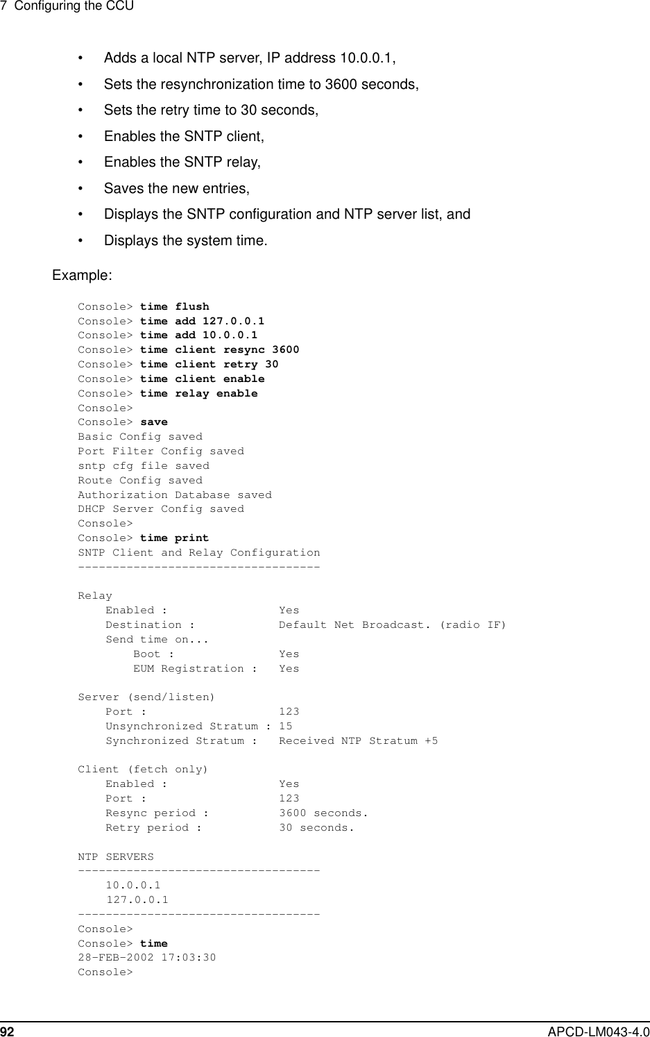
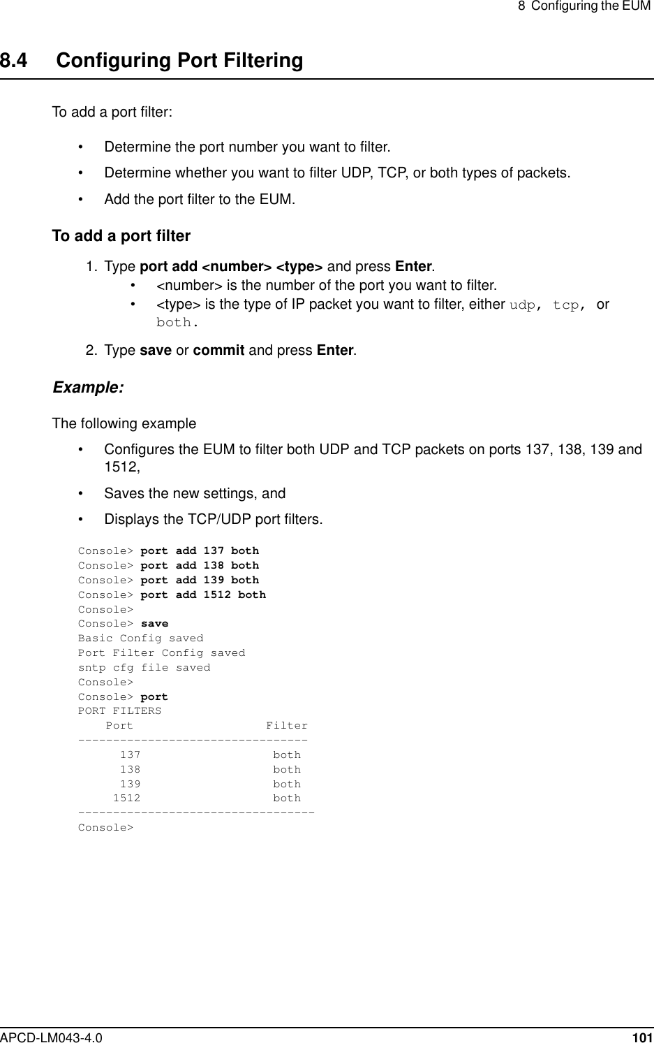
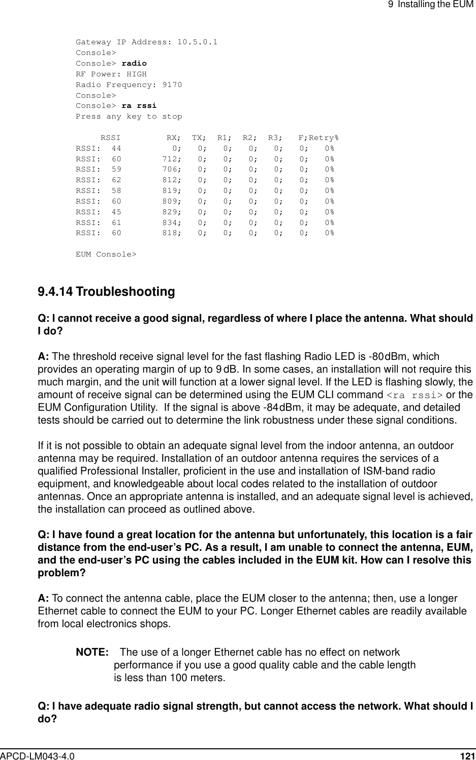
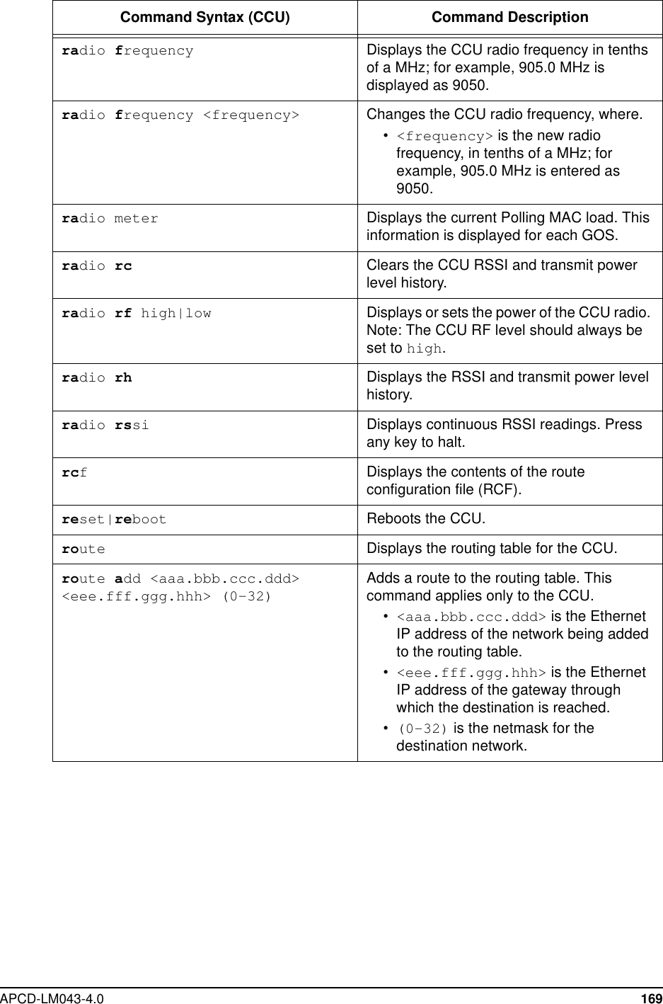
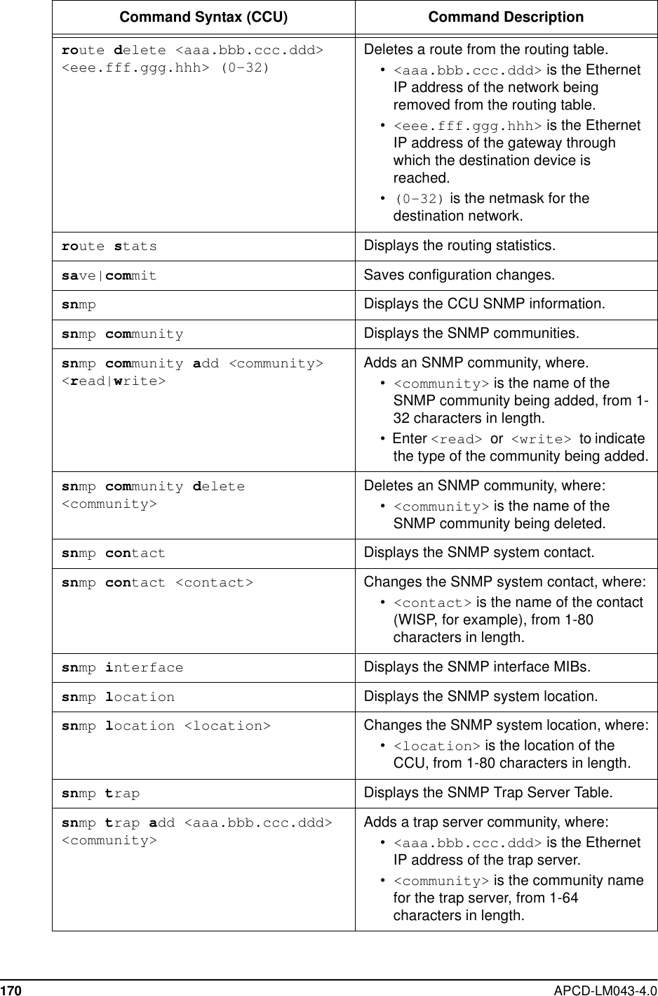
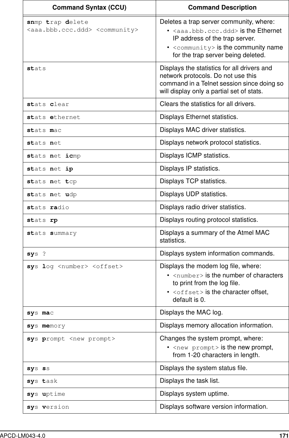
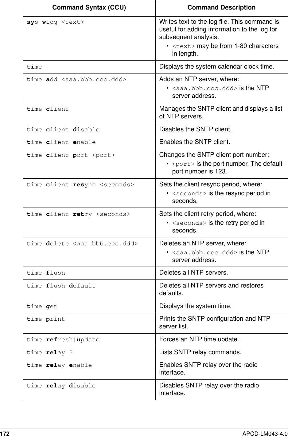
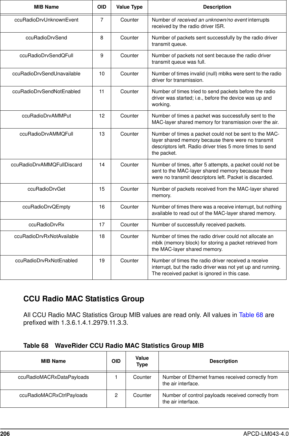
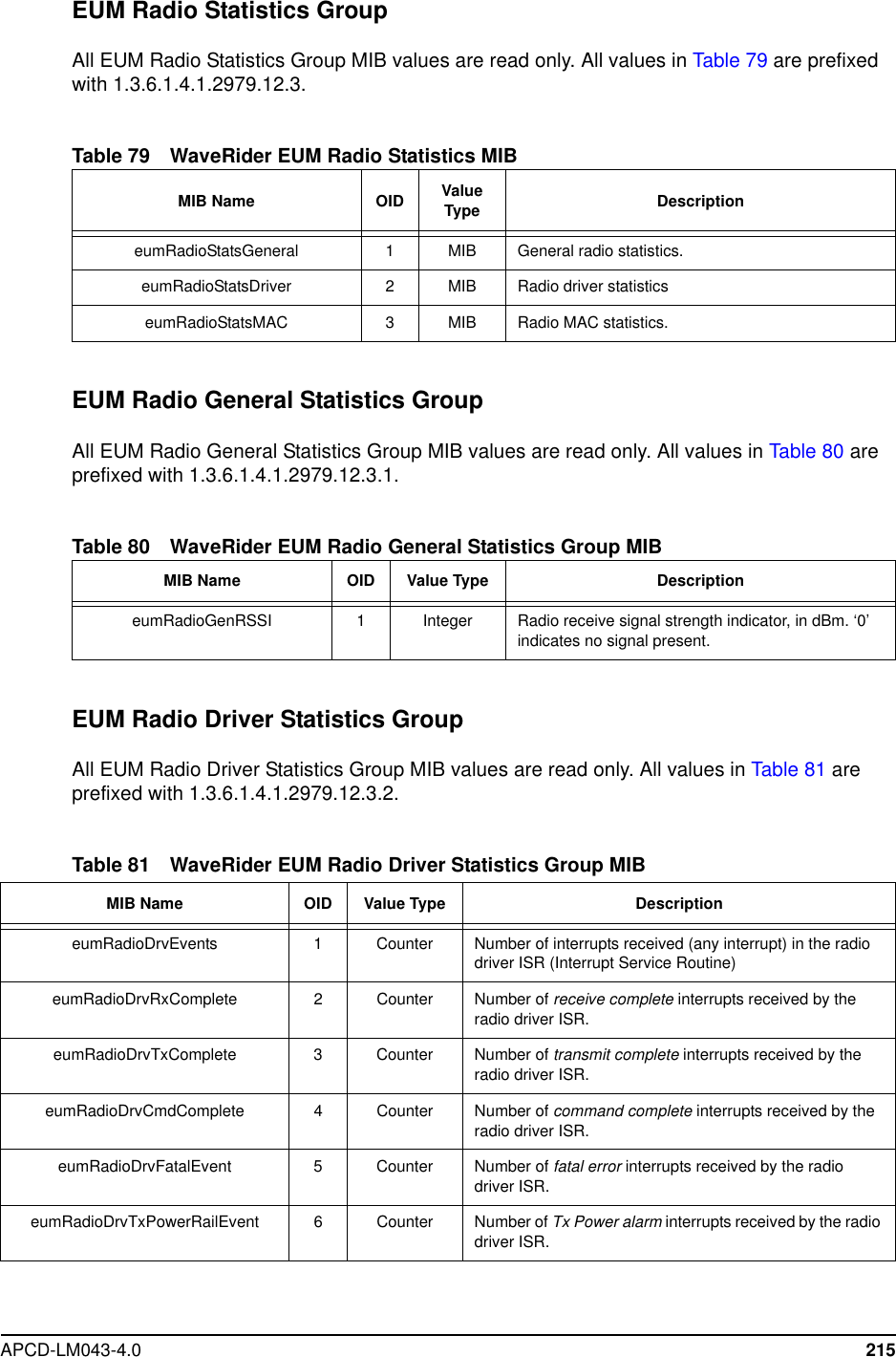
![APCD-LM043-4.0 165CCU Command-line SyntaxTable 46 CCU Command-Line SyntaxCommand Syntax (CCU) Command DescriptionaddDisplays the Address Table.addflush Removes all entries from the AddressTable.addrem <eum id> Removes an EUM ID from the AddressTable, where:•<eum id> is the EUM ID, formatted inhexadecimal as XX:XX:XX.airDisplays the Registration Table.airassociations Displays the maximum association count.airdelete <eum id> Deletes an EUM from the RegistrationTable, where:•<eum id> is the EUM ID, formatted inhexadecimal XX:XX:XX.airdereg Displays the deregistration count.airdereg <value> Changes the deregistration count, where:•<value> is the deregistration count,from 1 to 254.airfdereg <eum id> Forces deregistration of an EUM, where:•<eum id> is the EUM ID, formatted inhexadecimal as XX:XX:XX.airflush Flushes the Registration Table.arpDisplays the ARP Table.arpadd <aaa.bbb.ccc.ddd><XX.XX.XX.XX.XX.XX> [flags]Adds an entry to the ARP Table, where.•<aaa.bbb.ccc.ddd> is the IPaddress of the new entry.•<XX:XX:XX:XX:XX:XX> is theEthernet address, in hexadecimalformat.•[flags] is always set to 4, meaningthe entry is permanent and doesn’t timeout, as long as the CCU or EUM is ON.arpdel <aaa.bbb.ccc.ddd> Deletes an entry from the ARP Table:•<aaa.bbb.ccc.ddd> is the IPaddress of the entry being deleted.arpflush Clears the ARP Table.](https://usermanual.wiki/Vecima-Networks/EUM3003.Users-Manual/User-Guide-299333-Page-183.png)
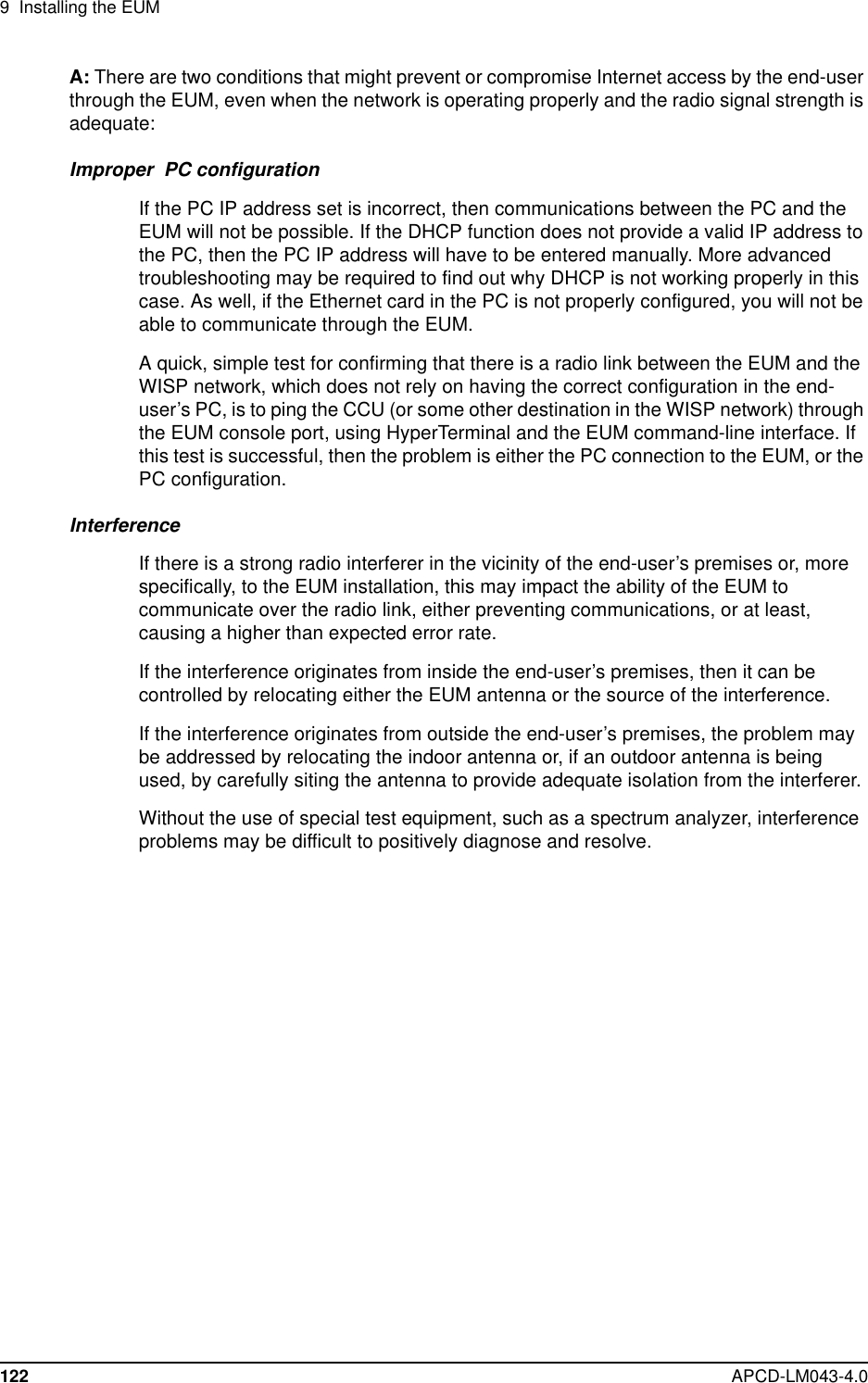
![APCD-LM043-4.0 173time relay ip|destination<aaa.bbb.ccc.ddd>|broadcastSends NTP messages to a single EUM,where:•<aaa.bbb.ccc.ddd> is the IPaddress of the EUM.or sends NTP messages to all EUMs ifbroadcast is entered.time server ? Displays NTP server utilities.time server port <port> Changes the SNTP server port, where:•<port> is the port number.time server stratum <value> Sets NTP stratum or relative stratum offset,where:•<value> is the NTP offset, from 1-5when sync, and 6-15 when unsync.time set <time>. Sets the system time (Greenwich MeanTime), where:•<time> is formatted [dy-mon-yearhh:mm:ss] or [mm-dd-yy hh:mm:ss}.This command overwrites the local timeobtained from the NTP server. The localtime will be updated on the next refresh fromthe NTP server.time stats Displays time statistics.Command Syntax (CCU) Command Description](https://usermanual.wiki/Vecima-Networks/EUM3003.Users-Manual/User-Guide-299333-Page-191.png)
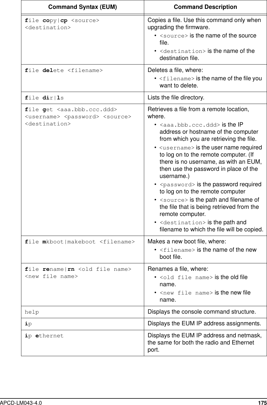
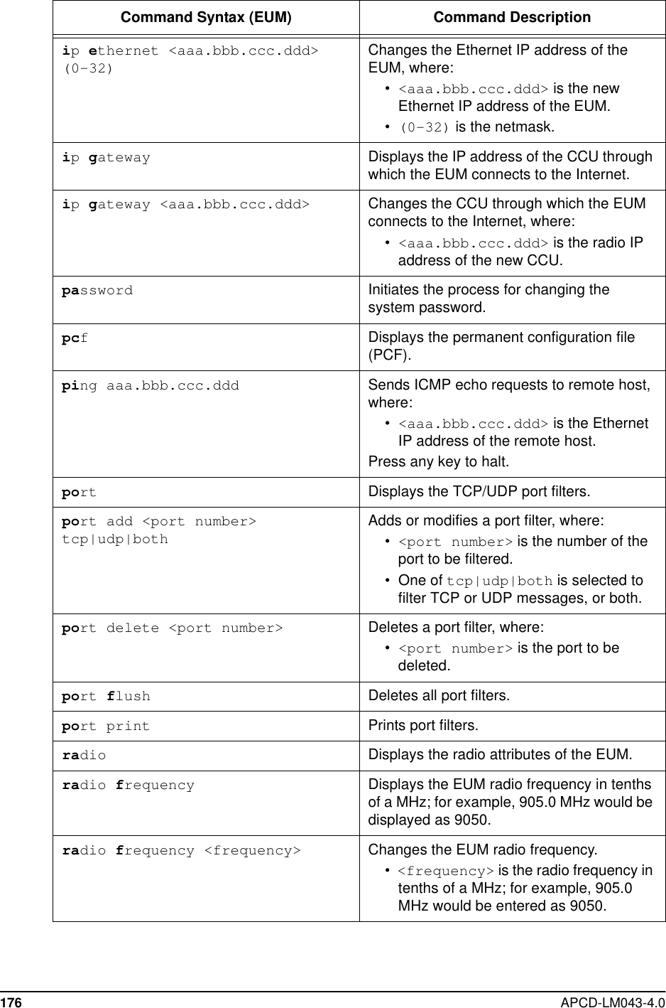
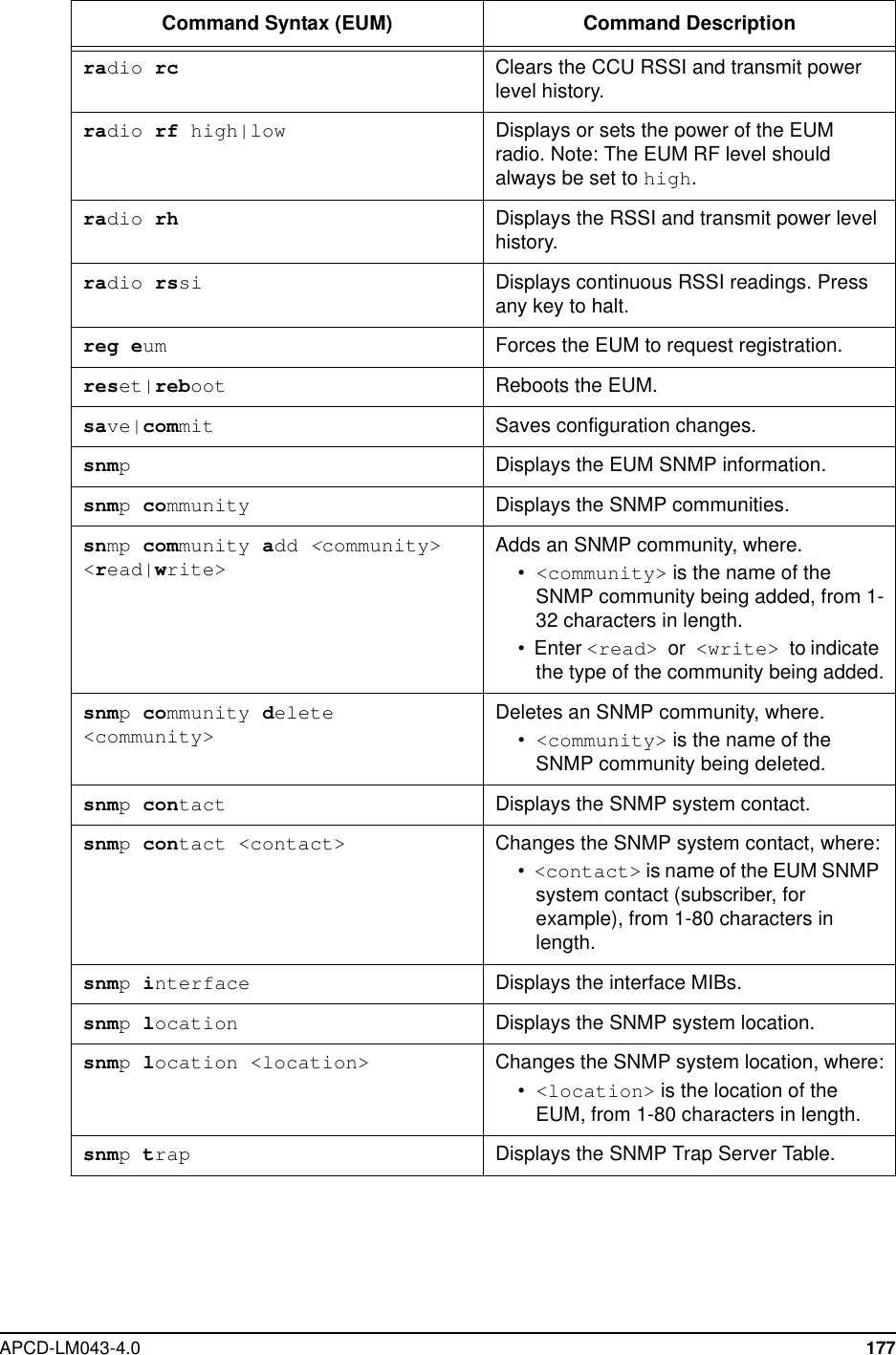
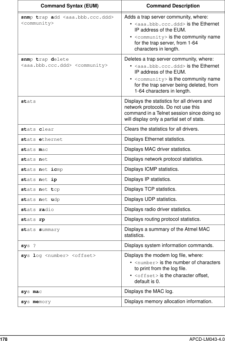
![174 APCD-LM043-4.0EUM Command-line SyntaxTable 47 EUM Command-Line SyntaxCommand Syntax (EUM) Command DescriptionarpDisplays the ARP Table.arpadd <aaa.bbb.ccc.ddd><XX:XX:XX:XX:XX:XX> [flags]Adds an entry to the ARP table, where.•<aaa.bbb.ccc.ddd> is the IPaddress.•<XX:XX:XX:XX:XX:XX> is theEthernet address, in hexadecimalformat.•[flags] is always set to 4, meaningthe entry is permanent and doesn’t timeout, as long as the CCU or EUM is ON.arpdel <aaa.bbb.ccc.ddd> Deletes an entry from the ARP table, where.•<aaa.bbb.ccc.ddd> is the IPaddress of the entry.arpflush Clears the ARP table.arpmap Displays the ARP Map Table.arpmap <aaa.bbb.ccc.ddd> Maps MAC address to IP address<aaa.bbb.ccc.ddd>. The MAC addressis obtained from the ARP Table, or bysending out an ARP request.bcfDisplays the basic configuration file (BCF).cust Displays the Customer Table.cust flush Removes all entries from the CustomerTable.cust max Displays the maximum number ofcustomers.cust max <value> Sets the maximum number of customers,where:•<value> is the maximum number ofcustomers, from 1-50.exit|quit Exits the current console session andreturns to the password prompt.file ? Lists the file system utilities.](https://usermanual.wiki/Vecima-Networks/EUM3003.Users-Manual/User-Guide-299333-Page-192.png)
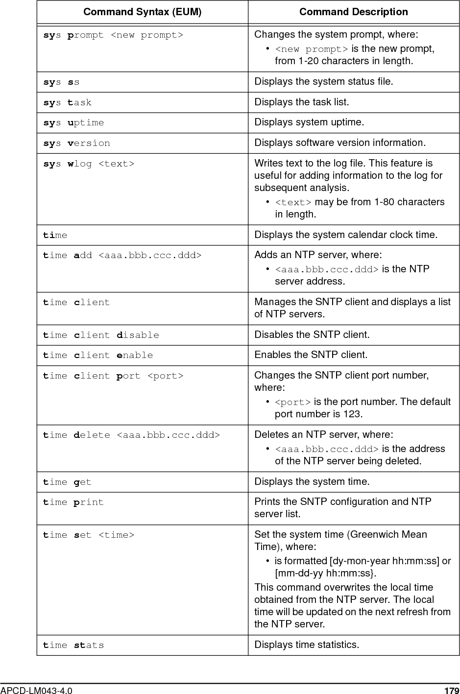
![APCD-LM043-4.0 179sysprompt <new prompt> Changes the system prompt, where:•<new prompt> is the new prompt,from 1-20 characters in length.sysssDisplays the system status file.systask Displays the task list.sysuptime Displays system uptime.sysversion Displays software version information.syswlog <text> Writes text to the log file. This feature isuseful for adding information to the log forsubsequent analysis.•<text> may be from 1-80 charactersin length.time Displays the system calendar clock time.time add <aaa.bbb.ccc.ddd> Adds an NTP server, where:•<aaa.bbb.ccc.ddd> is the NTPserver address.time client Manages the SNTP client and displays a listof NTP servers.time client disable Disables the SNTP client.time client enable Enables the SNTP client.time client port <port> Changes the SNTP client port number,where:•<port> is the port number. The defaultport number is 123.time delete <aaa.bbb.ccc.ddd> Deletes an NTP server, where:•<aaa.bbb.ccc.ddd> is the addressof the NTP server being deleted.time get Displays the system time.time print Prints the SNTP configuration and NTPserver list.time set <time> Set the system time (Greenwich MeanTime), where:• is formatted [dy-mon-year hh:mm:ss] or[mm-dd-yy hh:mm:ss}.This command overwrites the local timeobtained from the NTP server. The localtime will be updated on the next refresh fromthe NTP server.time stats Displays time statistics.Command Syntax (EUM) Command Description](https://usermanual.wiki/Vecima-Networks/EUM3003.Users-Manual/User-Guide-299333-Page-197.png)
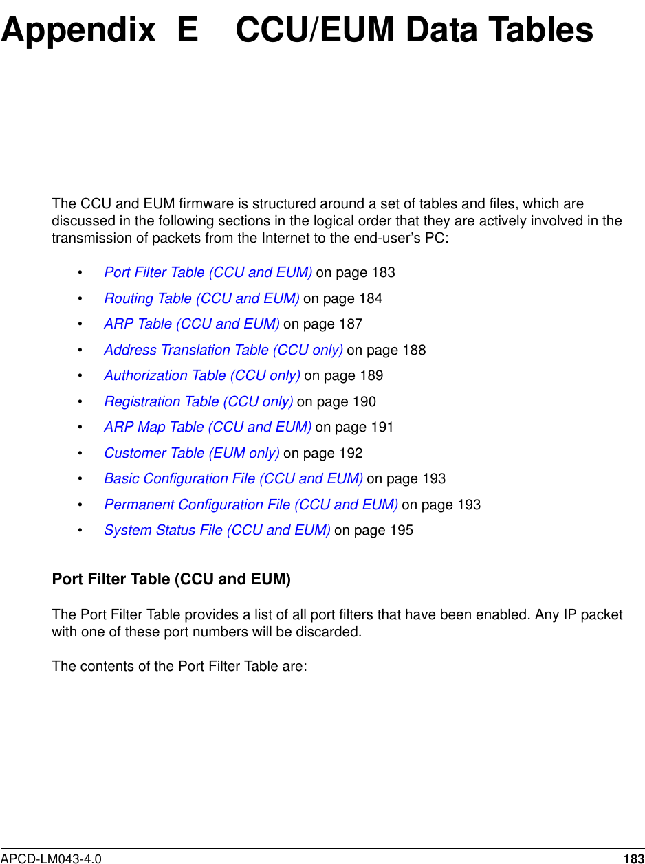

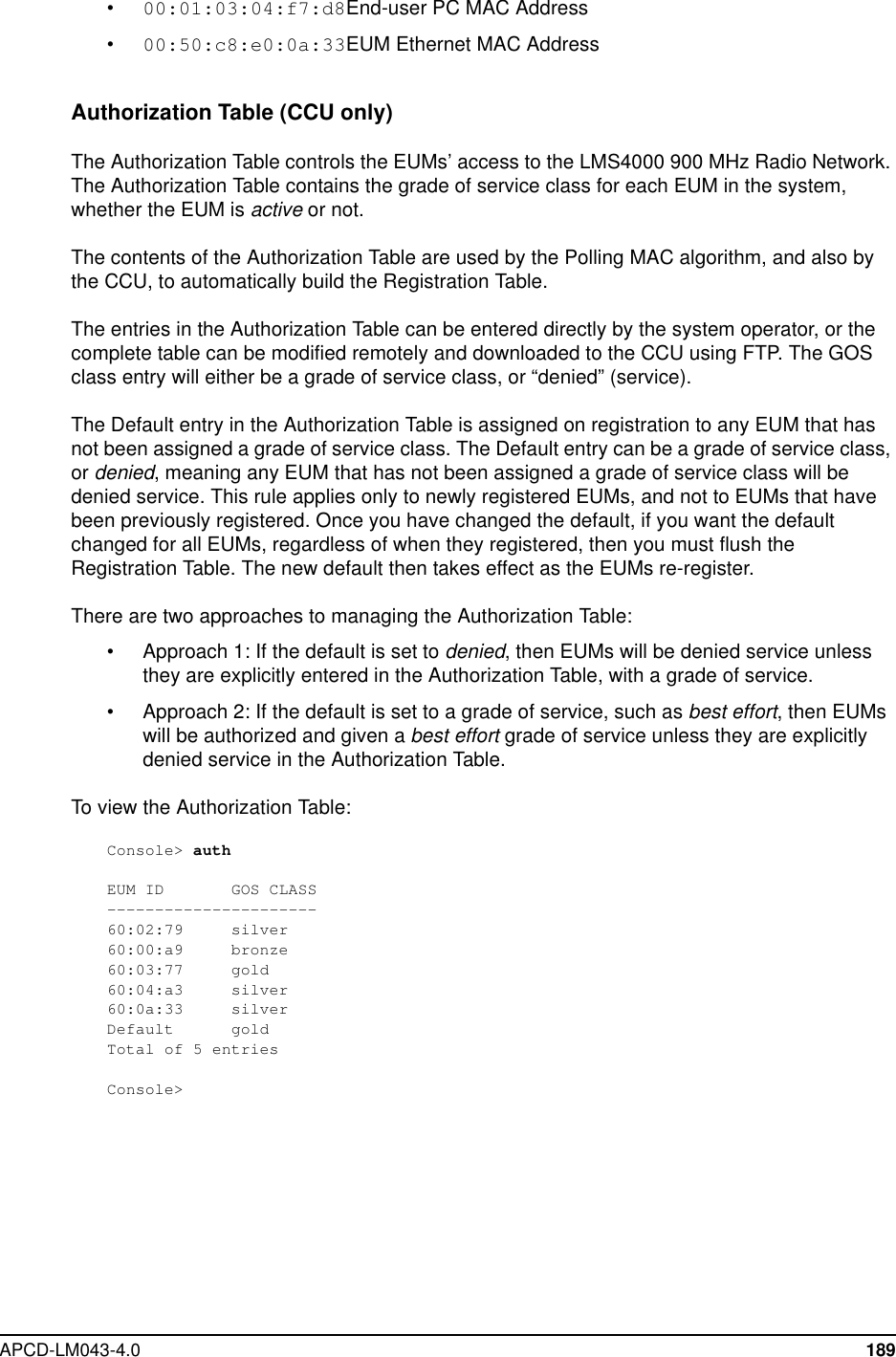
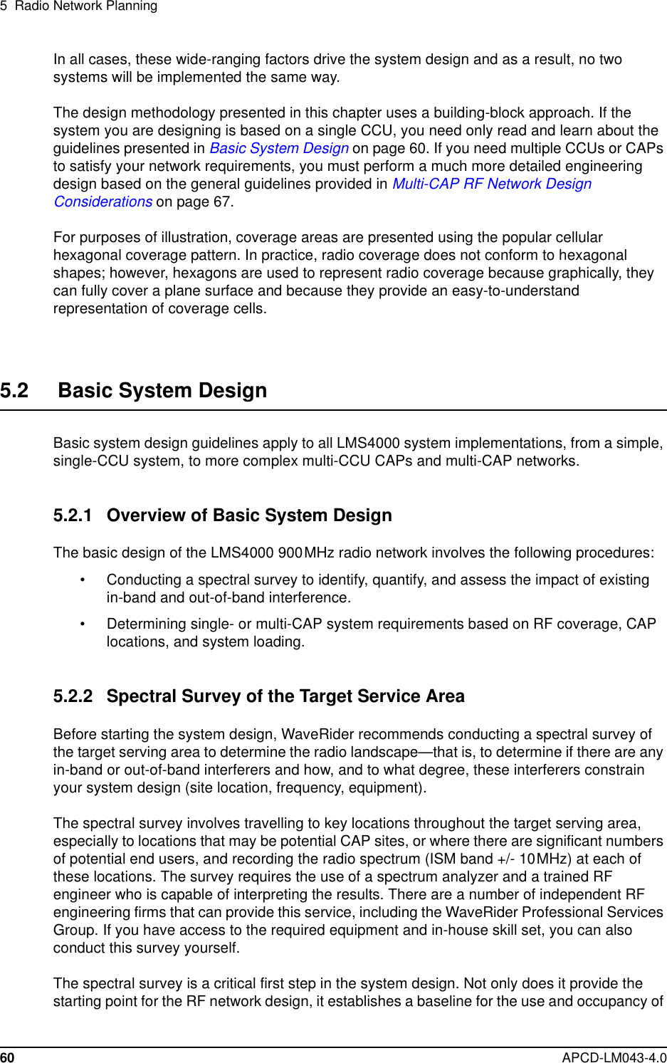
![190 APCD-LM043-4.0Registration Table (CCU only)The Registration Table contains a list of all registered EUMs. The CCU automatically buildsand adds to this table as EUMs communicate with the CCU. Every EUM that registers with theCCU appears in this table. The EUM will be removed from the Registration Table if the:• EUM has not communicated with the CCU for more than 12 hours because:• the EUM has been turned off for more than 12 hr., or• theEUMhashadnotraffictosendformorethan12hr.,or• the EUM has lost its RF connection to the CCU for more than 12 hr.• EUM does not respond to traffic from the CCU. In this case, the EUM will be removedimmediately from the Registration Table.The Registration Table contains the following entries:Table 54 Registration Table EntriesTo view the Registration Table:Console> airMaximum Associations : 75Deregistration Count : 8REGISTERED EUMsEUM ID GOS Level Time[s]--------------------------------60:03:75 gold 2260:0a:33 silver 260:00:ef gold 2960:00:46 gold 160:00:4a gold 060:00:f5 gold 152260:02:79 silver 160:03:f6 gold 160:04:a3 silver 2760:00:a9 bronze 0--------------------------------Table Entry DescriptionEUM ID EUM IDGOS Level Grade of Service ClassTime (s) Time since the last payload was received from the EUM.Maximum Associations The maximum number of EUMs that can be associated atany one instant in time.Deregistration Count An EUM will be de-registered if it does not respond afterthe CCU has sent it this many consecutive polls.](https://usermanual.wiki/Vecima-Networks/EUM3003.Users-Manual/User-Guide-299333-Page-208.png)
![192 APCD-LM043-4.0Customer Table (EUM only)The purpose of the Customer Table is to give the system operator control over the number ofPCs that can access the Internet through the EUM. The Customer Table is optimized for thecase where multiple hosts are connected to the EUM, but only one accesses the Internet atany given time. The Customer Table also acts as a bridging table, ensuring local traffic is keptlocal.The Customer Table presents a list of the end-user computers that are connected to the EUM.If customer_max is set to “1”, only one of the computers in the table will have air access. Ifcustomer_max is set to “n”, up to “n” computers in the Customer Table will have air access.Air access is assigned on a “first come, first served” basis. If n=1, the first computer to transmitpackets will be granted air access. All other computers will be denied air access. If thecomputer that has been granted air access, does not transmit traffic for 10 minutes, then hisair access will be removed and the next computer that transmits a packet will be granted airaccess.More generally, for any “n”, up to customer_max, the first n computers transmitting packets willbe granted air access and, if any of them fails to transmit traffic for 10 minutes, their air accesswill be removed, allowing the next computer without air access to be granted air access assoon as they transmit data.The contents of the Customer Table are:Table 56 Customer Table EntriesNOTE: If customer max is set to 1, and you want to connect a differentPC to the EUM, for maintenance purposes, for example, youmust clear the Customer Table, reset the EUM, or wait for 10minutes.To display the Customer Table:Console> custMAC Address Air Access Time[s]-------------------------------------------00:50:da:b7:34:f3 Y 10000:50:da:bb:d1:de N 100Total of: 2 entriesConsole>Table Entry DescriptionMAC Address Computer’s MAC addressAir Access Y - computer has been granted air access.N - computer has not been granted air accessTime (s) Time, in seconds, since the last packet was received from aparticular end-user computer or device.](https://usermanual.wiki/Vecima-Networks/EUM3003.Users-Manual/User-Guide-299333-Page-210.png)
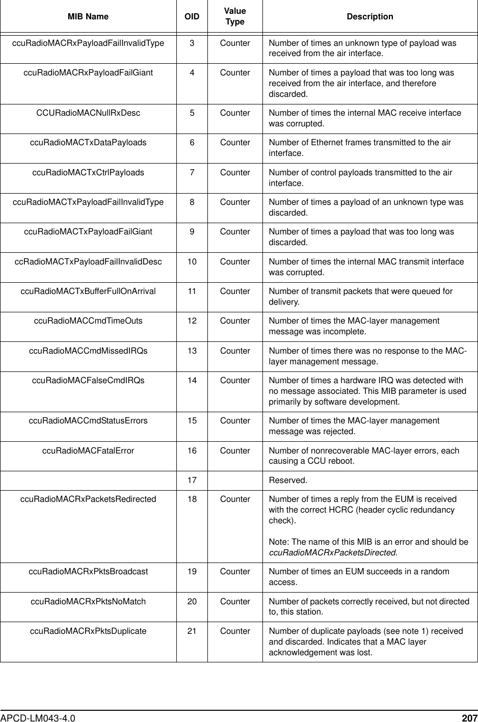


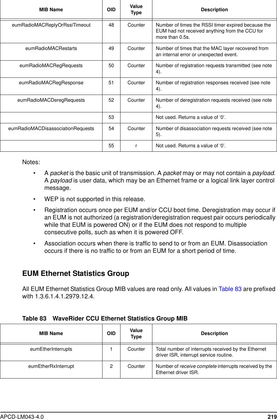
![APCD-LM043-4.0 229Atmel Fatal Error Not used.Unused Statistic Not used.rxPktsDirected 3At the CCU, the number of times a reply fromthe EUM is received with the correct HCRC(header cyclic redundancy check). In theEUM, the number of times a poll for the EUMis received from the CCU with the correctHCRC.rxPktsBroadcast 3At the CCU, the number of times an EUMsucceeds in a random access. Note that allEUM packets are directed to the CCU, notbroadcast. At the EUM, the number ofbroadcast packets (see note 1) received withthe correct HCRC. These are also randomaccess opportunities.rxPktsNoMatch 3Number of packets correctly received, but notdirected to, this station.rxPktsDuplicate 3Number of duplicate payloads (see note 1)received and discarded. Indicates that a MAClayer acknowledgement was lost.rxPktsRuntFail 3Number of packets received that were shorterthan the minimum size.rxPktsLongFail 3Number of packets received that were longerthan the maximum size.rxPktsHCRCFail 3Number of packets received with a MACheader CRC failure (header corrupted).rxPktsICVFail 3Number of packets received with anencryption (WEP, wireless equivalent privacy)keymismatch(seenote3).rxPktsFCSFail 3Number of packets received with a FrameCheck Sequence failure (payload corrupted).rxPktsAssocFail 3Number of times a received packet had to bediscarded because too many EUMs werealready associated.[CCUonly]rxPktsIncomplete 3Number of times the receive DMA for apayload does not complete (internal error).rxPayloadsFailFull 3Number of times a received payload has to bediscarded because either no receivedescriptor was available, or there was notenough buffer space.rxPayloadsDelivered 3Number of payloads that this station receivedcorrectly.Statistic Availablein MIB Description (see note 2)](https://usermanual.wiki/Vecima-Networks/EUM3003.Users-Manual/User-Guide-299333-Page-247.png)
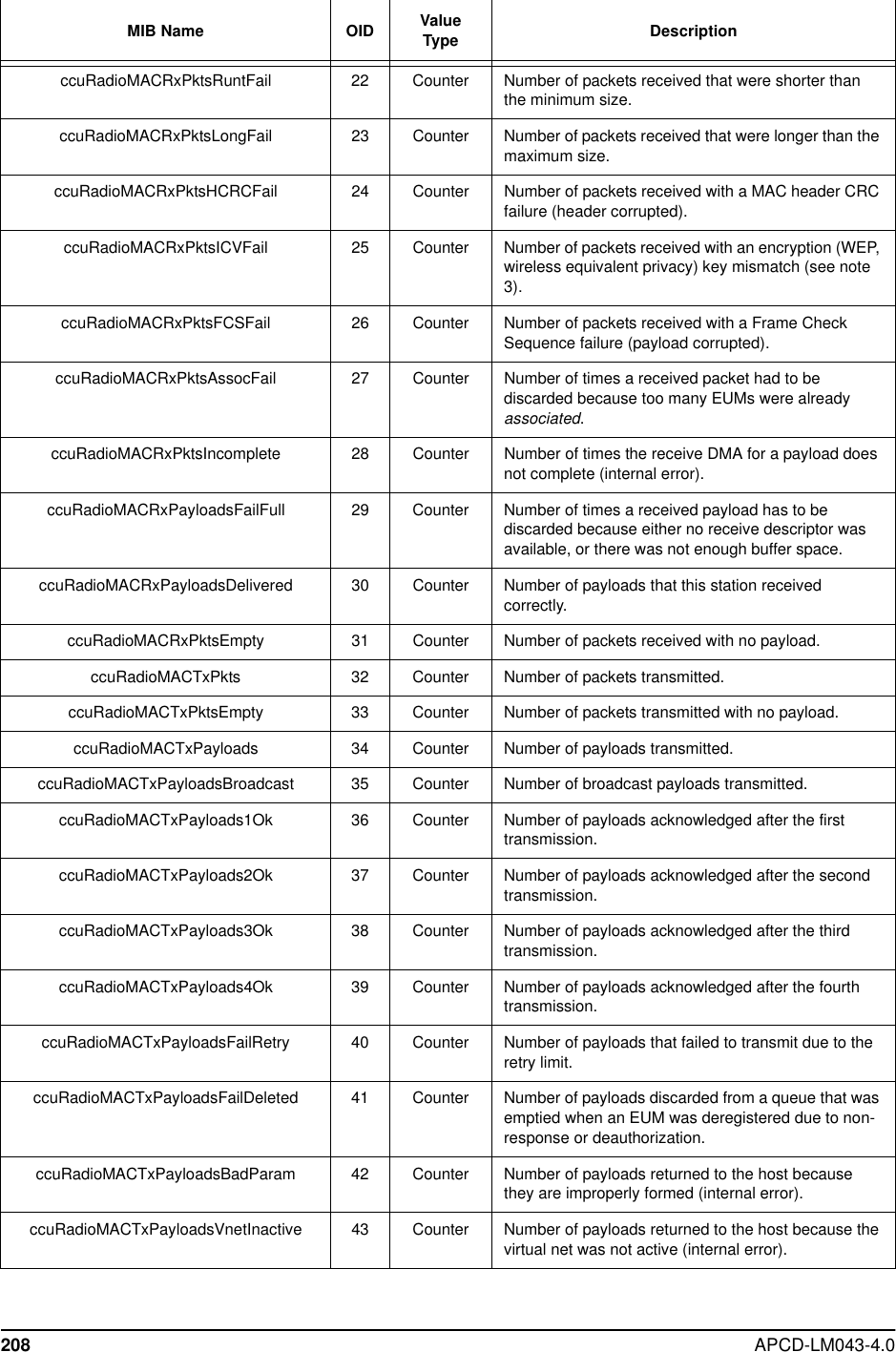
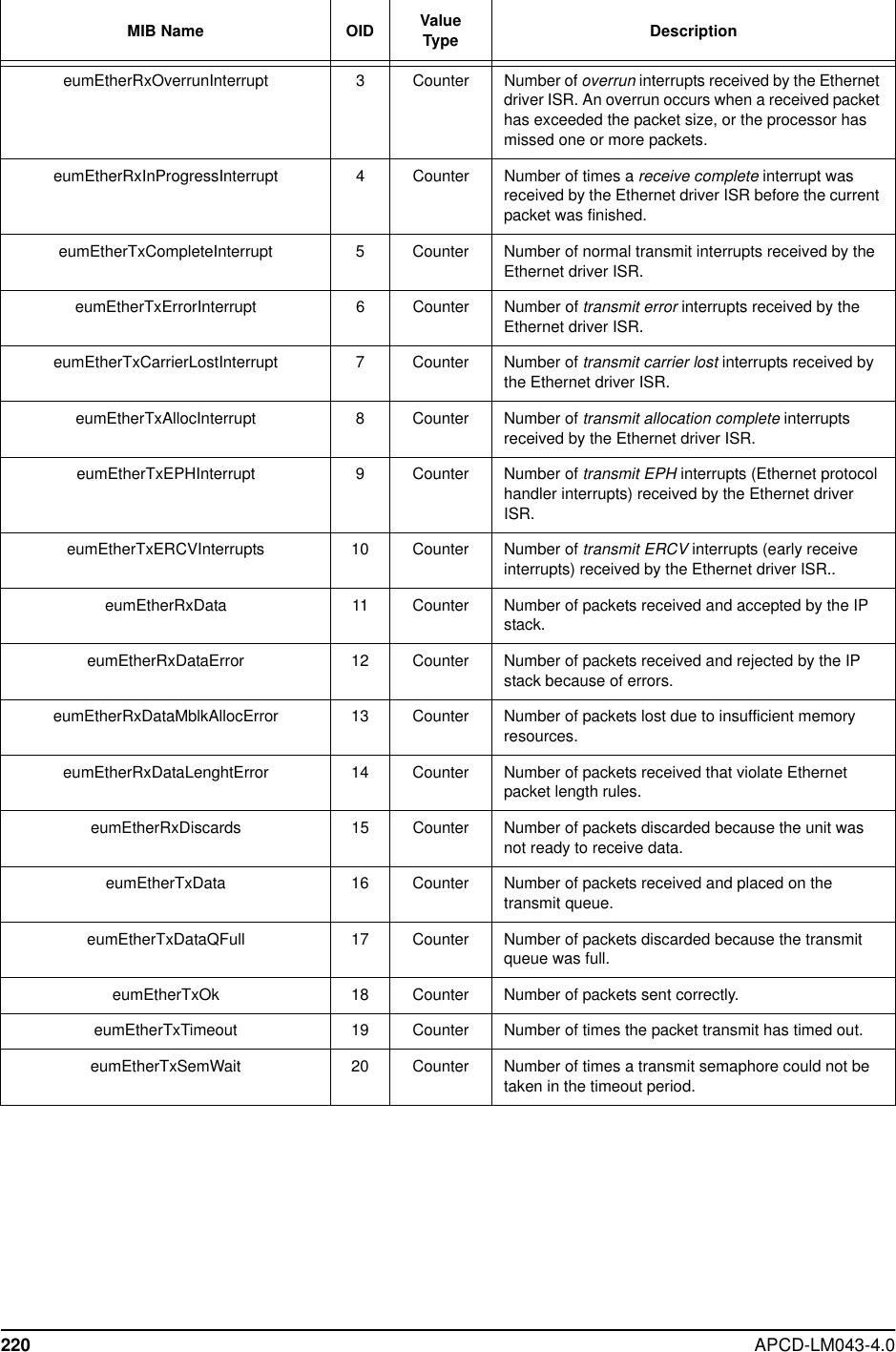
![230 APCD-LM043-4.0rxPktsEmpty 3Number of packets received that are directedto this station, but that did not contain apayload.txPkts 3Number of packets transmitted.txPktsEmpty 3Number of packets transmitted with nopayload.txPayloads 3Number of payloads transmitted.txPayloadsBCast 3Number of broadcast payloads transmitted.[CCU only]txPayloads1Ok 3Number of payloads acknowledged after thefirst transmission.txPayloads2Ok 3Number of payloads acknowledged after thesecond transmission.txPayloads3Ok 3Number of payloads acknowledged after thethird transmission.txPayloads4Ok 3Number of payloads acknowledged after thefourth transmission.txPayloadsFailRetry 3Number of payloads that failed to transmit dueto the retry limit.txPayloadsFailAssocDeleted 3Number of payloads that were discardedbecause the EUM was unreachable ordeauthorized. [CCU only]txPayloadsFailBadParam 3Number of payloads returned to the hostbecause they are improperly formed (internalerror).txPayloadsFailVnetInactive 3Number of payloads returned to the hostbecause the virtual net was not active (internalerror). [CCU only]txPayloadsFailAssocFail 3Number of payloads returned to the hostbecause too many other EUMs were alreadyassociated.[CCUonly]txPayloadsFailTimeout 3Number of payloads returned to the hostbecause of timeout.txPayloadsFailQueueTooLong 3Number of payloads returned to the hostbecause the transmit queue for the EUM wastoo long (see note 4). [CCU only]txPayloadsEmpty Not used.Statistic Availablein MIB Description (see note 2)](https://usermanual.wiki/Vecima-Networks/EUM3003.Users-Manual/User-Guide-299333-Page-248.png)
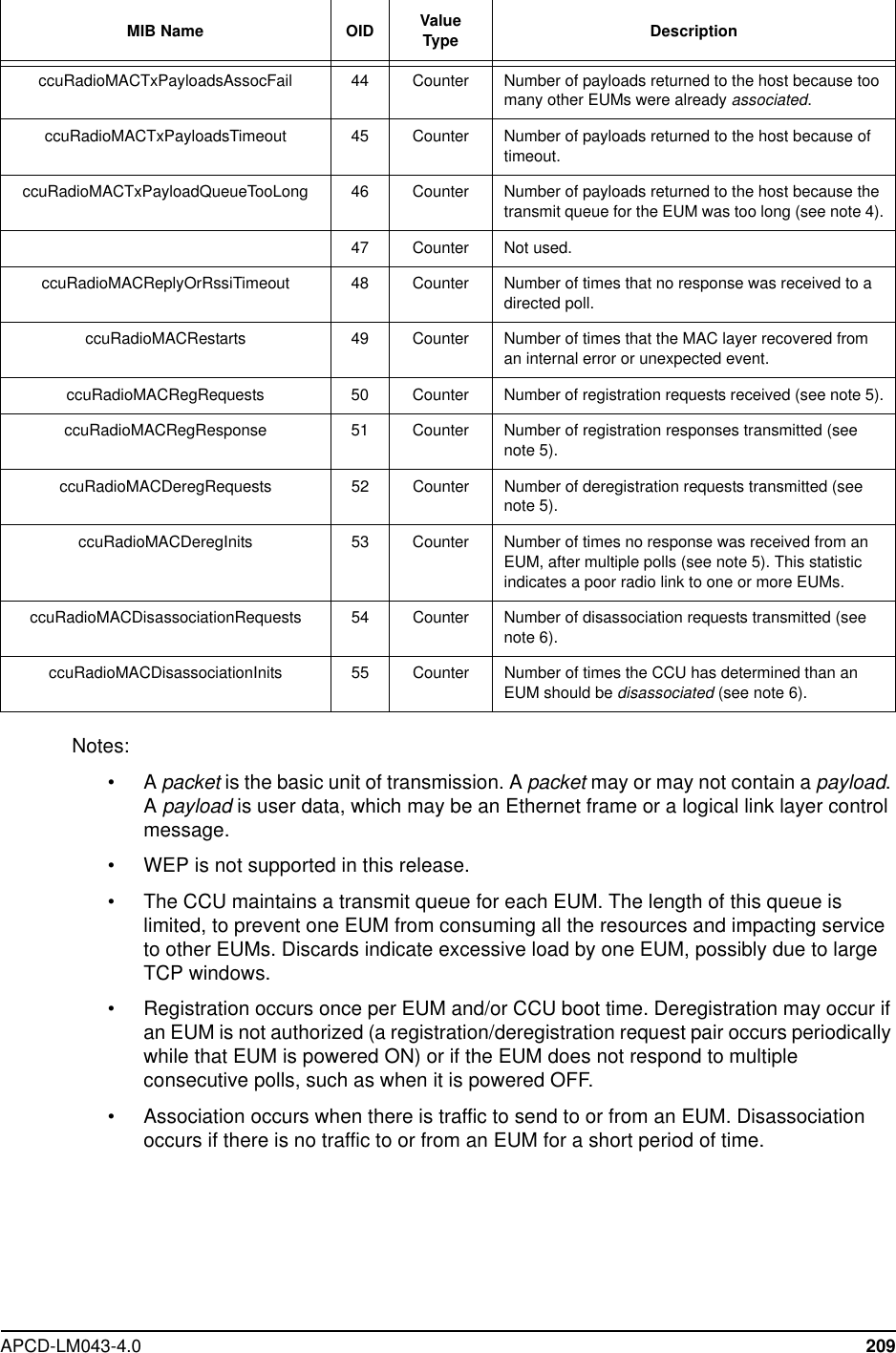
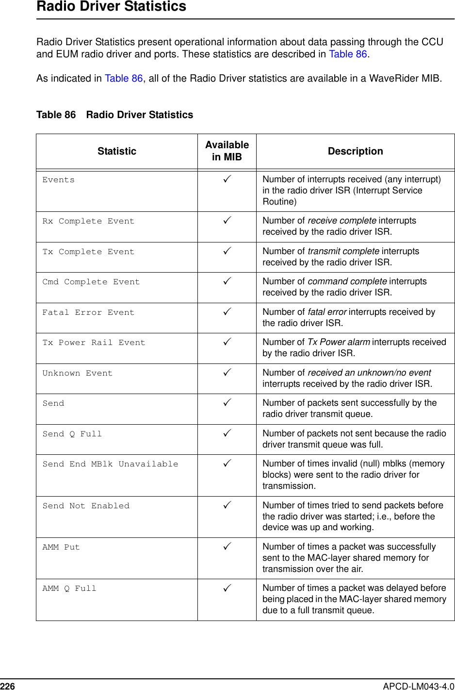
![APCD-LM043-4.0 231Notes:•Apacket is the basic unit of transmission. A packet may or may not contain a payload.Apayload is user data, which may be an Ethernet frame or a logical link layer controlmessage.• WEP is not supported in this release.replyOrRssiTimeouts 3At the CCU, the number of times that noresponse was received to a directed poll. Atthe EUM, the number of times the RSSI timerexpired because the EUM had not receivedanything from the CCU for more than 0.5s.restarts 3Number of times that a PAI (physicalattachment interface) state machine restartoccurred (internal error).registrationRequests 3At the CCU, the number of registrationrequests received (see note 5). At the EUM,the number of registration requeststransmitted (see note 5).registrationResponses 3At the CCU, the number of registrationresponses transmitted (see note 5). At theEUM, the number of registration responsesreceived (see note 5).deregistrationRequests 3At the CCU, the number of deregistrationrequests transmitted (see note 5). At the EUM,the number of deregistration requestsreceived (see note 5).deregistrationInits 3Number of times no response was receivedfrom an EUM, after multiple polls (see note 5).[CCU only]disassociationRequests 3At the CCU, the number of disassociationrequests transmitted (see note 6). At the EUM,the number of disassociation requestsreceived (see note 6).disassociationInits 3Number of times the CCU has determinedthan an EUM should be disassociated (seenote 6). [CCU only]newAssociations 3At the CCU, the number of times a newassociation is created (see note 6). At theEUM, the number of transitions to associatedstate (see note 6).currentAssociations 3Number of EUMs currently associated + 1(see note 6). The one additional association isfor “broadcast”. [CCU only]unexpectedEvents 3Number of internal unexpected events.Statistic Availablein MIB Description (see note 2)](https://usermanual.wiki/Vecima-Networks/EUM3003.Users-Manual/User-Guide-299333-Page-249.png)
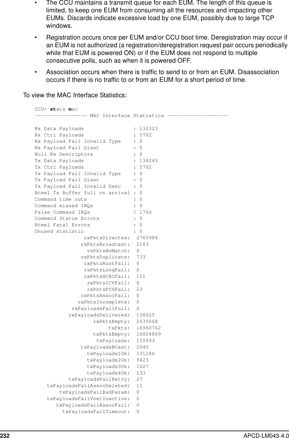
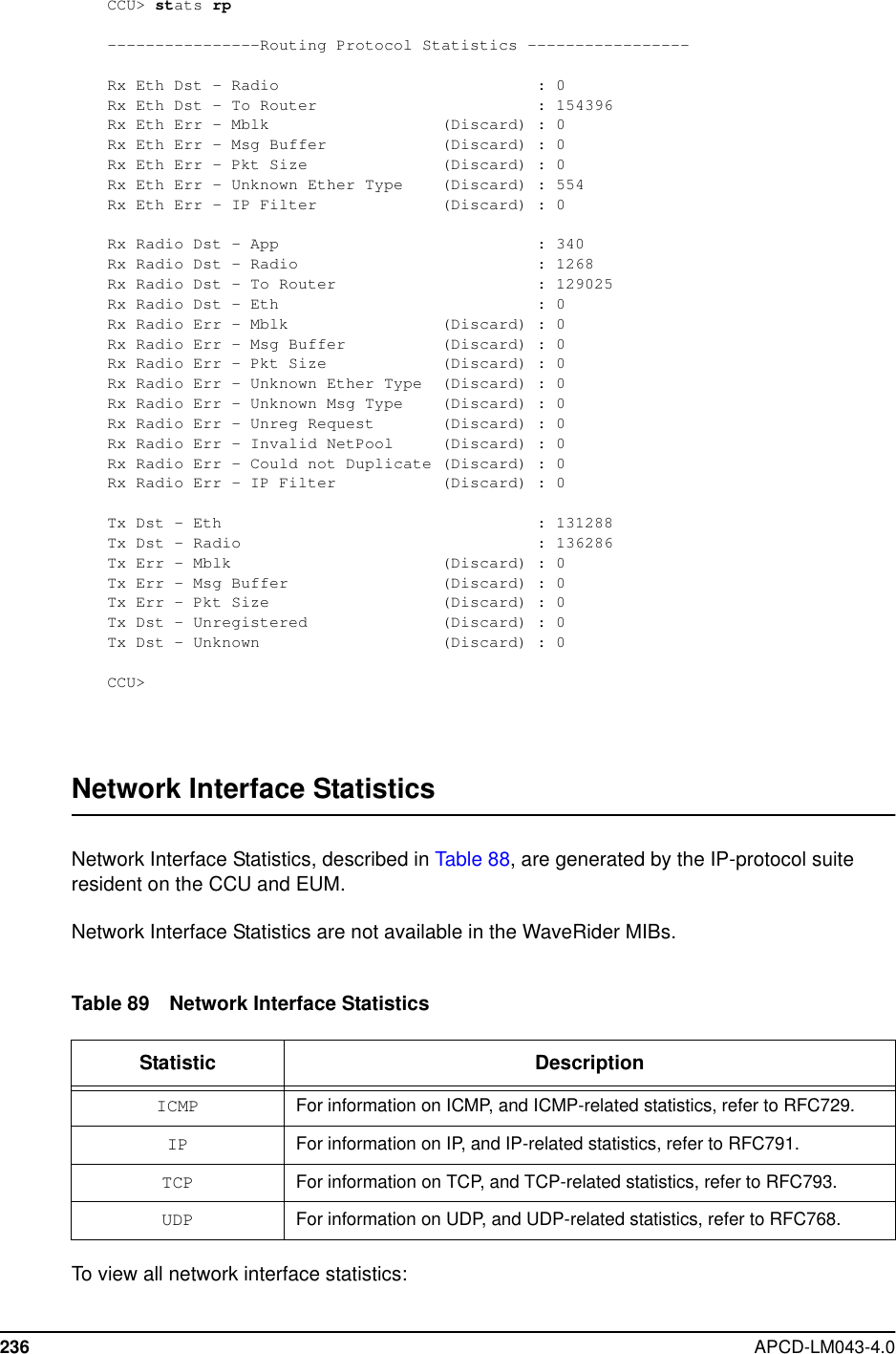
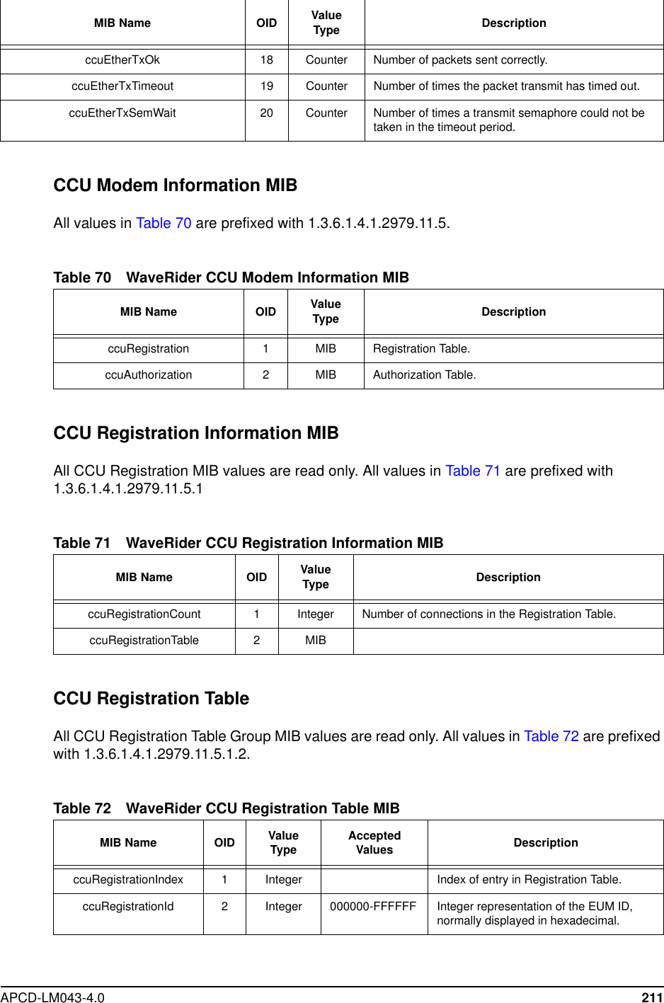
![APCD-LM043-4.0 233txPayloadsFailQueueTooLong: 0txPayloadsEmpty: 0replyOrRssiTimeouts: 232598restarts: 0registrationRequests: 0registrationResponses: 0deregistrationRequests: 0deregistrationInits: 0disassociationRequests: 5671disassociationInits: 5702newAssociations: 5671currentAssociations: 3unexpectedEvents: 0latestTx: 187latestProg: 9881latestTxPayload: 212latestReply: 9912lateReplyEum: 6294067longestSearch: 127txDescAvail: 74CCU>Routing/Bridging Protocol StatisticsRouting/Bridging Protocol Statistics present operational information about data which isprocessed by the EUM bridging or CCU routing layer. These statistics are described in Table88.The Routing/Bridging Protocol Statistics are not available in the WaveRider MIBs.Table 88 Routing/Bridging Protocol StatisticsStatistic DescriptionRx Eth Dst - App Number of received Ethernet frames transferredfrom the Ethernet port to the EUM application.[EUM only]Rx Eth Dst - Radio Number of received Ethernet frames bridgedfrom the Ethernet port to the radio port. [EUMonly]Rx Eth Dst - To Router Number of received Ethernet frames transferredfrom the Ethernet port to the CCU routerapplication. [CCU only]Rx Eth Err - Mblk Number of Ethernet frames from the Ethernetport that were discarded because of a specifictype of memory allocation error.Rx Eth Err - Msg Buffer Number of Ethernet frames from the Ethernetport that were discarded because of a specifictype of memory allocation error.](https://usermanual.wiki/Vecima-Networks/EUM3003.Users-Manual/User-Guide-299333-Page-251.png)
![234 APCD-LM043-4.0Rx Eth Err - Pkt Size Number of Ethernet frames from the Ethernetport that were discarded because the frame wastoo large or too small to decode.Rx Eth Err - Unknown Ether Type Number of Ethernet frames from the Ethernetport that were discarded because they wereneither IP nor ARP frames (example, IPX frame).Rx Eth Err - Customer Table Error Number of Ethernet frames from the Ethernetport that were discarded because the host wasnot allowed air access. [EUM only]Rx Eth Err - Invalid NetPool Number of Ethernet frames from the Ethernetport that were discarded because of a specifictype of memory allocation error. [EUM only]Rx Eth Dst - Unknown Number of Ethernet frames from the Ethernetport that were discarded because the host isknown to be on the EUM’s Ethernet side. [EUMonly]Rx Eth Err - Could not Duplicate Number of Ethernet frames from the Ethernetport that were discarded because of a specifictype of memory allocation error. [EUM only]Rx Eth Err - IP Filter Number of port-filtered Ethernet frames from theEthernet port.Rx Radio Dst - App Number of Ethernet frames that were transferredfrom the radio to the application layer.Rx Radio Dst - Radio Number of Ethernet frames that were receivedfrom the radio and transmitted back out throughthe radio (i.e., “switched”). [CCU only]Rx Radio Dst - To Router Number of Ethernet frames that were receivedfrom the radio port and forwarded to the CCUrouter application (i.e., destined for the CCUapplication or gateway). [CCU only]Rx Radio Dst - Eth Number of Ethernet frames from the radio portthat were bridged from the radio port to theEthernet port. [EUM only]Rx Radio Err - Mblk Number of Ethernet frames from the radio portthat were discarded because of a specific type ofmemory allocation error.Rx Radio Err - Msg Buffer Number of Ethernet frames from the radio portthat were discarded because of a specific type ofmemory allocation error.Rx Radio Err - Pkt Size Number of Ethernet frames from the radio portthat were discarded because the frame was toolarge or too small to decode.Rx Radio Err - Unknown Ether Type Number of Ethernet frames from the radio portthat were discarded because they were neitherIP nor ARP frames (example, IPX frame).Statistic Description](https://usermanual.wiki/Vecima-Networks/EUM3003.Users-Manual/User-Guide-299333-Page-252.png)
![APCD-LM043-4.0 235To view the Routing Protocol Statistics:Rx Radio Err - Unknown Msg Type Number of Ethernet frames from the radio portthat were discarded because of an internalrouting error.Rx Radio Err - Unreg Request Number of Ethernet frames received from theradio port that were discarded because theycame from an unregistered EUM. [CCU only]Rx Radio Err - Invalid NetPool Number of Ethernet frames received from theradio port that were discarded because of aspecific type of memory allocation error.Rx Radio Err - Could not Duplicate Number of Ethernet frames received from theradio port that were discarded because of aspecific type of memory allocation error.Rx Radio Err - Reflection Number of Ethernet frames received from theradio port that were discarded because thesource address was on the EUM (split-horizonrule). [EUM only]Rx Radio Err - IP Filter Number of port-filtered Ethernet frames from theradio port.Tx Dst - Eth Number of Ethernet frames that were transmittedthrough the Ethernet port.Tx Dst - Radio Number of Ethernet frames that were transmittedthrough the radio port.Tx Err - Mblk Number of transmit Ethernet frames that had tobe discarded because of a specific type ofmemory allocation error.Tx Err - Msg Buffer Number of transmit Ethernet frames that had tobe discarded because of a specific type ofmemory allocation error.Tx Err - Pkt Size Number of transmit Ethernet frames that had tobe discarded because the frame was too large ortoo small to decode.Tx Dst - Unregistered Number of transmit Ethernet frames that had tobe discarded because they were for anunregistered EUM. [CCU only]Tx Dst - Unknown Number of transmit Ethernet frames that had tobe discarded because the Ethernet address didnot appear in the Address Table.Tx Err - Invalid NetPool Number of transmit Ethernet frames that had tobe discarded because of a specific type ofmemory allocation error. [EUM only]Tx Err - Could not Duplicate Number of transmit Ethernet frames that had tobe discarded because of a specific type ofmemory allocation error. [EUM only]Statistic Description](https://usermanual.wiki/Vecima-Networks/EUM3003.Users-Manual/User-Guide-299333-Page-253.png)