Vecima Networks EUM3003 Wireless LAN end-user modem User Manual LMS4000 900 MHz Guide
Vecima Networks Inc. Wireless LAN end-user modem LMS4000 900 MHz Guide
Contents
- 1. Warning and Notices
- 2. Users Manual
Users Manual

LMS4000
900 MHz Radio Network
User Guide
APCD-LM043-4.0
WaveRider Communications Inc.
Software License Agreement
This is a legal agreement between you (either an individual or an entity) and WaveRider Communications Inc.
for the use of WaveRider computer software, hereinafter the “LICENSED SOFTWARE”.
By using the LICENSED SOFTWARE installed in this product, you acknowledge that you have read this
license agreement, understand it, and agree to be bound by its terms. You further agree that it is the full
and complete agreement between you and WaveRider Communications Inc., superseding all prior writ-
ten or verbal agreements of any kind related to the LICENSED SOFTWARE. If you do not understand or
do not agree to the terms of this agreement, you will cease using the LICENSED SOFTWARE immedi-
ately.
1. GRANT OF LICENSE—This License Agreement permits you to use one copy of the LICENSED
SOFTWARE.
2. COPYRIGHT—The LICENSED SOFTWARE is owned by WaveRider Communications Inc. and is
protected by copyright laws and international treaty provisions; therefore, you must treat the LICENSED
SOFTWARE like any other copyrighted material (e.g., a book or magazine). You may not copy the written
materials accompanying the LICENSED SOFTWARE.
3. LIMITS OF FEATURE AVAILABILITY—The LICENSED SOFTWARE is sold with limitations as to certain
feature availability and use. These limits are governed by the terms of the purchase agreement. Any
actions resulting in the exceeding of these limits is not permitted, and can result in unpredictable
performance.
4. OTHER RESTRICTIONS—You may not rent or lease the LICENSED SOFTWARE. You may not
reverse engineer, decompile, or disassemble the LICENSED SOFTWARE.
5. LIMITED WARRANTY—The LICENSED SOFTWARE is provided “as is” without any warranty of any kind,
either expressed or implied, including, but not limited to, the implied warranties of merchantability and
fitness for a particular purpose. The entire risk as to the quality and performance of the LICENSED
SOFTWARE is with you, the licensee. If the LICENSED SOFTWARE is defective, you assume the risk
and liability for the entire cost of all necessary repair, service, or correction.
Some states/jurisdictions do not allow the exclusion of implied warranties, so the above
exclusion may not apply to you. This warranty gives you specific legal rights, and you may
have other rights, which vary from state/jurisdiction to state/jurisdiction.
WaveRider Communications Inc. does not warrant that the functions contained in the
LICENSED SOFTWARE will meet your requirements, or that the operation of the
LICENSED SOFTWARE will be error-free or uninterrupted.
6. NO OTHER WARRANTIES—To the maximum extent permitted by applicable law, WaveRider
Communications Inc. disclaims all other warranties, either express or implied, including, but not limited to,
the implied warranties of merchantability and fitness for a particular purpose, with regard to the
LICENSED SOFTWARE and the accompanying written materials.
7. NO LIABILITY FOR CONSEQUENTIAL DAMAGES—To the maximum extent permitted by applicable law,
in no event shall WaveRider Communications Inc. or its suppliers be liable for any damages whatsoever
(including, without limitation, damages for loss of business profits, business interruption, loss of business
information, or any other pecuniary loss) arising from the use of or inability to use the LICENSED
SOFTWARE, even if WaveRider Communications Inc. has been advised of the possibility of such
damages, or for any claim by any other party.
Because some states/jurisdictions do not allow the exclusion or limitation of liability for
consequential or incidental damages, the above limitation may not apply to you.
In no event will WaveRider’s liability exceed the amount paid for the LICENSED
SOFTWARE.
The following are trademarks or registered trademarks of their respective companies
or organizations:
Microsoft Windows NT 4.0 Workstation (with Service Pack 6a), Microsoft Access,
Microsoft SQL Server, Microsoft SQL Agent / Microsoft Corporation
Vircom VOP Radius Server / Vircom Inc.
Castlerock SNMPc Server / Castle Rock Computing
APS PowerChute PLUS / American Power Conversion
Veritas Backup Exec / VERITAS Software
© 2002 by WaveRider Communications Inc. All rights
reserved. This manual may not be reproduced by any means
in whole or in part without the express written permission of
WaveRider Communications Canada Inc.
ISSUE 4.0, April 2002
Warranty
In the following warranty text, “WaveRider®” shall mean WaveRider Communications Inc.
This WaveRider product is warranted against defects in material and workmanship for a period of one (1)
year from the date of purchase. During this warranty period WaveRider will, at its option, either repair or
replace products that prove to be defective.
For warranty service or repair, the product must be returned to a service facility designated by WaveR-
ider. Authorization to return products must be obtained prior to shipment. The WaveRider RMA number
must be on the shipping documentation so that the service facility will accept the product. The buyer shall
pay all shipping charges to WaveRider and WaveRider shall pay shipping charges to return the product
to the buyer within Canada or the USA. For all other countries, the buyer shall pay shipping charges as
well as duties and taxes incurred in shipping products to or from WaveRider.
WaveRider warrants that the firmware designed by it for use with the unit will execute its programming
instructions when properly installed on the unit. WaveRider does not warrant that the operation of the unit
or firmware will be uninterrupted or error-free.
Limitation of Warranty
The foregoing warranty shall not apply to defects resulting from improper or inadequate maintenance by
the buyer, buyer-supplied interfacing, unauthorized modification or misuse, operation outside the envi-
ronmental specifications for the product, or improper site preparation or maintenance. No other warranty
is expressed or implied. WaveRider specifically disclaims the implied warranties of merchantability and
fitness for any particular purpose.
No Liability for Consequential Damages
To the maximum extent permitted by applicable law, in no event shall WaveRider or its suppliers be liable
for any damages whatsoever (including, without limitation, damages for loss of business profits, business
interruption, loss of business information, or any other pecuniary loss) arising from the use of or inability
to use the product, even if WaveRider has been advised of the possibility of such damages, or for any
claim by any other party.
Because some states/jurisdictions do not allow the exclusion or limitation of liability for consequential or
incidental damages, the above limitation may not apply to you.
In no event will WaveRider’s liability exceed the amount paid for the product.
Regulatory Notices
This equipment has been tested and found to comply with the limits for a Class B Intentional Radiator,
pursuant to Part 15 of the FCC Regulations and RSS-210 of the IC Regulations. These limits are
intended to provide protection against harmful interference when the equipment is operated in a residen-
tial environment.
This equipment generates, uses, and can radiate radio frequency energy and, if not installed and used in
accordance with the instruction manual, may cause harmful interference to radio communications. How-
ever, there is no guarantee that interference will not occur in a particular installation.
Notice to User
Any changes or modifications to equipment that are not expressly approved by the manufacturer may
void the user’s authority to operate the equipment.

APCD-LM043-4.0 v
Contents
Contents.................................................................v
Figures ..................................................................ix
Tables...................................................................xi
Preface .................................................................xv
1 Introduction . . . . . . . . . . . . . . . . . . . . . . . . . . . . . . . . . . . . . . . . . . . . . . . . 1
2QuickStartup ...............................................5
2.1Equipment...........................................................5
2.2EquipmentSetup .....................................................6
2.3CCUConfiguration....................................................7
2.4EUMConfiguration....................................................8
2.5TestingCCU–EUMCommunications......................................9
2.6ConnectingtheQuickStartuptotheInternet...............................11
2.7AddingmoreEUMstotheQuickStartup ..................................12
3DetailedDescription ........................................13
3.1LMS4000Overview...................................................13
3.2CommunicationsAccessPoint..........................................14
3.2.1KeyComponents...............................................14
3.2.2OptionalComponents ...........................................17
3.3Customer-premisesEquipment .........................................18
3.3.1KeyComponents...............................................18
3.3.2EUM ........................................................19
3.4BasicOperation .....................................................22
3.4.1LMS4000TransmissionConcept ..................................22
3.4.2CCUandEUMConfiguration .....................................22
3.4.3LMS4000ProtocolStacks........................................24
3.4.4BasicDataTransmission ........................................24
3.5 CCU–EUM Interface — Detailed Technical Description. . . . . . . . ...............28
3.5.1PhysicalLayer(DSSSRadio) .....................................28
3.5.2MACLayer(PollingMAC) ........................................36
3.6CCUandEUMFeatureDescription......................................48
3.6.1DHCPRelay ..................................................48
3.6.2PortFiltering ..................................................49
3.6.3SNTP/UTCTimeClock ..........................................50
3.6.4CustomerList .................................................51
3.6.5 SNMP Support . . . . ............................................51
4IPNetworkPlanning ........................................53
4.1LMS4000IPAddressing...............................................53
4.2IPPlanningProcess..................................................55

vi APCD-LM043-4.0
4.3NetworkAddressTranslation .......................................... 57
5RadioNetworkPlanning.....................................59
5.1DesignMethodology................................................. 59
5.2BasicSystemDesign ................................................ 60
5.2.1OverviewofBasicSystemDesign..................................60
5.2.2SpectralSurveyoftheTargetServiceArea ..........................60
5.2.3In-bandInterference ............................................61
5.2.4Out-of-bandInterference .........................................61
5.2.5UsingBandpassFiltersatCAPSites ...............................63
5.2.6Single-orMulti-CAPImplementation................................64
5.3Multi-CAPRFNetworkDesignConsiderations............................. 67
5.3.1Multi-CAPNetworkDesignProcess ................................67
5.3.2FrequencySelection—StandardFrequencySet ......................67
5.3.3C/IRequirements...............................................68
5.3.4DealingwithExternalInterference..................................69
5.3.5VerifyingtheDesign ............................................69
5.3.6SummaryofRFDesignGuidelines .................................71
6 Installation/Diagnostic Tools . . . . . . . . . . . . . . . . . . . . . . . . . . . . . . . . . 73
6.1IndicatorsandConnectors ............................................ 74
6.1.1NetworkLED ..................................................75
6.1.2RadioLED ....................................................75
6.1.3PowerLED ...................................................75
6.1.4EthernetLEDs .................................................76
6.2Command-lineInterface .............................................. 76
6.3EUMConfigurationUtility ............................................. 77
6.4RSSI/TxQuality/AntennaPointing ...................................... 77
6.5TransferaFiletoorfromaCCUUsingFTP............................... 78
6.6OperatingStatistics.................................................. 79
6.7SNMP ............................................................ 80
6.8FieldUpgradeProcess............................................... 80
6.9FTPingCCUandEUMConfigurationFiles................................ 81
7ConfiguringtheCCU........................................83
7.1CCUandEUMSerialNumber,MACAddress,andStationID................. 84
7.2SettingtheCCUPassword............................................ 84
7.3ConfiguringtheCCURFParameters.................................... 85
7.4ConfiguringCCUIPParameters........................................ 86
7.5 Configuring DHCP Relay. . . . . . ........................................ 88
7.6ConfiguringPortFiltering.............................................. 89
7.7ConfiguringtheSNTP/UTCTimeClock .................................. 90
7.8ConfiguringSNMP................................................... 93
7.9AddingEUMstotheAuthorizationTable ................................. 95
8ConfiguringtheEUM .......................................97
8.1SettingtheEUMPassword............................................ 98
8.2ConfiguringtheEUMRFParameters.................................... 98
8.3ConfiguringEUMIPParameters........................................ 99
8.4ConfiguringPortFiltering............................................. 101

APCD-LM043-4.0 vii
8.5ConfiguringSNMP ..................................................102
8.6ConfiguringtheCustomerList .........................................104
9 Installing the EUM . . . . . . . . . . . . . . . . . . . . . . . . . . . . . . . . . . . . . . . . . 105
9.1BeforeyouStarttheEUMInstallation....................................105
9.2OtherEUMProgrammingConsiderations ................................106
9.3InstallationOverview.................................................106
9.4InstallationProcedures...............................................107
9.4.1OpeningtheBox ..............................................107
9.4.2TurningofftheEnd-user’sCordlessPhones ........................108
9.4.3ChoosingaLocationfortheEUMandAntenna ......................108
9.4.4ConnectingtheEUMComponents ................................108
9.4.5ConductingaPreliminaryCheckoftheEUM ........................110
9.4.6PositioningtheAntenna ........................................111
9.4.7MountingtheAntenna..........................................112
9.4.8ConnectingtheEnd-user’sPC ...................................115
9.4.9ObtainingValidIPAddressesfortheEnd-user’sPC ..................116
9.4.10TestingtheDataLink .........................................116
9.4.11ConfiguringtheBrowserApplication ..............................119
9.4.12CompletingtheInstallation .....................................120
9.4.13BaseliningtheInstallation ......................................120
9.4.14 Troubleshooting . . ...........................................121
10MaintainingtheNetwork ...................................125
11MonitoringtheNetwork....................................127
11.1CCUTransmitStatistics.............................................127
11.2CCUReceiveStatistics..............................................131
11.3EUMStatisticsMonitoring............................................132
11.3.1EUMTransmitStatistics .......................................132
11.3.2EUMReceiveStatistics........................................133
11.3.3UserData ..................................................134
12 Troubleshooting . . . . . . . . . . . . . . . . . . . . . . . . . . . . . . . . . . . . . . . . . 135
12.1EUMTroubleshooting...............................................136
12.2CCUTroubleshooting...............................................145
12.3IfYouHaveanInterferer.............................................149
12.4GeneralTroubleshootingInformation...................................151
13SpecializedApplications...................................155
13.1EUMThinRoute...................................................155
13.2EUMBackhaul ....................................................156

viii APCD-LM043-4.0
Appendix A Specifications .............................................157
Appendix B FactoryConfiguration .......................................159
Appendix C Command-LineSyntax ......................................163
Appendix D AntennaGuidelines.........................................181
Appendix E CCU/EUM Data Tables . . . . . . . . . . . . . . . ........................183
Appendix F PingCommands ...........................................197
Appendix G SNMPMIBDefinitions .......................................199
Appendix H OperatingStatistics.........................................223
Appendix I IPPlan—Example .........................................241
Appendix J AcronymsandGlossary .....................................253
Index ..................................................................261

APCD-LM043-4.0 ix
Figures
Figure1 QuickStartup—CCUConfiguration...............................6
Figure2 QuickStartup—EUMConfiguration ..............................8
Figure3 QuickStartup—PingTest(fromconsoleport) ......................9
Figure4 QuickStartup—PingTest(fromEUMEthernetport) ................10
Figure5 QuickStartup—ConnectingtotheInternet ........................11
Figure6 LMS4000System ............................................14
Figure7 CCU ......................................................15
Figure8 CCUFunctionalBlocks ........................................15
Figure9 CCUShelf ..................................................16
Figure10 RFSM .....................................................18
Figure11 EUM ......................................................19
Figure 12 WaveRider Indoor Directional Antenna with Switched-beam Diversity . . . . 20
Figure 13 WaveRider Switched-beam Diversity Antenna — Beam Patterns . . . . . . . 21
Figure14 LMS4000TransmissionConcept ................................22
Figure15 LMS4000ProtocolStacks......................................24
Figure16 AddressingofIPPackets ......................................26
Figure17 DeterminationofLowestandHighestChannel......................28
Figure18 EffectofDespreading .........................................30
Figure19 TypicalNLOSPath ...........................................32
Figure20 ExamplesofRadioPaths ......................................33
Figure21 PathLossCalculation .........................................34
Figure22 EUMStateDiagram ..........................................36
Figure 23 Net Throughput per EUM — 100 EUMs, 60 kbyte HTTP every 2 minutes . 43
Figure 24 Associated EUMs — 100 EUMs, 60 kbyte HTTP every 2 minutes . . . . . . . 44
Figure 25 Net Throughput per EUM — 300 EUMs, 60 kbyte HTTP every 2 minutes . 45
Figure 26 Associated EUMs — 300 EUMs, 60 kbyte HTTP every 2 minutes . . . . . . . 45
Figure 27 DHCP Relay . . . . ............................................49
Figure28 SNTP/GMTTimeClock........................................50
Figure29 LMS4000Subnets............................................54
Figure30 ExampleofaSpectralSweep ...................................62
Figure 31 Network Design in the Presence of Out-of-band Interference . . . . . . . . . . 63
Figure32 Corner-andCenter-illuminatedcells..............................65
Figure33 SectoredCell................................................66

xAPCD-LM043-4.0
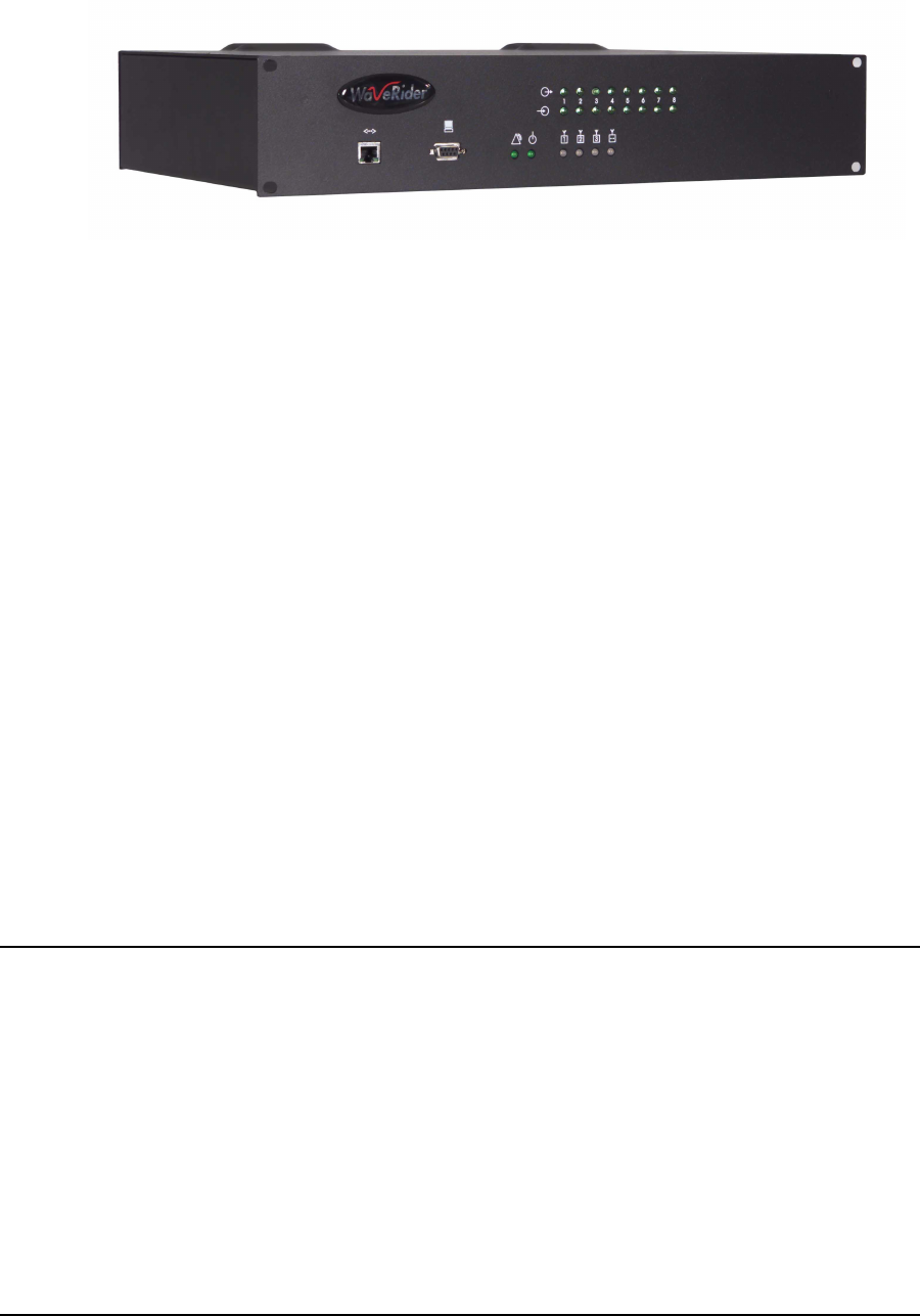
Figure34 EUMLEDsandConnectors.....................................74
Figure35 CCULEDsandConnectors.....................................74
Figure36 EthernetLEDs ...............................................76
Figure37 EUMComponents ...........................................107
Figure 38 Connecting the EUM Components . . . . . . ........................109
Figure39 ConnecttheDCPowerCordtotheEUM .........................109
Figure40 ConnecttheACPowerCord ...................................110
Figure41 EUMLEDs.................................................110
Figure 42 Preliminary Orientation of the Antenna (Top View) . . . . . . . ...........111
Figure43 RearViewofAntennaBracket..................................112
Figure 44 Antenna Bracket Components . . . . . . . . . . ........................113
Figure45 MountingtheAntennaintheBracket.............................114
Figure46 ConnectingtheEnd-user’sPC .................................115
Figure47 SampleConfiguration—TestingtheDataLink.....................117
Figure48 EthernetPlug(BottomView) ...................................152
Figure49 UsinganEUMforThinRoute ..................................155
Figure50 UsinganEUMforBackhaul....................................156
Figure51 CCUMIBs .................................................203
Figure52 EUMMIBs .................................................213

APCD-LM043-4.0 xi
Tables
Table1 ConsoleSettings ..............................................6
Table2 QuickStartup—EUMAddresses................................12
Table3 CCUConfiguration ...........................................23
Table4 EUMConfiguration ...........................................23
Table5 End-userPCConfiguration .....................................24
Table6 LMS4000900MHzRadioNetworkChannelization...................29
Table7 TypicalRadioCoverage .......................................35
Table8 FactoryDefaultGOSConfigurationFile ...........................41
Table9 FactoryConfiguredCommunityStrings ...........................51
Table 10 Example — CCU Radio Subnet IP Addressing . . . . . . . ...............56
Table 11 Standard Frequency Set . . . . . . . . . . . ............................68
Table12 RequiredC/IRatioforMulti-CAPDesign ..........................68
Table13 SampleFrequencyPlan—Multi-CAPDesign ......................69
Table14 SummaryofRFDesignGuidelines...............................71
Table15 NetworkLED ................................................75
Table16 RadioLED..................................................75
Table17 PowerLED .................................................75
Table18 EthernetLEDs...............................................76
Table19 ConsoleSettings.............................................77
Table20 FTPingConfigurationFiles .....................................81
Table21 RadioLEDStatusDisplays ....................................111
Table22 AntennaMountGuidelines ....................................112
Table23 SurfaceMountingOptionsfortheAntenna ........................113
Table24 EthernetLEDStatusDisplays..................................115
Table25 TemperatureandHumidityRequirements ........................125
Table26 PossibleTransmissionOutcomes...............................128
Table27 TypicalCCUTransmitStatistics ................................129
Table28 TypicalCCUReceiveStatistic .................................131
Table29 EUMTransmitStatistics ......................................132
Table 30 Remote Troubleshooting — EUM (Service Not Available) . . . . . . . . . . . . 138
Table31 RemoteTroubleshooting—EUM(ServiceDegraded) ...............139
Table32 LocalTroubleshooting—EUM(ServiceNotAvailable) ..............140
Table33 LocalTroubleshooting—EUM(ServiceDegraded) .................142

xii APCD-LM043-4.0
Table 34 Remote Troubleshooting — CCU . . . . . . . ........................146
Table35 LocalTroubleshooting—CCU .................................147
Table36 GeneralNetworkProblems ....................................151
Table37 EthernetCablingProblems ....................................152
Table38 RadioSpecifications .........................................157
Table39 EthernetInterfaceSpecifications ...............................158
Table 40 Power Supply Specifications . . . . . . . . . . ........................158
Table41 EnvironmentalSpecifications ..................................158
Table42 CCUFactoryConfiguration ....................................159
Table43 EUMFactoryConfiguration ....................................160
Table44 Command-LineSyntaxConventions .............................164
Table45 Command-LineShortcutsandGettingHelp .......................164
Table46 CCUCommand-LineSyntax ..................................165
Table47 EUMCommand-LineSyntax ...................................174
Table 48 CCU, EUM Supported Antennas . . . . . . . . ........................181
Table49 PortFilterTableEntries.......................................184
Table50 BasicCCURoutes...........................................184
Table51 RoutingTableEntries ........................................185
Table52 RoutingTableFlags. .........................................186
Table53 ARPTableEntries ...........................................187
Table54 RegistrationTableEntries .....................................190
Table55 ARPMAPTableEntries ......................................191
Table56 CustomerTableEntries.......................................192
Table57 RSSI/RSSCross-referenceforSampleUnit(at915MHz) ............195
Table58 WindowsPingTestCommandOptions...........................197
Table59 GroupsinMIB-II.............................................199
Table 60 MIB-II Interface List Header MIB . . . . . . . . ........................200
Table61 MIB-IIInterfaceListTableMIB .................................200
Table62 WaveRiderCCUBaseMIB ....................................203
Table63 WaveRiderCCUGeneralInformationEnterpriseMIBs...............204
Table64 WaveRiderCCURadioConfigurationEnterpriseMIBs...............204
Table65 WaveRiderCCURadioStatisticsMIB............................205
Table66 WaveRiderCCURadioGeneralStatisticsGroupMIB ...............205
Table67 WaveRiderCCURadioDriverStatisticsGroupMIB .................205
Table68 WaveRiderCCURadioMACStatisticsGroupMIB..................206
Table69 WaveRiderCCUEthernetStatisticsGroupMIB ....................210
Table70 WaveRiderCCUModemInformationMIB.........................211
Table71 WaveRiderCCURegistrationInformationMIB .....................211

APCD-LM043-4.0 xiii
Table72 WaveRiderCCURegistrationTableMIB .........................211
Table73 WaveRiderCCUAuthorizationTableMIB ........................212
Table74 WaveRiderCCUAuthorizationTableMIB ........................212
Table75 CCURFCMIB-IITraps .......................................212
Table76 WaveRiderEUMBaseMIB....................................213
Table77 WaveRiderEUMGeneralInformationEnterpriseMIBs ..............214
Table78 WaveRiderEUMRadioConfigurationEnterpriseMIBs ..............214
Table79 WaveRiderEUMRadioStatisticsMIB ...........................215
Table80 WaveRiderEUMRadioGeneralStatisticsGroupMIB ...............215
Table81 WaveRiderEUMRadioDriverStatisticsGroupMIB.................215
Table82 WaveRiderEUMRadioMACStatisticsGroupMIB .................216
Table83 WaveRiderCCUEthernetStatisticsGroupMIB ....................219
Table84 EUMRFCMIB-IITraps .......................................221
Table85 EthernetStatistics ...........................................224
Table86 RadioDriverStatistics........................................226
Table87 MACInterfaceStatistics ......................................228
Table88 Routing/BridgingProtocolStatistics .............................233
Table89 NetworkInterfaceStatistics....................................236
Table90 LoadStatistics(RadioMeter) ..................................239
Table91 Example-CCUEthernetSubnetData ...........................241
Table92 Example-NAPIPAddressingPlan .............................241
Table93 Example-CCUEthernetIPAddressingPlan ......................242
Table94 Example-CCURadioSubnetData .............................243
Table95 Example-CCURadioIPAddressingPlan ........................243
Table96 Example-EUMSubnetData ..................................245
Table97 Example-EUMIPAddressingPlan .............................245
Table98 Example-SubscriberSubnetData..............................248
Table99 Example-SubscriberIPAddressingPlan ........................248
Table100 AcronymsandAbbreviations ..................................253
Table101 LMS4000NetworkGlossary ...................................256
—This page is intentionally left blank —

APCD-LM043-4.0 xv
Preface
About this Manual
WaveRider recommends that you read the following sections before proceeding with the
instructions in this guide:
•Software License Agreement on page ii
•Warranty on page iv
•Warnings and Advisories on page xvii
•Conventions on page xv
NOTE: The information contained in this manual is subject to change
without notice. The reader should consult the WaveRider web
site for updates.
The procedures in this document are centered around the command-line interface (CLI). For
information about configuring and operating the CCU and EUM using the WaveRider
Configuration Utility refer to the CCU/EUM Configuration Utility User Guide (APCD-LM030).
Conventions
The following conventions are used throughout this document:
WARNING!
Whenever you see this icon and heading, the associated text
addresses or discusses a critical safety or regulatory issue.
CAUTION: Whenever you see this icon and heading, the
associated text discusses an issue, which, if not followed, could
result in damage to, or improper use of, the equipment or
software.
TIP: Whenever you see this icon and heading, the associated
text provides a tip for facilitating the installation, testing, or
operation of the equipment or software

xvi APCD-LM043-4.0
Regulatory Notices
This device has been designed to operate with several different antenna types. The gain of
each antenna type shall not exceed the maximum antenna system gain as given in Appendix
Donpage181. Antennas having a higher gain are strictly prohibited by Industry Canada and
FCC regulations. The required antenna impedance is 50 ohms.
Industry Canada
CCU and EUM
The IC Certification Number for the CCU and EUM is 3225104140A.
Operators must be familiar with IC RSS-210 and RSS-102. The CCU and EUM have
been designed and manufactured to comply with IC RSS-210 and RSS-102.
Federal Communications Commission
CCU and EUM
The CCU and EUM have been designed and manufactured to comply with
FCC Part 15.
Operators must be familiar with the requirements of the FCC Part 15 Regulations prior
to operating any link using this equipment. For installations outside the United States,
contact local authorities for applicable regulations.
The FCC ID for the CCU and EUM equipment is OOX-LMS3000.
The transmitter of this device complies with Part 15.247 of the FCC Rules.
The CCU and EUM (with outdoor antenna only) must be professionally installed.
Interference Environment
Operation is subject to the following conditions:
• This device may not cause harmful interference and,
• This device must accept any interference received, including interference that
might cause undesired operation.

APCD-LM043-4.0 xvii
Operational Requirements
CCU and EUM
In accordance with the FCC Part 15 regulations:
1. The maximum peak power output of the intentional radiator shall not exceed
one (1) watt for all spread spectrum systems operating in the 902 to 928MHz
band. This power is measured at the antenna port of the CCU or the EUM.
2. Stations operating in the 902 to 928MHz band may use transmitting antennas
of directional gain greater than 6dBi, provided the peak output power from the
intentional radiator is reduced by the amount in dB that the directional gain of
the antenna exceeds 6dBi.
NOTE: The gains referred to in point 2 are with respect to the total
antenna system gain.
3. The operator of a spread spectrum system and the user of the radio device
are each responsible for ensuring that the system is operated in the manner
outlined in Interference Environment on page xvi.
Warnings and Advisories
General Advisory
Operator and maintenance personnel must be familiar with the related safety requirements
before they attempt to install or operate the LMS4000 equipment.
It is the responsibility of the operator to ensure that the public is not exposed to excessive
Radio Frequency (RF) levels. The applicable regulations can be obtained from local
authorities.
Do not operate the CCU or EUM without connecting a 50-ohm termination to the antenna port.
This termination can be a 50-ohm antenna or a 50-ohm resistive load capable of absorbing the
full RF output power of the transceiver.
WARNING!
The LMS4000 external antennas must be professionally
installed and properly grounded. Antennas and associated
transmission cable must be installed by qualified personnel.
WaveRider assumes no liability for failure to adhere to this
recommendation or to recognized general safety precautions.

xviii APCD-LM043-4.0
WARNING!
To comply with FCC RF exposure limits, the antennas for the
CCU must be fix-mounted on outdoor permanent structures to
provide a separation distance of 2m or more from all persons
to satisfy RF exposure requirements. The distance is
measured from the front of the antenna to the human body. It
is recommended that the antenna be installed in a location
with minimal pathway disruption by nearby personnel.
The antennas for the EUM must be fix-mounted, indoors or
outdoors, to provide a separation distance of 20cm or more
from all persons to satisfy RF exposure requirements. The
distance is measured from the front of the antenna to the
human body. Again, it is recommended that the antenna be
installed in a location with minimal pathway disruption by
nearby personnel.
CAUTION: There is a DC signal of 5-7.5V (current limited to
5mA) on the Antenna Output of the EUM. Antennas or RF test
equipment must be able to accept this DC signal or have a device
to block the DC signal. Otherwise, the antenna, test equipment,
and/or the EUM may be damaged.
Customer Support
If you have any problems with the instructions in this manual, please contact WaveRider
Communications Inc.
WaveRider offers a complete training program. Please contact your sales representative for
training information.
Telephone: +1 416–502–3161
Fax: +1 416–502–2968
Email: Customer Services Group:
techsupport@waverider.com
Customer Documentation Feedback and Comments:
customerdocs@waverider.com
URL: www.waverider.com

APCD-LM043-4.0 1
1Introduction
The LMS4000 system provides 900MHz and 2.4GHz wireless. high-speed Internet
connectivity to business and residential subscribers. This manual, which is specific to the
LMS4000 900MHz Radio Network, provides the following information:
• A detailed description of the operation of the hardware and software
• Guidelines for planning and designing your network
• Instructions for configuring, installing the 900MHz radio modem, monitoring,
maintaining and troubleshooting
• Support information that you may find useful for operating your network
TIP: The installation of other LMS4000 network equipment is
described in LMS4000 Installation Guide, which can be obtained
from WaveRider.
The LMS4000 900MHz Radio Network, which operates in the 900MHz ISM band, offers the
following features and benefits:
•Excellent Propagation Characteristics: LMS4000 900MHz radio networks provide
excellent coverage to non-line of sight installations using WaveRider’s proprietary
indoor diversity antenna and extended coverage to installations using external high-
gain antennas.The 900MHz ISM band is more suited to NLOS (non-line of sight)
wireless Internet applications than other ISM bands because it has superior
propagation performance, demonstrating the following benefits:
• Lower free-space, cable and foliage loss
• Better wall and glass penetration
• More signal recovery from diffraction and reflection
•High-speed Channel: The LMS4000 900MHz Radio Network provides a raw channel
bit rate of 2.75Mbps, which translates to peak FTP rates of 2Mbps.
•High-performance Polling MAC: WaveRider’s patented Polling MAC algorithm
takes advantage of typical usage patterns found in Internet transactions, such as Web
browsing and email, to provide an operating capacity of up to 300 end users per RF

1 Introduction
2APCD-LM043-4.0
channel. Even with large numbers of subscribers, end users generally perceive that
they have the entire channel to themselves.
•Grade of Service Support: The Polling MAC supports up to four end-user grades of
service, which allows the system operator to segment service offerings for those users
that demand and are willing to pay for higher grades of service, and those that are
only willing to pay for a more basic grade of service.
•License-free Radio Bands: The main advantage of using the ISM band is that you
need not apply to the FCC or Industry Canada for an operating license. This freedom
reduces your time to market and the effort and high cost associated with obtaining a
license.
•Robust Hardware and Software: LMS4000 hardware and software have been
rigorously tested in lab and field environments. The hardware, which is mechanically
robust, works over a broad range of temperatures and operating conditions. The
software is equally robust and has been designed to recover automatically from
unplanned events and abnormal operating conditions.
•Simple End-user Modem Configuration: The end-user modem is very easy to
configure. Normally, operators pre-configure the EUM prior to field deployment, so
they can maintain control over their network.
•Simple End-user Modem Installation and Operation: It is very easy to install and
operate the EUM. So easy, in fact, that when the installation is based on the
WaveRider indoor diversity antenna, the end user should be able to install and
operate the modem with no involvement from the network operator. This simplicity
saves the network operator the cost and inconvenience of having to visit the end-
user’s premises. The EUM uses a standard Ethernet interface which means the EUM
and the antenna can be located up to 100m from the end-user’s PC.
•Flexible Network Topology: The LMS4000 900MHz Radio Network has a flexible
topology, allowing it to line up with the operator’s existing Internet points of presence
and site facilities. As well, LMS4000 supports the following connections:
• Connection between the end-user modem and the Internet through the
network operator’s gateway router
• Direct connection between end-user modems through the LMS4000 900MHz
channel units (CCUs), if the CCU is configured to support this routing
• Connection between end-user modems on different, but colocated, CCUs if
these routes are configured in the CCU routing tables
•DHCP Relay: CCUs support DHCP relay, which, once enabled, allows end-user PCs
to automatically obtain their IP and DNS server addresses from the network operator’s
DHCP servers. DHCP relay simplifies the EUM installation even further and makes it
even easier for the modem to be installed by the end user.
•End-user Registration: All end user modems automatically transmit a registration
request to the LMS4000 system so they can access the wireless network. They can
only register if the network operator has authorized them in the CCU. This registration
guarantees that only approved subscribers can gain access to LMS4000 wireless
services.
•Remote System Configuration and Diagnostics: The network operator can
configure and monitor CCUs and EUMs from anywhere. This remote access allows
the operator to make configuration changes, download new features, and diagnose
problems remotely without having to visit distant network sites or end-user premises.

1 Introduction
APCD-LM043-4.0 3
•SNMP Support: Using WaveRider-supplied SNMP MIBs, network operators can
integrate the LMS4000 with their existing network management system to allow
monitoring of CCUs and EUMs from an existing and/or centralized SNMP manager.
Once SNMP is configured, the operator can monitor system events, parameters, and
statistics in real time. Statistics can be processed in the SNMP manager to provide
alarms, trend data, graphical outputs, and derived performance data.
•Channel Redundancy (optional): Optional CCU redundancy, which can be ordered
from WaveRider, improves LMS4000 system reliability, and reduces or eliminates
down time if a CCU fails. This redundancy eliminates interruption of service to the end
users and reduces the urgency for getting to the CCU site to replace the failed CCU.
•Accurate Time Stamping (SNTP): The CCUs and EUMs can be programmed to
synchronize their internal clocks with one or more NTP servers. Time stamping
enables all logged events in the CCUs and EUMs to be correlated with events that
have taken place at other locations in the network or with events logged by equipment
installed outside the network, if this equipment is equipped with accurate time-
stamping. Accurate time-stamping facilitates diagnosis of complex network problems.
•Field-replaceable Equipment: In the event of an equipment failure, LMS4000
components are easily replaced with minimal or no disruption to the operation of other
components.
•System Upgradability: The LMS4000 network architecture supports orderly growth
from simple installations, through single-CCU CAP (Communication Access Point)
sites and multi-CCU CAP sites, to multi-CAP networks.
•Port Filtering: The LMS4000 network operator can configure CCUs and EUMs to
filter IP packets on specific TCP and UDP ports to improve network performance,
security, and privacy.
•Low Maintenance: CCUs and EUMs require no routine maintenance, other than
maintenance of their operating environments within the specified temperature and
humidity range.
•Extensive Installation, Maintenance and Diagnostic Support: TheCCUandEUM
are equipped with a wide range of features and utilities to facilitate unit installation,
operation, maintenance, monitoring, and diagnostics:
• Visual status indicators on all units
• Simple-to-use command-line interface, offering full unit configuration
capability
• Windows-based EUM configuration and installation utilities
• RSSI (receive signal strength indication) output, to simplify antenna pointing
and performance measurement
• Ability to remotely FTP files to and from CCUs and EUMs
• Wide range of operating and performance statistics
• SNMP support
• Simple and reliable field-upgrade process
• Remote download of equipment configuration files to CCUs and EUMs
Your decision to implement an LMS4000 900MHz Radio Network enables you to deliver high-
quality, high-speed wireless Internet service to the business and residential subscribers in
your serving area.
—This page is intentionally left blank —

APCD-LM043-4.0 5
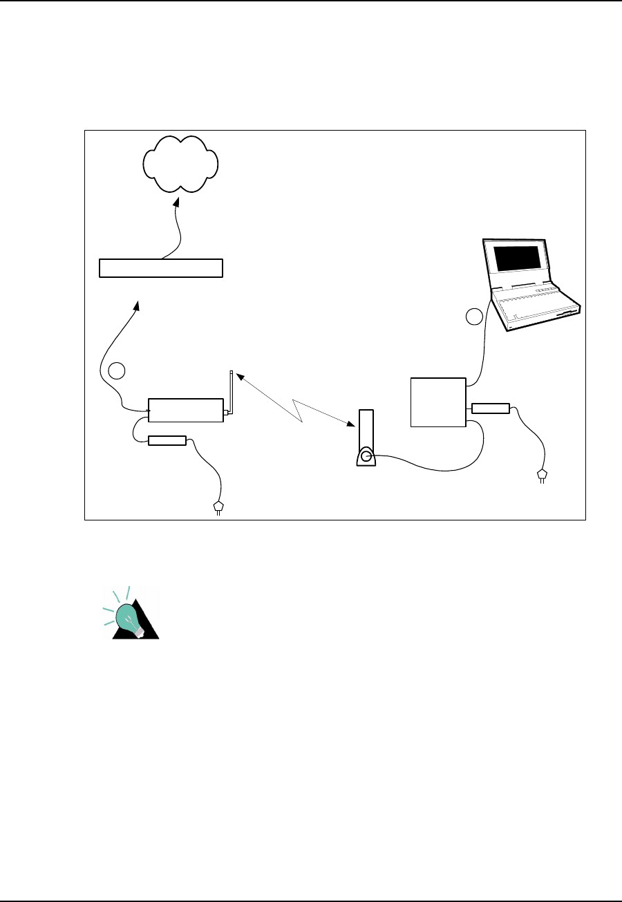
2Quick Startup
This section outlines the procedure for setting up a very simple LMS4000 900 MHz radio
network consisting of one CCU and one EUM. This simple network, which can be set up in a
lab environment, helps you become familiar with basic LMS4000 configuration and operation.
As you become more confident and are ready to progress to customer installations,
WaveRider recommends you read the other sections in the manual.
Quick Startup uses static IP addresses for the purpose of simplicity, even though the CCU and
EUM support DHCP relay.
2.1 Equipment
As a minimum, the Quick Startup requires the following equipment:
one CCU kit, consisting of
• CCU
• CCU power supply and cable
• CCU setup antenna
one EUM kit, consisting of
•EUM
• EUM power supply and cable
• 3m CAT5 crossover Ethernet cable
one PC, equipped with terminal emulation software such as HyperTerminal and an
Ethernet network interface card
one WaveRider indoor antenna, complete with mounting bracket and RF cable
one Straight-through RS-232 serial cable, DB-9 male to DB-9 female
2 Quick Startup
6APCD-LM043-4.0
2.2 Equipment Setup
1. Remove the equipment from the boxes and set up the physical configuration shown in
Figure 1. Use this setup procedure to configure the CCU, while keeping the following
points in mind:
• Maintain the order of installation shown in Figure 1.
• Maintain at least 3 to 5 meters of physical separation between CCUs and
EUMs.
• Ensure the paths between the CCU and EUMs are relatively free from
obstruction.
Figure 1 Quick Startup — CCU Configuration
CAUTION: Always make sure that you connect the antenna to
the CCU or EUM before you apply power to the unit.
2. Configure your PC terminal emulation software as shown in Table 1.
Table 1 Console Settings
Bits per second 9600
Data bits 8
Parity None
Stop bits 1
Flow Control None
CCU3000
RS232 cable
CCU set-up
antenna
CCU power
supply
EUM3000
EUM Antenna
EUM Power Supply
1
3-5metres
2
3
4
5
6
7
Radio
Link

2QuickStartup
APCD-LM043-4.0 7
2.3 CCU Configuration
1. Start the PC terminal emulation software. You will receive the following prompt:
WaveRider Communications, Inc. LMS3000
Password:
The default password is a carriage return.
Console>
The default prompt on your CCU is the CCU Ethernet MAC address.
2. Type the following commands to configure the CCU:
Console> ip ethernet 192.168.10.10 24
Console> ip radio 10.0.0.1 22
Console> ip gateway 192.168.10.1
Console> radio frequency 9150
Console>
Console> save
Basic Config saved
Port Filter Config saved
sntp cfg file saved
Route Config saved
Authorization Database saved
DHCP Server Config saved
3. Reboot the CCU for the changes to take effect.
Console> reset
rebooting CCU ...
(... Power On Self Test ...)
WaveRider Communications, Inc. LMS3000
Password:
TIP: If you want to connect the Quick Setup to the Internet as
outlined in Connecting the Quick Startup to the Internet on page
11, obtain the CCU gateway IP address from your network
administrator. You can then set the CCU Ethernet IP address to
any IP address in the subnet.
4. Confirm the CCU has been properly configured, as follows:
Console> ip
Ethernet IP Address: 192.168.10.10
Ethernet Net Mask : ffffff00
Gateway IP Address: 192.168.10.1
Radio IP Address: 10.0.0.1
Radio Net Mask : fffffc00
Console> radio
RF Power: HIGH
Radio Frequency: 9150
Console>
2 Quick Startup
8APCD-LM043-4.0
2.4 EUM Configuration
1. Connect the PC to the console port of the EUM, as shown in Figure 2.
Figure 2 Quick Startup — EUM Configuration
2. Start the terminal emulation software.
3. Type the following commands to configure the EUM:
WaveRider Communications, Inc. LMS3000
Password:
Console> ip ethernet 10.0.0.2 22
Console> ip gateway 10.0.0.1
Console>
Console> radio frequency 9150
Console>
Console> save
Basic Config saved
Port Filter Config saved
sntp cfg file saved
Console>
4. Reboot the EUM for the settings to take effect.
Console> reset
rebooting EUM ...
(... Power On Self Test ...)
WaveRider Communications, Inc. LMS3000
Password:
CCU3000
RS232 cable
CCU set-up
antenna
CCU power
supply
EUM3000
EUM Antenna
EUM Power Supply
1
Radio
Link
2QuickStartup
APCD-LM043-4.0 9
5. Confirm that the EUM has been properly configured, as follows:
Console> ip
Ethernet/USB IP Address: 10.0.0.2
Ethernet/USB Net Mask : fffffc00
Gateway IP Address: 10.0.0.1
Console> radio
RF Power: HIGH
Radio Frequency: 9150
Console>
2.5 Testing CCU–EUM Communications
Once you have completed the configuration of the Quick Startup, you can test
communications between the CCU and the EUM by pinging the CCU through the EUM
console port.
To Run a Ping Test Through the EUM Console Port
1. Connect the PC to the EUM console port, as shown in Figure 3.
Figure 3 Quick Startup — Ping Test (from console port)
2. From the EUM, ping the CCU radio port (IP address 10.0.0.1), as follows. Press any
key to stop.
console>
console> ping 10.0.0.1
Press any key to stop
PING 10.0.0.1: 56 data bytes
64 bytes from 10.0.0.1: icmp_seq=1. time=112. ms
64 bytes from 10.0.0.1: icmp_seq=2. time=48. ms
64 bytes from 10.0.0.1: icmp_seq=3. time=48. ms
64 bytes from 10.0.0.1: icmp_seq=4. time=32. ms
64 bytes from 10.0.0.1: icmp_seq=5. time=32. ms
CCU3000
CCU set-up
antenna
CCU power
supply
EUM3000
EUM Antenna
EUM Power Supply
Radio
Link
1RS232 cable
2 Quick Startup
10 APCD-LM043-4.0
64 bytes from 10.0.0.1: icmp_seq=6. time=16. ms
64 bytes from 10.0.0.1: icmp_seq=7. time=64. ms
64 bytes from 10.0.0.1: icmp_seq=8. time=64. ms
----10.0.0.1 PING Statistics----
8 packets transmitted, 8 packets received, 0% packet loss
round-trip (ms) min/avg/max = 16/52/112
console>
This test verifies the radio link between the EUM and the CCU.
To Run a Ping Test Through the EUM Ethernet Port
1. Connect the PC to the EUM Ethernet port, as shown in Figure 4.
Figure 4 Quick Startup — Ping Test (from EUM Ethernet port)
2. Open the TCP/IP Properties window in the PC. If you are not sure how, consult your
operating system manual.
3. Select Use the following IP address (or Specify an IP address—the exact wording
depends on your operating system). Enter the following:
• IP Address 10.0.1.2
• Subnet Mask 255.255.252.0
• Default Gateway10.0.0.1
4. From the PC, progressively ping the PC Ethernet port (10.0.1.2), the EUM (10.0.0.2),
and the CCU radio (10.0.0.1) and Ethernet (192.168.10.10) ports.
CCU3000
Ethernet crossover
cable
CCU set-up
antenna
CCU power
supply
EUM3000
EUM Antenna
EUM Power Supply
1
Radio
Link
2QuickStartup
APCD-LM043-4.0 11
2.6 Connecting the Quick Startup to the Internet
Once you have verified that the CCU and EUM are communicating properly, you may want to
to connect the Quick Startup system to the Internet.
To Connect to the Internet
1. Connect the PC to the Ethernet port of the EUM as shown in Figure 5.
Figure 5 Quick Startup — Connecting to the Internet
TIP: If you want to connect the Quick Setup to the Internet, you
must obtain the CCU gateway IP address from your network
administrator. The CCU Ethernet IP address can then be set to
any IP address in the subnet.
2. If you have not already configured the PC IP address as outlined in Testing CCU–
EUM Communications on page 9, open the TCP/IP Properties window in the PC. If
you are not sure how, consult your operating system manual.
3. Select Use the following IP address (or Specify an IP address; the exact wording
depends on the operating system), and enter the following:
• IP Address 10.0.1.2
• Subnet Mask 255.255.252.0
• Default Gateway10.0.0.1
CCU3000
Ethernet crossover
cable
CCU set-up
antenna
CCU power
supply
EUM3000
EUM Antenna
EUM Power Supply
Gateway Router
Internet
1
2Radio
Link

2 Quick Startup
12 APCD-LM043-4.0
4. Select Use the following DNS server address (the exact wording depends on your
operating system), and enter the IP address for the Preferred DNS Server, which is
available from your Network Administrator.
5. Connect the CCU Ethernet port to the appropriate network switch or hub, or directly to
the gateway router of your network.
6. From the PC, you should now be able to open your browser and surf the Web.
2.7 Adding more EUMs to the Quick Startup
You can add other EUMs and PCs to the Quick Startup system. At all times, try to maintain at
least 3 to 5 m (10 to 15 ft.) separation between the EUMs, and between the EUMs and the
CCU.
Other EUMs are added in the same way as the first EUM, using the same gateway IP address
(10.0.0.1), subnet masks (255.255.252.0), and the following EUM and PC IP addresses:
Table 2 Quick Startup — EUM Addresses
EUM
Number EUM IP Address PC IP Address
2 10.0.0.3 10.0.1.3
3 10.0.0.4 10.0.1.4
4 10.0.0.5 10.0.1.5
5 10.0.0.6 10.0.1.6
6 10.0.0.7 10.0.1.7

APCD-LM043-4.0 13
3Detailed Description
This section describes the technologies and features used in the LMS4000 900 MHz Radio
Network.
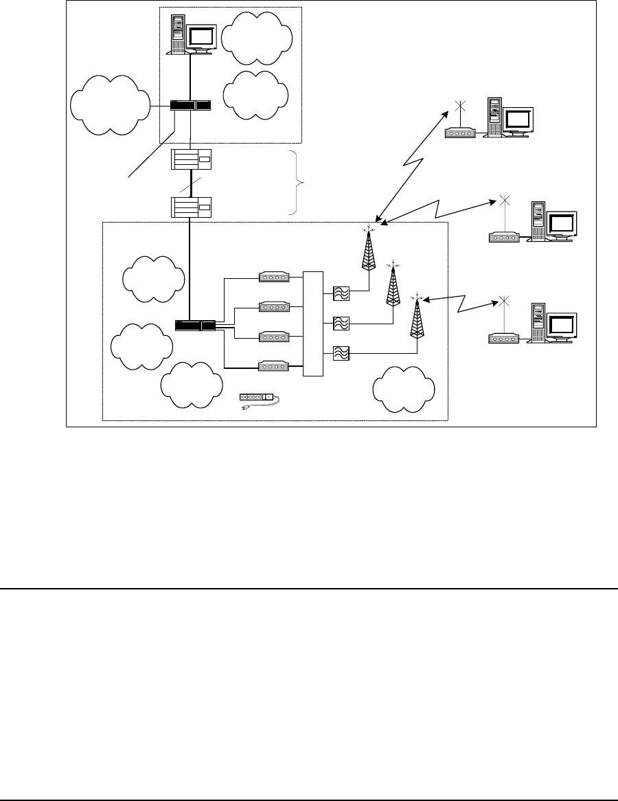
3.1 LMS4000 Overview
Figure 6 is a high-level schematic of the LMS4000 system, showing the key system
components and interfaces.
As shown, each LMS4000 component is associated with one of three major system entities:
• End-user Modem (EUM)
• Communications Access Point (CAP)
• Network Access Point (NAP)
End-user Modem or Customer-premises Equipment
The EUM equipment is installed at the end-user’s premises. It provides an interface to the
customer’s computer or local area network on one side and wireless access to the LMS4000
network on the other.
Communications Access Point (CAP)
The CAP is the collection and distribution point for data travelling to and from the EUMs. In the
EUM-to-network direction, the CAP aggregates the data from the radio channels into a single
data stream, which is passed either directly or over a backhaul facility to the Network Access
Point.
In the Internet-to-EUM direction, the CAP receives data from the Network Access Point and
distributes this data to the appropriate radio channels for transmission to the EUMs over the
900 MHz radio link.
3 Detailed Description
14 APCD-LM043-4.0
Network Access Point (NAP)
The NAP provides the Internet connection point for one or more CAPs. An LMS4000 system
can have more than one NAP. The number of NAPs depends on the geographical layout of
the LMS4000 system and the location of available Internet access points. A single NAP can
provide Internet connection for one CAP, or several CAPs, each either colocated with the NAP
or connected to the NAP over backhaul facilities.
Figure 6 LMS4000 System
The following sections discuss the operation of the LMS4000 900 MHz Radio Network, of
which the CCU and EUM are the key components.
3.2 Communications Access Point
3.2.1 Key Components
The following are key components of the Communication Access Point:
• CCU
•Cavityfilters
• Lightning arrestors
NMS Station
Router
Internet
EUM
Backhaul (NCL1170,
for example)
To Other
CAPs
Network and
Equipment
Management
10/100BaseT
-Subscriber
Management
-Billing Data
- Authorization
- Registration
Layer 3
-Switching
- Routing
NAP
CAP
Routing to/from
Internet
EUM
- Authorization
- Registration
UPS
Radio Control
- Configuration
- Redundancy
CCU
CCU
Back-up CCU
CCU
Antenna
Antenna
Antenna
Cavity Filters
RFSM
Not part of
LMS4000
Switch
10BaseT
End-user PC
EUM End-user PC
EUM End-user PC
3 Detailed Description
APCD-LM043-4.0 15
• Transmission line
• Antenna
• Ethernet switch
Each of the above components is discussed in the following sections.
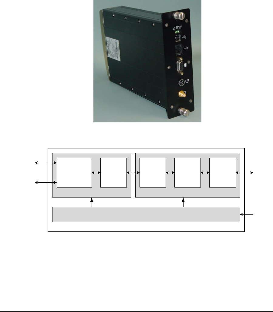
CCU
The CCU, shown in Figure 7, is the wireless access point for up to 300 end-user modems. The
functional blocks of the CCU are illustrated in Figure 8.
Figure 7 CCU
Figure 8 CCU Functional Blocks
Baseband
Controller
Radio
Baseband
Processor
Power
Amplifier/
Low-noise
Amplifier
Up/Down
Converter
Media
Access
Controller
Ethernet Port
10 BaseT
Console Port
DB9, RS232
CCU3000
Antenna
7.5 VDC
Radio
Power
Baseband
3 Detailed Description
16 APCD-LM043-4.0
The CCU routes IP packets received from the CCU radio port
• to internal CCU processes,
• through the CCU Ethernet port to any router on the Ethernet network, such as the
Network Access Point, or
• back out the radio port to other EUMs (EUM-to-EUM packets).
The CCU routes IP packets that are received from the Network Access Point through the
Ethernet port
• to internal CCU processes, or
• through the radio port to the destination EUM.
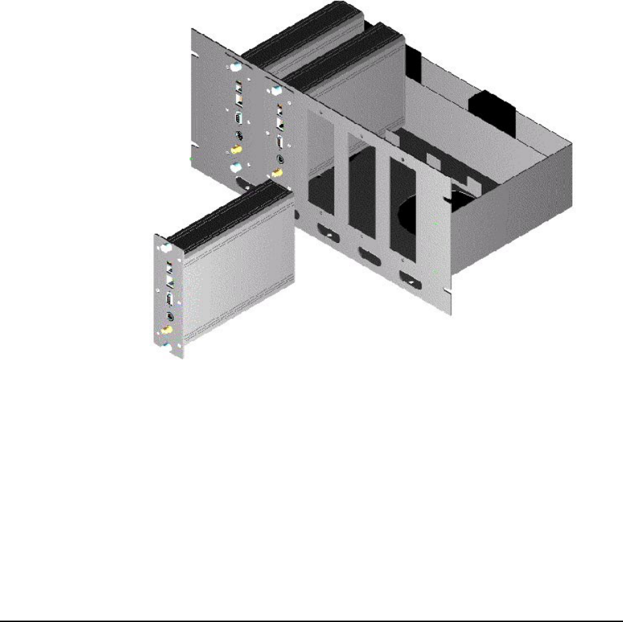
The CCU can be installed in a standalone configuration, or in a CCU shelf, as shown in Figure
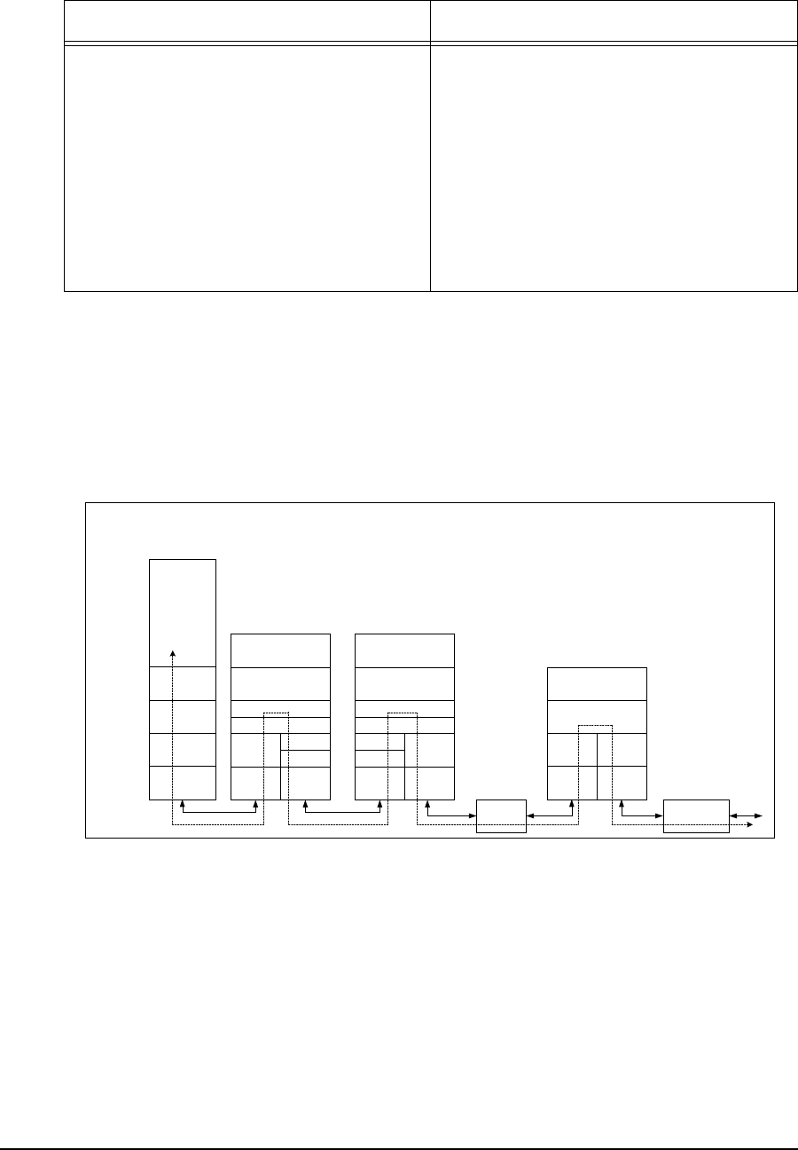
9, with other operating and backup CCUs. The CCU is powered by an AC/DC power supply,
which can also stand alone or be installed in the CCU shelf. The CCU operates independently
of other CCUs and can be swapped out without interrupting the operation of other CCUs.
Figure 9 CCU Shelf
Up to four CCUs can be installed at the same CAP, as follows:
• Up to three operating CCUs, each with its own cavity filter, lightning protector,
transmission line, and antenna.
• One backup CCU, if CCU redundancy is provisioned. Since the backup CCU is
“switched” into the RF circuit of the failed CCU, by the RFSM, it does not require its
own cavity filter, lightning protector, transmission line or antenna.
The CCU comes with a setup antenna, which can be used during CCU configuration and test,
prior to deployment.

3 Detailed Description
APCD-LM043-4.0 17
Cavity Filters
WaveRider recommends the use of cavity filters with all CCUs and is mandatory if colocated
with other CCUs. Cavity filters help to isolate the CCU from inband interferers, such as
colocated CCUs or non-WaveRider ISM band equipment, as well as out-of-band interferers,
such as cellular base stations and paging transmitters.
Lightning Arrestors
Since the CCU antenna is mounted outdoors, lightning arrestors are required with all CCU
installations. Lightning arrestors divert most of the energy from a lightning strike away from the
RF transmission line and equipment, to a bonded ground point. The lightning arrestor is
installed in series with the RF transmission line, as close as possible to the point where the
transmission line enters the building.
Transmission Line
A good quality RF transmission line should always be used to connect the CCU to the
antenna. “Good quality RF transmission line” means one that is weather resistant and UV-
protected, and that has low attenuation characteristics. All connectors in the transmission line
should be wrapped to prevent water penetration. Connecting the CCU to the transmission line
requires RF jumper cables, available from WaveRider.
Antenna
Each active CCU requires its own antenna. Antennas can be omnidirectional or have a
sectored beam pattern (for example, 180, 120, or 90 degrees). The choice of antenna is be
based on site and RF engineering considerations, and FCC and Industry Canada guidelines,
which are summarized in Appendix D on page 185.
Ethernet Switch
An Ethernet switch is required at the CAP if it is provisioned with more than one CCU, or to
interface with certain types of backhaul equipment.
3.2.2 Optional Components
The following Communications Access Point components are optional:
•RFSM
• RF Distribution Panel
RFSM
The optional RFSM (RF Switch Matrix), shown in Figure 10, is required if CCU redundancy is
provisioned. The RFSM monitors the health of the operating CCUs. If a CCU fails, the RFSM
switches to a provisioned backup CCU, which is automatically programmed with the same
3 Detailed Description
18 APCD-LM043-4.0
settings as the failed CCU. In this way, the CAP can be provisioned for N+1 redundancy,
meaning there is one backup CCU for ‘N’ operating CCUs, up to a maximum of N=3.
Figure 10 RFSM
RF Distribution Panel
The optional RF Distribution Panel provides
• external interface to the antenna subsystem and site ground,
• common surge protector mounting point for each external RF interface, and
• common ground point for all CAP components.
Other Optional CAP Equipment
Depending on your configuration and operational requirements, you may require other
components in your LMS4000 CAP, such as a UPS system, CCU Shelf, or free-standing
19–inch rack.
The CCU Shelf is a standard 19-inch mounting rack with an integrated power supply fan and
cooling fans. It contains five CCU slots, for up to three operating CCUs, a backup CCU, and
backhaul CCU.
These optional components can be ordered through WaveRider.
3.3 Customer-premises Equipment
3.3.1 Key Components
The following Customer-premises Equipment components are key:
•EUM
• EUM antenna
• Transmission line
• Lightning arrestor
3 Detailed Description
APCD-LM043-4.0 19
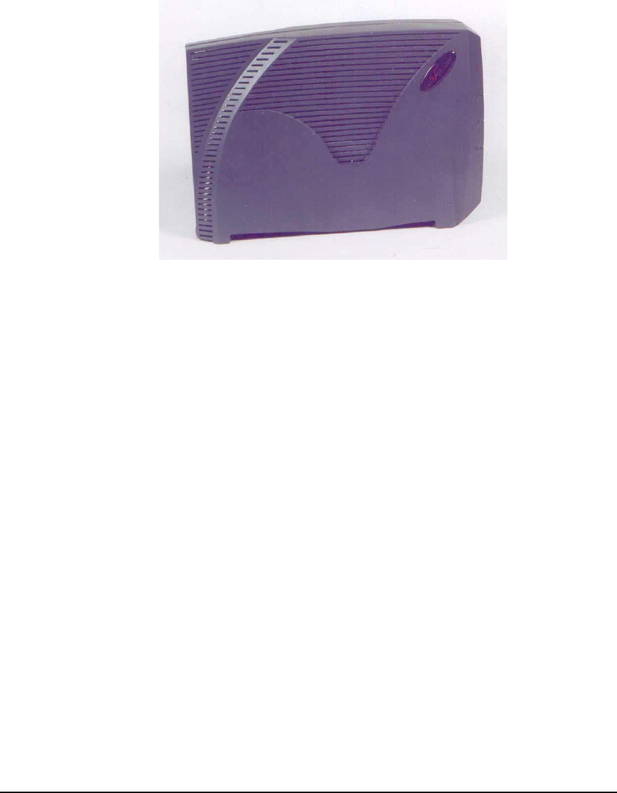
3.3.2 EUM
The EUM, shown in Figure 11, is a wireless modem that connects to the end-user’s computer
through an Ethernet connection. The EUM, which acts as a network bridge, receives data from
the CCU over the 900 MHz radio link, and then forwards this data to EUM internal processes
or to the end-user’s computer through the Ethernet port. In the other direction, the EUM
forwards data received from the end-user’s computer over the radio link to the CCU.
Figure 11 EUM
The EUM functional blocks are the same as those of the CCU and are illustrated in Figure 8.
3 Detailed Description
20 APCD-LM043-4.0
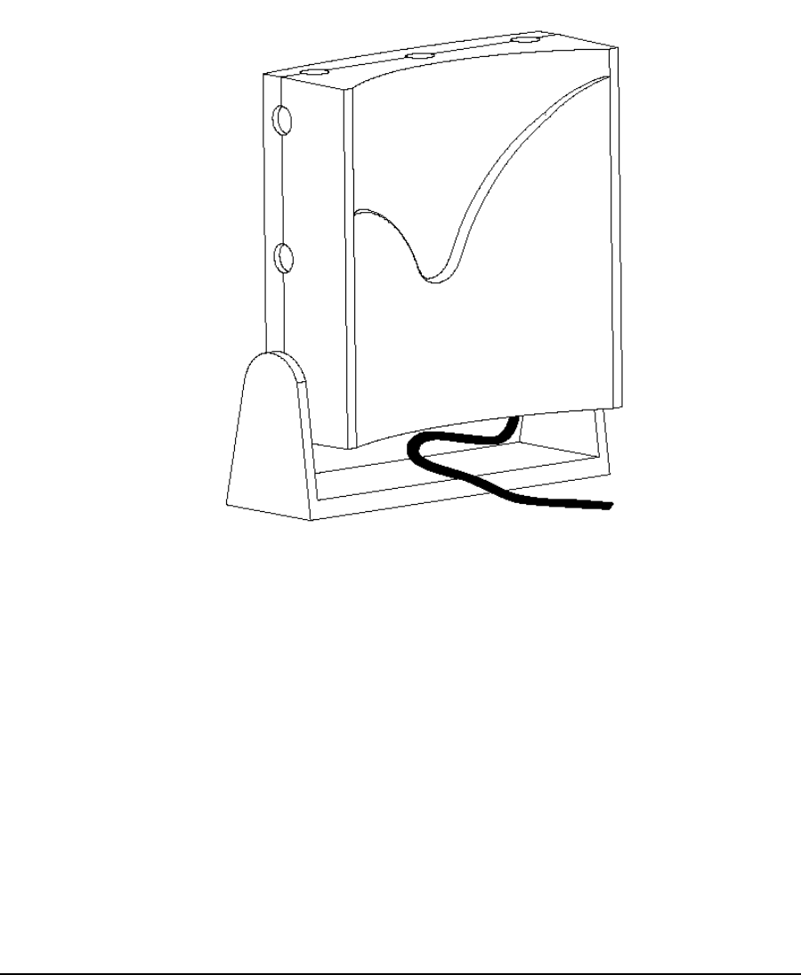
EUM Antenna
For many EUM installations, you can use an indoor antenna. WaveRider recommends the
WaveRider directional antenna with switched-beam diversity. This antenna, shown in Figure
12, performs very well in cases where the radio path to the CCU is obstructed and/or where
there is significant multipath. The diversity antenna accepts a DC signal on the antenna cable
from the EUM, for beam pattern selection. The antenna comes with a mounting bracket and is
designed to mount vertically on walls or windows (using drywall screws for wall mounting or
suction cups for window mounting), or horizontally (on desks, for example, using the suction
cups).
Figure 12 WaveRider Indoor Directional Antenna with Switched-beam Diversity

3 Detailed Description
APCD-LM043-4.0 21
The WaveRider diversity antenna contains two vertical antenna elements mounted inside and
on either side of the antenna housing. The phasing between these elements, which modifies
the antenna pattern, is controlled by a DC voltage from the EUM. It produces two patterns, one
perpendicular to the face of the antenna, which has a gain of about 6 dBi, and the other, a
dual-beam pattern off both sides, offering about 3 dBi gain for each beam. These beam
patterns are illustrated in Figure 13.
Figure 13 WaveRider Switched-beam Diversity Antenna — Beam Patterns
The EUM samples the signal strength from both antenna patterns during the preamble of
every received packet and automatically selects the best signal. When the EUM transmits, it
sends on the antenna pattern that was last used to receive a signal. Since most of the traffic
comes from the CCU, the EUM samples the signal strength often—typically faster than once
every 5 ms.
The end user must position the switched-beam diversity antenna correctly to receive an
adequate signal level. The Radio LED on the EUM, described in Indicators and Connectors on
page 74, can be used to help with the alignment. Since the switched-beam diversity antenna
has a good front-to-back ratio, it can be positioned to suppress interference from other
wireless devices at the end-user’s premises.
WaveRideralsooffersasimpledipoleantenna,whichcanoftenbeusedwherethepathtothe
CCU is very short or relatively unobstructed; i.e., where there is a short line of sight path from
the EUM to the CCU with no more than a wall or window obstructing the path.
Other WaveRider-approved antennas can be used at EUM locations that require outdoor
antennas. A professional installer is required to install outdoor EUM antennas to ensure the
antenna system is properly installed with lightning protection and consistent with FCC and
Industry Canada guidelines, which are outlined in Appendix D on page 185.
Transmission Line
If the WaveRider diversity or dipole antenna is used, it comes equipped with RF cables and
connectors. The connector is a proprietary WaveRider connector, which is mandated by the
FCC requirement that the connectors used in ISM band products that are not professionally
installed must be unique, or at least not readily available. If an alternate indoor or outdoor
antenna is used, the installer must obtain an RF jumper cable to connect the antenna cable to
the EUM. These jumper cables can be obtained from WaveRider.
Beam Pattern A Beam Pattern B
3 Detailed Description
22 APCD-LM043-4.0
Lightning Arrestor
A lightning arrestor is required at the EUM only if an outdoor antenna is used.
3.4 Basic Operation
3.4.1 LMS4000 Transmission Concept
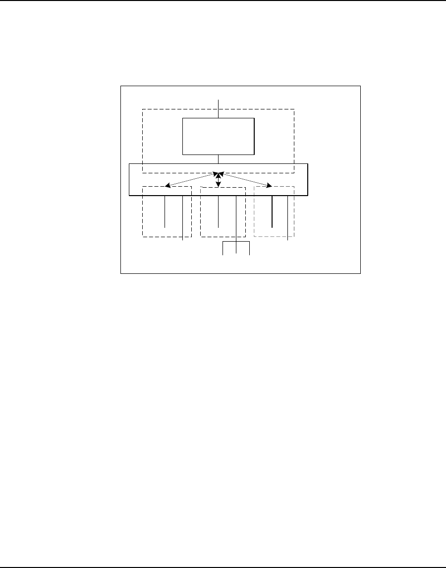
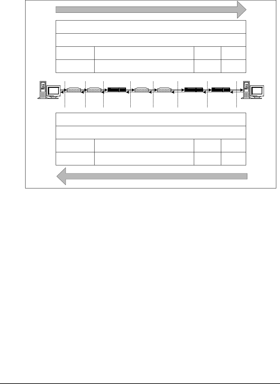
Conceptually, the LMS4000 900 MHz Radio Network can be thought of as an Ethernet switch
with a built-in router, as shown in Figure 14.
Figure 14 LMS4000 Transmission Concept
In the above diagram, the “switch” consists of the CCU and EUM physical, MAC, and IP
bridging layers, and the 900 MHz link between them. IP packets originating from any host in
the radio subnet (EUM or PC, for example), which are destined for a host that is also in the
radio subnet, are “switched” by the CCU directly to that host. IP packets originating from any
host in the radio subnet, which are destined for a host outside the radio subnet, are “switched”
to the CCU router for routing to the destination host.
IP packets coming into the CCU Ethernet port, which are destined to a host in the radio
subnet, are routed to the “switch” and “switched” to the host.
3.4.2 CCU and EUM Configuration
When CCUs and EUMs are shipped from the factory, they are pre-programmed with a set of
factory default settings. Some of these default settings must be modified before the system
can pass traffic. These basic settings are listed Table 3 and Table 4. Once your system is
carrying traffic, you can configure the more advanced CCU and EUM features and functions,
which are also listed in these tables.
EUM Host
PC
EUM Host
End-user
LAN
PC
EUM Host
CCU Router
Application
CCU Ethernet port
"Switch"
CCU

3 Detailed Description
APCD-LM043-4.0 23
Table 3 CCU Configuration
Table 4 EUM Configuration
Basic CCU Settings Advanced CCU Settings
Before the system can pass traffic, input or
modify the following CCU parameters:
• CCU Ethernet IP address
• CCU radio IP address
• Gateway router IP address
• Radio frequency
For instructions on how to set these
parameters, read the following sections:
•Quick Startup on page 5
•IP Network Planning on page 53
•Radio Network Planning on page 59
Once the system is passing traffic, you can
start to configure and fine tune the following
CCU features and functions:
• Grade of Service
• DHCP relay
•Portfiltering
• SNTP time clock
• SNMP communities
You can find a technical description of these
features in CCU–EUM Interface — Detailed
Technical Description on page 28. You can
find procedures for configuring these
features in Configuring the CCU on page
83.
Basic EUM Settings Advanced EUM Settings
Before the system can is implemented, input
or modify the following EUM parameters:
• EUM Ethernet IP address
• Gateway (CCU Radio) IP address
• Radio frequency
For instructions on how to set these
parameters, read the following section:
•Configuring the EUM on page 97
Note: Since the EUM is a wireless bridge, it
passes data without having a unit or
gateway IP address assigned. However, to
support system management (SNMP, for
example) of an EUM, a unique IP address
must be assigned. The EUMs all ship with
the same default unit and gateway IP
addresses, so if these are not changed you
will experience network IP conflicts.
Once the system is passing traffic, you can
start to configure and fine tune the following
EUM features and functions:
•Portfiltering
• SNMP communities
•Customerlist
For instructions on how to set these
parameters, read the following section:
•Configuring the EUM on page 97
3 Detailed Description
24 APCD-LM043-4.0
Table 5 End-user PC Configuration
3.4.3 LMS4000 Protocol Stacks
The LMS4000 900 MHz Radio Network is an IP (layer 3) network that provides connectivity
from the end-user’s computer to the Internet.
Figure 15 shows the protocol stacks through which an IP packet traverses as it travels
between the end-user’s computer, shown on the left, and the Internet, shown on the right.
Figure 15 LMS4000 Protocol Stacks
3.4.4 Basic Data Transmission
This section describes how an EUM registers, and once it is registered, how data traffic flows
from the Internet to the end-user PC and from the end-user PC to the Internet. The process in
both directions involves CCU and EUM data tables, which are described in more detail in
Appendix E on page 183.
Basic End-user PC Settings Advanced End-user PC Settings
In addition to the above CCU and EUM
settings, the end-user’s PC must be
assigned an IP address and subnet, and a
static gateway address. These IP addresses
can be statically assigned to the PC, as
described in Configuring EUM IP
Parameters on page 99, or dynamically
assigned from a DHCP server by
configuring the CCU for DHCP Relay,
described in DHCP Relay on page 48, and
Configuring DHCP Relay on page 88.
DHCP
10BaseT
Ethernet MAC
IP
TCP/UDP
Applications
(email,
browser, ftp,
telnet, ICQ,
VoIP, ...)
1
2
3
4
5-7
OSI
Layer End-User's
Computer
10BaseT
Ethernet
MAC
IP Port Filtering
EUM3000
PMAC
DSSS
Radio 10BaseT
Ethernet
MAC
IP Port Filtering
CCU3000
DSSS
Radio
Backhaul
10BaseT
Ethernet
MAC
IP Routing
NAP Router
10BaseT
Ethernet
MAC
Internet
Connection
TCP/UDP
Auth/Reg
PMAC
Auth/Reg
IP Bridging IP Routing
TCP/UDP TCP/UDP
EUM Application CCU Application

3 Detailed Description
APCD-LM043-4.0 25
EUM Registration
EUMs need to register with the CCU before user traffic can pass between the LMS4000 900
MHz Radio Network and the end user. The heart of EUM registration is the Authorization
Table, discussed in Authorization Table (CCU only) on page 189.
The EUM registration process is as follows:
1. The system operator enters the EUM’s grade of service in the CCU Authorization
Table, described in Authorization Table (CCU only) on page 189.
2. On power up, the EUM sends a registration_request to the CCU.
3. The CCU obtains the EUM’s grade of service from the Authorization Table. If the EUM
grade of service is DENIED, the CCU sends a de-registration_response to the EUM
and data communications are enabled. The EUM continues to send
registration_requests to the CCU approximately every 10 minutes.
4. If the EUM grade of service is not DENIED, the CCU sends a registration_response to
the EUM, and data communications are enabled. At this point, the CCU adds the EUM
to the Registration Table, described in Registration Table (CCU only) on page 190.
5. If at some later time, the EUM does not respond to messages from the CCU, the CCU
sends a de-registration_request to the EUM and removes the EUM from the
Registration Table. If there has been no traffic to or from the EUM for more than 12
hours, the CCU removes the EUM from the Registration Table without sending it a de-
registration_request.
3 Detailed Description
26 APCD-LM043-4.0
Addressing of IP Packets
Figure 16 shows how the source and destination MAC and IP addresses are sent in IP
packets travelling between the end-user’s PC and the Internet network servers.
Figure 16 Addressing of IP Packets
As shown in Figure 16, if NAT is not enabled in the NAP Router, then the source and
destination IP addresses are maintained throughout the route between the end-user PC and
network servers. The source and destination MAC addresses, however, change whenever the
packet is passed through a router. This change of MAC addresses also takes place in the
CCU router application.
Internet to End-user Computer Data Transmission
1. Internet traffic comes through the gateway router, and possibly through backhaul and
Ethernet switches, to the CCU Ethernet port.
2. The CCU receives an IP packet through the CCU Ethernet port and checks the TCP
or UDP port number. If the port number appears in the CCU Port Filter Table,
described in Port Filter Table (CCU and EUM) on page 183, the packet is discarded.
3. The CCU reads the destination IP address. If the destination IP address is the same
as either the CCU Radio or Ethernet IP address, the packet is sent to the CCU
application.
4. The CCU checks the Routing Table, described in Routing Table (CCU and EUM) on
page 184. If the route to the destination is through the CCU Ethernet port, then the
packet is discarded, since it is not destined for a host in the CCU’s radio subnet.
Network Server
NAP Router
(no NAT)
EUM CCU BackhaulSwitch
End-user PC
Internet Router
(several)
Network Server IP Address
End-user PC IP Address
End-user PC MAC
Address
CCU Radio MAC
Address
Destination IP
Address
Source IP
Address
Destination
MAC Address
Source MAC
Address
AABB
Destination IP
Address
Source IP
Address
Destination
MAC Address
Source MAC
Address
Destination IP
Address
Source IP
Address
Destination
MAC Address
Source MAC
Address
Destination IP
Address
Source IP
Address
Destination
MAC Address
Source MAC
Address
NAP Router MACAAddress
CCU Ethernet MAC Address
Internet Router
MACAAddress
Network
Server MAC
Address
NAP Router
MACBAddress
Internet
Router MACB
Address
End-user PC IP Address
Network Server IP Address
CCU Radio MAC
Address
End-user PC MAC
Address CCU Ethernet MAC Address
NAP Router MACAAddress
NAP Router
MACBAddress
Internet
Router MACB
Address
Internet Router
MACAAddress
Network
Server MAC
Address
End-user PC to Network Server
Network Server to End-user PC
Backhaul

3 Detailed Description
APCD-LM043-4.0 27
5. If the route to the destination is through the CCU Radio Port, then the CCU obtains the
destination Ethernet MAC address from the ARP Table, described in ARP Table (CCU
and EUM) on page 187. If the destination is not listed in the ARP Table, the CCU
obtains its MAC address by issuing an ARP query. Once it gets the MAC address, it
adds the entry to the ARP Table.
6. Using the destination Ethernet MAC address, the CCU obtains the EUM ID from the
Address Translation Table, described in Address Translation Table (CCU only) on
page 188.
7. Using the EUM ID, the CCU obtains the EUM grade of service from the Registration
Table, described in Registration Table (CCU only) on page 190.
8. The IP packet is then transmitted through the Polling MAC and radio interface to the
EUM.
9. The EUM receives the packet through the EUM radio port and checks the port
number. If the port number appears in the EUM Port Filter Table, the packet is
discarded.
10. If the port number does not appear in the EUM Port Filter Table, the EUM checks the
destination MAC address. If the MAC address is the EUM MAC address, then the
packet is forwarded to the EUM application; otherwise, the IP packet is sent out
through the Ethernet port to the end user’s equipment.
End-user Computer to Internet Data Transmission
1. The EUM receives IP packets from the end-user’s equipment through the Ethernet
port.
2. The EUM checks the port number. If the port is listed in the EUM Port Filter Table, the
packet is discarded.
3. If it is not already in the list, the EUM adds the source Ethernet address to the
Customer Table, described in Customer Table (EUM only) on page 192. The EUM
determines whether or not the source is entitled to air access, based on the Customer
Table.
4. If the source is not entitled to air access, the packet is discarded.
5. The EUM checks the destination MAC address. If the destination MAC address
appears in the Customer Table, meaning the destination is on the Ethernet side, the
packet is discarded.
6. If the destination MAC address is the same as the EUM MAC address, then the
packet is forwarded to the EUM application; otherwise, it is forwarded through the
polling MAC and radio link to the CCU.
7. The CCU receives the packet through the CCU radio port. The CCU either updates or
adds the Ethernet address to the Address Table.
8. The CCU checks the port number. If the port number appears in the CCU Port Filter
Table, the packet is discarded.
9. The CCU checks the destination MAC address. If the destination MAC address is not
in the Address Table, the packet is sent to the CCU router application.
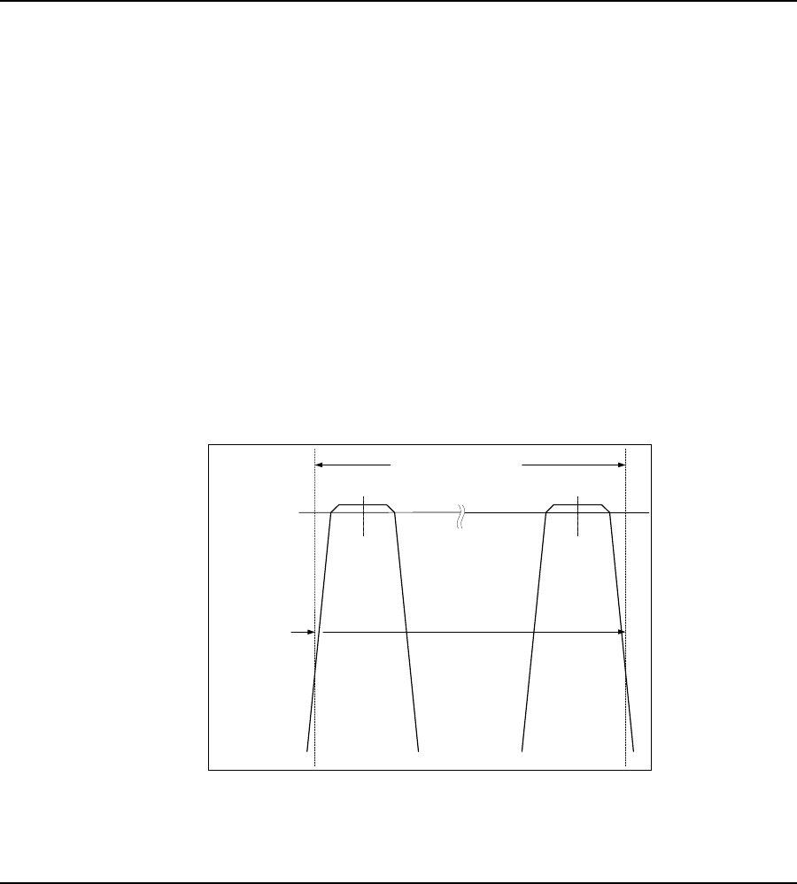
3 Detailed Description
28 APCD-LM043-4.0
10. If the IP address is the same as either the CCU radio or Ethernet IP address, the
packet is forwarded to the CCU application; otherwise, the CCU gets the appropriate
gateway IP address from the Routing Table and the gateway MAC address from the
ARP Table, and then sends the packet to the gateway (most likely the NAP router)
through the Ethernet port.
NOTE: The CCU and EUM pass only IP or ARP packets. All other
packets are discarded so non-IP packets, such as IPX/SPX, are
not passed over the radio link.
3.5 CCU–EUM Interface — Detailed Technical Description
This section provides a detailed description of the physical and MAC layers of the interface
between the CCU and EUM, depicted in Figure 15 on page 24.
3.5.1 Physical Layer (DSSS Radio)
Frequency Band
The LMS4000 900 MHz Radio Network operates in the 902-928 MHz Industry, Scientific, and
Medical (ISM) frequency band.
Channel Bandwidth
The channel bandwidth is 6 MHz. This channel bandwidth is used to determine the lowest and
highest allowable channel in the band. As illustrated in Figure 17, the center frequency of the
lowest and highest channels have to be set such that the signal power that falls in the bands
adjacent to the ISM band does not exceed FCC and Industry Canada limits.
Figure 17 Determination of Lowest and Highest Channel
902 - 928 MHz ISM Band
FCC limit for
emissions in
adjacent band
Lowest
Channel
905 MHz
Highest
Channel
925 MHz

3 Detailed Description
APCD-LM043-4.0 29
The channel bandwidth also determines the minimum adjacent channel spacing for colocated
CCUs.
Channels
There are 101 channels in the band, set in 0.2 MHz increments:
Table 6 LMS4000 900MHz Radio Network Channelization
Modulation
The CCU-EUM radio channel is based on DSSS (Direct-Sequence Spread Spectrum) signals,
modulated with CCK and Barker-coded BPSK and QPSK, similar to that defined in IEEE
802.11 for the 2.4 GHz ISM band.
DSSS offers the following advantages:
•Reduced power spectral density: Spreading over a wider bandwidth reduces the
spectral density (power per Hz of bandwidth) of the transmitted signal, allowing
simultaneous operation of many spread-spectrum systems in the same frequency
band and geographic area. The reduced spectral density also allows you to meet the
regulatory emissions requirements in the ISM frequency bands.
•Transmission security: It is technologically more difficult to recover (or jam, in the
case of military communications systems) spread-spectrum signals than it is to
recover conventional narrowband signals.
Channel Center Frequency
Lowest channel 905.0 MHz
... 905.2 MHz
... 905.4 MHz
... ...
... 924.8 MHz
Highest channel 925.0 MHz
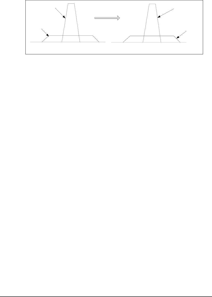
3 Detailed Description
30 APCD-LM043-4.0
•Interference suppression: The same mechanism that de-spreads the desired signal
in the receiver, spreads undesired signals, which then appear to the receiver as lower
levels of RF noise. This effect is illustrated in Figure 18.
Figure 18 Effect of Despreading
Data Rate
The raw channel bit rate is 2.75 Mbps. The maximum data rate presented to the MAC layer is
2.4 Mbps, which translates to a peak FTP rate of about 2 Mbps.
Colocated Channels
A maximum of four orthogonal (nonoverlapping) channels can be provisioned at a single CAP
but WaveRider recommends a maximum of three. To ensure adequate isolation between
channels, a minimum co-channel spacing of 6.6 MHz is recommended, as is the use of
channel filters and a properly engineered antenna system. A possible frequency set for a
three-channel CAP is
• 905.0 MHz
• 915.0 MHz
• 925.0 MHz
A separate CCU, channel filter, transmission line, lightning protector, and antenna are
required for each of the orthogonal channels.
Duplexing
The radio channel uses Time Division Duplexing (TDD), which means that the CCU or EUM is
in either receive or transmit mode, but does not transmit and receive at the same time.
Transmit Power
The maximum transmit power (HIGH power setting) of the CCU and EUM is +26 dBm,
measured at the unit’s RF connector. It does not include gains and losses from antennas,
transmission lines, and lightning arrestors, all of which affect the ERP (Effective Radiated
Power) from the CAP or customer’s premise. Refer to Appendix D on page 185 for a
discussion of related FCC and Industry Canada guidelines.
Before De-spreading
Interferer
Desired
Signal
After De-spreading
Desired Signal
Inteferer
Becomes

3 Detailed Description
APCD-LM043-4.0 31
The CCU and EUM transmit power can each be set to +15 dBm (LOW power setting) to
address special or regional applications of the LMS4000,or for bench testing.
Receive Sensitivity
The receive sensitivity (received signal required to attain a raw data BER of 10-5 or better
using 1000-byte packets) of the CCU and EUM is < -86 dBm, measured at the unit’s RF
connector.
Antenna Connector
The RF connector used on the CCU and EUM is a WaveRider-proprietary connector. As noted
above, the use of a proprietary antenna connector is mandated by FCC requirements for a
unique RF connector on ISM products.
Antenna Control (EUM)
A DC voltage (5 VDC or 7.5 VDC) is applied to the EUM RF connector for powering and
controlling the WaveRider diversity antenna. One beam pattern is selected if the voltage is 5
VDC. A second beam pattern is selected if the voltage is 7.5 VDC.
CAUTION: The EUM sends DC power and control voltages
through the RF connector to the switched-beam diversity
antenna. You must use WaveRider-approved indoor or outdoor
antennas; otherwise, you could inadvertently short out the DC
voltage and damage the EUM. Contact WaveRider Technical
Support for a list of approved antennas.
Propagation Path
CCU and EUM radios and antennas provide the basis for excellent radio propagation in both
line of sight (LOS) and non line of sight (NLOS) EUM installations. Radio propagation in the
902 – 928 MHz ISM band is superior to propagation in higher ISM bands for several reasons:
• Lower free space loss
• Lower cable loss
• Lower vegetation loss
• Better wall and glass penetration
• More signal recovery from diffraction
• More signal recovery from reflections
Radio line of sight exists when there is a clear optical path between the CCU and EUM
antennas, as well as adequate clearance of the path over terrain, foliage, and buildings. This
clearance requirement is called the Fresnel clearance. The required clearance varies along
the path and reaches a maximum at the path midpoint. If you have a path with Fresnel
clearance, the loss between the antennas is generally equivalent to free-space loss and can
be readily calculated.

3 Detailed Description
32 APCD-LM043-4.0
NLOS exists when the path between the CCU and EUM is obstructed, or partially obstructed,
by terrain, buildings, or foliage. NLOS is illustrated in Figure 19. Since radio waves reflect,
refract, and diffract, a non line of sight path does not necessarily mean the EUM-CCU radio
link does not have enough signal margin. It simply means that the path loss is be greater than
the LOS path loss. Within the engineered NLOS coverage range of the CCU, the NLOS path,
using an indoor antenna, is acceptable for most EUM installations.
Figure 19 Typical NLOS Path
It is difficult to accurately predict NLOS path loss; however, a lot of field data has been
collected and factored into commercially available path-prediction software.
LMS4000 900 MHz radio coverage prediction depends on the following:
• CCU radio output power, transmission-line losses, and antenna height and gain
• Length of the path between the CCU and EUM
• Height of terrain, foliage, and buildings along the path between the CCU and EUM,
which determines the percentage of the path that is obstructed.
• EUM antenna height and gain, transmission-line losses, and receiver sensitivity
• If the EUM antenna is installed indoors, location of the EUM antenna within the end-
user premises, and the premises building type and wall construction
The EUM has been designed to work with the WaveRider indoor switched-beam diversity
antenna. Where greater range is required, outdoor EUM antennas are also available.
Generally, the higher the CCU antenna, the better the range, especially for LOS performance.
Ideally, the CCU antenna should be installed well above the average height of trees in the
vicinity of the CCU.
3 Detailed Description
APCD-LM043-4.0 33
To illustrate the impact that proper siting of the CCU has on the LM4000 radio coverage,
consider the three cases shown in Figure 20.
Figure 20 Examples of Radio Paths
• Case 1 is a clear, unobstructed path between the CCU and the EUM, with full Fresnel
clearance.
• Case 2 is a clear, unobstructed path, except for the last few hundred meters, which is
obstructed by foliage and terrain.
• Case 3 is obstructed in the vicinity of the CCU for the first few hundred meters, and
then clear and unobstructed to the EUM.
EUM-1
EUM-2
CCU
EUM-3
Case 1
Unobstructed Path
Case 2
Path Obstructed in
Vicinity of EUM
Case 3
Path Obstructed in
Vicinity of CCU
3 Detailed Description
34 APCD-LM043-4.0
You can predict the amount of path loss for each of these cases, as illustrated in Figure 21.
Figure 21 Path Loss Calculation
As shown in Figure 21, the path loss for each case is quite different:
•Case 1 (Unobstructed Path): Over the length of the path, the signal drops as 1/R2,
where R is the distance from the CCU. The range, Rcase1, is determined by the
distance at which the signal reaches threshold plus the desired fade margin.
•Case 2 (Path Obstructed in Vicinity of EUM): From the CCU, the signal initially
drops as 1/R2until it reaches the obstructions in the vicinity of the EUM. Through
these obstructions, the signal drops more steeply than it does in the unobstructed
case, more like 1/R4. Once again, the range, Rcase2, is determined by the distance at
which the signal reaches threshold plus the desired fade margin. As shown above,
Rcase2 <R
case1, which intuitively makes sense. If the path to the EUM is unobstructed,
you would expect to be able to serve EUMs that are farther from the CCU, and to
provide better fade margin to those that are in closer.
•Case 3 (Path Obstructed in Vicinity of CCU): From the CCU, the signal initially
drops as 1/R4until it leaves the obstructing clutter and terrain in the vicinity of the
CCU. Once the signal leaves these obstructions, it drops as 1/R2since the remainder
of the path is clear. Once again, the range Rcase3, is determined by the distance at
which the signal reaches threshold plus the desired fade margin. As shown above,
Rcase3 <R
case1. Although it shows Rcase3 <R
case2, this may or may not always be the
case; however, it is always true that the margin is greater for Case 2 than Case 3, in
the coverage area indicated by the shading in Figure 21. In this area, the probability of
successful indoor installs is likewise higher for Case 2 than Case 3.
Range
Case 1
Unobstructed Path
Free Space Loss
Case 2
Path Obstructed
in Vicinity of EUM
Case 3
Path Obstructed
in Vicinity of CCU
Tx O/P
Rx Threshold
Fade Margin
Rcase 3 Rcase 2 Rcase 1
Probability of successul indoor installation is
greater for Case 2 than for Case 3, in this
region

3 Detailed Description
APCD-LM043-4.0 35
The following key conclusions that can be drawn from the simple example and analysis shown
above:
• Coverage range and fade margins are maximum when paths are clear and
unobstructed.
• Coverage range and fade margins are reduced for specific EUMs if there is
obstructing clutter and terrain in the vicinity of these specific EUMs.
• Coverage range and fade margins are reduced for all EUMs if there is obstructing
clutter or terrain in the vicinity of the CCU. For this reason, it is critical that the CCU
location be chosen and the antenna height be sufficient to eliminate local obstructions
for all possible radio links from the CCU. By local, it is recommended that the radio
paths be obstruction-free between the CCU and halfway to the limit of the coverage
range.
Table 7 shows the typical radio coverage (distance from the CCU) that the LMS4000 900 MHz
Radio Networks can achieve. Table 7 should be used as a planning guideline only, due to the
difficulty of accurately predicting radio coverage.
Table 7 Typical Radio Coverage
The following assumptions have been made in calculating the above ranges:
• For practical purposes, assume that typically 80% of the subscribers in the predicted
coverage area will be able to receive service. Higher coverage is possible but often
requires more extensive RF engineering.
• LOS (line of sight) means optical view and radio Fresnel clearance between the EUM
premise and the CCU antenna.
• Typical CCU antenna height of 130 ft. (40 m), at least 10 ft. (3 m) above the trees.
• Typical EUM antenna height (for outdoor antennas) of at least 13 ft. (4 m).
• The CCU EIRP has been maximized to +36 dBm in all cases. Refer to Appendix D on
page 181 for further guidelines.
• The EUM outdoor antenna (Yagi antenna, for example) has a gain of 9 dBi, and the
indoor antenna (WaveRider switched-beam diversity antenna) has a gain of 6.6 dBi.
• Coverage with the WaveRider indoor switched-beam diversity antenna depends on
the composition of the exterior walls and structure of the end-user’s premises. For
best results, the EUM antenna should be installed behind a window.
Actual results vary significantly due to local conditions. Coverage-area prediction that takes
into account local terrain and clutter factors provides a better estimate of coverage.
EUM Installation Typical LOS Range Typical NLOS Range
Indoor Antenna
(path to CCU is through a
window) 3mi(5km) 1mi(1.6km)
Outdoor Antenna 5 mi (8 km) 2 mi (3.2 km)
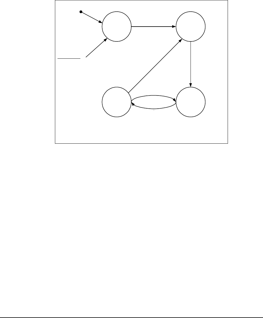
3 Detailed Description
36 APCD-LM043-4.0
3.5.2 MAC Layer (Polling MAC)
EUM States
The LMS4000 900 MHz Radio Network data transmission is based on a WaveRider’s
patented polling algorithm, which takes advantage of patterns found in typical Internet usage.
Based on the EUM’s subscribed grade of service and current traffic level, the Polling MAC
continuously adjusts the rate at which the EUM is polled. This process is illustrated in the EUM
State Diagram in Figure 22.
Figure 22 EUM State Diagram
When an EUM first powers up, it is in an unregistered state.
In the unregistered state, the EUM is not being polled and is therefore not passing traffic. As
outlined in EUM Registration on page 25, an unregistered EUM sends a registration_request
to the CCU. If the EUM is authorized in the CCU Authorization Table, it becomes registered/
disassociated.
In the registered/disassociated state, the EUM is still not being polled. But if the EUM has
traffic to send, it tries to associate with the CCU through the random access channel. The
EUM may also become associated iftheCCUhasapayloadtosendtotheEUM.Once
associated, the state of the EUM changes to active/associated.
In the active/associated state, the EUM is polled often, at a rate consistent with its subscribed
grade of service. If there is no traffic to or from an active/associated EUM for a defined interval
(typically set around 0.5 seconds), the state of the EUM changes to inactive/associated.
An inactive/associated EUM is polled less frequently than an active/associated EUM. If traffic
is resumed, the state of the EUM changes back to active/associated.Ifthereisnotrafficfora
longer defined interval (typically set around 2 seconds), the state of the EUM changes back to
registered/associated.
inactive/
associated active/
associated
unregistered registered/
disassociated
Random access for
EUM or payload for
EUM arrives at CCU
Traffic in either
direction
No traffic for ~0.5s
EUM is
not polled
EUM is
polled
often
EUM is
polled less
often
Notrafficfor~2s
Powerup
EUM is
not polled
regRequest/regResponse
From any state:
- deregRequest
- extended period with no traffic (~12h)
* Parameters are derived from the GOS
configuration file, and vary with EUM
grade of service.

3 Detailed Description
APCD-LM043-4.0 37
If an EUM is issued a deregistration request, for any reason, or if it has no traffic for an
extended period of time, 12 hours or so, its state changes back to unregistered.
Basic Operation of the Polling MAC
The Media Access Control (MAC) layer determines which unit (CCU or EUM) gets to transmit
and when it gets to transmit. Through the MAC layer, the CCU determines which associated
EUM gets to transmit next and indicates to the EUM that it can transmit by polling it. The
frequency with which an EUM is polled is based on its assigned Grade of Service (GOS). The
CCU transmits a directed poll to the EUM, which immediately transmits a response to the
CCU. After the response is received from the EUM, the CCU transmits the next poll. In this
way, the inbound (EUM-to-CCU) and outbound (CCU-to-EUM) channels are maintained
collision free.
If the CCU has data to send to an EUM, then that data is sent with the directed poll. If the EUM
has data to send to the CCU, then that data is sent with the EUM response to the poll.
EUMs that are not authorized are not polled.
To optimize polling efficiency, EUMs that no longer have traffic to send are not polled. EUMs
that are not being polled can submit a request to be polled by responding to a special random
access poll transmitted regularly by the CCU. Collisions may sometimes occur on this random
access channel; however, since only a small number of users are vying for service through the
random access channel at any one time, the effect on channel performance is negligible.
Recovery from these collisions is made possible by random back-off and retry.
Once again, if the EUM requesting service through the random access channel has data to
send to the CCU, it will be included with the request message. If the CCU has outstanding
broadcast messages to send, they will be sent to all EUMs with the random access poll.
An automatic repeat request (ARQ) scheme, using acknowledgements and retransmissions to
recover from message losses due to collisions or radio link errors, provides reliable transport.
Each transmitted data payload is numbered in the packet header. Each packet header also
contains an acknowledgement for the last correctly received payload, by number. If a CCU or
EUM does not receive an acknowledgement for a payload that it has transmitted, it retransmits
that payload with the following poll of, or response from, that EUM. A payload is transmitted a
maximum of four times, after which it is discarded. Note that contrary to the 802.11b system,
MAC-layer acknowledgements are not transmitted as separate packets, reducing overhead by
33%, on average.
Network Usage
The design of the Polling MAC has been optimized to allow maximized user capacity for
typical patterns found in Internet usage, which include browsing the world wide web,
accessing email, transferring files, and streaming audio and video. The common characteristic
of these uses is that they are bursty—data is transferred in bursts, with time in between the
bursts when no data is transferred. As a result, not all users will be transferring data at the
same time. In fact, the number of users that are actually transferring data at any one time is
generally much smaller than the number sitting in front of their computers which, in turn, is
much smaller than the total number of end users. As a result, many users can share the radio
link and, for the short time they need it, use a significant portion of the link bandwidth. In other
words, many users share the limited bandwidth of the channel, yet each perceives that they

3 Detailed Description
38 APCD-LM043-4.0
have most of the channel bandwidth to themselves. This over-subscription model is the basis
of Ethernet, DOCSIS cable networks, 802.11 radio networks, Bluetooth, and on a larger scale,
the public switched telephone network.
If a significant portion of the network traffic does not meet this typical bursty model, the Polling
MAC adjusts to maximize the user capacity. In this case, the maximum number of users is less
than the case where most of the traffic is bursty. As described in Specialized Applications on
page 155, the Polling MAC can also be optimized to support LMS4000 applications, which
have been designed, for example, to cost-effectively extend the coverage range.
Association
The Polling MAC has been designed to take advantage of the bursty, intermittent nature of
Internet usage through the concept of association. When users are transferring bursts of data,
their EUMs are associated with the CCU, and they are allocated a portion of the polling
sequence. In between bursts, the EUM is disassociated, freeing that part of the polling
sequence for other users. The determination of when to disassociate an EUM is based on the
time that has expired since any data was transferred to or from that EUM. As more and more
EUMs become associated, the bandwidth allocated to each EUM gets smaller and smaller,
consistent with the GOS constraints discussed below.
When an EUM is not associated but has data to send, it uses the random access mechanism
to send the first packet. On receiving this first packet, the CCU considers the EUM associated
and begins to poll it. The EUM remains associated as long as traffic continues to flow, but after
a short period of inactivity it is directed to disassociate.
If the CCU has data to send to a disassociated EUM, the status of the EUM changes to
associated, and the data is sent to the EUM the first time it is polled.
The maximum number of EUMs that can be associated at any one instant of time is 75. Any
EUMs trying to associate beyond this limit are denied access until the number of associated
EUMs falls below the limit.

3 Detailed Description
APCD-LM043-4.0 39
Grade of Service (GOS)
In the Polling MAC, the grade of service (GOS) determines how often, and when, an
associated EUM is polled. Since the EUM can only send one packet each time it is polled, the
data rate is related to the polling rate.
Operational objectives that are factored into the determination of the basic polling rate include
the following:
• Maximize overall user capacity and minimize the overhead related to empty polls.
• Accommodate different types of data; for example, short, bursty data, such as email
and browsing, and large file transfers.
• Support differentiation of user classes in terms of committed information and
maximum burst rate throughput levels.
• Control packet latency to support interactive services such as VoIP and chat.
• Support both symmetrical and asymmetrical data applications.
• Control unauthorized web hosting or gaming applications.
• Support multi-user network applications at a single EUM
To accommodate these often-conflicting operational objectives, WaveRider has designed a
patented Polling MAC layer that incorporates an integrated GOS management algorithm.
Within this algorithm, a total of 11 GOS parameters (GOS parameter set) are controlled to
achieve specific performance objectives.
To maximize the performance of the GOS algorithm, and therefore Polling MAC, control of the
following factors is key:
• Delay between packets transmitted to (or from) an EUM
• Relative weighting of different GOS classes
• Determination of when an EUM is active or inactive.
Manipulating these factors through the GOS parameter set can provide
• differentiated levels of service to end-users, which are defined in terms of average
committed and maximum burst throughput rates, and
• other special service classes.
The polling algorithm controls packet rates and timing, which in turn provide varying data
throughput in kbps, depending on the packet sizes for a given application.
GOS classes are defined based on particular combinations of the GOS parameter set. The
system operator assigns a GOS class to each EUM, and the CCU gets the EUM's polling
parameters from that class.

3 Detailed Description
40 APCD-LM043-4.0
In determining the order in which to poll the EUMs, the CCU tries to
• ensure consecutive polls of an EUM occur within the range defined by the EUM's
grade of service,
• maintain the average time between polls defined by the grade of service, and
• divide the total number of polls among EUMs consistent with the grades of service of
the EUMs being polled.
SinceitisinefficienttopollanEUMifthereisnodatatosendeitherway,anEUMcanbe
polled less often if it has not recently transmitted or received traffic. The GOS parameter set
essentially provides for independent control of the polling characteristics for both active EUMs
(those that have recently had traffic) and for inactive EUMs (those that have recently had no
traffic), where “recently” is defined by the GOS parameter set.
In addition to efficiently managing the usage of the radio link and providing differentiated
service capabilities, the polling MAC inherently smooths the upstream (EUM-to-CCU) packet
arrival times. It also has a smoothing effect on the downstream traffic arrivals, which positively
impacts network performance by reducing
• surges in data traffic,
• transients in queue occupancy, and
• packet discards.
GOS Configuration Files
Each GOS is defined by configuration files that are stored in the CCU. The CCU can maintain
up to five GOS configuration files, consisting of
• up to four assignable GOS configuration files, and
• one GOS configuration file for broadcast messages.
The operator assigns each EUM to one of the four assignable GOS configuration files, which
have the fixed labels of Gold, Silver, Bronze, and Best Effort. Although the labels are fixed, the
actual service level is determined by the configuration file that is associated with label.
Although only four assignable GOS configuration files can exist simultaneously in the CCU,
each of these files can be readily changed by FTPing a new configuration file to the CCU, to
replace the existing one. This change can be done while the CCU is active and takes effect
immediately.
As specific requirements are identified, WaveRider creates and makes available sets of
predefined configuration files. To illustrate the operation of the GOS configuration files, the
performance of the factory default GOS service levels is summarized in Table 8. This default
GOS configuration file is tailored for networks consisting of both residential and business-class
users.

3 Detailed Description
APCD-LM043-4.0 41
Table 8 Factory Default GOS Configuration File
NOTE: While recognizing that the performance of data transmission
through packet radio networks is randomly dependent on many
variables, typical FTP rates based on empirical data are included
in the table to demonstrate the performance that the operator
might expect on single, large FTP transfers using maximum-sized
packets.
There are several important observations that can be made about the above service-class
descriptions:
• All of the default service classes impose a limit on the maximum polling rate.
• The Silver and Gold service classes have a lower bound on the polling rate (12 and 22
polls per second [pps] respectively). The Polling MAC treats this limit as a minimum
committed level, which is subject to overall radio link capacity.
• In determining the order and frequency with which to poll EUMs, the CCU first tries to
ensure all associated EUMsarepollednomorefrequentlythanthemaximumservice
class polling rate, and no less frequently than the minimum service class polling rate.
• As the system usage increases, the end-user throughput in all classes decreases
from the maximum. Bronze users see the largest reduction, then Gold users, and then
Best Effort users. When all users have been reduced to 256 kbps (the minimum
threshold for Gold), the next reduction will be shared by the Best Effort, Bronze, and
Silver class users (Gold will not be reduced further), until the minimum threshold for
Silver is reached. After this, if further reductions are required, this reduction would be
shared equally between the Best Effort and Bronze users.
In practice, the bursty nature of Internet usage is such that this methodical reduction in
throughput is not apparent to the end-user, and these variations in service level tend
to be instantaneous and transitory. Overall, end-users tend to see a relatively high
average throughput consistent with their assigned GOS class, as is shown later in
detailed simulation results based on real user data.
Service
Class Polling Rate (polls/second) FTP Rate
(see note) Operator
Assigned
BestEffort 1-34 0-384kbps Yes
Bronze 1 - 90 0 - 1024 kbps Yes
Silver 12 - 22 128 - 256 kbps Yes
Gold 22 - 46 256 - 512 kbps Yes
Broadcast Varies with channel load,
from 16 to 935 Not applicable No
Denied 0 0 Yes

3 Detailed Description
42 APCD-LM043-4.0
Transmit Queue Limits
CCU transmit buffer space is a limited resource shared between the EUMs. If more traffic is
received at the CCU for transmission to an EUM than can actually be transmitted to it, that
EUM might eventually use up all available CCU buffer space, effectively starving all other
users. Therefore, the number of packets in each EUM's transmit queue is intentionally limited.
Packets arriving beyond this limit are discarded, resulting in retransmission of TCP/IP packets
by the host computer and TCP/IP adjusts by slowing down. The EUM transmit queue length
limit, which is never less than the lower bound given in the GOS parameter set, is dynamic and
based on total queue occupancy.
EUM transmit queue length limit determines the optimal TCP receive window size (the
maximum allowed number of outstanding unacknowledged bytes) used by the host
application. Some Internet Speed Boost programs intended for DOCSIS or ADSL
connections, simply increase the receive window size to very large values. This increase
results in very long queues at the CCU, more discarded packets, increased retransmissions,
and reduced throughput. To maximize throughput, WaveRider recommends setting the
receive window size of these applications to between 18000 bytes (~12 packets) and 24000
bytes (~16 packets).
TIP: Utilities are commercially available for optimizing the TCP
receive window size in the end-user’s computer, through
manipulation of the Windows registry.
Polling MAC Statistics
A wide range of Polling MAC statistics are recorded by the CCU and EUM. These statistics are
very useful, particularly during installation and as an aid to troubleshooting. A complete list of
statistics provided by entering the <stats mac> command through the CLI can be found in
Monitoring the Network on page 127.
Performance Modelling
The performance of packet radio systems like the LMS4000 900MHz Radio Network cannot
easily be derived from analytic calculations. However, using computer simulations that are
designed to accurately reflect the system implementation, and user and network traffic
distributions, it is possible to produce statistical representations of LMS4000 system
performance.
WaveRider has developed a model that simulates LMS4000 system processes, tasks,
protocols, propagation delays, and queue sizes. The model can simulate systems with large
numbers of EUMs and wide ranges of user traffic. The inputs to the model include
• number and geographical distribution (distance from CCU) of EUMs,
• user traffic statistics, and
• RF link-quality distributions.
These inputs are based on WaveRider’s experience with actual customer installations. The
outputs of the model are statistical representations of system performance.
3 Detailed Description
APCD-LM043-4.0 43
To illustrate the output of the model, consider the following example. First of all, make the
following general assumptions:
• LMS4000 900 raw channel rate is MHz 2.75 Mbps
• There are no channel errors
• Servers are fast and do not present a bottleneck
• There are no external link or backhaul bottlenecks
• TypicalCCUtoEUMrangeis0to3km
• GOS is unlimited
Furthermore, assume that typical end-user traffic is Web browsing, averaging one 60 kbyte
HTTP transfer every two minutes. This traffic pattern is based on analyses of busy-hour data
collected from LMS systems consisting primarily of residential users. In normal usage, users
randomly and independently download a file or Web page, take time to process the
information, and then download another file or Web page. Assuming this type of traffic, the
performance shown in Figure 23 results.
Figure 23 Net Throughput per EUM — 100 EUMs, 60 kbyte HTTP every 2 minutes
From Figure 23, each of the 100 end users can expect a net throughput better than 800 kbps
80% of the time, and better than 1.3 Mbps 20% of the time. You can also assess system
0
0.2
0.4
0.6
0.8
1
0 500 1000 1500 2000
Performance (kbps)
Probability that Performance was
Exceeded
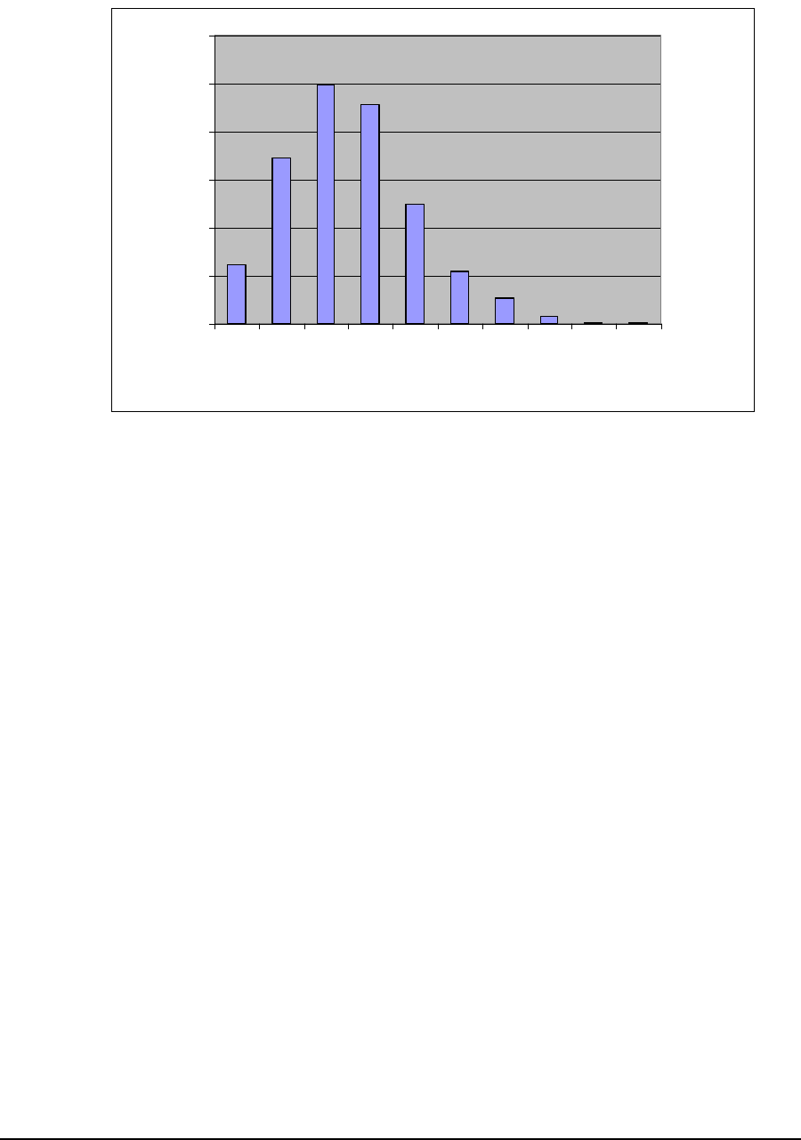
3 Detailed Description
44 APCD-LM043-4.0
performance based on the number of EUMs that are associated at any given time, as is
illustrated in Figure 24..
Figure 24 Associated EUMs — 100 EUMs, 60 kbyte HTTP every 2 minutes
Of the 100 EUMs, each is associated at random times and for random intervals, so the
probability of having more than ‘n’ EUMs associated must be determined statistically.
From Figure 24, 25% of the time only 2 of the 100 EUMs are associated at the same time.
Less than 1% of the time, there are only 7 associated EUMs. Even with 100 EUMs, where end
users are browsing and downloading during the same period, 6% of the time no EUM is
associated.
0
5
10
15
20
25
30
0123456789
Associated EUMs
Frequency (%)
3 Detailed Description
APCD-LM043-4.0 45
By increasing the number of EUMs to 300 and maintaining the same level of traffic per EUM,
the modelled performance becomes
Figure 25 Net Throughput per EUM — 300 EUMs, 60 kbyte HTTP every 2 minutes
From Figure 25, each of the 300 end users can expect a net throughput better than 300 kbps
80% of the time, and better than 750 kbps 20% of the time. Once again, you can assess
system performance based on the number of EUMs that are associated at any given time, as
is illustrated in Figure 26.
Figure 26 Associated EUMs — 300 EUMs, 60 kbyte HTTP every 2 minutes
From Figure 26,of300EUMs,eightwereassociated 12% of the time, and 14 were associated
less than 3% of the time. The amount of time 25 or more EUMs were associated was less than
0.4%.
0
0.2
0.4
0.6
0.8
1
0 500 1000 1500 2000
Performance (kbps)
Probability that Performance
was Exceeded
0
2
4
6
8
10
12
14
0
2
4
6
8
10
12
14
16
18
20
22
Associated EUMs
Frequency (%)

3 Detailed Description
46 APCD-LM043-4.0
All of these charts illustrate that many (LMS4000) users can share the limited bandwidth of
the channel, yet most of the time, each perceives that they have most of the channel to
themselves.
Atypical Applications
The Polling MAC has been optimized for normal user applications. One basic assumption that
has been made in the design of the Polling MAC is that users are only associated for a small
fraction of the time they are sitting in front of their computers. This usage is typified, for
example, by a file transfer (Web page for example) every two minutes or so—each transfer
taking a second or two. The MAC takes advantage of this usage pattern by only associating
with active EUMs.
A second assumption is that EUMs become active independently. If many EUMs
simultaneously attempt to use the random access opportunity, they will collide multiple times
and may not get through.
If the above assumptions are reasonable, then it is also reasonable to assume that a limited
number of EUMs will be associated at any given time, as demonstrated in Performance
Modelling on page 42.
There are several computer applications where usage is not consistent with the above
assumptions. These applications, which are discussed below, can compromise the efficient
operation of the LMS4000 network and may cause the network to slow down.
Broadcast Applications
Some applications broadcast messages to which all or a large number of hosts are expected
to respond. If these applications are running over the system, not only will responses from
disassociated EUMs collide as the random access opportunities are overwhelmed, but those
that do get through will quickly use up all of the available associations. With so many
associated EUMs, polls are farther apart and throughput degrades, even if the newly
associated EUMs have no further traffic to send. As well, EUMs that are not associated are not
able to associate and are therefore be blocked for a few seconds. The following applications
can cause this type of problem:
•Broadcast pings: WaveRider recommends not using broadcast pings.
•SNMP broadcast requests: WaveRider recommends not using SNMP broadcast
requests.
•Windows Network Neighborhood: This traffic can be blocked using port filtering at
the CCU or EUM level, as discussed in Port Filtering on page 49.
Periodic Packet Sources
Some applications send individual packets at fixed, often large, intervals, expecting only a
single packet or small number of packets in response. The direct impact of these applications
is that EUMs that are sent periodic packets remain associated for a longer period of time than
that warranted by their end-user traffic level and continue to be polled unnecessarily. The
atypical applications themselves will function very well; however, they will use up a significant
amount of the channel bandwidth. This group includes the following applications:

3 Detailed Description
APCD-LM043-4.0 47
•Pings (interval is typically 1 second): WaveRider recommends the operator avoid
running applications that generate a lot of pings, such as What’s Up Gold.
•Network gaming (interval is typically 0.25 seconds): WaveRider can provide a GOS
class for managing this kind of traffic if specific end users are running this type of
application.
•SNMP poll (interval is typically 30 seconds): This traffic is usually generated by the
operator. WaveRider recommends increasing the SNMP poll interval to a large value,
for example, greater than one hour and, if possible, that the SNMP application not poll
all EUMs in the same short interval.
TIP: Consult WaveRider for a special GOS Configuration File to
limit the impact of these atypical applications for specific EUMs.
Network Monitoring
Some applications send packets to each host on the network, usually to determine whether
the host is accessible and/or functioning. These applications, which may be run by the system
operator, cause EUMs that otherwise would not be associated to become associated. Often,
the additional load from applications of this type can even exceed the end-user traffic load on
the system. Since these applications tend to be periodic, the load is presented to the system
regularly over an indefinite period. Also, with large networks, application polling may soon
exceed the maximum number of associations. In this case, the application may not be able to
receive responses from some EUMs, presenting the operator with misleading status
information. This group includes the following applications:
•SNMP polling: As noted above, WaveRider recommends increasing the SNMP poll
interval to a large value, for example, greater than one hour, and staggering polls to
groups of EUMs.
•SNMP service discovery: Service discovery is not required for management of the
LMS4000 900 MHz Radio Network.
•Ping scripts,suchasWhat’s Up Gold: WaveRider recommends obtaining a tool to
stagger the pings.
Since the network operator controls most of the above applications, WaveRider recommends
limiting or at least delaying their use until non-busy hours.
Voice Over IP (VoIP)
Voice over IP (as opposed to streaming audio or video) requires small packets to be sent at
very short intervals — usually around 20 ms — with very little latency allowed in either
direction. While the LMS4000 900 MHz Radio Network may be able to support this level,
either as a guaranteed grade of service class parameter or on a best effort basis, VoIP
applications result in a high per packet overhead on the radio channel. This overhead and the
requirement for low latency mean the VoIP call occupies about 10% of the available bandwidth
for the duration of the call. It obviously does not take very many VoIP users to significantly
affect system performance. Also, unless this grade of service guarantee is given, the quality of

3 Detailed Description
48 APCD-LM043-4.0
the call may be affected as other users become associated, increasing the polling interval
beyond 20 ms. Since the grade of service applies to an EUM and not to an individual service,
a VoIP user would have to be given a very high grade of service, to the possible detriment of
other end users.
3.6 CCU and EUM Feature Description
3.6.1 DHCP Relay
IP address information for CCUs and EUMs are manually entered. In the case of end-user
PCs, IP addresses can be entered manually or obtained automatically from a DHCP server, if
CCU DHCP relay is enabled.
Once DHCP Relay is enabled in the CCU, DHCP requests from the end-user’s computer pass
transparently through the CCU and EUM to the operator’s DHCP server. Since the IP address
assigned to the end-user’s computer must be on the same subnet as the CCU radio port, the
operator needs to preassign an appropriate block of IP addresses in the DHCP server.
TIP: It is helpful to assign meaningful names, such as the
customer name, to customer computers or home network
routers. Then, if a DHCP server is implemented, the address
leases pool includes this name with the client IP address,
facilitating easier identification.
3 Detailed Description
APCD-LM043-4.0 49
The gateway router can provide DHCP server functionality, or you can implement a dedicated
DHCP server, as shown in Figure 27.
Figure 27 DHCP Relay
3.6.2 Port Filtering
The CCU and EUM both support TCP and UDP port filtering. The IP protocol suite is made up
of many subcomponents consisting of ports and protocols. Up-to-date listings of TCP and
UDP ports can be obtained off the Web. Some of these ports are required for normal LMS4000
operation, but most are not. The system operator can configure the CCU and EUM to filter
packets on specific TCP or UDP ports to improve network performance, security, or privacy.
For example, to prevent end-users from having visibility of, and access to, other end-users
through Windows Network Neighborhood, filter the following ports at the CCU for both UDP
and TCP packets:
• Port 137 NETBIOS Name Service
• Port 138 NETBIOS Datagram Service
• Port 139 NETBIOS Session Service
• Port 1512 Microsoft’s Windows Internet Name Service
CAUTION: The EUM is delivered with port filtering enabled.
CAUTION: Do not enable filters to block Telnet (port 23), FTP
(ports 20 and 21), or SNMP (ports 161 and 162); otherwise, you
will not be able to manage your network.
CCU3000
(with DHCP Relay enabled)
Antenna EUM3000
NMS Station
Switch
Internet
End-user Computer
(with DHCP enabled)
DHCP Server
DHCP
Request
DHCP
Response
(layer-2
messages)
DHCP
Request
(UDP)
DHCP
Response
(UDP)
Router
3 Detailed Description
50 APCD-LM043-4.0
3.6.3 SNTP/UTC Time Clock
The Simple Network Time Protocol (SNTP)/UTC feature provides LMS4000 devices with an
accurate clock for time stamping events in the log file.
SNTP/UTC Time Clock operation is illustrated in Figure 28.
Figure 28 SNTP/GMT Time Clock
The CCU, acting as an SNTP time client, regularly resynchronizes to one of several NTP
Servers from which it obtains UTC (Universal Coordinated Time). The CCU resynchronization
and retry periods can be set by the operator. The resynchronization period is the time between
a successful CCU resynchronization and the next CCU resynchronization attempt, typically
set to one hour. The retry period is the time between an unsuccessful resynchronization
attempt and the next resynchronization attempt, typically set to 30 seconds.
The operator can configure the CCU to act as an SNTP time server to the EUMs and
broadcast time information to all EUMs after it has synchronized with the NTP server. It also
broadcasts this information whenever an EUM powers up and registers.
UTC, the international time standard, is based on a 24-hour clock. It is the current term for
what was commonly referred to as Greenwich Mean Time (GMT). Universal time is based on
a 24 hour clock. SNTP, specified in RFC1769 and RFC2030, is a simplified version of NTP,
which is specified in RFC1305.
By default, the CCU SNTP client is disabled.OnceSNTPisenabled, the CCU tries to
synchronize with an NTP server. The operator can configure the CCU to synchronize with
• a local router or network device, if the router or network device is configured as an
NTP time server,
• any open-access NTP server of the operator’s choosing, or
• one of the five factory-default open-access NTP servers listed below:
• 132.246.168.148 time.nrc.ca stratum 2, Canada
• 140.162.8.3 ntp.cmr.gov stratum 2, US
• 136.159.2.1 ntp.cpsc.ucalgary.ca stratum 2, Canada
• 192.5.5.250 clock.isc.org stratum 1, US
• 127.0.0.1 local host (the CCU itself)
CCU3000
Antenna EUM3000
NTP Server
Internet
Time Request
Time
Time
Broadcast

3 Detailed Description
APCD-LM043-4.0 51
CAUTION: The local host entry, 127.0.0.1, is required to avoid
the problem where the CCU cannot find a real NTP server (i.e., if
the network is down).
3.6.4 Customer List
For each EUM, the system operator can control the number of end-user computers that can
access the LMS4000 network for the purpose of controlling network performance or service
differentiation. The use of this list is described in Customer Table (EUM only) on page 192.
3.6.5 SNMP Support
Simple Network Management Protocol (SNMP) allows a network management server to
monitor, control, and remotely configure LMS4000 network devices. In SNMP, these devices
are also referred to as agents.
Community Strings
Community strings act as passwords to facilitate communication between the SNMP server
and a network device. There are three types of community strings:
•Read community strings, which enable SNMP servers to retrieve information from a
network device
•Write community strings, which enable SNMP servers to send information, such as
configuration commands, to a network device.
NOTE: At this time, there are no writable SNMP MIB entries. All
configuration is done via the CLI.
•Trap server IP address and community strings, which enable SNMP servers to
receive unsolicited messages from a network device. These unsolicited messages
indicate asynchronous events, such as an interface going down or coming up, a unit
performing a cold or warm start, or an operational failure.
Each network device monitored by SNMP must have at least one of each type of community
string defined. Each CCU and EUM can have up to five read or read/write and five trap
servers/community strings defined. Non-WaveRider devices may have only one of each type
of community string defined. Community strings are case sensitive.
Table 9 Factory Configured Community Strings
Community String Type Community String
Read public
Write private
Trap <none>

3 Detailed Description
52 APCD-LM043-4.0
CAUTION: By convention, most equipment ships with the
default community strings defined in Table 9. WaveRider
recommends that you change the community strings before you
bring the LMS4000 equipment online, so that outsiders cannot see
information about the internal network or configure system
components.
Management Information Bases (MIBs)
All messages sent between the SNMP server and a network device are based on number
codes. Each of these number codes corresponds to a specific type of information (such as the
quantity of data packets received) associated with a specific type of network device (such as a
CCU). These number codes and their meanings are stored in a management information base
(MIB). The SNMP server and network devices use these MIBs as lookup tables for translating
messages sent between them.
LMS4000 implements SNMPv2c and includes a number of standard and enterprise MIBs:
• RFC1157 (MIB-Il)
• RFC1493 (bridging)
• WaveRider Enterprise MIB (defined in Appendix G on page 199)
You can download WaveRider Enterprise MIBs, which include a comprehensive set of CCU
and EUM parameters and statistics, from the technical support page at www.waverider.com.

APCD-LM043-4.0 53
4IP Network Planning
This section describes a plan for assigning IP addresses to LMS4000 900 MHz Radio Network
components.
4.1 LMS4000 IP Addressing
Before discussing IP planning, there are a few concepts that are worth reviewing. The first
concept is that in the LMS4000 900 MHz Radio Network, IP addresses are assigned to
devices for several reasons:
• The device is a router, such as the gateway (NAP) router or the CCU. IP addresses
are required for each router port.
• The device is a destination or source for user data. End-user PCs and network
servers (such as DHCP servers) fall into this category.
• The operator wants to configure, control, or monitor the device. Virtually all LMS4000
components fall into this category.
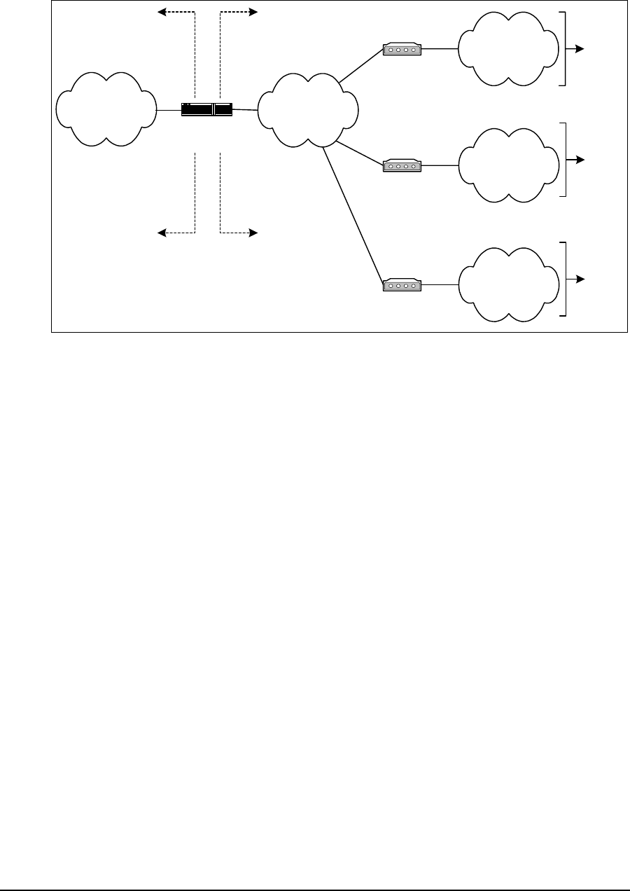
4 IP Network Planning
54 APCD-LM043-4.0
The second concept is the segmentation of the LMS4000 network into distinct subnets, as
illustrated in Figure 29.
Figure 29 LMS4000 Subnets
Routers isolate the subnets from each other or from the Internet. The router application
isolates the CCU radio subnets from the CCU Ethernet subnet, and the gateway (NAP) router
isolates the CCU Ethernet subnet from the public Internet.
The number of CAPs that can be supported by one gateway is limited only by the capacity of
the gateway router. If a system has 15 CAPs, each supporting three CCUs, the system
consists of 45 radio subnets.
The radio subnets extend from the CCU radio port through the EUMs to the end-user PC
Ethernet ports. Each radio subnet includes the following elements, all of which, from the
standpoint of the LMS4000 network, require a unique, most likely private, IP address:
• CCU radio port one per radio subnet
• EUM up to 300 per radio subnet
• End-user PC (or LAN router)
• Ethernet port one per EUM (up to 300 per radio subnet)
Based on the above, each radio subnet requires a maximum of 601 IP addresses, which
necessitates a subnet with a 22-bit subnet mask, which provides 210 = 1024 addresses.
The CCU Ethernet subnet extends from the CCU Ethernet port through backhaul facilities and
Ethernet switches to the gateway (NAP) router Ethernet port. The CCU Ethernet subnet
includes the following elements, all of which, from the standpoint of the LMS4000 network,
require a unique IP address:
• CCU Ethernet ports
• RFSMs,ifprovisioned
Gateway (NAP)
Router
Internet
CAPn, CCUm
Router Application
CAP01, CCU01
Router Application
CCU Ethernet
Subnet
CAPn, CCUm
Radio Subnet
CAP01, CCU01
Radio Subnet End
Users
End
Users
Private NetworkPublic Network
... ... ...
... ... ...
CAP15, CCU03
Router Application
CAP15, CCU03
Radio Subnet
End
Users

4 IP Network Planning
APCD-LM043-4.0 55
• CAP-NAP backhaul equipment, if provisioned
• CAP and NAP UPS, if provisioned
• Ethernet switches
• SNMP manager, if provisioned
• Gateway (NAP) router Ethernet port
The number of CAPs is limited by the capacity of the gateway (NAP) router. WaveRider
suggests allocating a minimum of 256 addresses to the CCU Ethernet subnet, which
accommodates 15 CAPs and requires a 24-bit subnet mask.
4.2 IP Planning Process
For reference purposes, an example of an IP Plan is included in Appendix I on page 241.
Before you configure and operate your LMS4000 900 MHz Radio Network, you must define
your IP addressing scheme based upon the following guidelines and recommendations:
• WaveRider recommends that LMS4000 subnets use IP addresses that have been
reserved for private networks. WaveRider recommends 192.168.10.0 /24 for the CCU
Ethernet subnet, and 10.0.0.0 /22 for the CCU radio subnet, since these addresses
are quite distinct from each other. If you are already using 10.0.0.0 /22, then you can
alternatively use 172.16.0.0 /22.
• The IP addressing plan for the CCU Ethernet subnet should allow for growth to a
maximally equipped system, as follows:
• CCU Gateway IP address one
• NAP equipment IP addresses up to 10
• CAP equipment Ethernet IP addresses number of CAPs x 16
For a 15-CAP system, set aside 251 IP addresses, which requires a subnet with a 24-
bit mask, for example 192.168.0.0 /24.
In the example shown in Appendix I on page 241, the IP addressing plan for the CCU
Ethernet subnet is summarized as follows:
CCU Ethernet Subnet 192.168.10.0 /24
Gateway Router 192.168.10.1 /24
NAP Switch 192.168.10.5 /24
NAP UPS 192.168.10.6 /24
SNMP Manager 192.168.10.7 /24
CAP01, CCU01 Ethernet port 192.168.10.11 /24
CAP01, CCU02 Ethernet port 192.168.10.12 /24
CAP01, CCU03 Ethernet port 192.168.10.13 /24
CAP02, CCU01 Ethernet port 192.168.10.27 /24
.....
CAP15, CCU02 Ethernet port 192.168.10.236 /24

4 IP Network Planning
56 APCD-LM043-4.0
CAP15, CCU03 Ethernet port 192.168.10.237 /24
• As noted above, the IP addressing plan for each CCU radio subnet should allow for
growth to a maximally equipped system. Providing 601 IP addresses on the same
subnet requires a subnet with a 22-bit mask, for example 172.16.0.0 / 22.
In the example shown in Appendix I on page 241, the IP addressing plan for the CCU
radio subnets is summarized in Table 10:
Table 10 Example — CCU Radio Subnet IP Addressing
• The end-user PC Ethernet IP address can be entered statically, or dynamically using
DHCP. If DHCP Relay is enabled in the CCU, which WaveRider recommends, and the
system operator has installed and properly configured a DHCP server in the network,
then the end-user computer can be simply configured to automatically request its IP
address from the DHCP server. The operation and configuration of DHCP Relay is
discussed in DHCP Relay on page 48. To use DHCP, the system operator must
allocate, for each CCU radio subnet, a pool of IP addresses from the CCU subnet,
such as the contiguous sets of end-user PC IP addresses defined in Table 10.
• If you are using unregistered IP addresses for the EUMs and end-user PCs, these
addresses must be translated to globally unique Internet registered addresses before
they leave the private domain. Although the CCU functions as a router, it does not
provide address translation.
For end users to access the Internet, you must provide NAT (Network Address
Translation). Normally, NAT is provided in the gateway (NAP) router. Refer to section
4.3, Network Address Translation for further information.
CCU CCU Radio
Port EUM Range End-user PC Range
CAP01, CCU01 172.16.4.1 172.16.4.2 - 172.16.5.47 172.16.6.1 - 172.16.7.46
CAP01, CCU02 172.16.8.1 172.16.8.2 - 172.16.9.47 172.16.10.1 - 172.16.11.46
CAP01, CCU03 172.16.12.1 172.16.12.2 - 172.16.13.47 172.16.14.1 - 172.16.15.46
CAP02, CCU01 172.16.16.1 172.16.16.2 - 172.16.17.47 172.16.18.1 - 172.16.19.46
... ... ... ...
CAP15, CCU02 172.16.176.1 172.16.176.2 - 172.16.177.47 172.16.178.1 - 172.16.179.46
CAP15, CCU03 172.16.180.1 172.16.180.2 - 172.16.181.47 172.16.182.1 - 172.16.183.46

4 IP Network Planning
APCD-LM043-4.0 57
4.3 Network Address Translation
The following address translation alternatives are listed for reference purposes. Choose the
best alternative for your system. Your choice depends on the number of available registered
IP addresses. It also depends on the nature of your subscriber base; for example, static NAT
may be required to support some of your business users, but dynamic NAT may be adequate
for most of your home users.
Static NAT
Static NAT maps an unregistered IP address to a registered IP address on a one-to-one basis.
This method of translation is recommended if, for example, end users are using VPN facilities
to access remote applications.
Dynamic NAT
Dynamic NAT maps an unregistered IP address to a registered IP address, taken from a pool
of registered IP addresses. This method of translation is useful when you have a large number
of unregistered users who wish to access the Internet. Depending on the traffic pattern, 10
registered IP addresses may be able to serve 40 end users.
Overloading
Overloading, which is a form of dynamic NAT, maps multiple unregistered IP addresses to a
single registered IP address by using different ports. This technique is also known as port
address translation (PAT), single-address NAT, or port-level multiplexed NAT. PAT greatly
reduces the number of necessary registered IP addresses. When overloading is configured,
the router maintains enough information from higher-level protocols to translate the registered
address back to the unregistered address for traffic inbound from the Internet.
—This page is intentionally left blank —

APCD-LM043-4.0 59
5Radio Network Planning
An important task in the implementation of LMS4000 900MHz Radio Networks is RF system
planning and design. Whether you are deploying a single CCU or a complex multi-CAP, multi-
CCU network, proper system design is necessary to provide and maintain high-quality service
to end users in your target serving area.
5.1 Design Methodology
The following sections are not intended to provide detailed system design instructions;
instead, they provide system design guidelines. WaveRider used this approach for the
following reasons:
• Factors affecting system design and implementation vary widely and differ from
system to system.
• System design and implementation cannot be encapsulated in a simple formula or set
of formulas.
Each system design is unique and must take into account all of the design factors that can
influence system operation and performance:
• Topography: Hills and valleys that create coverage holes or conversely, areas that
may be very exposed from an RF standpoint, exposing subscribers in these areas to
high levels of interference generated from outside the system or by other CAP sites.
• Clutter: Obstructions such as trees and buildings, which tend to reduce the desired
signal level and coverage.
• Network Topology: The configuration of the network, implemented to provide optimum
service. Network topology is driven by factors such as the location of the Internet point
of presence, the availability of towers and roof-top locations that can be used to
establish antenna and equipment sites, and the target coverage area.
• Interference: The presence of interference, either in-band (in the ISM band) or out-of-
band in your target serving area constrains the freedom that you have for determining
the location of CAP sites and for choosing operating frequencies.

5 Radio Network Planning
60 APCD-LM043-4.0
In all cases, these wide-ranging factors drive the system design and as a result, no two
systems will be implemented the same way.
The design methodology presented in this chapter uses a building-block approach. If the
system you are designing is based on a single CCU, you need only read and learn about the
guidelines presented in Basic System Design on page 60. If you need multiple CCUs or CAPs
to satisfy your network requirements, you must perform a much more detailed engineering
design based on the general guidelines provided in Multi-CAP RF Network Design
Considerations on page 67.
For purposes of illustration, coverage areas are presented using the popular cellular
hexagonal coverage pattern. In practice, radio coverage does not conform to hexagonal
shapes; however, hexagons are used to represent radio coverage because graphically, they
can fully cover a plane surface and because they provide an easy-to-understand
representation of coverage cells.
5.2 Basic System Design
Basic system design guidelines apply to all LMS4000 system implementations, from a simple,
single-CCU system, to more complex multi-CCU CAPs and multi-CAP networks.
5.2.1 Overview of Basic System Design
The basic design of the LMS4000 900MHz radio network involves the following procedures:
• Conducting a spectral survey to identify, quantify, and assess the impact of existing
in-band and out-of-band interference.
• Determining single- or multi-CAP system requirements based on RF coverage, CAP
locations, and system loading.
5.2.2 Spectral Survey of the Target Service Area
Before starting the system design, WaveRider recommends conducting a spectral survey of
the target serving area to determine the radio landscape—that is, to determine if there are any
in-band or out-of-band interferers and how, and to what degree, these interferers constrain
your system design (site location, frequency, equipment).
The spectral survey involves travelling to key locations throughout the target serving area,
especially to locations that may be potential CAP sites, or where there are significant numbers
of potential end users, and recording the radio spectrum (ISM band +/- 10MHz) at each of
these locations. The survey requires the use of a spectrum analyzer and a trained RF
engineer who is capable of interpreting the results. There are a number of independent RF
engineering firms that can provide this service, including the WaveRider Professional Services
Group. If you have access to the required equipment and in-house skill set, you can also
conduct this survey yourself.
The spectral survey is a critical first step in the system design. Not only does it provide the
starting point for the RF network design, it establishes a baseline for the use and occupancy of

5 Radio Network Planning
APCD-LM043-4.0 61
the spectrum. Keep in mind that one of the major attractions of the ISM band is the fact that it
is license free; as such, it is shared spectrum. To regulate the band, regulatory bodies, such
as FCC and Industry Canada, require that new operators in the band take responsibility for
resolving interference issues when their newly installed system interferes with systems that
are already in operation. The spectral survey identifies systems that are operating in the ISM
band and establishes a documented baseline, which may provide you some protection from
future ISM-band installations that interfere with the operation of your system.
It cannot be overemphasized that radio communications is, by nature, a non-static
environment. As a wireless ISP, the more you know about the RF environment in which you
are operating, the better prepared you will be to address future service-affecting changes in
this environment. Given that the RF environment is dynamic, WaveRider recommends
performing spectral surveys on a regular basis, perhaps every 3-6 months.
5.2.3 In-band Interference
In-band interference occurs when other wireless systems are operating in the same band and
in the same geographical area as your system. The impact of in-band interference may be
limited—that is, the unwanted signal level may be so low as to have no impact at all, or it may
only affect service to a single end user or a small number of end users. In-band interference
may, however, be system wide, particularly if it is geographically dispersed around your
serving area or it is in close proximity to the CAP. System-wide interference obviously causes
the most impact to system operation since it affects all end-users in the serving area.
A primary purpose of the spectral survey is to identify in-band interference so that, if it is
present, the RF network design can address the interference sources through careful location
of the CAP, equipment configuration, and frequency selection, with the goal of maximizing the
ratio of the desired to the interfering signals throughout the serving area. If these measures
are not adequate, channel filters can in many cases reduce the interference to levels within
the operating tolerance of the LMS4000 radio equipment. Channel filters are discussed in
Using Bandpass Filters at CAP Sites on page 63.
5.2.4 Out-of-band Interference
The radio spectrum is a finite commodity, which in the growing world of wireless
communications, means that all users must compete for this limited resource. The implication
is that throughout the service life of your LMS4000 system, you need to be aware of your “RF
neighbors” and the impact they may have on your system operation and performance. As
described in Physical Layer (DSSS Radio) on page 28, the LMS4000 900MHz product
operates in the 902–928MHz ISM band. In many areas of the world, including North and
South America, the 900MHz ISM band is sandwiched between the top end of the cellular radio
band and the bottom end of the commercial paging band.
Cellular radio and paging systems are common in many regions, so you must take precautions
when planning your LMS4000 900MHz radio network. Specifically, you need to know the
location of all cellular and paging transmitters that are in, close by, or planned for, your serving
area, so that you can limit the impact of these potential interferers through proper site location,
equipment configuration, and frequency selection.
5 Radio Network Planning
62 APCD-LM043-4.0
Figure 30 shows an actual spectral sweep, recorded using a spectrum analyzer as part of a
spectral survey, which shows the location of the cellular and paging transmitters in relation to
the ISM band. Note the relative levels of the interfering signals.
Figure 30 Example of a Spectral Sweep
Cellular and paging systems in the bands adjacent to the ISM band can interfere with your
network and need to be addressed as follows:
• Identify and quantify all potential sources of interference by conducting and applying
the results of the spectral survey.
• If your CCUs or EUMs are close to cellular or paging sites, their receivers may be
desensitized by the high levels of the interfering transmitters, which can operate at
very high levels (100 W per cellular radio carrier, 1500W for paging transmitters). To
provide service to these EUMs, choose an operating frequency that is as far from
these cellular and paging transmitters as possible.
Try to assign frequencies that are not adjacent to the cellular or paging channels
identified in your serving area. Consider the scenario illustrated in Figure 31.As
shown, a cellular tower is located in sector A of the LMS4000 radio network. Since
cellular frequencies are located just below the ISM band, a reasonable design
Cellular Radio
Transmitters
Paging
Transmitters
ISM Band
5 Radio Network Planning
APCD-LM043-4.0 63
approach would be to assign a higher frequency to sector A, such as 915MHz or
925MHz.
Figure 31 Network Design in the Presence of Out-of-band Interference
5.2.5 Using Bandpass Filters at CAP Sites
WaveRider provides high-quality, specially designed bandpass filters for use with the CCU.
These filters reduce the effect of unwanted out-of-band and off-channel in-band interference.
As discussed in Propagation Path on page 31, it is highly desirable to locate the CAP site so
that the CCU antennas are high enough to provide clear line of sight paths to the maximum
number of EUMs in the serving area. The goal is to make sure the CCU can see the maximum
number of EUMs and conversely, to make sure the maximum number of EUMs can see the
CCU.
Attaining this goal, however, has a consequence since it may mean the CCU will be in an ideal
location to see interferers in its sector as well. Bandpass filters at the CCU reduce the effect of
interference from out-of-band or off-channel in-band interferers.
On-channel interference may result from
• on-channel interferers in the ISM band, or
• transmitter phase noise or intermodulation products generated by out-of-band
interferers.
Bandpass filters cannot resolve on-channel interference; instead, you must change to a more
suitable CCU operating frequency.
For CAP sites in which multiple CCUs are installed, use of bandpass filters to ensure non-
interfering operation of CCUs is mandatory. It is important to remember that in the 900 MHz
ISM band, the radio transmit and receive occur on the same frequency and use Time Division
Duplexing (TDD) to switch between the transmit and receive cycles. Multi-CCU installations
pose the highest threat of CCU to CCU adjacent channel interference. For the RF network
Sector C
Sector A
Sector B
Cellular
Transmitter
CAP

5 Radio Network Planning
64 APCD-LM043-4.0
engineer, as specified in Appendix A Specifications, the minimum separation between
colocated channels is 6.6 MHz (an orthogonal adjacent channel) and requires a C/I ratio of 50
dB or better for non-interfering CCU operation. Once the antenna system gains and power
output of the CCU radio are accounted for, the only way to practically provide adequate
isolation for the required adjacent channel isolation is through the use of bandpass filters.
5.2.6 Single- or Multi-CAP Implementation
An important step in basic system design is to determine if a single CAP site adequately
covers your target serving area, or if a second CAP site, or multiple CAP sites, will be
required. The main factors that drive this decision are the RF coverage and the system
loading.
RF Coverage
The RF coverage of the sector is a function of many different factors.
Commercially available radio coverage prediction software calculates radio coverage based
on the following factors:
• Propagation characteristics (frequency, distance from the site)
• Radio characteristics (transmit power, receiver sensitivity)
• Antenna system and height
• Topography
• Clutter
Using this coverage prediction software, a qualified RF design engineer is able to produce RF
coverage estimates. Again, there are a number of independent RF engineering firms that can
provide this service, including the WaveRider Professional Services Group. If you have the
required software and in-house skill set, you can perform this coverage analysis yourself.
5 Radio Network Planning
APCD-LM043-4.0 65
The location of the CAP site in relation to the serving area determines whether the site will be
a corner- or center-illuminated cell. Figure 32 illustrates the difference between these two
methods of illumination.
Figure 32 Corner- and Center-illuminated cells
Although the difference between the two approaches may seem academic at first, the choice
you make affects the system design, in particular, the selection of sites, site antennas, and the
system growth path.
Center Illumination
A center-illuminated cell is generally the simplest to implement. In this case, a site is
established at a suitable location near the middle of the target serving area. An omnidirectional
antenna is usually installed to deliver 360-degree coverage around the site.
When system traffic increases beyond the capacity of a single CCU because, for example,
many subscribers have been added to the system, more CCUs can be added to the CAP site
(up to a total of three operating CCUs per CAP site). The omnidirectional antenna would, in
this case, be replaced with sectored antennas, for example, three 120-degree sectored
antennas. The selection of the sectored antennas would depend on how evenly the
subscribers are distributed throughout the serving area. In this example, the resulting
CAP
CAP
Center-
Illuminated Cell
Corner-
Illuminated Cell
Serving Area
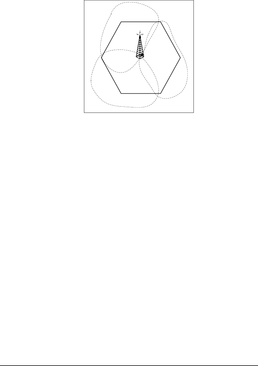
5 Radio Network Planning
66 APCD-LM043-4.0
configuration would triple the traffic-handling capacity of the site. Figure 33 illustrates the
sectoring of a previously center-illuminated omnidirectional cell.
Figure 33 Sectored Cell
Corner Illumination
Corner illumination is generally used when it is not possible to establish a suitable CAP site
near the middle of the target serving area. Implementation of a corner-illuminated cell requires
more extensive site and system engineering than does the implementation of a center-
illuminated cell. This is particularly true when additional traffic-handling capacity is required,
since techniques such as overlay/underlay sectors (adding a second CCU to provide coverage
to the same geographical area) may have to be applied.
The use of omni-directional antennas at CAP sites, although simple in implementation, is only
recommended for simple network installations with low risk of interference and limited
exposure to other sites. Omni-directional antennas, by definition, are designed to provide
coverage in all directions (360°) horizontally around the antennas. This wide angle-of-view
provides for simplicity of an omni-directional antenna installation but also means that the omni-
directional antenna is susceptible to any interference in the area. As such, the RF network
designer, when faced with interference or system expansion will generally need to replace the
omni-directional antenna(s) (and possibly multiple CCUs) in order to serve the same coverage
area and to make use of the directional properties of the antennas to address system issues.
System Loading
Sometimes, even with well-engineered RF coverage, the user traffic may be so high that you
need to expand the network to a multi-CAP system.
The answer to the question “How many subscribers can each CCU support?” is a qualified “It
depends.” Refer to Performance Modelling on page 42 for a description of the method used by
WaveRider to predict the number of end-users that can be supported by the LMS4000
network. Total system traffic is very dependent on the usage profile of the end users and the
tariff structure that has been implemented by the system operator. For instance, an LMS4000
900MHz system that is providing service to a number of small businesses, each supporting
CAP

5 Radio Network Planning
APCD-LM043-4.0 67
multiple users, likely generates a lot more daytime traffic than a simple residential service
used for Web browsing and email.
In summary, the network design engineer must be aware of the intended use of the system —
the customer profile, tariff rates, and committed grades of service — since these factors all
influence the traffic demand on the system.
5.3 Multi-CAP RF Network Design Considerations
One of the differentiating features of the LMS4000 900MHz radio system is its ability to
support multi-CAP networks. The design of multi-CAP networks is significantly more complex
than the design of single-CCU or single-CAP systems. WaveRider highly recommends the use
of a qualified RF engineering firm, such as the WaveRider Professional Services Group, to
carry out multi-CAP system design. If you are confident that you have the required skill set
available in house, you can carry out this design yourself.
5.3.1 Multi-CAP Network Design Process
The process for designing a multi-CAP network can be summarized as follows:
1. Conduct a preliminary site survey and selection.
2. Apply a frequency grid to the sites that you have selected.
3. Determine the site-to-site signal levels by
• Determining site-to-site distances,
• Calculating site-to-site propagation loss,
• Normalizing the signal levels at each site, and
• Factoring in the antenna isolation.
4. Using the C/I information presented in C/I Requirements on page 68, formulate a
frequency plan and channel assignment.
5. Perform and apply antenna down-tilt calculations.
6. Assess the impact of known in-band and out-of-band interferers.
7. Verify and iterate the design as many times as necessary.
This chapter does not provide detailed instructions on how to carry out each of the above
tasks as it is beyond the scope of the document. It does, however, provide you with the
LMS4000-specific information that you or your RF engineering firm need to be able to carry
out the above steps.
5.3.2 Frequency Selection — Standard Frequency Set
LMS4000 900 MHz equipment (CCUs and EUMs) can operate on all channels from 905 to
925 MHz, in increments of 0.2 MHz (refer to Table 6 on page 29 for channelization

5 Radio Network Planning
68 APCD-LM043-4.0
information). Throughout this manual, however, WaveRider has referred to the standard
frequency set shown in Table 11.
Table 11 Standard Frequency Set
The standard frequency set represents a convenient and safe set of frequency assignments.
The frequencies are orthogonal in that they do not overlap, and they provide enough
separation between the frequencies so that one channel does not interfere with either of the
other channels, even if they are installed at the same CAP site with appropriate filters. Using
the standard frequency set, you can implement small systems without much concern for self-
generated interference.
In the case of a multi-CAP network, however, the standard frequency set may not be
inadequate. Instead, you must use other sets of frequencies at neighboring CAP sites. The
selection of these other frequency sets is governed largely by the minimum C/I requirement for
the CCU and EUM radio; i.e., the amount of interference, from within or from outside the
system, that the LMS4000 radio equipment can tolerate.
5.3.3 C/I Requirements
The CCU/EUM C/I requirements are outlined in Table 12.
Table 12 Required C/I Ratio for Multi-CAP Design
As shown in Table 12, as the frequency separation between the desired LMS4000 signal and
an interfering LMS4000 signal increases, the level of an interfering signal that can be tolerated
also increases. Consider the case where the frequency separation between the desired
channel and an interfering channel from a remote site is 0.2 MHz. To maintain a packet error
rate of 1% in the local cell, you would need to ensure that the EUMs in the local cell are
receiving the desired CCU signal at a level which is at least 22dB higher than the interfering
CCU signal, 0.2MHz away.
Using this information, and information about the number and location of the required CAP
sites, your RF designer should be able to define a frequency plan for your system.
905.0MHz
915.0MHz
925.0MHz
C/I Ratio Frequency Separation PER
22dB 0.2MHz < 1%
19dB 1.6MHz < 1%
11dB 3.4MHz < 1%

5 Radio Network Planning
APCD-LM043-4.0 69
As an example, consider the frequency plan shown in Table 13.
Table 13 Sample Frequency Plan — Multi-CAP Design
In Table 13,Frequency Set A uses the minimum frequency spacing that should be considered
for a single CAP site, 6.6MHz. Frequency Set A’ represents a set of channels which are
interstitial to those in Frequency Set A. The channels in Frequency Set A’ fall midway between
the channels in Frequency Set A yet still adhere to the minimum recommended spacing
between any two colocated channels, 6.6MHz.
From Table 12, if two sites have a frequency separation of 3.4 MHz (Frequency Set A to
Frequency Set A', for example), a C/I signal margin of 11dB is required.
CAUTION: The concept of frequency reuse patterns, commonly
used in the design of cellular radio systems, cannot be directly
applied in the design of LMS4000 900MHz radio networks.
Instead, due to the nature of the Polling MAC, you should never
reuse frequencies in networks where a CCU or EUM can receive a
signal from a unit in another sector or coverage area. The
minimum channel separation cannot be less than 0.2MHz s a
minimum. When Polling MAC is applied in a multi-CAP
environment, it is possible for an EUM to inadvertently lock onto
the signal from a remote CCU if that CCU is operating on the
same frequency. This situation does not occur if the remote CCU
is offset by 0.2MHz or more from the local CCU, and the required
C/I ratio is maintained. In summary, no two CCUs in a single
network can be assigned exactly the same frequency .
5.3.4 Dealing with External Interference
Up to this point, the discussion has been concentrating on the effect of self-generated
interference—that is, interference between CAPs or EUMs in the same network.
As indicated in Basic System Design on page 60, you must also account for the effect of
external interferers such as cellular and paging systems. The RF system design engineer
needs to make sure external interference sources do not affect system operation. You can use
a similar treatment to the one developed above for self-generated interference to assess the
effects of external interference sources.
5.3.5 Verifying the Design
No matter how carefully the system has been designed, you must verify the system in the field
before turning it up to ensure network operation is consistent with the design standards set out
by the system design engineer. With this in mind, your system implementation plan must
Frequency Set A 905.0 - 911.6 - 918.4 - 925.0
Frequency Set A’ - 908.4 - 915.0 - 921.6 -

5 Radio Network Planning
70 APCD-LM043-4.0
provide enough time and resources for the engineering team to verify the design in the field
through testing and signal-level measurements.
Once you have established your CAP sites on the air, you can verify received signal levels
throughout the network using a portable spectrum analyzer. You can then compare these with
those predicted by the RF system design. In many cases, discrepancies between predicted
and actual results can be corrected, if necessary, through adjustment of antenna azimuths
and/or down-tilting.
As the system grows and capacity is added, the frequency plan may have to be adjusted and
more attention given to fine-tuning the isolation between CAP sites.
Verification Checklist
When reviewing and verifying the design of a multi-CAP network, here is a checklist of items
that might be considered:
• General system design considerations:
• Paging transmitters
• Cellular transmitters
• In-band interference
• Frequency assignments
• CAP-to-CAP frequency assignments and isolation, achieved through
• Lowering antenna heights,
• Antenna mounting, and the use of mounting structures to achieve greater
isolation (building, towers),
• Antenna radiation patterns (directionality and side lobes), and
• Antenna characteristics, back to front isolation.
• CAP-to-EUM propagation must provide coverage to all EUMs from selected sites. Run
the RF model with the specified system parameters to verify thorough propagation.

5 Radio Network Planning
APCD-LM043-4.0 71
5.3.6 Summary of RF Design Guidelines
A summary of guidelines presented in this chapter can be found in Table 14.
Table 14 Summary of RF Design Guidelines
DO DO NOT
• DO read and understand this chapter
before you start your system design
activity.
• DO contact WaveRider Professional
Services Group if you need assistance
with spectral surveys, RF coverage
analyses, or system engineering.
• As a first step, always DO a spectral
survey.
• DO understand the RF environment in
your serving area, and DO learn as
much as you can about potential
sources of interference.
• DO verify your system design through
field testing, prior to turning up the
service to end users.
• DO try to design your system to take
advantage of your existing real estate
or radio sites.
• DO use bandpass filters to reduce the
effect of off-channel in-band and out-of-
band interference.
• DO use different frequency
assignments or take advantage of
antenna patterns to address on-
channel interference.
• Wherever you can, DO use the
standard frequency set.
• In the design of multi-CAP networks,
DO maintain the required C/I ratio
shown in Table12onpage68.
• In a multi-CAP network, DO use a
minimum frequency offset of 0.2MHz
between CCUs.
• DO migrate from an omnidirectional to
a sectored cell when your traffic
warrant it, or interference is an issue.
• DO NOT assume a static RF
environment.
• DO NOT install the CAP site in
proximity to in-band or out-of-band
interferers.
• DO NOT install the CAP site in a low
area, or area surrounded by clutter and
obstructions.
• DO NOT use frequencies that are close
to the edges of the ISM band if you
have identified cellular and paging
transmitters above or below the band.
• DO NOT ignore the usage patterns of
your end users when designing your
network.
• DO NOT assign the same frequency to
two or more CCUs in your network.
—This page is intentionally left blank —

APCD-LM043-4.0 73
6Installation/Diagnostic Tools
The CCU and EUM are equipped with the following features that facilitate unit installation,
operation, maintenance, monitoring, and diagnostics:
•Indicators and Connectors on page 74
•Command-line Interface on page 76
•EUM Configuration Utility on page 77
•RSSI/Tx Quality/Antenna Pointing on page 77
•Transfer a File to or from a CCU Using FTP on page 78
•Operating Statistics on page 79
•SNMP on page 80
•Field Upgrade Process on page 80
•FTPing CCU and EUM Configuration Files on page 81
CAUTION: When entering IP addresses in the CCU or EUM,
note that a leading ‘0’ forces the CCU or EUM operating system to
interpret the entry as octal rather than decimal. For example,
pinging 10.0.2.010 actually pings 10.0.2.8
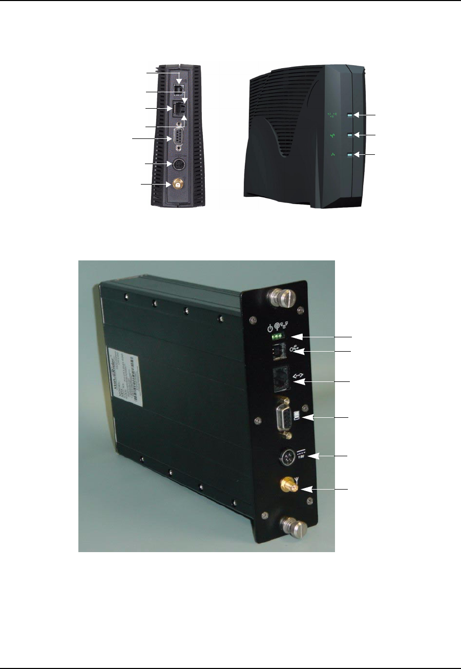
6 Installation/Diagnostic Tools
74 APCD-LM043-4.0
6.1 Indicators and Connectors
The CCU and EUM are equipped with LED indicators that provide a visual indication of the
status of the unit and its interfaces. The EUM LED indicators are illustrated in Figure 34,the
CCU LED indicators in Figure 35, and a detail view of the Ethernet connector in Figure 36.
Figure 34 EUM LEDs and Connectors
Figure 35 CCU LEDs and Connectors
The LEDs are described below:
Network LED
Radio LED
Power LED
Ethernet 10BaseT
Console Port
Power Connector
Antenna Connector
Traffic LED
Link LED
USB (not used)
LEDs (Power, Radio
and Network)
RF Connector
USB (not used)
DC Power
Connector
Console Port
Ethernet
Connector

6 Installation/Diagnostic Tools
APCD-LM043-4.0 75
6.1.1 Network LED
Table 15 Network LED
NOTE: A Network LED fast flash flashes at 2.5 Hz,50% duty cycle,
about two or three times per second.
6.1.2 Radio LED
In the following table, RSS is the Radio Signal Strength, in dBm.
Table 16 Radio LED
NOTE: ARadioLEDslow flash flashes at 0.83 Hz, 33% duty cycle, about
once per second. A Radio LED fast flash flashes at 2.5 Hz,50%
duty cycle, about two or three times per second.
6.1.3 Power LED
Table 17 Power LED
LED State Ethernet Traffic Status
OFF No Ethernet traffic present
ON Solid Ethernet traffic present but no radio traffic
Fast Flash Ethernet and radio traffic present
LED State RSS Value
OFF No radio signal present
Slow Flash Receive Threshold < RSS < -80 dBm
Fast Flash -80 dBm < RSS < -70 dBm
ON Solid RSS > -70 dBm
LED State Power Status
OFF No power
ON Power
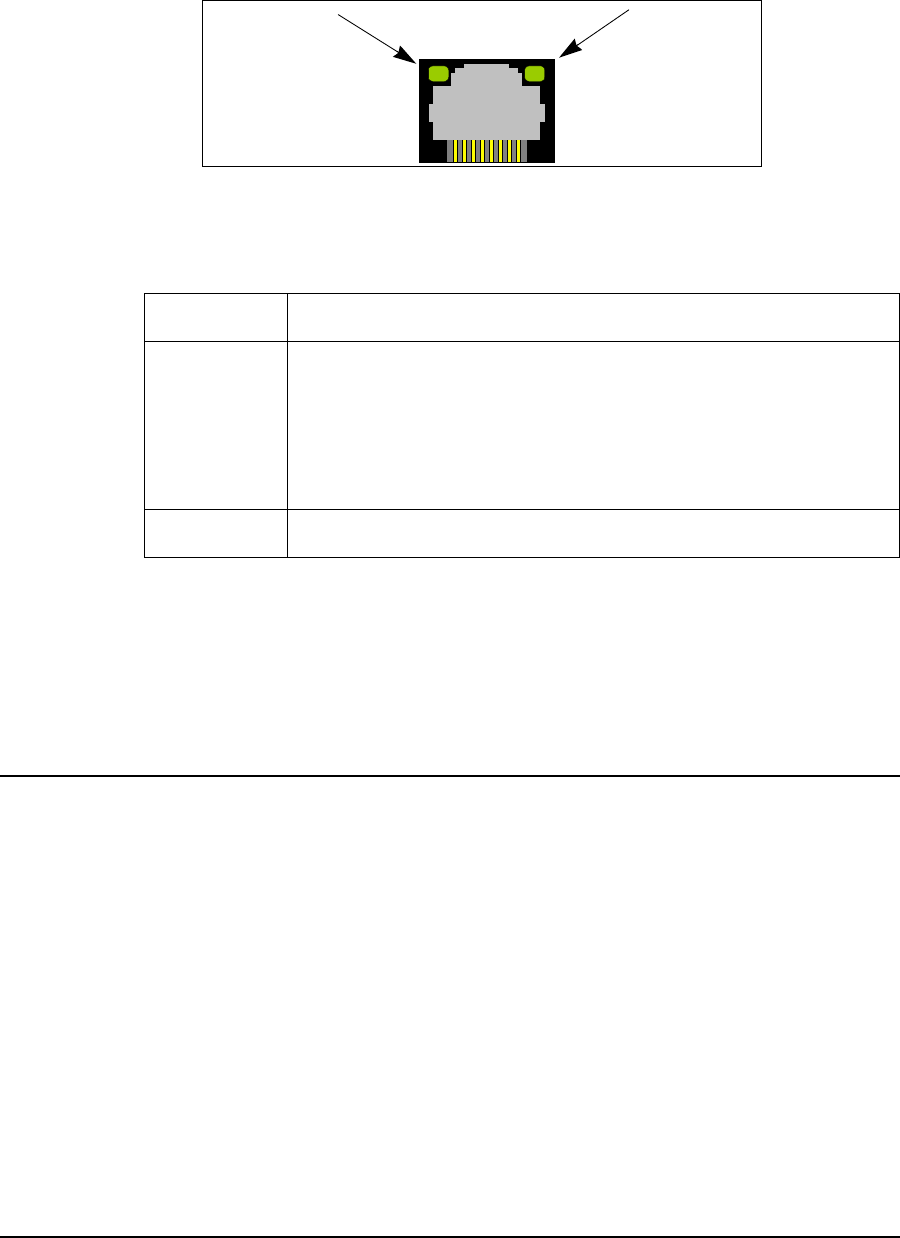
6 Installation/Diagnostic Tools
76 APCD-LM043-4.0
6.1.4 Ethernet LEDs
The Ethernet connector used in the CCU and EUM, shown in Figure 36, has two LEDs. These
LEDs are described in Table 18.
Figure 36 Ethernet LEDs
Table 18 Ethernet LEDs
The CCU is equipped with the same LEDs as the EUM but in a slightly different physical
configuration. As shown in Figure 35, the CCU indicator LEDs are closely grouped and are, in
order left to right: Power LED, Radio LED (not used on CCU), and Network LED.
6.2 Command-line Interface
The CCU and EUM are equipped with a simple command line interface through which you can
monitor unit status and configure all unit parameters. The command-line syntax is defined in
Appendix C on page 123.
The command-line interface can be accessed
• locally or remotely, using a Telnet session, or
• directly, through the DB-9 console port on the CCU and EUM, using a PC equipped
with terminal emulation software, using the console settings specified in Table 19.
LED State Ethernet Status
Link LED
If the Link LED is ON, the Ethernet physical connection is
configured and working properly. If the Link LED is OFF, then the
Ethernet physical connection is not working properly, which could
be because the wrong type of cable was used (a straight-through
cable at the EUM instead of a crossover cable) or there is a
problem with the host or device Ethernet interface.
Traffic LED The Traffic LED flashes whenever the link is transferring data.
Link LED Traffic LED

6 Installation/Diagnostic Tools
APCD-LM043-4.0 77
Table 19 Console Settings
6.3 EUM Configuration Utility
The EUM can also be configured and monitored using the EUM Configuration Utility, a
Windows-based graphical user interface (GUI) running on a PC. The PC connects to the CCU
or EUM through the DB-9 console port, the unit Ethernet port, or from anywhere in the
LMS4000 900 MHz Radio Network. The Configuration Utility and Configuration Utility User
Guide can be downloaded from the WaveRider Web site at www.waverider.com.
6.4 RSSI/Tx Quality/Antenna Pointing
The EUM Radio LED and the continuous Receive Signal Strength Indication (RSSI) reading
provide an indication of the level of the signal received from the CCU and an excellent tool for
locating and aligning the EUM antenna. Since the system is based on a polling MAC, there will
always be a signal to receive and monitor from the CCU.
The procedure for aligning the EUM antenna, which is discussed in more detail in Positioning
the Antenna on page 111, can be summarized as follows:
1. Connect the indoor antenna to the EUM and power up the EUM.
2. Once the EUM is fully booted, monitor the Radio LED while moving the antenna
around the room between suitable installation sites until you find the best signal. Use
Table 16 on page 75 as a guide.
3. If the best location produces a Fast Flash or ON Solid Radio LED, then the received
signal level is good to excellent, and this is a good location to install the antenna.
4. If the best location produces a Slow Flash Radio LED, then the received signal is
marginal. To attain the best possible signal below the Fast Flash LED level, turn on
the Continuous RSSI through the command-line interface, as follows:
Console> radio rssi
Press any key to stop
RSSI RX; TX; R1; R2; R3; F;Retry%
RSSI: 73 0; 0; 0; 0; 0; 0; 0%
Bits per second 9600
Data bits 8
Parity None
Stop bits 1
Flow Control None

6 Installation/Diagnostic Tools
78 APCD-LM043-4.0
RSSI: 73 865; 0; 0; 0; 0; 0; 0%
RSSI: 73 932; 0; 0; 0; 0; 0; 0%
RSSI: 73 933; 0; 0; 0; 0; 0; 0%
RSSI: 74 709; 0; 0; 0; 0; 0; 0%
RSSI: 73 743; 0; 0; 0; 0; 0; 0%
RSSI: 74 747; 1; 0; 0; 0; 0; 0%
Console>
Adjust the antenna location and pointing for maximum RSSI. You may need to adjust
the antenna and then step back each time to read the RSSI, so you do not obstruct
the signal from the CCU.
Note that the RSSI value is only a representation and does not give a true indication of
receive signal level. A higher RSSI value does, however, indicate a higher receive
signal level, so it can be used to indicate a best antenna placement.
To calculate the true receive signal level, use the calibration table contained in the
PCF file, described in Permanent Configuration File (CCU and EUM) on page 193.
The EUM Configuration Utility can also be used to optimize antenna pointing and
does provide a true reading of receive signal strength.
6.5 Transfer a File to or from a CCU Using FTP
You can run a simple FTP test from the EUM to verify the performance and integrity of the
communications between the CCU and EUM. The procedure outlined below will get afilefrom
the CCU (we suggest using the backup file for the CCU application, sa1110.bak), and then
(temporarily) put a file onto the CCU. In both cases, you can record the file transfer
performance. WaveRider recommends doing this procedure with a screen capture, so you
have a permanent record to baseline the performance of the link, for example.
Before you carry out the FTP test, you may want to baseline the performance of the computer
you are using at the EUM, by first connecting it directly to an FTP server and running an FTP
test back-to-back with the server. This back-to-back FTP test should be at least 3 Mbps, or
you may have a problem with your server or computer setup.
To Transfer a File to or from a CCU Using FTP
1. From the end-user computer at the EUM, bring up the Windows command line
interface.
2. At the Enter prompt, type ftp <aaa.bbb.ccc.ddd>, where <aaa.bbb.ccc.ddd> is
the CCU radio IP address.
3. In the FTP window, enter the following commands to get sa1110.bak from the CCU:
Connected to <aaa.bbb.ccc.ddd>.
220 FTP server ready
User (<aaa.bbb.ccc.ddd>:(none)): Enter <user name> or <cr> if none set
331 Password required
Password: Enter <pwd> or <cr> if none set
230 User logged in
ftp> hash

6 Installation/Diagnostic Tools
APCD-LM043-4.0 79
Hash mark printing On ftp: (2048 bytes/hash mark) .
ftp> binary
200 Type set to I, binary mode
ftp> get sa1110.bak
200 Port set okay
150 Opening BINARY mode data connection
############################################################################
###
############################################################################
###
##################################################################
226 Transfer complete
ftp: 463713 bytes received in 10.80Seconds 42.96Kbytes/sec.
ftp>bye
221 Bye...See you later.
4. Enter the following commands to put the sa1110.bak file to the CCU.
Connected to <aaa.bbb.ccc.ddd>.
220 FTP server ready
User (<aaa.bbb.ccc.ddd>:(none)):
331 Password required
Password:
230 User logged in
ftp> hash
Hash mark printing On ftp: (2048 bytes/hash mark) .
ftp> binary
200 Type set to I, binary mode
ftp> put sa1110.bak null
200 Port set okay
150 Opening BINARY mode data connection
############################################################################
####
############################################################################
####
##################################################################
226 Transfer complete
ftp: 463713 bytes sent in 8.30Seconds 55.86Kbytes/sec.
ftp>bye
221 Bye...See you later.
Entering null after the put command ensures the file will not be permanently stored to CCU
memory. If you inadvertently forget to enter null after the put command and save the file to
CCU memory, the throughput performance of the CCU may be reduced significantly. You can
remove the file using the CCU file services, available through the command line interface. As
long as you enter null after the put command, any size file can be used.
The FTP throughput should correspond to a value slightly less than the maximum allowed by
the GOS, assuming no other traffic is being carried by the CCU.
6.6 Operating Statistics
The CCU and EUM collect a wide range of IP, radio, MAC, and network layer statistics, which
can be used for measuring system performance and troubleshooting. These statistics can be
accessed through the command line interface, outlined in Appendix C on page 163 or by using
an SNMP manager. A list of available statistics and their meanings can be found in Appendix
Honpage223.

6 Installation/Diagnostic Tools
80 APCD-LM043-4.0
6.7 SNMP
The CCU and EUM are SNMP-ready. To make use of the CCU and EUM SNMP capabilities,
you must obtain the associated WaveRider MIBs from the technical support page at
www.waverider.com and install them on your SNMP manager (SNMPc, or HP OpenView, for
example).
Once you have obtained and installed these MIBs, you will, from the SNMP manager, be able
to carry out the following functions for both CCUs and EUMs:
• Read hardware and software configuration parameters, such as unit serial number,
MAC address, regulatory domain, and hardware and firmware version.
• Read operator-configurable parameters, such as IP addresses, radio frequency,
transmit power level, and the contents of the CCU Authorization and Registration
Tables.
• Read system operating statistics from the MAC layer, and the radio and Ethernet
drivers.
• Receive trap messages such as CCU or EUM power cycles.
In addition, you can program your SNMP manager to perform the following operations:
• Generate a warning or alarm whenever an operating statistic falls outside an
acceptable range.
• Perform mathematical calculations on a collection of statistics and generate a warning
or an alarm if the result of the calculation falls outside an acceptable range. This
calculation is done when a statistic, in isolation, cannot be interpreted; i.e., it can only
be interpreted properly when compared with the current value of other statistics.
• Perform a trend analysis on a statistic or group of statistics and generate a warning or
alarm when the statistic or group of statistics is starting to move towards an
unacceptable limit.
For more detailed information on how to use SNMP to monitor the performance of your
LMS4000 900 MHz Radio Network, refer to Monitoring the Network on page 127 and
Appendix G on page 199.
6.8 Field Upgrade Process
CCU and EUM operating software can be upgraded using FTP. The upgrade mechanism is
designed to be robust and reliable.
Hash codes are generated with each new software image. The new image is FTPed with the
hash code to the unit that is being upgraded, and the new software is received and written to
memory. A hash code for the new image is generated locally and compared with the hash
code that was FTPed with the new image.
If the hash code comparison is unsuccessful, the downloaded image will not be written to the
file system, and a report will be returned.

6 Installation/Diagnostic Tools
APCD-LM043-4.0 81
If the hash code comparison is successful, then the existing executable software is copied as
a backup (.bak file), and the newly downloaded image becomes the unit executable.
The unit is automatically rebooted. If the new executable is found to be corrupt for any reason,
then the unit reverts to the backed-up, older image.
6.9 FTPing CCU and EUM Configuration Files
FTP enables you to transfer configuration files to CCUs and EUMs from anywhere that has
network access to the LMS4000 900MHz Radio Network. FTP is a useful tool for the following
operations:
• Restoring a unit to an earlier working state.
• Restoring configuration files that have been corrupted.
• Configuring replacement CCUs and EUMs when units have failed.
• Changing default configurations, such as GOS.
Some of the configuration files may be the same throughout the network (port filter
configuration file, for example), and others are different for all units. Some configuration files
are loaded instantly (as soon as the file is FTPed), and some require a unit reboot to take
effect. Table 20 provides a summary of the configuration files used in the CCUs and EUMs,
whether they are typically the same throughout the system, and whether they require a unit
reboot to take effect.
Table 20 FTPing Configuration Files
NOTE: System-wide means that the configuration file in question (for
example, the port configuration file) will normally be the same
throughout your network. Configuration files, such as the route
configuration file, vary from CCU to CCU.
Configuration File File Name CCU EUM Reboot Required? System-wide?
(note 1)
GOS Configuration File gosbe.cfg
gosbronz.cfg
gossilve.cfg
gosgold.cfg
Yes No Yes
Authorization Configuration File authdb.cfg Yes No No
DHCP Configuration File dhcp.cfg Yes Yes Yes
Port Configuration File port.cfg Yes Yes Yes Yes
Route Configuration File route.cfg Yes Yes No
SNTP Configuration File port.cfg Yes Yes Yes Yes
Basic Configuration File basic.cfg Yes Yes Yes No

6 Installation/Diagnostic Tools
82 APCD-LM043-4.0
CAUTION: Use FTP to transfer configuration files between like
units only; for example, from a CCU to another CCU. (Ensure the
file is transferred using image or binary mode.) Although port
filters are used in both the CCU and EUM, there may be
differences between the port configuration file for the CCU and the
port configuration file for the EUM.
One way of using this feature is to build configuration files using a spare CCU and a spare
EUM, both of which have their RF outputs terminated in 50-ohm loads (or they could be
connected to each other through an attenuator), to ensure
• the units are not transmitting signals that could interfere with operating CCUs and
EUMs, and
• the units are not damaged by transmitting into an open circuit.
Once the CCU or EUM configuration files are built and saved in the spare units, they can be
downloaded to target CCUs and EUMs, as necessary. GOS configuration files are provided by
WaveRider.
Alternately, the configuration files could be built and saved in operating units, then
downloaded from these units to other CCUs and EUMs in the system.
FTP takes the specified configuration files from CCU or EUM memory, so changes must be
savedtoshowupinthedownloadedfiles.UsetheCLI<save> command to ensure they have
been written to the file system with the proper checksum attached.

APCD-LM043-4.0 83
7Configuring the CCU
This section explains the following procedures and topics:
•CCU and EUM Serial Number, MAC Address, and Station ID on page 84
•Setting the CCU Password on page 84
•Configuring the CCU RF Parameters on page 85
•Configuring CCU IP Parameters on page 86
•Configuring DHCP Relay on page 88
•Configuring Port Filtering on page 89
•Configuring the SNTP/UTC Time Clock on page 90
•Configuring SNMP on page 93
•Adding EUMs to the Authorization Table on page 95
Before you configure the CCU
• Familiarize yourself with the CLI commands, syntax and shortcuts, outlined in
Appendix C on page 163. This appendix provides a complete list of the available CCU
commands, some of which are not discussed in this section.
• Connect a PC to the CCU directly to the console port, or through a Telnet session.
See Command-line Interface on page 76 for console settings.
CAUTION: Remember to regularly enter save or commit and
press Enter, to save your configuration changes to the file system.
As well, some parameters and configuration files (refer to Table 20
on page 81 for details) do not take effect until you reboot the unit,
specifically the RF frequency, transmit power, and IP addressing.
CAUTION: After you have finished making your configuration
changes, remember to disconnect your terminal from the CCU.

7 Configuring the CCU
84 APCD-LM043-4.0
CAUTION: When entering IP addresses in the CCU or EUM,
note that a leading ‘0’ forces the CCU or EUM operating system to
interpret the entry as octal rather than decimal. For example,
pinging 10.0.2.010 actually pings 10.0.2.8
7.1 CCU and EUM Serial Number, MAC Address, and Station ID
The EUM/CCU product ID, serial number, station ID, and Ethernet and radio MAC addresses,
are related:
•Product ID: The product ID is the 14-character string just below the bar code on the
product label, which is affixed to the case of the unit, for example:
• EUM3000AB02A129E00A32
•Serial Number: The serial number is the last six characters of the product ID. In the
above example, the serial number is:
•E00A32
•Station (CCU or EUM) ID: The station ID is derived by prefacing the last four
characters of the serial number with ‘60’. In the above example, the station ID, in
hexadecimal notation, is:
• 60:0A:32
•Ethernet MAC Address: The Ethernet MAC address is derived by prefacing the
serial number with the characters ‘00:90:c8’. In the above example, the Ethernet MAC
address is:
• 00:90:c8:E0:0A:32
•Radio MAC Address: The radio MAC address is derived by prefacing the station ID
with the characters ‘00:90:c8’. In the above example, the radio MAC address is:
• 00:90:c8:60:0A:32
7.2 Setting the CCU Password
To Change the CCU Password
1. Type password and press Enter.
2. At the Enter Current Password prompt, type the old password.
3. At the Enter New Password prompt, type the new password.
TIP: Passwords are alphanumeric and case-sensitive. For
example, “abc” is not the same as “aBc”.

7 Configuring the CCU
APCD-LM043-4.0 85
4. At the Verify password prompt, type the new password again.
The system displays a message that your password has been successfully changed.
Example:
Console> password
Enter Current Password: ********
Enter New Password: ********
Verify password: ********
Saving new password
Password Changed
Console>
CAUTION: Remember to record the password. Unlocking the
CCU can only be performed by contacting WaveRider Technical
Support.
7.3 Configuring the CCU RF Parameters
To set the CCU Operating Frequency
1. Type radio frequency <frequency> and press Enter.
• <frequency> is the CCU operating frequency in tenths of a MHz. For example,
917.0 MHz is entered as 9170.
2. Type save or commit and press Enter.
3. Before the new radio frequency will take effect, you must reboot the CCU by typing
reset and pressing Enter.
To set the CCU Power Level
1. Type radio rf <power level> and press Enter.
• <power level> is the CCU transmit power level, either high (+26 dBm) or
low (+15 dBm). In most cases, the CCU power level should be set to high.
NOTE: Use the HIGH power level unless your site has unique
requirements for which the LOW power level is more appropriate.
2. Type save or commit and press Enter.
3. Before the new power level will take effect, you must reboot the CCU by typing reset
and pressing Enter.
Example:
The following example
• Sets the CCU operating frequency to 917 MHz,
• Sets the transmit power level to high,

7 Configuring the CCU
86 APCD-LM043-4.0
• Saves the new settings,
• Reboots the CCU so that the new parameters take effect, and
• Displays the CCU RF parameters.
Console>
Console> radio frequency 9170
Console> radio rf high
Console>
Console> save
Basic Config saved
Port Filter Config saved
sntp cfg file saved
Route Config saved
Authorization Database saved
DHCP Server Config saved
Console>
Console> reset
rebooting CCU ...
(... Power On Self Test ...)
WaveRider Communications, Inc. LMS3000
Password:
Console>
Console> radio
RF Power: HIGH
Radio Frequency: 9170
Console>
7.4 Configuring CCU IP Parameters
In IP Network Planning on page 53, you determined the following:
• CCU gateway IP address and subnet mask
• CCU radio IP address and subnet mask
• CCU Ethernet IP address and subnet mask
To set the CCU Ethernet IP address
1. Type ip ethernet <aaa.bbb.ccc.ddd> <net mask> and press Enter.
• <aaa.bbb.ccc.ddd> is the CCU Ethernet IP address.
• <net mask> is the net mask.
CAUTION: The CCU only accepts subnet masks using the
shorthand notation; for example, it accepts ‘16’, but not
‘ffff0000’or‘255.255.0.0’.
2. Type save or commit and press Enter.
3. Before the new CCU Ethernet IP address will take effect, you must reboot the CCU by
typing reset and pressing Enter.

7 Configuring the CCU
APCD-LM043-4.0 87
To set the CCU radio IP address
1. Type ip radio <aaa.bbb.ccc.ddd> <net mask> and press Enter.
• <aaa.bbb.ccc.ddd> is the CCU radio IP address.
• <net mask> is the net mask.
2. Type save or commit and press Enter.
3. Before the new CCU radio IP address will take effect, you must reboot the CCU by
typing reset and pressing Enter
NOTE: The CCU Ethernet and gateway IP addresses must be on the
same subnet, as explained in LMS4000 IP Addressing on page
53.
To set the CCU gateway IP address
1. Type ip gateway <aaa.bbb.ccc.ddd> and press Enter.
• <aaa.bbb.ccc.ddd> is the CCU gateway IP address.
2. Type save or commit and press Enter.
Example:
The following example
• Sets the CCU Ethernet IP address to 10.0.4.48 / 16,
• Sets the CCU radio IP address to 10.5.0.1 / 16,
• Sets the CCU gateway IP address to 10.0.0.1,
• Saves the new settings,
• Reboots the CCU so that the new parameters take effect, and
• Displays the CCU IP parameters.
Console>
Console> ip ethernet 10.0.4.48 16
Console> ip radio 10.5.0.1 16
Console> ip gateway 10.0.0.1
Console>
Console> save
Basic Config saved
Port Filter Config saved
sntp cfg file saved
Route Config saved
Authorization Database saved
DHCP Server Config saved
Console>
Console> reset
rebooting CCU ...
(... Power On Self Test ...)
WaveRider Communications, Inc. LMS3000
Password:
Console>
Console> ip
Ethernet IP Address: 10.0.4.48

7 Configuring the CCU
88 APCD-LM043-4.0
Ethernet Net Mask : ffff0000
Gateway IP Address: 10.0.0.1
Radio IP Address: 10.5.0.1
Radio Net Mask : ffff0000
Console>
7.5 Configuring DHCP Relay
To configure DHCP relay
• Determine the DHCP server IP address.
• Enable DHCP Relay.
• Add the DHCP server to the CCU.
To add a DHCP server
1. Type dhcp relay add <aaa.bbb.ccc.ddd> <net mask> and press Enter.
• <aaa.bbb.ccc.ddd> is the IP address of the DHCP server you want to add.
• <net mask> is the net mask of the DHCP server.
2. Repeat step 1 for any alternate DHCP servers in your network. WaveRider
recommends that your network have at least one alternate DHCP server.
3. Type save or commit and press Enter.
To enable DHCP Relay
1. Type dhcp enable and press Enter.
2. Type save or commit and press Enter.
Example:
The following example
• Enables DHCP relay,
• Adds a DHCP server with IP address 192.168.50.1 /24,
• Adds an alternate DHCP server with IP address 192.168.50.15 /24,
• Saves the new settings, and
• Displays the DHCP status.
Console> dhcp enable
Console>
Console> dhcp relay add 192.168.50.1 24
Console> dhcp relay add 192.168.50.15 24
Console>
Console> save
Basic Config saved
Port Filter Config saved
sntp cfg file saved
Route Config saved
Authorization Database saved

7 Configuring the CCU
APCD-LM043-4.0 89
DHCP Server Config saved
Console>
Console> dhcp relay
DHCP Relay Enabled:
DHCP Server Table:
DHCP Server Table:
IP Address: 192.168.50.1
Mask : ffffff00
IP Address: 192.168.50.15
Mask : ffffff00
Console>
7.6 Configuring Port Filtering
To add a port filter
• Determine the port number you want to filter.
• Determine whether you want to filter UDP, TCP, or both types of packets.
• Add the port filter to the CCU.
To add a port filter
1. Type port add <number> <type> and press Enter.
• <number> is the number of the port you want to filter.
• <type> is the type of IP packet you want to filter, either udp, tcp, or
both.
2. Repeat step 1 for any other ports that you want to filter out.
3. Type save or commit and press Enter.
Example:
The following example
• Configures the CCU to filter both UDP and TCP packets on ports 137, 138, 139 and
1512,
• Saves the new settings, and
• Displays the TCP/UDP port filters.
Console> port add 137 both
Console> port add 138 both
Console> port add 139 both
Console> port add 1512 both
Console>
Console> save
Basic Config saved
Port Filter Config saved

7 Configuring the CCU
90 APCD-LM043-4.0
sntp cfg file saved
Route Config saved
Authorization Database saved
DHCP Server Config saved
Console>
Console> port
PORT FILTERS
Port Filter
---------------------------------
137 both
138 both
139 both
1512 both
----------------------------------
Console>
NOTE: The EUM factory default settings have ports 137, 138, 139, and
1512 filtered out for both TCP and UDP, to prevent Network
Neighborhood from seeing other end users’ computers.
7.7 Configuring the SNTP/UTC Time Clock
To configure the SNTP/UTC clock
• Add an NTP server, if the one to which you want the CCU to synchronize has not
already been added. You may want to delete the default NTP servers, to force the
CCU to synchronize to the server you are adding.
• Set the SNTP client resynchronization period. The factory default setting is
3600seconds, and WaveRider recommends not changing this default setting.
• Set the SNTP client retry period. The factory default setting is 30seconds, and
WaveRider recommends not changing this default setting.
• Enable the SNTP client, to force the CCU to synchronize to an NTP server.
• Enable the SNTP relay, if you want the EUMs to be synchronized to the CCU.
To add an NTP server
1. Type time add <aaa.bbb.ccc.ddd> and press Enter.
• <aaa.bbb.ccc.ddd> is the IP address of the NTP server you are adding.
2. Type save or commit and press Enter.
CAUTION: The CCU NTP server list must always contain the
local host, which is 127.0.0.1. This entry is required for the case
where the CCU loses connectivity with the other NTP servers in
the list.
NOTE: Up to four NTP servers can be configured in the CCU, which is
shipped from the factory configured factory-default NTP servers.
To add an NTP server, you must delete one of the four defaults.

7 Configuring the CCU
APCD-LM043-4.0 91
Once again, do not delete 127.0.0.1. If you inadvertently delete it
from the list, when you use the flush command, for example, it
must be re-entered.
NOTE: It is a good idea to ping the time servers from the CCU before
adding them, to ensure you have connectivity.
To set the SNTP client resynchronization time
The SNTP client resynchronization period is the time between a successful CCU
resynchronization and the next CCU resynchronization attempt, typically set to 3600s (one
hour).
1. Type time client resync <seconds> and press Enter.
• <seconds> is the resync period in seconds.
2. Type save or commit and press Enter.
To set the SNTP client retry period
The SNTP client retry period is the time between an unsuccessful resynchronization attempt
and the next resynchronization attempt, typically set to 30 seconds.
1. Type time client retry <seconds> and press Enter.
• <seconds> is the retry period in seconds.
2. Type save or commit and press Enter.
To enable the SNTP client
1. Type time client enable and press Enter.
2. Type save or commit and press Enter.
To enable SNTP relay
1. Type time relay enable and press Enter.
2. Type save or commit and press Enter.
To display the SNTP configuration and NTP server list
•Typetime print and press Enter.
To display system time
•Typetime and press Enter.
Example:
The following example
• Flushes all existing NTP servers from the CCU,
• Adds the local host to the NTP server list (always 127.0.0.1),

7 Configuring the CCU
92 APCD-LM043-4.0
• Adds a local NTP server, IP address 10.0.0.1,
• Sets the resynchronization time to 3600 seconds,
• Sets the retry time to 30 seconds,
• Enables the SNTP client,
• Enables the SNTP relay,
• Saves the new entries,
• Displays the SNTP configuration and NTP server list, and
• Displays the system time.
Example:
Console> time flush
Console> time add 127.0.0.1
Console> time add 10.0.0.1
Console> time client resync 3600
Console> time client retry 30
Console> time client enable
Console> time relay enable
Console>
Console> save
Basic Config saved
Port Filter Config saved
sntp cfg file saved
Route Config saved
Authorization Database saved
DHCP Server Config saved
Console>
Console> time print
SNTP Client and Relay Configuration
-----------------------------------
Relay
Enabled : Yes
Destination : Default Net Broadcast. (radio IF)
Send time on...
Boot : Yes
EUM Registration : Yes
Server (send/listen)
Port : 123
Unsynchronized Stratum : 15
Synchronized Stratum : Received NTP Stratum +5
Client (fetch only)
Enabled : Yes
Port : 123
Resync period : 3600 seconds.
Retry period : 30 seconds.
NTP SERVERS
-----------------------------------
10.0.0.1
127.0.0.1
-----------------------------------
Console>
Console> time
28-FEB-2002 17:03:30
Console>

7 Configuring the CCU
APCD-LM043-4.0 93
7.8 Configuring SNMP
To fully configure SNMP
• Set the SNMP contact (name of the WISP, for example).
• Set the SNMP system location (physical location of the CCU, for example).
• Add an SNMP read community.
• Add an SNMP write community.
• Add an SNMP trap community.
To set the SNMP contact
1. Type snmp contact <contact> and press Enter.
• <contact> is text field, often used for a contact name and phone number, a
URL, or an email address, from 1-80 characters in length.
2. Type save or commit and press Enter.
To set the SNMP system location
1. Type snmp location <location> and press Enter.
• <location> is the location of the CCU, from 1-80 characters in length.
2. Type save or commit and press Enter.
To add an SNMP read community
1. Type snmp community add <community> read and press Enter.
• <community> is the name of the read community string. The default read
community string is “public”. The read community string can be from 1-32
characters in length, but spaces are not allowed.
2. Type save or commit and press Enter.
To add an SNMP write community
1. Type snmp community add <community> write and press Enter.
• <community> is the name of the write community string. The default write
community string is “private”. The write community string can be from 1-32
characters in length, but spaces are not allowed.
2. Type save or commit and press Enter.
To add an SNMP trap server
1. Type snmp trap add <aaa.bbb.ccc.ddd> <community> and press Enter.
• <aaa.bbb.ccc.ddd> is the IP address of the trap server
• <community> is the name of the community on the trap server, from 1-64
characters in length.
2. Type save or commit and press Enter.

7 Configuring the CCU
94 APCD-LM043-4.0
Example:
The following example
• Sets the SNMP contact as WaveRider,
• Sets the SNMP location as Calgary_South,
• Adds SNMP read community WaveRider_Calgary,
• Adds SNMP write community WaveRider_Calgary,
•AddsSNMPtrapserverWaveRider_Calgary, IP address 10.0.1.68,
• Saves the new settings, and
• Displays the SNMP settings.
Example:
Console>
Console> snmp contact WaveRider
Console> snmp location Calgary_South
Console> snmp community add WaveRider_Calgary read
Console> snmp community add WaveRider_Calgary write
Console> snmp trap add 10.0.1.68 WaveRider_Calgary
Console>
Console> save
Basic Config saved
Port Filter Config saved
sntp cfg file saved
Route Config saved
Authorization Database saved
DHCP Server Config saved
Console>
Console> snmp
Contact: WaveRider
Location: Calgary_South
Name: LMS3000
SNMP Read Communities:
WaveRider_Calgary
SNMP Write Communities:
WaveRider_Calgary
SNMP Traps:
10.0.1.68 WaveRider_Calgary
Console>

7 Configuring the CCU
APCD-LM043-4.0 95
7.9 Adding EUMs to the Authorization Table
To add EUMs on the system, enter them in the CCU Authorization Table.
To add an EUM to the CCU Authorization Table
1. Type auth add <eum id> <gos> and press Enter.
• <eum id> is the hexadecimal representation of the EUM ID
• <gos> is the grade of service that you want to assign to the EUM, one of:
• be (best effort),
• bronze,
•silver,
• gold, or
• denied.
2. Type save or commit and press Enter.
The following example
•AddsEUMID60:0a:32 to the Authorization Table, and assigns it the silver grade
of service,
• Saves the new settings, and
• Displays the Authorization Table.
Console>
Console> auth add 60:0a:32 silver
Console>
Console> save
Basic Config saved
Port Filter Config saved
sntp cfg file saved
Route Config saved
Authorization Database saved
DHCP Server Config saved
Console>
Console> auth
EUM ID GOS CLASS
----------------------
60:0a:32 silver
Default be
Total of 1 entries
Console>
—This page is intentionally left blank —
APCD-LM043-4.0 97
8Configuring the EUM
This chapter covers the following procedures:
•Setting the EUM Password on page 98
•Configuring the EUM RF Parameters on page 98
•Configuring EUM IP Parameters on page 99
•Configuring Port Filtering on page 101
•Configuring SNMP on page 102
•Configuring the Customer List on page 104
Before you configure the EUM
• Familiarize yourself with the CLI commands, syntax and shortcuts, outlined in
Appendix C on page 163.Command-line Syntax provides a complete list of the
available EUM commands, some of which are not discussed in this section.
• Connect a PC directly to the EUM console port, or through a Telnet session. See
Command-line Interface on page 76 for console settings.
CAUTION: Remember to regularly enter save or commit and
press Enter, to save your configuration changes to memory. As
well, some parameters will not take effect until you reboot the unit,
specifically the RF frequency, transmit power and IP addressing.
CAUTION: After you have finished making your configuration
changes, remember to disconnect your PC from the EUM console
port
CAUTION: When entering IP addresses in the CCU or EUM,
note that a leading ‘0’ forces the CCU/EUM operating system to
interpret the entry as octal rather than decimal. For example,
pinging 10.0.2.010 actually pings 10.0.2.8
8 Configuring the EUM
98 APCD-LM043-4.0
8.1 Setting the EUM Password
To Change the EUM Password
1. Type password and press Enter.
2. At the Enter Current Password prompt, type the old password.
3. At the Enter New Password prompt, type the new password.
TIP: Passwords are alphanumeric and case-sensitive. For
example, “abc” is not the same as “aBc”.
4. At the Verify password prompt, type the new password again.
The system displays a message that your password has been successfully changed.
Example:
Console> password
Enter Current Password: ********
Enter New Password: ********
Verify password: ********
Saving new password
Password Changed
Console>
CAUTION: Remember to record the password. Unlocking the
EUM can only be performed by contacting WaveRider Technical
Support.
8.2 Configuring the EUM RF Parameters
To set the EUM Operating Frequency
1. Type radio frequency <frequency> and press Enter.
• <frequency> is the EUM operating frequency in tenths of a MHz. For
example, 917.0 MHz is entered as 9170.
2. Type save or commit and press Enter.
3. Before the new radio frequency will take effect, you must reboot the EUM by typing
reset and pressing Enter.
To set the EUM Power Level
1. Type radio rf <power level> and press Enter.
• <power level> is the EUM transmit power level, either high (+26 dBm) or
low (+15 dBm). In most cases, the EUM power level should be set to high.

8 Configuring the EUM
APCD-LM043-4.0 99
2. Type save or commit and press Enter.
3. Before the new power level will take effect, you must reboot the EUM by typing reset
and pressing Enter.
Example:
The following example
• Sets the EUM operating frequency to 917 MHz,
• Sets the transmit power level to high,
• Saves the new settings,
• Reboots the EUM so that they new parameters take effect, and
• Displays the EUM RF parameters.
Console>
Console> radio frequency 9170
Console> radio rf high
Console>
Console> save
Basic Config saved
Port Filter Config saved
sntp cfg file saved
Console>
Console> reset
rebooting EUM ...
(... Power On Self Test ...)
WaveRider Communications, Inc. LMS3000
Password:
Console>
Console> radio
RF Power: HIGH
Radio Frequency: 9170
Console>
8.3 Configuring EUM IP Parameters
In IP Network Planning on page 53, you determined the following:
• CCU radio IP address and subnet mask
• EUM Ethernet IP address and subnet mask
• End-user PC Ethernet IP address and subnet mask
To set the EUM Ethernet IP address
1. Type ip ethernet <aaa.bbb.ccc.ddd> <net mask> and press Enter.
• <aaa.bbb.ccc.ddd> is the CCU Ethernet IP address.
• <net mask> is the net mask.

8 Configuring the EUM
100 APCD-LM043-4.0
CAUTION: The EUM only accepts subnet masks using the
shorthand notation; for example, it accepts ‘16’, but not
‘ffff0000’or‘255.255.0.0’.
2. Type save or commit and press Enter.
3. Before the new EUM Ethernet IP address will take effect, you must reboot the EUM by
typing reset and pressing Enter.
To set the EUM gateway IP address
1. The EUM gateway is the CCU radio, so the EUM gateway IP address is the CCU
radio IP address.
2. Type ip gateway <aaa.bbb.ccc.ddd> and press Enter.
• <aaa.bbb.ccc.ddd> is the CCU radio IP address.
3. Type save or commit and press Enter.
4. Before the new EUM gateway IP address will take effect, you must reboot the EUM by
typing reset and pressing Enter.
Example:
The following example
• Sets the EUM Ethernet IP address to 10.0.4.48 / 16,
• Sets the EUM gateway IP address to 10.5.0.1,
• Saves the new settings,
• Reboots the EUM so that the new parameters take effect, and
• Displays the EUM IP parameters.
Console>
Console> ip ethernet 10.0.4.48 16
Console> ip gateway 10.0.0.1
Console>
Console> save
Basic Config saved
Port Filter Config saved
sntp cfg file saved
Console>
Console> reset
rebooting EUM ...
(... Power On Self Test ...)
WaveRider Communications, Inc. LMS3000
Password:
Console> ip
Ethernet IP Address: 10.0.4.48
Ethernet Net Mask : ffff0000
Gateway IP Address: 10.0.0.1
Radio IP Address: 10.5.0.1
Radio Net Mask : ffff0000
Console>

8 Configuring the EUM
APCD-LM043-4.0 101
8.4 Configuring Port Filtering
To add a port filter:
• Determine the port number you want to filter.
• Determine whether you want to filter UDP, TCP, or both types of packets.
• Add the port filter to the EUM.
To add a port filter
1. Type port add <number> <type> and press Enter.
• <number> is the number of the port you want to filter.
• <type> is the type of IP packet you want to filter, either udp, tcp, or
both.
2. Type save or commit and press Enter.
Example:
The following example
• Configures the EUM to filter both UDP and TCP packets on ports 137, 138, 139 and
1512,
• Saves the new settings, and
• Displays the TCP/UDP port filters.
Console> port add 137 both
Console> port add 138 both
Console> port add 139 both
Console> port add 1512 both
Console>
Console> save
Basic Config saved
Port Filter Config saved
sntp cfg file saved
Console>
Console> port
PORT FILTERS
Port Filter
---------------------------------
137 both
138 both
139 both
1512 both
----------------------------------
Console>

8 Configuring the EUM
102 APCD-LM043-4.0
8.5 Configuring SNMP
To fully configure SNMP
• Set the SNMP contact (name of the WISP, for example).
• Set the SNMP system location (physical location of the EUM, for example).
• Add an SNMP read community.
• Add an SNMP write community.
• Add an SNMP trap server.
To set the SNMP contact
1. Type snmp contact <contact> and press Enter.
• <contact> is a name and phone number, a URL, or an email address, from 1-
80 characters in length.
2. Type save or commit and press Enter.
To set the SNMP system location
1. Type snmp location <location> and press Enter.
• <location> is the location of the EUM, from 1-80 characters in length.
2. Type save or commit and press Enter.
To add an SNMP read community
1. Type snmp community add <community> read and press Enter.
• <community> is the name of the read community string. The default read
community string is “public”. The read community string can be from 1-32
characters in length, but spaces are not allowed.
2. Type save or commit and press Enter.
To add an SNMP write community
1. Type snmp community add <community> write and press Enter.
• <community> is the name of the write community string. The default write
community string is “private”. The write community string can be from 1-32
characters in length, but spaces are not allowed.
2. Type save or commit and press Enter.
To add an SNMP trap server
1. Type snmp trap add <aaa.bbb.ccc.ddd> <community> and press Enter.
• <aaa.bbb.ccc.ddd> is the IP address of the trap server
• <community> is the name of the community on the trap server, from 1-64
characters in length.
2. Type save or commit and press Enter.

8 Configuring the EUM
APCD-LM043-4.0 103
Example:
The following example
• Sets the SNMP contact as WaveRider,
• Sets the SNMP location as Calgary_South,
• Adds the SNMP read community WaveRider_Calgary,
• Adds the SNMP write community WaveRider_Calgary,
• Adds the SNMP trap server WaveRider_Calgary, IP address 10.0.1.68,
• Saves the new settings, and
• Displays the SNMP settings.
Example:
Console>
Console> snmp contact WaveRider
Console> snmp location Calgary_South
Console> snmp community add WaveRider_Calgary read
Console> snmp community add WaveRider_Calgary write
Console> snmp trap add 10.0.1.68 WaveRider_Calgary
Console>
Console> save
Basic Config saved
Port Filter Config saved
sntp cfg file saved
Console>
Console> snmp
Contact: WaveRider
Location: Calgary_South
Name: LMS3000
SNMP Read Communities:
WaveRider_Calgary
SNMP Write Communities:
WaveRider_Calgary
SNMP Traps:
10.0.1.68 WaveRider_Calgary
Console>

8 Configuring the EUM
104 APCD-LM043-4.0
8.6 Configuring the Customer List
You can set the maximum number of customers or PCs (customer_max) that can concurrently
access the radio link through the EUM, as described in Customer Table (EUM only) on page
192.
CAUTION: The simulation data presented in Performance
Modelling on page 42 is based on one end user (one PC) per
EUM. If customer_max is set to a value greater than ‘1’, and there
is more than one end user per EUM, the throughput performance
of the radio link will be affected.
TIP: When you are locally troubleshooting the EUM installation, if
customer_max is set to ‘1’ and you want to substitute and use a
known-working PC in place of the end-user’s PC, you will have to
reset the EUM or wait for the Customer Table to time out.
To set customer_max
1. Type cust max <value> and press Enter.
• <value> is the maximum number of customers (PCs), from 1-50.
2. Type save or commit and press Enter.
Example:
The following example
•Setscustomer_max to 3,
• Saves the new setting, and
• Displays the value of customer_max.
Console>
Console> cust max 3
Maximum customers: 3
Console>
Console> save
Basic Config saved
Port Filter Config saved
sntp cfg file saved
Console>
Console> cust max
Maximum customers: 3
Console>
Console>

APCD-LM043-4.0 105
9Installing the EUM
9.1 Before you Start the EUM Installation
Before you start the EUM installation, ensure the following points have been addressed:
• The EUM has been configured with at least the following settings:
• IP address
• Subnet mask
• Gateway IP address
• Radio frequency
• The CCU network is installed and verified.
• DHCP relay is enabled at the CCU, with network access to a valid DHCP server.
• The end-user PC is equipped with an Ethernet interface card, and is configured to
obtain its IP address remotely, using DHCP.
• The installer knows the direction from the EUM to the CCU (WISP radio site).
• The installer has read this chapter.
• The installer knows the EUM IP address.
• The WISP has authorized the EUM at the CCU (or no communications will be
possible).
Procedures are provided below for addressing situations where some of the above items
could not be taken care of prior to the EUM installation.

9 Installing the EUM
106 APCD-LM043-4.0
9.2 Other EUM Programming Considerations
Although the IP settings identified above are required for basic EUM operation, you should
also consider pre-configuring the following EUM parameters:
SNMP
SNMP communities can be configured in the EUM to enable remote monitoring of the EUM
using an SNMP manager. Refer to Configuring SNMP on page 102.
Customer List
The factory default configuration allows only one PC to be logically connected to the EUM at
any given time. If you want to use a separate PC as an aid to installing and confirming the
EUM link prior to connecting the end-user PC, then you will have to reset the EUM when
changing between the end-user PC and the installation test PC.
Port Filtering
Port filtering is set in the EUM to filter out Network Neighborhood. You can edit Port filtering in
theEUM,ifdesired.RefertoConfiguring Port Filtering on page 101.
Output Power
In most cases, the EUM output power should be set to HIGH.
9.3 Installation Overview
Installing the EUM involves the following procedures:
1. Opening the Box on page 107
2. Turning off the End-user’s Cordless Phones on page 108
3. Choosing a Location for the EUM and Antenna on page 108
4. Connecting the EUM Components on page 108
5. Conducting a Preliminary Check of the EUM on page 110
6. Positioning the Antenna on page 111
7. Mounting the Antenna on page 112
8. Connecting the End-user’s PC on page 115
9. Obtaining Valid IP Addresses for the End-user’s PC on page 116
10. Testing the Data Link on page 116
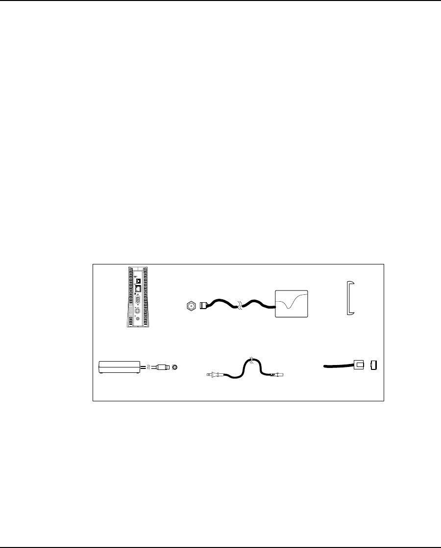
9 Installing the EUM
APCD-LM043-4.0 107
11. Configuring the Browser Application on page 119
12. Completing the Installation on page 120
13. Baselining the Installation on page 120
9.4 Installation Procedures
9.4.1 Opening the Box
Before you install the EUM components, verify that the EUM kit is complete.
EUM Kit Components
• EUM modem
• AC/DC power supply with 2-meter DC power cable
• 2-meter AC power cable
• Crossover Ethernet cable
Antenna Kit Components
• Indoor antenna with attached 3-meter cable
• Flush-mountable antenna bracket
• Two antenna-mount suction cups, two drywall plugs, and two screws
Refer to Figure 37 for an illustration of each EUM component.
Figure 37 EUM Components
NOTE: The antenna-mount suction cups, drywall plugs, and screws are
not shown in Figure 37.
EUM
Ethernet
Cable
Antenna
Bracket
Antenna with attached cable
AC Power Cable
AC/DC adapter with
C power cable attached

9 Installing the EUM
108 APCD-LM043-4.0
9.4.2 Turning off the End-user’s Cordless Phones
Turn off all cordless phones in the customer’s premises, and any other equipment that uses
the 900MHz ISM band. Once the installation is complete, turn this equipment back on.
9.4.3 Choosing a Location for the EUM and Antenna
The location of the antenna has a significant effect on the performance of the EUM installation.
Before you connect the EUM components, follow the guidelines provided below for choosing
the best location for the antenna and the EUM.
Choosing the Best Location for the EUM
ThebestlocationfortheEUMis
• indoors,
• upright,
• on a stable, flat surface, and
• in a position where its air vents are unobstructed.
NOTE: Avoid placing the EUM in direct sunlight or near other sources of
heat (such as an electric heater).
Choosing the Best Location for the Antenna
The best location for the antenna is
• indoors,
• near an outside entrance or window, preferably in the location with the best
possible path to the CCU, and
• a minimum of 20cm (8in.) from personnel.
9.4.4 Connecting the EUM Components
Now that you have chosen a suitable location, use the instructions in this section for
connecting the following components to the EUM, in the order shown in Figure 38:
• Antenna
• EUM AC/DC adaptor (DC cable first, then AC cable)
9 Installing the EUM
APCD-LM043-4.0 109
When you have completed the above tasks, connect the EUM AC/DC adaptor to an AC power
bar or outlet.
Figure 38 Connecting the EUM Components
To Connect the EUM Components
1. Finger-tighten the antenna cable onto the corresponding connector at the back of the
EUM (refer to Step 1 in Figure 38). Do not use wrenches or pliers. Do not cross-thread
or over tighten.
WARNING!
You must connect the antenna to the modem before
operating the system. Failure to do so may result in
permanent equipment damage.
2. Connect the AC/DC adaptor to the EUM. To do this, line up the guides in the DC
power cord connector with the notches in the power plug on the EUM and press the
connector firmly into place (refer to Figure 39).
Figure 39 Connect the DC Power Cord to the EUM
Denotes reserved ports. Do NOT Connect.
2
AC/DC Adapter
Pow er Bar
EUM
Step 1
Antenna Cable
Step 3
AC Cable Step 2
DC Cable
Antenna
Bracket
Antenna
Connector
DC Power
Connector
Ethernet
Connector
1
Press firmly at the base of
the DC connector
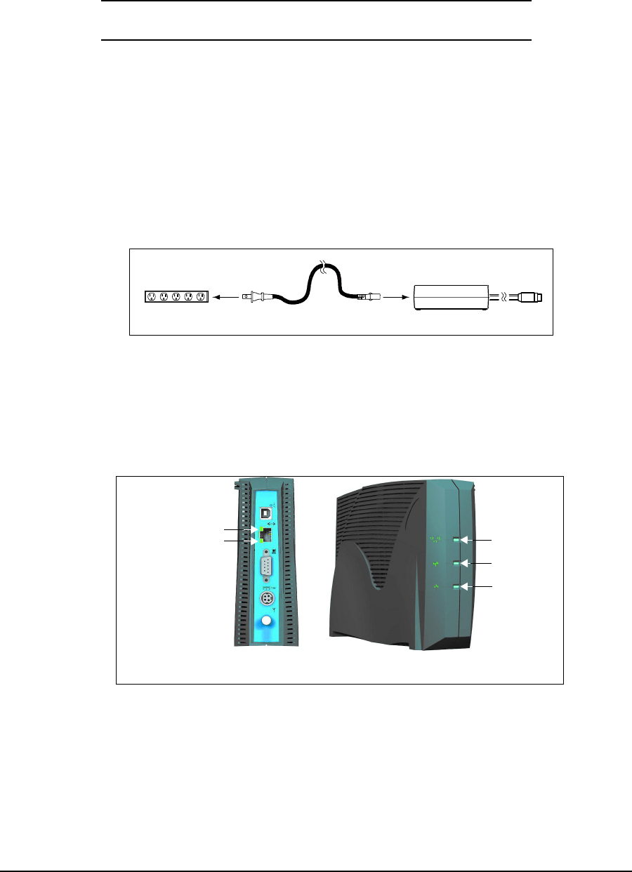
9 Installing the EUM
110 APCD-LM043-4.0
NOTE: The DC power cable features a secure locking connector. To
disconnect the cable, pull the collar back on the connector, then
continue pulling to detach the DC power cable from the EUM.
3. Connect the AC power cord between the AC/DC adaptor and either an AC power bar
(preferred) or AC outlet (Figure 40). The EUM immediately powers up since it does
not have an ON/OFF switch.
NOTE: To avoid potential damage to the EUM components in the event
of a power surge, WaveRider recommends using a power bar
with surge protection (instead of connecting the AC power cord
directly to an AC outlet).
Figure 40 Connect the AC Power Cord
9.4.5 Conducting a Preliminary Check of the EUM
Check the LED indicators on the front of the modem to ensure that the EUM is functioning
properly.
Figure 41 EUM LEDs
To Verify Proper EUM Function
• Check that the Power LED is ON. It takes about 7 or 8 seconds to come on after you
have plugged in the unit.
The EUM uses a custom antenna cable and connector. If you
need to extend this cable, contact WaveRider.
Power Bar AC Power Cable AC/DC Adaptor
Network LED
Radio LED
Power LED
Ethernet Link LED
Ethernet Traffic LED
Back Panel Front Panel
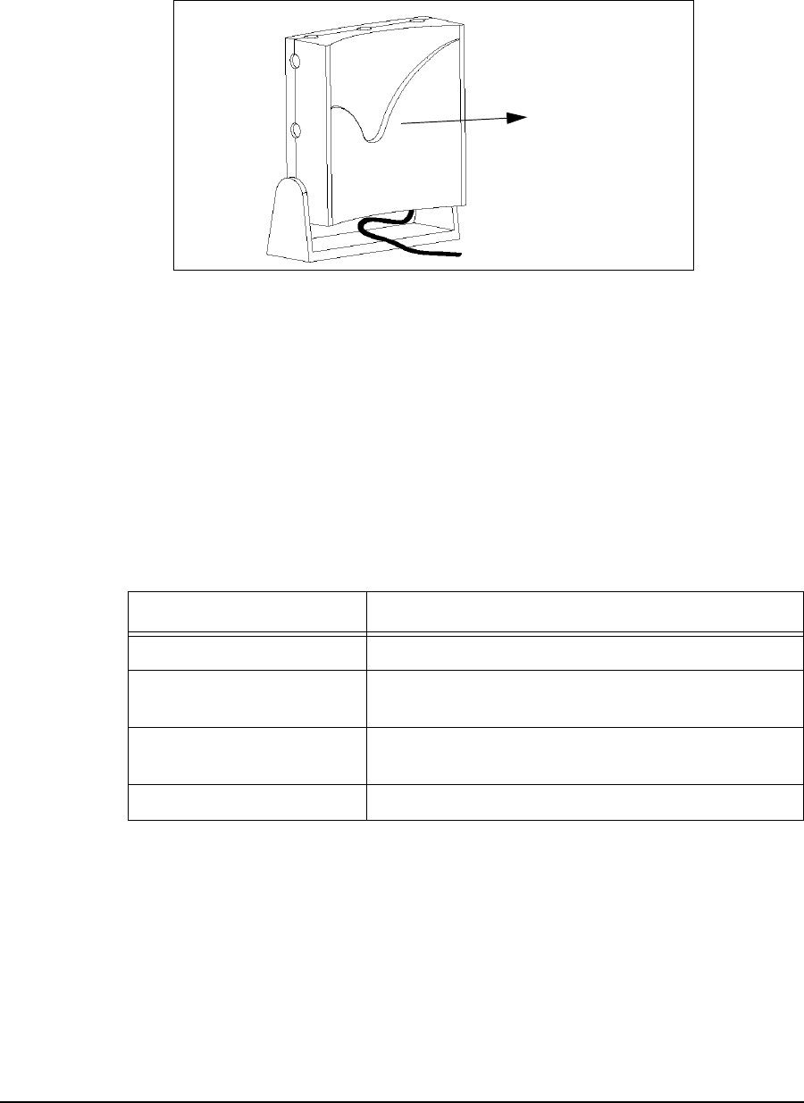
9 Installing the EUM
APCD-LM043-4.0 111
9.4.6 Positioning the Antenna
1. To begin with, point the antenna in the general direction of the CCU, as shown in
Figure 42:
Figure 42 Preliminary Orientation of the Antenna (Top View)
As illustrated, for maximum signal reception, point the concave surface of the antenna
toward the CCU, and ensure your body (including fingers) are not between the
antenna and the CCU.
2. Monitor the Radio LED, shown in Figure41onpage110and refer to Table 21.Move
the antenna until the Radio LED is flashing quickly, or is ON solidly, indicating that you
have a good to very-good radio signal. After each repositioning or reorientation of the
antenna, you may have to step back from the antenna so that you are not interfering
with the received signal.
Table 21 Radio LED Status Displays
3. If the Radio LED is off or flashes slowly, then the antenna should be moved to a better
location. Keep in mind that the antenna and EUM do not have to be located in the
same room as the end-user’s PC since up to 100m (300ft.) of CAT5 data cable can
connect the EUM to the PC.
4. If you cannot find an indoor antenna location that provides a solid ON or fast-flashing
LED, refer to Troubleshooting on page 121.
5. Once you have found a good location, you are ready to mount the antenna, as
described in section 9.4.7, Mounting the Antenna.
Radio LED Display Status
Off No radio signal present.
Slow Flash ON/OFF 1.25 times per second. The signal strength
is poor to marginal.
Fast Flash ON/OFF 2.5 times per second. The signal strength is
good.
Solid On The signal strength is very good.
To Base Station
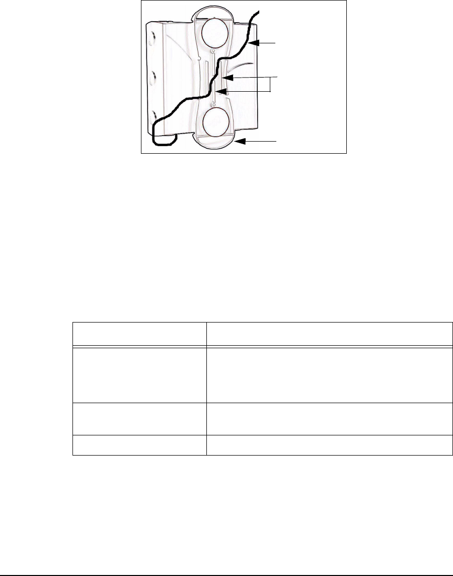
9 Installing the EUM
112 APCD-LM043-4.0
9.4.7 Mounting the Antenna
The antenna bracket is designed to accommodate the RF cable and act as a strain relief.
To Mount the Antenna
1. Thread the attached antenna cable through the guides in the back of the antenna
bracket, as necessary.
Figure 43 Rear View of Antenna Bracket
NOTE: Bending the antenna cable too sharply can degrade EUM
performance. Never allow less than a 1.25 cm (0.5 in.) bend
radius. If a quarter (25-cent piece) fits into the curve, the bend is
acceptable.
The EUM kit includes suction cups, drywall plugs, and screws to allow a variety of
mounting options:
Table 22 Antenna Mount Guidelines
2. Insert the suction cups or screws into the base of the antenna bracket, then mount the
bracket onto the desired surface.
NOTE: If you mount your antenna bracket on a vertical surface, orient
the bracket so that the spring clip is closest to the ceiling.
Mounting Method Guidelines
Suction Cups Use on flat, smooth surfaces, such as glass, plastic,
laminates or metal. Remove all grease, oil, and grit
before securing the antenna bracket with suction
cups.
Drywall Plugs Use on all commercial drywall and other plaster
surfaces.
Screws Use on hardwood surfaces.
Antenna Bracket
Bracket Guides
Antenna Cable
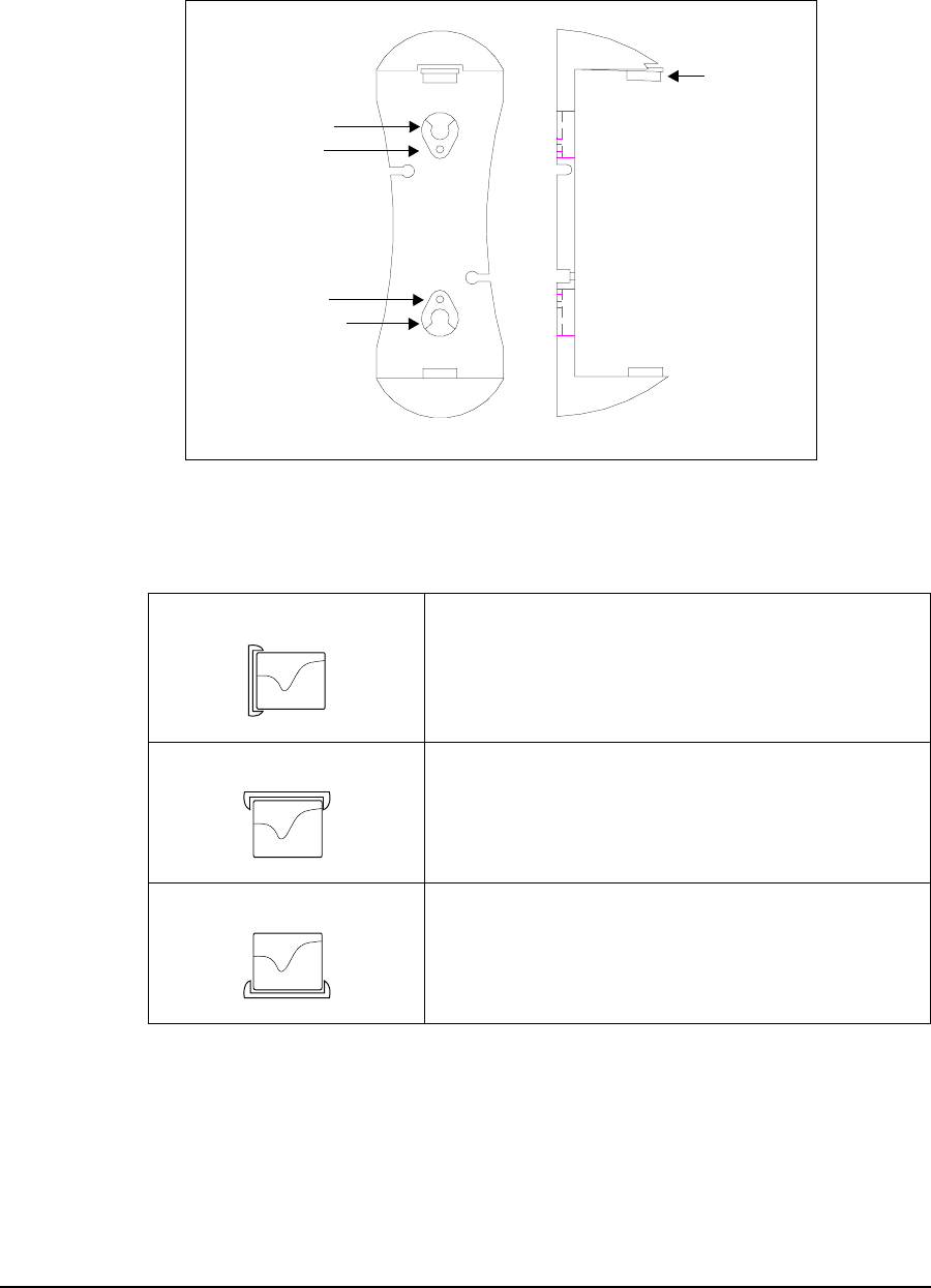
9 Installing the EUM
APCD-LM043-4.0 113
Figure 44 shows the location of the spring clip, suction cup holes, and screw holes on
the antenna bracket.
Figure 44 Antenna Bracket Components
Table 23 Surface Mounting Options for the Antenna
Side Mount Mount the antenna on a wall, window, window frame,
or solid furniture with spring clip side closest to the
ceiling.
Top Mount
Hang the antenna from a ceiling or the shelf of a
bookcase.
Bottom Mount
Mount the antenna on solid furniture (a desk or shelf)
or on a window sill.
Spring Clip
Suction Cup Hole
Screw Hole
Suction Cup Hole
Screw Hole
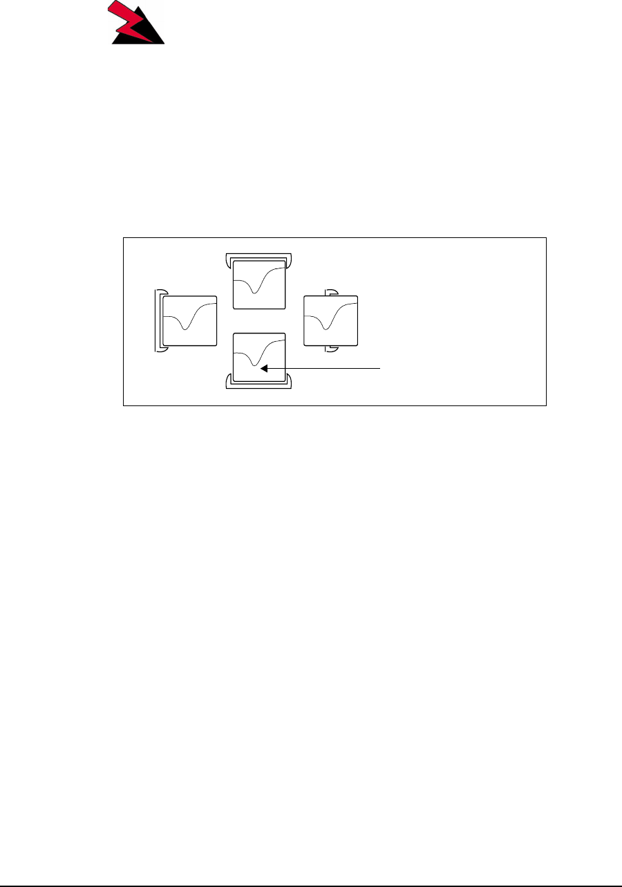
9 Installing the EUM
114 APCD-LM043-4.0
WARNING!
The antennas for the EUM must be fix-mounted, indoors or
outdoors, to provide a separation distance of 20cm or more
from all persons, to satisfy RF exposure requirements. The
distance is measured from the front of the antenna to the
human body. WaveRider recommends installing the
antenna in a location where personnel are not able to bump
into it, obstruct the signal from the base station, or trip over
antenna cables.
3. Position the antenna in the bracket according to one of the configurations illustrated in
Figure 45. Click and lock the antenna in place. For maximum signal reception, ensure
the concave surface of the antenna points toward the WISP antenna and the trough of
the inset wave points towards the floor.
Figure 45 Mounting the Antenna in the Bracket
NOTE: The location, position, and orientation of the antenna affects the
robustness of the Internet connection. Pointing the antenna at
buildings or other obstacles often impedes communications, but
some surfaces may provide desirable signal bounce. For optimal
reception, try various positions before fix-mounting your antenna.
4. Once the antenna is permanently mounted, re-align it for best signal.
- Concave surface pointing
towards WISP antenna
- Trough of inset wave pointing
towards floor.
Inset wave

9 Installing the EUM
APCD-LM043-4.0 115
9.4.8 Connecting the End-user’s PC
1. Connect the end-user’s PC, shown in Figure 46, by attaching the crossover Ethernet
cable that is included with the kit between the Ethernet port on the end-user’s
computer and the Ethernet port on the EUM.
Figure 46 Connecting the End-user’s PC
2. Check the Ethernet LEDs on the back panel of the EUM to ensure the Ethernet
connection between the EUM and the end-user’s PC is active. Refer to Table 24 for an
explanation of the Ethernet LED status displays.
Table 24 Ethernet LED Status Displays
3. When attempting to send data to, or receive data from, the Internet, check the
Ethernet Traffic LED to ensure data transmission is taking place. This LED flashes as
data traffic passes between the end-user’s PC and the EUM. The network LED on the
front of the EUM also flashes and is more accessible than the Traffic LED on the rear
of the EUM.
Ethernet LED Status
Ethernet Link LED This LED is lit when there is a correct connection to
the computer, and both ends are powered ON.
Ethernet Traffic LED Flashes when data passes through the Ethernet
connection in either direction.
Denotes reserved ports. Do NOT Connect.
omputer
2
AC/DC Adapter
Pow er Bar
EUM
Step 1
Antenna Cable
Step 4
Ethernet Cable
Step 3
AC Cable Step 2
DC Cable
Antenna
Bracket
Antenna
Connector
DC Power
Connector
Ethernet
Connector
4
4
1

9 Installing the EUM
116 APCD-LM043-4.0
9.4.9 Obtaining Valid IP Addresses for the End-user’s PC
1. To obtain IP addresses for the end-user’s PC, including the PC IP address, Gateway
IP address, and DNS server address, the PC must request an update from the DHCP
server. This procedure varies depending on which version of Windows operating
system is running on the end-user’s PC, but a general method is outlined as follows:
For Windows 95, 98:
• Using Windows utility winipcfg, select Start >Run,type<winipcfg> in
the command line, and press Enter.
•Fromthewinipcfg menu, select Release All,thenRenew All.
• Using DOS, select Start >Run,typecmd or command (the exact process
may vary, so consult your operating system manual)
•Usingthe<ipconfig> command set, Renew all adaptors.
2. If no error messages are returned, the WISP network has successfully provided an IP
address to the end-user’s PC. You can confirm the success by checking the assigned
IP addresses. If the assigned Gateway IP address corresponds to the EUM Gateway
IP address, then the operation was successful.
3. If a valid IP address cannot be achieved, see Troubleshooting on page 121.
9.4.10 Testing the Data Link
The fact that the IP address was successfully obtained indicates that the data link from the PC
to the WISP's network is functioning properly. WaveRider recommends more thorough testing
of the EUM-to-CCU data link, as outlined below. These tests can also be used to troubleshoot
simple problems if DHCP access is not available.
There are several tools available for testing the quality of the link between the end-user PC
and the WISP network. The most important tool is the ping utility, which is available in the
CCU, EUM, and the end-user PC. The ping command can be used to progressively test the
data link, as follows:
•To Test the Data Link from the End-user’s PC to the EUM, on page 116
•Testing the Data Link from the End-user’s PC to the Network, on page 118
•Testing the Data Link from the End-user’s PC to the Internet, on page 119
To Test the Data Link from the End-user’s PC to the EUM
1. Ping the EUM’s IP address from the end-user’s PC, as follows:
• Open a DOS window in the end-user’s PC.
• At the command prompt, type ping <aaa.bbb.ccc.ddd>, where
<aaa.bbb.ccc.ddd> is the IP address of the EUM and press Enter.
2. If there is no response, check the following:
• PC IP address settings.
• Ethernet crossover cable between the EUM and the end-user’s PC, to ensure
that the pins have not been damaged and that the pin-outs are consistent with
those shown in General Troubleshooting Information,onpage151.
3. If there is a response, but with errors, check the Ethernet crossover cable.
9 Installing the EUM
APCD-LM043-4.0 117
To illustrate data link testing between the PC and the EUM, consider the sample configuration
shown in Figure 47.
Figure 47 Sample Configuration — Testing the Data Link
Using the sample configuration shown in Figure 47, confirm the connection between the end-
user’s PC and the EUM as demonstrated below:
This is what successful ping from the end-user’s PC to the EUM looks like:
C:\>ping 10.5.4.117
Pinging 10.5.4.117 with 32 bytes of data:
Reply from 10.5.4.117: bytes=32 time<10ms TTL=64
Reply from 10.5.4.117: bytes=32 time<10ms TTL=64
Reply from 10.5.4.117: bytes=32 time<10ms TTL=64
Reply from 10.5.4.117: bytes=32 time<10ms TTL=64
Ping statistics for 10.5.4.117:
Packets: Sent = 4, Received = 4, Lost = 0 (0% loss),
Approximate round trip times in milli-seconds:
Minimum = 0ms, Maximum = 0ms, Average = 0ms
C:\>
This is what an unsuccessful ping from the end-user’s PC to the EUM looks like:
C:\>ping 10.5.4.116
Pinging 10.5.4.116 with 32 bytes of data:
Request timed out.
Request timed out.
Request timed out.
Request timed out.
Ethernet crossover
cable
EUM Antenna
Gateway Router
Internet
Radio
Link
End-user's Premises
End-user's PC
IP Address 10.5.6.117
Net Mask 16
Gateway IP 10.5.0.1
EUM3000
IP Address 10.5.4.117
Net Mask 16
Gateway IP 10.5.0.1
CCU3000
Radio IP Address 10.5.0.1
Net Mask 16

9 Installing the EUM
118 APCD-LM043-4.0
Ping statistics for 10.5.4.116:
Packets: Sent = 4, Received = 0, Lost = 4 (100% loss),
Approximate round trip times in milli-seconds:
Minimum = 0ms, Maximum = 0ms, Average = 0ms
C:\>
Ifyouarenotableto<ping> the EUM from the PC, go to Troubleshooting on page 121.
Testing the Data Link from the End-user’s PC to the Network
Once the connection from the PC to the EUM is confirmed, ping the EUM gateway address
from a PC DOS window. Ping with short packets first to confirm function, and then with long
packets (1472 byte packets) to confirm performance. Errors observed on pings with long
packets indicate a high error rate on the channel, caused by low signal levels or interference.
To Ping a CCU with the maximum packet size
1. Open a DOS window.
2. At the command prompt, type ping <aaa.bbb.ccc.ddd> -t -L 1472, where
<aaa.bbb.ccc.ddd> is the CCU radio IP address and press Enter.
3. Press Ctrl+cto end the test.
NOTE: If this test fails, but pinging the CCU with the default packet size
succeeds, then the connection is working but is not operating at
maximum capacity, possibly due to poor antenna placement or
orientation.
This following example uses the sample configuration shown in Figure 47:
Pinging the CCU from the end-user’s PC (with maximum packet size):
C:\>ping 10.5.0.1 -t -l 1472
Pinging 10.5.0.1 with 1472 bytes of data:
Reply from 10.5.0.1: bytes=1472 time=40ms TTL=64
Reply from 10.5.0.1: bytes=1472 time=81ms TTL=64
Reply from 10.5.0.1: bytes=1472 time=80ms TTL=64
Reply from 10.5.0.1: bytes=1472 time=40ms TTL=64
Reply from 10.5.0.1: bytes=1472 time=60ms TTL=64
Reply from 10.5.0.1: bytes=1472 time=80ms TTL=64
Reply from 10.5.0.1: bytes=1472 time=40ms TTL=64
Reply from 10.5.0.1: bytes=1472 time=110ms TTL=64
Ping statistics for 10.5.0.1:
Packets: Sent = 8, Received = 8, Lost = 0 (0% loss),
Approximate round trip times in milli-seconds:
Minimum = 40ms, Maximum = 110ms, Average = 66ms
Control-C
^C
C:\>
More advanced tests and troubleshooting procedures are included in Troubleshooting on page
135.

9 Installing the EUM
APCD-LM043-4.0 119
Testing the Data Link from the End-user’s PC to the Internet
Use the following test to determine whether the end-user’s PC can communicate with the
Internet.
Pinging an Internet site from the PC using the site’s IP address:
C:\>ping 207.23.175.75
Pinging 207.23.175.75 with 32 bytes of data:
Reply from 207.23.175.75: bytes=32 time=90ms TTL=113
Reply from 207.23.175.75: bytes=32 time=80ms TTL=113
Reply from 207.23.175.75: bytes=32 time=80ms TTL=113
Reply from 207.23.175.75: bytes=32 time=70ms TTL=113
Ping statistics for 207.23.175.75:
Packets: Sent = 4, Received = 4, Lost = 0 (0% loss),
Approximate round trip times in milli-seconds:
Minimum = 70ms, Maximum = 90ms, Average = 80ms
C:\>
Use the following test to verify that the DNS server IP address is correctly configured in the
end-user’s PC and is operating properly:
Pinging an Internet site from the PC, using the site’s domain name:
C:\>ping www.waverider.com
Pinging waverider.com [207.23.175.75] with 32 bytes of data:
Reply from 207.23.175.75: bytes=32 time=70ms TTL=113
Reply from 207.23.175.75: bytes=32 time=90ms TTL=113
Reply from 207.23.175.75: bytes=32 time=60ms TTL=113
Reply from 207.23.175.75: bytes=32 time=50ms TTL=113
Ping statistics for 207.23.175.75:
Packets: Sent = 4, Received = 4, Lost = 0 (0% loss),
Approximate round trip times in milli-seconds:
Minimum = 50ms, Maximum = 90ms, Average = 67ms
C:\>
9.4.11 Configuring the Browser Application
Follow the manufacturer's instructions for configuring the end-user’s browser, so that it
correctly uses the PC Ethernet interface. Once you have done this:
1. Launch the browser
2. Confirm access to sites of interest.
3. Monitor the access speed using a test site, such as http://speed-test.net

9 Installing the EUM
120 APCD-LM043-4.0
9.4.12 Completing the Installation
1. Configure the remaining PC applications, as required.
2. Re-activate the end-user’s cordless phones, and any other 900MHz ISM-band
equipment that was turned off at the beginning of the installation. Note the following
points:
• Cordless phones operating in the 900MHz ISM band can disrupt service to
the EUM if precautions are not taken.
• Browse to http://speed-test.net, and turn on the cordless phones in sequence,
while monitoring the downlink throughput. Since there is naturally a wide
variation in the downlink speed, for reasons more associated with the network
than with the performance of the LMS4000 wireless service, repeat the tests
several times to confirm whether or not the end user’s cordless phones are
going to affect the EUM performance.
• If the cordless phones do affect the performance of the EUM, move the
cordless phone base station to a location as far from the antenna as possible.
Instruct the end user to avoid using the cordless handset in the proximity of
the antenna, particularly when the EUM is being used.
9.4.13 Baselining the Installation
Once you have completed the installation, WaveRider recommends recording the following
information:
• EUM IP addresses
• EUM radio settings
• RSSI readings
• Tx retry rate readings (displayed with the RSSI readings)
If you have problems with the EUM at a later date, you can compare the latest site settings
and RSSI readings with the original settings in the site installation record.
You can record and save this information in several ways:
• using the WaveRider Configuration Utility. Through the Configuration Utility, you can
also upload and store the EUM’s complete configuration file. You can also do this
locally, through a serial connection to the EUM, or remotely through a Telnet session.
• through the EUM command-line interface locally, using:
• HyperTerminal, with the PC connected to the EUM console port.
• a DOS Telnet session, through the EUM Ethernet connection.
• through the EUM command-line interface remotely, using:
• a DOS Telnet session, over the wireless link between the network and the
EUM.
Record the information from the following session, and store it to a file.
EUM Console>
EUM Console> ip
Ethernet/USB IP Address: 10.5.4.117
Ethernet/USB Net Mask : ffff0000

9 Installing the EUM
APCD-LM043-4.0 121
Gateway IP Address: 10.5.0.1
Console>
Console> radio
RF Power: HIGH
Radio Frequency: 9170
Console>
Console> ra rssi
Press any key to stop
RSSI RX; TX; R1; R2; R3; F;Retry%
RSSI: 44 0; 0; 0; 0; 0; 0; 0%
RSSI: 60 712; 0; 0; 0; 0; 0; 0%
RSSI: 59 706; 0; 0; 0; 0; 0; 0%
RSSI: 62 812; 0; 0; 0; 0; 0; 0%
RSSI: 58 819; 0; 0; 0; 0; 0; 0%
RSSI: 60 809; 0; 0; 0; 0; 0; 0%
RSSI: 45 829; 0; 0; 0; 0; 0; 0%
RSSI: 61 834; 0; 0; 0; 0; 0; 0%
RSSI: 60 818; 0; 0; 0; 0; 0; 0%
EUM Console>
9.4.14 Troubleshooting
Q: I cannot receive a good signal, regardless of where I place the antenna. What should
I do?
A: The threshold receive signal level for the fast flashing Radio LED is -80dBm, which
provides an operating margin of up to 9 dB. In some cases, an installation will not require this
much margin, and the unit will function at a lower signal level. If the LED is flashing slowly, the
amount of receive signal can be determined using the EUM CLI command <ra rssi> or the
EUM Configuration Utility. If the signal is above -84dBm, it may be adequate, and detailed
tests should be carried out to determine the link robustness under these signal conditions.
If it is not possible to obtain an adequate signal level from the indoor antenna, an outdoor
antenna may be required. Installation of an outdoor antenna requires the services of a
qualified Professional Installer, proficient in the use and installation of ISM-band radio
equipment, and knowledgeable about local codes related to the installation of outdoor
antennas. Once an appropriate antenna is installed, and an adequate signal level is achieved,
the installation can proceed as outlined above.
Q: I have found a great location for the antenna but unfortunately, this location is a fair
distance from the end-user’s PC. As a result, I am unable to connect the antenna, EUM,
and the end-user’s PC using the cables included in the EUM kit. How can I resolve this
problem?
A: To connect the antenna cable, place the EUM closer to the antenna; then, use a longer
Ethernet cable to connect the EUM to your PC. Longer Ethernet cables are readily available
from local electronics shops.
NOTE: The use of a longer Ethernet cable has no effect on network
performance if you use a good quality cable and the cable length
is less than 100 meters.
Q: I have adequate radio signal strength, but cannot access the network. What should I
do?

9 Installing the EUM
122 APCD-LM043-4.0
A: There are two conditions that might prevent or compromise Internet access by the end-user
through the EUM, even when the network is operating properly and the radio signal strength is
adequate:
Improper PC configuration
If the PC IP address set is incorrect, then communications between the PC and the
EUM will not be possible. If the DHCP function does not provide a valid IP address to
the PC, then the PC IP address will have to be entered manually. More advanced
troubleshooting may be required to find out why DHCP is not working properly in this
case. As well, if the Ethernet card in the PC is not properly configured, you will not be
able to communicate through the EUM.
A quick, simple test for confirming that there is a radio link between the EUM and the
WISP network, which does not rely on having the correct configuration in the end-
user’s PC, is to ping the CCU (or some other destination in the WISP network) through
the EUM console port, using HyperTerminal and the EUM command-line interface. If
this test is successful, then the problem is either the PC connection to the EUM, or the
PC configuration.
Interference
If there is a strong radio interferer in the vicinity of the end-user’s premises or, more
specifically, to the EUM installation, this may impact the ability of the EUM to
communicate over the radio link, either preventing communications, or at least,
causing a higher than expected error rate.
If the interference originates from inside the end-user’s premises, then it can be
controlled by relocating either the EUM antenna or the source of the interference.
If the interference originates from outside the end-user’s premises, the problem may
be addressed by relocating the indoor antenna or, if an outdoor antenna is being
used, by carefully siting the antenna to provide adequate isolation from the interferer.
Without the use of special test equipment, such as a spectrum analyzer, interference
problems may be difficult to positively diagnose and resolve.

9 Installing the EUM
APCD-LM043-4.0 123
Q: DHCP is not available on the network. Is there anything else I can do?
A: DHCP is a tool that allows you to re-use IP addresses and simplifies the procedure for
configuring the end-user PC. If DHCP is not available, the WISP must provide the installer with
the following IP addresses for the end-user’s PC:
• PC IP address
• Subnet mask
• Gateway IP address
• DNS IP address
These addresses can be directly entered into the end user’s PC through the operating system.
Once these addresses are entered and activated (which may require re-booting the PC), the
installation process can proceed as outlined above. To confirm the data link to the WISP
network, use the tests outlined in Testing the Data Link on page 116, or configure and activate
the end-user’s browser, as shown in Configuring the Browser Application on page 119.
Q: The EUM keeps shutting off automatically. How can I prevent this?
A: The EUM may be overheating due to inadequate ventilation. Lightly touch the modem case.
If the case is hot, the solution may be to find a new location for the EUM, where it can stand
upright and away from other objects that may be blocking or interfering with its ventilation. If
these measures have no effect, and the EUM is still running hot, unplug it and return it to the
WISP for a replacement.
Similarly, if the EUM is operating in an environment below 10°C, the EUM may repeatedly shut
down and restart. Moving the EUM to a warmer location resolves this problem.
—This page is intentionally left blank —

APCD-LM043-4.0 125
10 Maintaining the Network
The LMS4000 900MHz radio network requires virtually no maintenance. This chapter
describes what you need to do to maintain the CCU and EUM operating environments.
The CCU and EUM must be kept in a temperature-controlled and dust-free environment, as
described under the following headings:
•Maintaining Temperature and Humidity on page 125
•Cleaning the Equipment on page 125
•Checking the CCU Shelf Cooling Fans on page 126
Maintaining Temperature and Humidity
Make sure the CCU and EUM sites meet the environmental requirements outlined in Table 25.
Table 25 Temperature and Humidity Requirements
Cleaning the Equipment
WARNING!
Make sure you follow ESD precautions when you touch and
clean CCU and EUM components.
Equipment Operating
Temperature Non-condensing
Relative Humidity Storage
Temperature
CCU 0° to +50°C 5% to 95% -40° to +70°C
EUM 10° to +40°C 5% to 95% -40° to +70°C

10 Maintaining the Network
126 APCD-LM043-4.0
When cleaning CCU and EUM components:
• Use dry, static-free cloths to wipe dust from the devices.
• Make sure you do not disconnect any cables or wires when cleaning.
Checking the CCU Shelf Cooling Fans
WARNING!
Exercise caution when you are in close proximity to the CCU
Shelf cooling fans. Disconnect AC power to the fans prior to
handling.
Verify that the cooling fans in the CCU Shelf are rotating freely and at a high speed when
connected to the power supply to ensure proper cooling of the CCUs.

APCD-LM043-4.0 127
11 Monitoring the Network
Although there are a large number of detailed statistics available for the various data handling
applications in the CCU (refer to Appendix H on page 223 for a complete list), there are only a
few that are key for monitoring system performance on an on-going basis. These statistics are
described in detail in the material below.
11.1 CCU Transmit Statistics
As described in MAC Layer (Polling MAC) on page 36, the MAC continuously transmits polls
to the EUMs. These polls can contain specific user data directed to the EUM or the PC
connected to the EUM, control data directed to the EUM, broadcast data directed to all EUMs,
or empty polls, which containing no information data.
In an ideal system, all data transmitted would be received error free by the EUMs, and no re-
transmissions would be required. In the real world, unfortunately, low signal conditions,
interferers, system engineering problems, and equipment malfunction can result in the need to
retransmit data over the radio link. These retransmissions, which are key to maintaining data
integrity for the end user, come with the trade-off of reduced network capacity.
Statistics reported by the CCU can assist in identifying when retransmissions are occurring
and at what rate they are occurring. They can also be used to troubleshoot the cause of
retransmissions.
The statistic txPayloads gives the total number of transmitted payloads, consisting of
• user data received by the CCU Ethernet port, and transmitted over the radio network,
• user data received from an EUM, that is “switched” to the CCU radio port for
transmissiontoanotherEUM,
• MAC control data,
• broadcast data, and
• data retransmitted because it was not acknowledged by an EUM and is assumed lost.

11 Monitoring the Network
128 APCD-LM043-4.0
Examining this statistic in more detail, txPayloads includes
• Tx Data Payloads which, in turn, includes
• data coming from the Ethernet port of the CCU (either end-user data or
operator monitoring [SNMP] data),
• data coming from EUM-originated data payloads that have been “switched” to
the CCU radio port (for transmission to other EUMs), and
• broadcast data to all EUMs(TxPayloadsBCast).
NOTE: The Tx Data Payloads described above are both transmitted
during specific EUM poll periods.
• Tx Ctrl Payloads — Control data generated in the CCU, and used to configure, or
request status from, the EUMs. Tx Ctrl Payloads are transmitted during specific EUM
poll periods.
• Retransmitted data — Data that is not acknowledged after a transmission and is
assumed to be lost or corrupted.
Understanding the relationship between these values helps you monitor the integrity of a CCU
radio environment.
All non-broadcast payloads (hence, “directed” payloads) are explicitly acknowledged by the
EUMs. For these payloads, the result of a transmission during an EUM poll cycle will be one of
the following:
Table 26 Possible Transmission Outcomes
To put these values in perspective, the following samples have been taken from a live CCU,
using the <stats mac> CLI command:
Result of Transmission Reported Statistic
Payload is delivered to an EUM and
acknowledged on the first poll. txPayloads1Ok
Payload is transmitted twice, after which an
acknowledgement is received. txPayloads2Ok
Payload is transmitted three times, after
which an acknowledgement is received. txPayloads3Ok
Payload is transmitted four times, after
which an acknowledgement is received. rxPayloads4Ok
No acknowledgement received after four
transmissions, and the payload is
discarded.
txPayloadsFailRetry
Payload is not transmitted at all. txPayloadsFailAssocDeleted

11 Monitoring the Network
APCD-LM043-4.0 129
Table 27 Typical CCU Transmit Statistics
The objective of the first level analysis of this data is to determine the relative amount of radio
traffic resulting from retransmissions. Ideally, the percentage would be 0. In practice, local
engineering limitations result in a certain normal level. Once this normal level is established,
the statistics can be used to monitor changes.
Since not all of these CCU transmit statistics are independent, you have to be careful when
interpreting and using results which are based on these statistics. For example, since
broadcast payloads are not acknowledged, the retry data is not relevant to these payloads,
and they have to be netted out of the total. In addition, the txPayloadsFailAssocDeleted
payloads are not actually transmitted. So they also have to be netted out of the total. The
calculations to do this are shown below:
Using this data, the following calculations can be made:
Total number of desired payloads = A + B = 68,691
Net Payloads sent via EUM polls (see note) =
A + B - C - I = 67,790 + 901 - 445 - 11 = 68,235
This same result can be calculated as follows:
Net Payloads sent via EUM polls (see note) = D + E + F + G + H = 68,236
NOTE: Due to real-time issues (at any given time, some packets are
being processed or queued), the numbers often differ by the
small number of packets that are in queues.
The percentage of payloads that are delivered on the first transmission
= 66,001 / 68,235 = 97%
Statistic Sample
Atx Data Payloads 67,790
Btx Ctrl Payloads 901
CtxPayloadsBCast 445
DtxPayloads1Ok 66,001
EtxPayloads2Ok 1,761
FtxPayloads3Ok 281
GtxPayloads4Ok 91
HtxPayloadsFailRetry 102
ItxPayloadsFailAssocDeleted 11

11 Monitoring the Network
130 APCD-LM043-4.0
Similarly, the percentage of payloads not delivered on the first transmission, but delivered on
the second transmission
= 1,761 / (68,235 - 66,001) = 78%
It is generally a good indication if most payloads that fail on the first try are then successful
with only one retry.
The percentage of payloads that are not able to be delivered
= 102 / 68,680 = 0.15%
A very low undeliverable payload rate implies that user service has a high level of integrity,
and that the radio link is not significantly impacting higher-level TCP/IP applications.
The impact of the retransmissions can be calculated by looking at the total number of
transmissions requiring acknowledgments:
=1xD+2xE+3xF+4xG+4xH=71,138.
Adding to this value the non-acknowledged broadcast payloads (txPayloadsBCast =445)
results in total txPayloads - 71,583.
A simple metric of overall sector link quality is the effective utilization of the channel, which can
be readily calculated as desired payloads transmitted/actual payloads transmitted, or:
(Tx Data Payloads +Tx Ctrl Payloads -txPayloadsBCast -txPayloadsFailAssocDeleted)/
(TxPayloads -txPayloadsBCast)
= (67,790 + 901 - 445 - 11) / (71,583 - 445) = 68,235 / 71,138 = 96%
which suggests that 4% of the radio traffic is used to retransmit packets, which is referred to in
this document as the Retransmission Rate.
From an operational point of view, it is important to keep the number of retransmissions to a
minimum since they reduce the total air time available and the total network throughput.
Although these calculations can appear tedious since all of the referenced statistics are
available through MIBs, SNMP management tools, such as SNMPc can directly collect the
statistics, calculate the above metric, and track and report its value over time.

11 Monitoring the Network
APCD-LM043-4.0 131
11.2 CCU Receive Statistics
Similar to the case for CCU transmit statistics, there are several key CCU receive statistics
that you can use to monitor on-going performance of the CCU radio network. When the CCU
sends a directed poll to an EUM, it expects to get an acknowledgement. The following results
have been taken from a live CCU using the <stats mac> command:
Table 28 Typical CCU Receive Statistic
From these statistics:
Total number of replies expected = A + B + D = 434,882
and the receive packet error rate which, as noted in Table 28, includes EUM receive errors and
errors associated with random access attempts, is given by
RxPER= (B+C+D)/(A+B+D)=(2,464+192+22,688)/434,882=5.8%
One other receive statistic that is important in multi-CAP environments where frequency re-
use is implemented is rxPktsNoMatch. A high value of rxPktsNoMatch indicates that the two
CCU radio environments are interfering with each other.
The statistic rxPktsDuplicate measures the number of times the EUM sends the same packet
of information more than once. A high value of rxPktsDuplicate indicates that the
acknowledgements from the CCU are not being properly received at the EUM.
Statistic Description Sample
ArxPktsDirected An acknowledgement from the EUM
that is correctly received by the CCU. 409,730
BrxPktsHCRCFail Packet received from an EUM, with a
corrupted header.
Note: This statistic also includes
random access packets that have
been received with corrupted headers.
2,464
CrxPktsFCS Fail Packet received from an EUM, with a
corrupted payload. 192
DreplyOrRssiTimeouts No reply.
Note: This statistic also includes EUM
receive errors, by virtue of the fact that
if an EUM does not receive a poll from
the CCU, for any reason, then it will
not reply to the CCU.
22,688

11 Monitoring the Network
132 APCD-LM043-4.0
11.3 EUM Statistics Monitoring
In general, the statistics collected at the EUM are the same as those collected at the CCU;
however, there are some differences in meaning (see Appendix H). More significantly, of
course, is that the EUM statistics are unique to the EUM, as opposed to the CCU statistics,
which are a collective of the CCU and all EUM interactions.
11.3.1 EUM Transmit Statistics
The relationships of the key EUM statistics are the same as those for the CCU. In the case of
the EUM, however, no broadcast packets are transmitted, and the value of
txPayloadsFailAssocDeleted will always be 0. The key EUM transmit statistics, with sample
values, are shown below.
Table 29 EUM Transmit Statistics
The same combinations used for the CCU case are also included in the table for clarity.
Statistic Description Sample Total
Payload Total
Packets
AtxPayloads Number of payloads transmitted. 56,293 - -
B Tx Data Payloads Number of data payloads to be
transmitted (user data) 44,718 - -
C Tx Control Payloads Number of control payloads to
be transmitted. 2- -
D txPayloads1Ok Payload is delivered to the EUM
and acknowledged on the first
poll. 36,889 36,889 x1 36,889
E txPayloads2Ok Payload is transmitted twice,
then acknowledge received. 5,216 5,216 x2 10,432
F txPayloads3Ok Payload is transmitted three
times, then acknowledge
received. 1,489 1,489 x3 4,467
G txPayloads4Ok Payload is transmitted four
times, then acknowledge
received. 553 553 x4 2,212
H txPayloadsFailRetry No acknowledge received after
four transmissions, packet
discarded. 573 573 x4 2,292
Sum 44,720 56,292

11 Monitoring the Network
APCD-LM043-4.0 133
As with the CCU transmit statistics, the following sample calculations can be made using the
sample data from Table 29:
Total number of desired payloads = B + C = 44,718 + 2 = 44,720
This is also equal to:
(txPayloads1Ok +txPayloads2Ok +txPayloads3Ok + txPayloads 4Ok +
txPayloadsFailRetry) = (36,889 + 5,216 + 1,489 + 553 + 573) = 44,720
NOTE: Due to real-time issues (the fact that at any given time, some
packets are being processed or queued), the numbers frequently
differ by the number of packets that are in queues.
NOTE: In the case of the EUM, most payloads are sent in response to
directed polls; however, a small number of payloads are sent in
response to random access polls.
The percentage of payloads that are delivered on the first transmission
=txPayloads1Ok / (B + C) = 36,889 / 44,720 = 82.5%
Similarly, the percentage of payloads that are not delivered on the first transmission but are
delivered on the second transmission
=txPayloads2Ok / (44,720 - 36,889) = 5,216 / 7,831 = 11.7%
The percentage of payloads that are not able to be delivered
= 573 / 44,720 = 1.3%
Since there are no broadcast or control payloads, the calculation of the Retransmission Rate
is fairly straightforward:
Retransmission Rate = (1 - desired payloads/actual payloads) x 100
=(1-tx Data Payloads /txPayloads) x 100
= (1 - 44,718 / 56,293) x 100
= 21%
11.3.2 EUM Receive Statistics
Perhaps the most important receive statistic is the Receive Signal Strength Indicator (RSSI),
which gives a relative indicator of receive signal strength. Using the calibration table in the
PCF table, described in Permanent Configuration File (CCU and EUM) on page 193, RSSI
can be used to determine the true receive signal level, in dBm. It is important to monitor this
statistic.
NOTE: Since the EUM can receive packets that are destined for other
EUMs, the EUM receive statistics are not as useful as the CCU
receive statistics. They are useful when the EUM is the only EUM
that is active, which is seldom the case after more than one EUM
have been activated.

11 Monitoring the Network
134 APCD-LM043-4.0
The statistic rxPktsDuplicate measures the number of times the CCU sends the same packet
of information more than one time. A high value of rxPktsDuplicate indicates that the
acknowledgements from the EUM are not being properly received at the CCU.
11.3.3 User Data
The actual user data is recorded by the statistics Rx Data Payloads and Tx Data Payloads.
These statistics could be viewed as billable data and allow the operator to monitor actual
usage at the EUM level.

APCD-LM043-4.0 135
12 Troubleshooting
Troubleshooting an LMS4000 900 MHz radio network problem is an iterative process. First of
all, you need to isolate the general location of the problem, then isolate the problem, and
finally, determine the root cause of the problem. There are five general areas to which an
LMS4000 operational problem might be isolated:
•End-user’sPC
• EUM environment
• CCU radio environment
• Operator’s network upstream from the CCU (between the CCU and the Internet)
• Internet
The key to efficient troubleshooting is first verifying that the network and equipment upstream
from the CCU is operational. This upstream network and equipment includes
• data path from the CCU to the gateway router,
• DNS servers, and
• DHCP server, if DHCP is enabled.
NOTE: The troubleshooting procedures presented in this section are
most effective if the upstream path and equipment have already
been verified.
Problems can generally be divided between those that affect all EUMs on a CCU, and those
that affect only one EUM.
A. If all EUMs are affected
• Verify that the path from the gateway router to the Internet is up.
• Verify that you can ping the CCU Ethernet port from the gateway router.
• If these tests are successful, go to CCU Troubleshooting on page 145.

12 Troubleshooting
136 APCD-LM043-4.0
B. If only one EUM is affected:
• Verify that you can ping from the gateway router to other EUMs on the same CCU. If
you cannot, go to A. above.
• Ifthistestissuccessful,gotoEUM Troubleshooting on page 136.
12.1 EUM Troubleshooting
The following EUM troubleshooting process can be used at the time of the initial EUM
installation or during follow-up service visits. In the latter case, troubleshooting focusses on
factors that might have changed, using the setup file record from the initial install as a
baseline.
In general, the following items will be verified as part of EUM troubleshooting:
• CCU configuration, particularly as it relates to the affected EUM
• EUM configuration
• Radio link integrity
• User PC configuration
All of these items can be checked out from the end-user’s PC, but it may be better to use a
separate, known PC for the tests outlined in the troubleshooting tables. Then, you can repeat
the tests with the end-user’s PC to make sure the end-user’s PC is configured and working
properly.
When a customer reports a problem, it is usually related to a failure of the browser or email
application on the PC to successfully access the Internet, or it is a report of degraded service
or slowdown. From the problem report, troubleshooting proceeds as follows:
1. To avoid a service call to the end-user’s premises, try to isolate the problem remotely,
using the procedures outlined in Table30onpage138(for problems where the
service is not available) and in Table 31 on page 139 (for problems where the service
is degraded).
2. If you are unable to troubleshoot the problem remotely and must visit the end-user’s
premises, use the procedures outlined in Table32onpage140(service not available)
and in Table 33 on page 142 (service degraded).
Two test utilities are commonly used throughout the troubleshooting process. The term
<ipconfig> generically refers to a utility that verifies IP addresses in the PC, and to force
changes when DHCP is enabled. To force a change through DHCP, use a release and renew
command sequence. The IP set in the end-user’s PC refers to the following addresses:
• PC IP address
• PC subnet mask
• Gateway IP address (same as the CCU IP address)
• DNS server IP address (usually two addresses are provided)

12 Troubleshooting
APCD-LM043-4.0 137
To enable the <ipconfig> capability, you can use the Windows utility, <winipcfg> in
Windows 95 and 98 operating systems, and the DOS utility in newer Windows operating
systems.
The <ping> command is used to test data links. A successful short ping test confirms
connectivity but may not indicate link error rates that would cause failures in tests with longer
packets. A test performed with a long-packet ping provides a better indication of the channel
error rate. If long pings are available, use them in conjunction with the short pings. If long
pings are not available, ignore the instructions in the following tables that specify long pings.
Instead, if the channel is operational, a PC application such as a browser, can be used to
generate longer packets and, during the transmission of these longer packets, the retry rate
can be monitored. Note that the CCU only originate (using the CLI through the console port)
short pings.
EUM-specific tests can be carried out through the CLI, or using the EUM Configuration Utility.
To verify key EUM settings, use the CLI <ip> and <radio> commands.

138 APCD-LM043-4.0
12 Troubleshooting
Table 30 Remote Troubleshooting — EUM (Service Not Available)
What should I do? What is a good result? What does a good
result mean? What if I do not get a good result?
A
Confirm EUM status Telnet to the CCU and
go to the CLI prompt.
Telnet is successful. Go to Test B. Check the upstream data path and
equipment, or go to CCU Troubleshooting on
page 145.
B
Verify the CCU
configuration for the
affected EUM
Check the Authorization
Table in the CCU.
Affected EUM ID is not
DENIED.
The affected EUM is
enabled and can transmit
and receive data. Go to
Test C.
If the EUM is DENIED, change its GOS to BE,
BRONZE, SILVER or GOLD. Retry Test B.
If the affected EUM does not appear in the
Authorization Table, but the default GOS is
BE, Bronze, Silver or Gold, then the EUM will
actually be enabled, and Test B is a PASS.
Go to Test C.
CCheck the radio link to
the EUM
<ping> the affected
EUM from the CCU. Use
long and short pings.
No ping failures or time-
outs.
The radio link to the EUM
is likely good. Go to Test
D.
If there is no ping response, the radio link may
be down. Go to the local troubleshooting
procedures outlined in Table 32 on page 140.
If you are having partial ping failures, the
radio link may be poor. Go to Test D.
D
Telnet to the affected
EUM and, through the
CLI prompt, enter <ra
rssi>.
The RSSI value should
correspond to the
original installed value. A
signal > -80dBm should
provide robust service,
with a low transmission
error rate. Refer to
Permanent Configuration
File (CCU and EUM) on
page 193 to find out how
to convert from RSSI to
received signal level in
dBm.
The radio link is
confirmed. The reported
problem will likely be a
PC configuration issue.
You may be able to
resolve this issue with
the end-user on the
phone. Alternately, go to
the local troubleshooting
process outlined in Table
32 on page 140.
Go to the local troubleshooting process
outlined in Table 32 on page 140.

APCD-LM043-4.0 139
12 Troubleshooting
Table 31 Remote Troubleshooting — EUM (Service Degraded)
What should I do? What is a good result? What does a good
result mean? What if I do not get a good result?
A
Check the gateway to
EUM link
From the Ethernet side of
the CCU, <ping> the
CCU with short and long
pings.
No failures or time-outs. The link to the CCU is
OK.GotoTestB.
Problem is upstream from the CCU, and the
upstream data path and equipment need to
be checked out.
B
From the Ethernet side of
the CCU, <ping> the
affected EUM with short
and long pings.
No failures or time-outs. The EUM radio link is
probably OK. Check the
PC configuration. Go to
Test C.
The EUM radio link is poor or down. Go to
Test C.
CConfirm the status of the
affected EUM
Telnet to the CCU and
go to the CLI prompt.
Telnet is successful. Go to Test D. Check the radio link to the CCU.
D
Check the Authorization
Table in the CCU. Affected EUM ID is not
DENIED.
There has been no
change in the subscribed
service level. Go to E.
Add the EUM to the Authorization Table, with
its subscribed grade of service, or correct the
EUM’s GOS setting. Retry Test D.
E
From the CCU, <ping>
the affected EUM.
No failures or time-outs. Re-confirms Test B. The CCU-to-EUM radio link is suspect or
down. If you get no response, go to the local
troubleshooting procedures outlined in Table
32 on page 140. If you get errors, go to Test F.
F
Telnet to the affected
EUM, go to CLI prompt,
and enter <ra rssi>.
The RSSI value should
correspond to the
original installed value. A
receive signal > -80dBm
should provide robust
service, and a
transmission error rate
less than 10%. Refer to
Monitoring the Network
on page 127.
The radio link is
confirmed. The reported
problem is most likely a
PC configuration issue.
You may be able to
resolve this issue with
the end-user on the
phone. Alternately, go to
Table 32 on page 140.
If the RSSI is too low, go to Table 32 on page
140. If the transmission error rate is
inconsistent because there are too few
packets being transmitted, ask the end-user
to launch a browser and monitor the error
rate. If the error rate is too high, go to Test G
and/or go to local troubleshooting procedures
outlined in Table 32 on page 140.

140 APCD-LM043-4.0
12 Troubleshooting
G
TIP Record key EUM
statistics from <stats
mac> (see Table27on
page 129 and Table 28
on page 131), clear the
statistics, then review
and record the statistics
after traffic has been
passed for 10 or 15
seconds.
The retransmission rate,
defined in Monitoring the
Network on page 127, is
low.
The slowdown is likely
not due to the radio
network. Check the PC.
Go to the local troubleshooting procedures
outlined in Table 32 on page 140.
Table 32 Local Troubleshooting — EUM (Service Not Available)
What should I do? What is a good result? What does a good
result mean? What if I do not get a good result?
TIP When using a substitute PC as part of the troubleshooting procedure, be sure to clear the Customer Table in the EUM, to allow the
substitute PC to be recognized by the EUM. This can be done through the CLI command, by entering <cust flush>,orby
resetting the EUM.
A
Verify settings Connect a PC to the
EUM console port with a
serial cable. Bring up the
CLI prompt, and type
<ip> <cr>, then
<radio> <cr>.
The values displayed
should be the operator-
assigned parameters.
Go to Test B. Input the proper configuration. Check to see if
the reported problem has been resolved. If it
has not been resolved, go to Test B.
B
Verify the radio link Check the received
signal level.
The center LED on the
EUM is flashing rapidly,
or ON solidly.
The received signal is
>-80dBm, which should
provide enough margin
for stable performance.
Go to Test C.
• If there is no LED activity, confirm the
radio frequency.
• Use the RSSI or Configuration Utility to
measure the received signal strength.
• Check the antenna connections.
• Improve antenna pointing and/or
location.
Table 31 Remote Troubleshooting — EUM (Service Degraded)
What should I do? What is a good result? What does a good
result mean? What if I do not get a good result?

APCD-LM043-4.0 141
12 Troubleshooting
C
Verify the data link Check the Ethernet
LEDs on the PC and
EUM Ethernet
connectors.
The Link LED is ON solid
green, and the Traffic
LED is flashing
occasionally with traffic.
Cable connection is
good, and the Ethernet
interfaces are active. Go
to Test D.
• Check the type of cable. The cable
between the EUM and PC should be a
crossover cable.
• Check connector pins. Make sure none
of the pins have been damaged.
• Check for a pinched cable.
• Check for possible hardware problems
at the PC.
• Change to a different PC, with a shorter
cable.
• If none of the above resolves the
problem, you might suspect a defective
EUM.
D
Verify the logical data
connection between the
PC and EUM
Through the DOS
command line on the
end-user’s PC, <ping>
the EUM with short and
long packets.
No failures or time-outs. Confirms the physical
and logical connection to
the EUM, and basic IP
addressing. Go to Test
E.
• Verify the IP address in the PC, by
entering <ipconfig> in the DOS
command line. If the IP is bad, enter the
appropriate IP set (PC’s IP, gateway IP,
and DNS IP).
• If using DHCP, renew through
<ipconfig>.
• If DHCP fails, enter a valid IP set for
remaining tests
• Change to a different PC, using shorter
cable.
• If none of the above resolve the reported
problem, you might suspect a defective
EUM.
E
Through the DOS
command line on the
end-user’s PC, <ping>
the CCU with short and
long packets.
No failures or time-outs. Confirms data
transmission over the
radio link, and completes
the 900MHz network-
specific troubleshooting.
Go to Test F.
If no pings are successful:
• Verify the EUM ID in the CCU
Authorization Table.
• Reboot the EUM.
• Reboot the PC.
• Refer to If You Have an Interferer on
page 149.
If pings are successful but have errors:
• Refer to If You Have an Interferer on
page 149.
Table 32 Local Troubleshooting — EUM (Service Not Available)
What should I do? What is a good result? What does a good
result mean? What if I do not get a good result?

142 APCD-LM043-4.0
12 Troubleshooting
F
Verify the data
connection to the
Internet
Through the DOS
command line, <ping>
207.23.175.75
(WaveRider web site)
No failures or time-outs. The data connection to
the Internet is OK. Go to
Test G.
Verify network status. It is likely that all EUMs
are affected.
G
Through the DOS
command line, <ping>
www.waverider.com.
No failures or time-outs. DNS server access
(required for browser and
email applications) is
working properly, and so
is the EUM installation.
The DNS server is unavailable.
H
If DHCP failed in Test D Through the DOS
command line, <ping>
the DHCP server
address.
No failures or time-outs. The DHCP server is
present. Go to Test I.
The DHCP server is not available.
IEnable auto IP mode in
the PC. Renew IP.
Valid IP set assigned. DHCP is operational. Go
to Test J.
Suspect the PC configuration. Verify DHCP
operation at a different site.
J
Through the DOS
command line, <ping>
www.waverider.com.
No failures or time-outs. Confirms full Internet
availability through the
network. EUM
installation is working
OK.
Suspect the PC IP set, or DHCP or DNS
server operation.
Table 32 Local Troubleshooting — EUM (Service Not Available)
What should I do? What is a good result? What does a good
result mean? What if I do not get a good result?
Table 33 Local Troubleshooting — EUM (Service Degraded)
What should I do? What is a good result? What does a good
result mean? What if I do not get a good result?
A
Verify the radio link. Check the received
signal level.
The center LED on the
EUM is flashing rapidly,
or ON solidly.
Received signal is
greater than -80 dBm,
which should provide
enough margin for stable
performance. Go to B.
• If there is no LED activity, confirm the
radio frequency.
• Use the RSSI or Configuration Utility to
measure signal strength.
• Check antenna connections.
• Improve antenna pointing and/or
location.

APCD-LM043-4.0 143
12 Troubleshooting
B
Verify the logical data
connection between the
PC and EUM.
Through the DOS
command line, <ping>
the EUM with short and
long packets.
No failures or time-outs. Confirms physical and
logical connection to the
EUM, and basic IP
addressing. Go to C.
• Verify the IP address in the PC, by
entering <ipconfig> in the DOS
command line. If the IP is bad, enter the
appropriate IP set (PC’s IP, gateway IP,
and DNS IP).
• If using DHCP, renew through
<ipconfig>.
• If DHCP fails, enter valid IP set for
remaining tests
• Change to different PC, using shorter
cable.
• If none of the above, suspect defective
EUM.
C
Through the DOS
command line, <ping>
the CCU with short and
long packets.
No failures or time-outs. Confirms data
transmission over the
radio link, and completes
the 900 MHz network-
specific troubleshooting.
Go to E.
If no pings are successful:
• Verify the EUM ID in the CCU
Authorization Table.
• Reboot the EUM.
• Reboot the PC.
• Refer to procedure <In the Case of
Interference>.
If pings are successful but have errors:
• Refer to procedure <In the Case of
Interference>.
D
Verify data transfer
across the radio link.
Through the DOS
command line, FTP to
the CCU, and follow the
instructions set out in
Transfer a File to or from
a CCU Using FTP on
page 78 (bin, hash, get
<file>).
The FTP transfer rate
varies depending on
system loading;
however, you should see
a resultant transfer rate
corresponding to the
assigned GOS for the
EUM.
Confirms data
transmission over the
radio link, and completes
the 900 MHz network-
specific troubleshooting.
Go to E.
If the data transfer rate is poor, or if you
observed severe stalling of the transfer
progression (minor stalls can be expected
and are a normal part of the polling process).
Table 33 Local Troubleshooting — EUM (Service Degraded)
What should I do? What is a good result? What does a good
result mean? What if I do not get a good result?

144 APCD-LM043-4.0
12 Troubleshooting
E
Open browser to http://
speed-test.net,runthe
download and upload
tests.
Throughput in both
directions should be
consistent with the
subscribed service level,
with an allowance for the
overall traffic level on the
CCU.
Customer complaint may
berelatedtothe
customer’s perception of
the service level
fluctuating with traffic
load variation. Go to F.
Repeat the test with a different PC and data
cable.
F
Through the console
port, enter CLI command
<ra rssi>. Repeat the
long upload test from
http://speed-test.net.
Tx error rate less than
10%.
Slowdown is likely at the
network level.
Refer to procedure <In the Case of
Interference>.
G
TIP If you are still unclear whether the slowdown is local or at the network level, use FTP test between the PC and CCU, and compare
with the speed-test.net result in D. If the results are similar, then the slowdown is likely local. If the FTP between the PC and CCU is
faster, then the slowdown is likely at the network level.
Table 33 Local Troubleshooting — EUM (Service Degraded)
What should I do? What is a good result? What does a good
result mean? What if I do not get a good result?

12 Troubleshooting
APCD-LM043-4.0 145
12.2 CCU Troubleshooting
CCU troubleshooting can be broken down into several areas, based on the working history of
the CCU, the nature of the reported problem, and the extent of the reported problem. For the
purpose of this troubleshooting section, it is assumed that the CCU has been installed
according to the guidelines provided by WaveRider and EUMs have been successfully
deployed and operated. Subsequent problems can then be divided into the following
categories:
• Unable to add new EUMs
• New EUMs cannot get service
• Adding new EUMs causes degraded performance to existing EUMs
• Complaints of degraded performance
• Customer complaints of slow throughput
• Service outages
• All customers have no service
• Some customers have no service
• Key Statistics (refer to Monitoring the Network on page 127) indicate an increase in
retransmitted and/or lost packets
The possible causes for these problems can be identified as follows:
• Configuration error at CCU
• System congestion
• Impacts EUMs depending on their assigned GOS level
• Presence of an interferer
• Impacting the CCU
• Impacting all or most EUMs in the sector
• Hardware failure of the CCU system (CCU, power, antenna, etc.)
• Impacts all EUMs in the sector
Regardless of the extent of the reported problem, there exist remote and local tests that can
be used to isolate the cause.
Since there are so many possible entry levels to a troubleshooting procedure, the following
troubleshooting guides are intended to provide suggested tests that can be carried out as part
of the troubleshooting process. Some tests may not be required in all scenarios and good
judgement should be used when carrying out the tests.
The remote CCU tests outlined in Table34onpage146are generally useful as a starting point
for all CCU troubleshooting. These tests should be carried out prior to performing the local
tests outlined in Table35onpage147, keeping in mind the remote tests can be carried out
locally using the serial port to access the CLI command set.

146 APCD-LM043-4.0
12 Troubleshooting
.
Table 34 Remote Troubleshooting — CCU
What should I do? What is a good result? What does a good
result mean? What if I do not get a good result?
A
Confirm the network link
to the CCU
Telnet to the CCU. Access to the CCU is
available.
Verifies network access
connectivity down to the
CCU level.
Either the network connection to the CCU is
down, or the CCU Ethernet port is not
responding. Confirm the network connection
to the CCU site. If OK, go to the local CCU
tests outlined in Table 35 on page 147.
B
Confirm EUM status at
the CCU
Enter the CLI, type
<air>.
All EUMs for the sector
should be listed.
All EUMs listed have
successfully
communicated with the
CCU during the last 12-
hour period. The time
since their last
transmission is listed in
the table. Go to Test C.
If only some EUMs are missing, they may be
turned off, or may be unable to communicate
with the CCU. Verify that all EUMs are
assigned a usable GOS in the Authorization
Table (enter <auth> in the CLI). If no EUMs
are present, all EUMs have been unable to
communicate with the CCU. Reset the CCU.
If no EUMs register, suspect CCU system
failure, or high level of interference. Go to the
local CCU tests outlined in Table 35 on page
147.
C
Check for system
congestion
In the CLI, type <ra
meter>.
No indication of
violations indicating
system congestion. Note
aveIPS readings for all
GOS levels.
No violations means all
users are receiving
subscribed levels of
service. AveIPS values
that are significantly
longer than minimum for
the specific GOS may
indicate users are seeing
“degraded” service with
respect to their maximum
burst rate. This can
happen during busy
hour, depending on
system traffic load and
engineering.
Violations indicate system congestion - too
many users at too high a service level. You
need to analyze your user traffic levels.
AveIPS canbeusedtomonitorfluctuationin
user-perceived throughput. Slowdowns, even
within the bounds of subscribed service, may
result in customer complaints.

APCD-LM043-4.0 147
12 Troubleshooting
.
D
Check for Key Statistics
degradation
in the CLI, type <stats
mac>.
Key Statistics, described
in Monitoring the
Network on page 127,
should meet general
criteria listed, and/or be
similar to past values.
No change in the
interference environment
indicated.
An increase in retry rates is potentially an
indication of an interferer at the CCU. If the
number of EUMs is small, a specific EUM-link
problem could be degrading this statistic, so
further analysis may be warranted at the EUM
link level.
Table 34 Remote Troubleshooting — CCU
What should I do? What is a good result? What does a good
result mean? What if I do not get a good result?
Table 35 Local Troubleshooting — CCU
What should I do? What is a good result? What does a good
result mean? What if I do not get a good result?
A
Check the CCU Confirm power. Power LED illuminated. CCU has adequate
powering. Go to Test B.
Check main AC power to CCU AC-DC
adaptor. Check AC-DC adaptor power output.
Correct or replace, as required.
BAccess the CLI through
the serial port.
-- -
C
Confirm basic
configuration (<ip>,
<ra>, <auth>)
Configuration should be
as originally configured.
Go to Test D. Correct the configuration and retest. If system
is now functional, review personnel access
permission to CCU.
DPing CCU Ethernet port. Successful ping
response.
Ethernet port circuitry
OK.GotoTestE.
Suspect CCU hardware.
E
Ping the network. Successful ping
response.
Confirms network
connection to CCU. Go
to Test F.
Check cabling, upstream equipment.
FPing the CCU radio port. Successful ping
response.
Radio control circuitry is
OK.GotoTestG.
Suspect CCU hardware.
GConfirm links to EUMs Type <air>.All/mostEUMsare
registered.
EUMs can communicate
with CCU. Go to Test H.
Go to Test K. Verify RF system at the CCU. If
a captive EUM is available, see TIP I.
HPing selected EUMs. EUMs respond without
errors.
Basic CCU network is
good. Go to TIP I.
Go to Test K. If a captive EUM is available,
see TIP I.

148 APCD-LM043-4.0
12 Troubleshooting
I
TIP Having a captive EUM at the CCU site can be helpful to isolate problems. With a
simple antenna, the captive EUM can be accessed from the CCU to confirm the
communications capability of the CCU, and the EUM can roughly verify the output
signal levels from the CCU.
If a captive EUM cannot be accessed, even
when set up in a high-signal receive area,
replace the CCU. If access is still not
possible, replace the CCU antenna system
with a “test antenna”, located 15’ or so from
the captive EUM, and repeat Tests G and H.
JTIP If only EUMs with high signal levels (i.e., typically those close to the CCU) can be
accessed, suspect an interferer.
Go to If You Have an Interferer on page 149.
K
Confirm CCU RF
network output power.
Check with other EUM
sites and confirm that the
receive signal level is per
the original installed
value.
Receive RF signal is per
original installed value.
CCU radio network
output is normal. Go to
Test P.
Go to Test L.
LVerify RF network and
components.
Visually inspect all RF
connections.
Connectors look OK. Go to Test M. Repair connectors.
M
Use an RF sweep
generator test to look for
discontinuities in the RF
path.
No discontinuities
shown.
RF path looks OK. Go to
Test N.
RF path component is faulty. Repair/replace,
as appropriate.
N
Use a spectrum analyzer
to verify the RF system
and CCU output.
The CCU transmit power
at the CCU radio port
should be approximately
26dBm, using a
resolution bandwidth >
5MHz.
CCU output is OK. Go to
Test O.
Replace the CCU.
O
Measure the CCU
receive power with a test
antenna on the spectrum
analyzer. Adjust the
reading based on the
distance from the CCU
antenna.
RF path is OK. Go to
Test P.
Recheck RF path components.
PGo to if you have an
interferer.
Table 35 Local Troubleshooting — CCU
What should I do? What is a good result? What does a good
result mean? What if I do not get a good result?

12 Troubleshooting
APCD-LM043-4.0 149
12.3 If You Have an Interferer
The presence of an interferer can cause a variety of performance problems in the radio
network. These problems can be quite difficult to positively identify and track down. Typically,
the presence of an interferer is first identified by eliminating other potential causes of the
observed symptoms.
Interferer problems can be inconsistent, in both the significance of the effect, as well as the
duration, since interferers are frequently intermittent.
There are two general types of interferers that have to be addressed — those that share the
ISM band with the LMS4000 900MHz Radio Network, and those that operate adjacent to the
ISM band.
The interferers within the ISM band almost always affect individual EUMs since they are
generally associated with in-home devices such as cordless phones, baby monitors, and other
consumer-oriented ISM band devices. However, there are other outdoor 900 MHz ISM band
products. These are typically frequency-hopping spread-spectrum devices that can cover a
wide area; therefore, they could impact EUMs and/or the CCU directly. For these devices, it is
unlikely that all EUMs would be impacted unless the CCU is directly affected.
Interferers from outside the ISM band include paging signals, which are high power,
narrowband transmissions between 929 and 931MHz (above the 900MHz ISM band), and
cellular transmissions that extend up to 896MHz (just below the 900MHz ISM band). For CCU
radio networks working at the limits of the ISM band, these out-of-band signals can result in a
serious desensitization of the CCU receiver. The RF Planning section of this User Guide
explains how the frequency planning process must take these signals into account when
planning the CCU radio network and how filters are used at the CCU to provide enhanced
isolation. If, however, the transmitter sites for these signals are moved after the original CCU
design, then the impact can be immediate and significant, frequently requiring that the CCU
frequency plan be adjusted. Fortunately, once this problem is diagnosed, changing the
frequency plan is relatively straightforward.
In addition to ensuring that the CCU is not impacted by these out-of-band emissions, EUMs
can also be impacted if the antenna field of view of the EUMs looks directly at these
transmitters. Again, diligent planning is essential.
Interference troubleshooting is divided into two main categories:
• EUM-specific (only one EUM is affected, or a group of EUMs in a small area),
suggesting an interferer near these EUMs.
• Many, or all EUMS are affected, suggesting an interferer that is most likely impacting
the CCU directly.
As mentioned earlier, the typical impact of an interferer is to effectively increase the noise level
at the CCU or EUM, which causes an increased receive error rate. Modems in a CCU network
that operate at a lower signal level are more vulnerable to interference, and this provides a tool
that can be used to diagnose the problem. For example, if EUMs that normally operate at
lower signal levels are seeing higher error levels than those that operate at higher signal
levels, then you would suspect an interferer affecting the CCU.
Measuring the level of interference is difficult, unless you have access to a spectrum analyzer
and are prepared to shut down the system. In severe cases this may be required as a last

12 Troubleshooting
150 APCD-LM043-4.0
resort. Otherwise, the level and location of the interferer has to be deduced from
measurements available at the CCU and EUM. Several of these measurements are
referenced in the preceding Troubleshooting sections.
Some further clarifications and guidelines are listed here:
• A typical data transmission between the CCU and the EUM requires information
packets to go both ways. For example, a payload transmitted from the EUM to the
CCU will be acknowledged with an ACK packet returned from the CCU. If the
transmission fails, it is difficult to determine directly which direction failed (for an
interferer, the failure will occur at the end of the link which is closer to the interferer).
• With the exception of the received signal level, the CCU radio environment is the
same for all EUMs. If transmissions from one EUM are unreliable, but transmissions
from another EUM with similar received signal strength at the CCU are not, then the
likely problem will be found at the affected EUM. If all EUMs of similar signal strength
are similarly affected, then the problem will likely be found at the CCU.
• If communications exist, the quality of the transmission can be measured by the
transmit retry rate, as indicated in previous sections. This is a powerful diagnostic tool.
• If communications exist, longer packets will suffer more failures (retransmissions)
than shorter packets, which can cause the customer to see some applications work
better than others (e.g. browsing may be less impacted than FTP file transfers). The
ping test, using variable length ping packets, can be a useful device to quantify the
extent of this problem.
• If communications from an EUM to the CCU are not possible, the ARP table can be
used to divide the link into two sections. A ping from the EUM to the CCU that is
received by the CCU will cause the EUM to be entered into the CCU ARP table. Even
if the response from the CCU is lost, verifying the entry in the CCU ARP table will
confirm the EUM-to-CCU link and suggest that the EUM is in a relatively severe
interference environment.
• If the receive signal level at the EUM is above -80dBm, and the EUM has the correct
frequency and valid IP addresses, then if the EUM cannot ping the CCU, it is highly
likely there is an interferer in the vicinity of the EUM.
• A local interferer at the EUM location can usually be managed through proper
placement of the antenna, and if the interferer is in the same residence, judicious
placement of the interfering device.
• For comprehensive diagnosis of an EUM, and determining mitigating actions in severe
cases, a spectrum analyzer may be required.

12 Troubleshooting
APCD-LM043-4.0 151
12.4 General Troubleshooting Information
Table 36 provides troubleshooting tips related to general problems that you may be having
with trying to operate over the network.
Network Address Translation
If, from an affected host (PC, EUM, or CCU), you find that you can ping the gateway router
inside or outside addresses, but cannot ping beyond the gateway router, then you may want to
have a look at the operation of the router’s network address translation (NAT). In this case,
bring up the router NAT translation table, according to the manufacturer’s instructions, and
check that the host IP address is being properly translated in accordance with the NAT
scheme that you have implemented. If it is not being properly translated, then you must reset
or clear the NAT translation table in accordance with the manufacturer’s instructions.
Table 36 General Network Problems
Symptom Potential Causes
ARP table mismatches Network devices maintain an ARP table that matches an IP
address with a MAC address. Every network device has a
unique MAC address. If one network device is replaced by
another, and the new device uses the same IP address as
the old one, all devices on the network will have an incorrect
ARP table. All the network device ARP tables still have the IP
address pointing to the MAC address of the old device. This
is a temporary problem, as ARP tables are regularly flushed
and rebuilt. However, when swapping devices, this could
cause a situation where the new device cannot be pinged or
accessed until the ARP tables of other devices on the
network have adapted to the new configuration. This could
take from a few seconds to a few minutes.
IP address conflict If two network devices have the same IP address, immediate
and critical network problems result. Often, both devices shut
down.
Network router not configured correctly
for new network
When adding a wireless network to an existing Ethernet
network, some routing changes may be necessary to the
main gateway router of the Ethernet network.
10 to 100 Mbps mismatch between
networking equipment
CCUs and EUMs are forced to 10 Mbps on the Ethernet side.

12 Troubleshooting
152 APCD-LM043-4.0
Ethernet Cable Wiring
Table 37 provides troubleshooting tips related to problems that you may be having with
Ethernet cables.
Correct termination of an Ethernet cable is fundamental to preventing problems introduced by
crosstalk or noise. If a cable is incorrectly terminated, packet loss and network problems may
occur.
An Ethernet cable consists of eight wires, four of which are solid colored, and four of which
have white stripes (called tracers). Each solid-color wire and its corresponding color-striped
wire are twisted together and considered a pair (e.g. the solid-blue and white-blue wires
constitute one pair). The twisting of the wires prevents cross talk and the introduction of noise.
Only two of the four available pairs are actually used in data communications — one pair is
used for transmitting data and another pair for receiving data. If you look at the bottom of the
Ethernet plug (the metal contacts are visible from the bottom). The transmit pair uses pins 1
and 2, and the receive pair uses pins 3 and 6 (see Figure 48).
Figure 48 Ethernet Plug (Bottom View)
For a standard straight-through Ethernet cable, both plugs should be set up as follows:
• Pin1=WhiteGreen
•Pin2=Green
• Pin3=WhiteOrange
Table 37 Ethernet Cabling Problems
Symptom Potential Causes
• Unable to ping across a single
piece of Ethernet cable.
• Lose large-sized ping packets
acrossasinglepieceof
Ethernet cable.
• Ethernet cable wired wrong.
• Ethernet cable RJ-45 ends terminated incorrectly
or badly.
• Wrong cable type (crossover or straight-through)
used.
• Ethernet cable longer than 100 meters.
• Ethernet cable may be damaged, crimped, or
bent sharply.
1 2345678

12 Troubleshooting
APCD-LM043-4.0 153
•Pin4=Blue
• Pin5=WhiteBlue
• Pin 6 = Orange
• Pin7=WhiteBrown
•Pin8=Brown
For a crossover cable, one plug should be assembled as a standard and the other plug as
follows:
• Pin1=WhiteOrange
• Pin 2 = Orange
• Pin3=WhiteGreen
•Pin4=Blue
• Pin5=WhiteBlue
•Pin6=Green
• Pin7=WhiteBrown
•Pin8=Brown
—This page is intentionally left blank —
APCD-LM043-4.0 155
13 Specialized Applications
The advanced capabilities of the LMS4000 900 MHz radio network modems can support a
variety of special applications.
13.1 EUM Thin Route
In some cases, it may be cost-effective to use an EUM to extend the reach of the LMS4000
900 MHz radio network to small numbers of outlying EUMs, as shown in Figure 49.
Figure 49 Using an EUM for Thin Route
CCU3000
Antenna
CCU3000
Antenna
Standard
EUM3000
Thin Route
EUM3000
Hub
Standard
EUM3000
Standard
EUM3000
End-user PC
End-user PC
End-user PC
End-user PC
Radio
Channel "A"
Radio
Channel "B"
13 Specialized Applications
156 APCD-LM043-4.0
In this EUM thin-route case, the traffic on the radio channel “b” network traverses two airlinks
— the first from the users’ EUMs to the CCU on radio channel “b”, then the second from the
thin-route EUM to the CCU on radio channel “a”. This situation reduces the available
throughput of the CCU on radio channel “a” by the amount of the traffic on the radio channel
“b” network. Depending on the number of EUMs in the radio channel “b” network and their
subscribed grades of service, the thin-route EUM may need to be assigned a special grade of
service, which can be obtained from WaveRider.
13.2 EUM Backhaul
In some cases, it may be cost-effective to use an EUM as the backhaul link as an alternative to
a separate wired or wireless link to the CCU, as is illustrated in Figure 50.
Figure 50 Using an EUM for Backhaul
In the EUM backhaul case, nearly all traffic traverses two airlinks — the first from the users’
EUMs to the CCU then the second from the CCU to the backhaul EUM. This situation reduces
the available throughput of the CCU by half. To ensure that the backhaul EUM gets half the
polls and that no packets are dropped in the transmit queues, a special GOS class definition
still need to be used for the backhaul EUM, and for no others. This special GOS class is
available, as an option, from WaveRider.
Backhaul EUM3000 CCU3000
Antenna
EUM3000
EUM3000
Data path from end-user
modem to network

APCD-LM043-4.0 157
Appendix A Specifications
This appendix lists the following specifications for the LMS4000 900 MHz Radio Network,
specifically the technical specifications for the CCU and EUM, configured for operation in the
FCC/IC RF regulatory domain:
•Radio Specifications on page 157
•Ethernet Interface Specifications on page 158
•Power Supply Specifications on page 158
•Environmental Specifications on page 158
Table 38 Radio Specifications
Maximum Number of Operational CCUs and
Orthogonal Channels 3
Maximum Number of EUMs per CCU 300
The maximum number of subscribers is
limited by the terms of the user license
purchased from WaveRider.
Minimum Channel Center Frequency 905 MHz
Maximum Channel Center Frequency 925 MHz
Channel Bandwidth 5.5 MHz
Center Frequency Spacing Increment 0.2 MHz (101 channels possible)
Minimum Separation Between Co-located
Channels 6.6 MHz
Maximum Co-located Channels 3

158 APCD-LM043-4.0
Table 39 Ethernet Interface Specifications
Table 40 Power Supply Specifications
Table 41 Environmental Specifications
Co-located Channel Set Center
Frequencies (standard) 905 MHz, 915 MHz, 925 MHz
Note: Other frequencies can be used,
depending on site-specific considerations.
Call WaveRider for more information.
Modulation Scheme Based on DSSS (Direct-Sequence Spread
Spectrum) signals, modulated with CCK
(Complementary Code Keying), and Barker-
coded BPSK (Binary Phase Shift Keying)
and QPSK (Quaternary Phase Shift Keying)
Receiver Sensitivity for BER < 10-5 Better than -86 dBm
Maximum Over-the-Air, Raw Data Rate 2.75 Mbps
Maximum Output Power +26 dBm
CCU Physical Interface 10BaseT (Ethernet)
EUM Physical Interface 10BaseT (Ethernet)
AC Input 110/230 ± 15% VAC, single phase
AC Input Frequency 50/60 ± 3 Hz
Maximum Input Current 0.2 A
Operating Temperature 0°C to +50°C, indoor CCU
10°C to +40°C, indoor EUM
(10%-80% RH non-condensing)
Storage Temperature -40°C to +70°C

APCD-LM043-4.0 159
Appendix B Factory Configuration
This appendix identifies the factory configuration settings for the CCU and EUM.
Table 42 CCU Factory Configuration
Parameter Default Configuration
Console Prompt The default console prompt is the station
(CCU) ID.
Deregistration Count 8
DHCP Relay Disabled
Ethernet IP Address 192.168.10.250
Ethernet Netmask 24
Gateway IP Address 192.168.10.1
GOS Definitions BE (0 - 384 kbps)
Bronze (0 - 1024 kbps)
Silver (128 - 256 kbps)
Gold (256 - 512 kbps)
Denied (0 kbps)
Note: The above data rates are based on
FTP transfers from a single EUM, using
maximum-sized packets)
GOS Default (Authorization Table) BE (Best Effort)
Maximum Associations 75
Password <cr>
Port Filters 137 (both)
138 (both)
139 (both)
1512 (both)
Radio Frequency 9050 (905.0MHz)

160 APCD-LM043-4.0
Radio IP Address 192.168.11.1
Radio Netmask 24
Registration Server IP Address 0.0.0.0
Registration Server Netmask 0
SNMP Contact WaveRider Communications Inc.
SNMP Location www.waverider.com
SNMP Read Communities public
SNMP Write Communities private
SNMP Traps None entered
SNTP Client Enabled No
SNTP Client Resynchronization Period 3600 seconds
SNTP Client Retry Period 30 seconds
SNTP Relay Enabled Yes
SNTP Relay Send Time on Boot Yes
SNTP Relay Send Time on EUM
Registration Yes
SNTP Servers 132.246.168.148 (time.nrc.ca)
140.162.8.3 (ntp.cmr.gov)
136.159.2.1 (ntp.cpsc.ucalgary.ca)
192.5.5.250 (clock.isc.org)
127.0.0.1 (local host)
Transmit Power HIGH
Table 43 EUM Factory Configuration
Parameter Default Configuration
Console Prompt The default console prompt is the station
(EUM) ID.
Ethernet IP Address 192.168.10.250
Ethernet Netmask 24
Gateway IP Address 192.168.10.1
Maximum Bridge Table Size 256
Maximum Number of Customers 1
Password <cr>
Table 42 CCU Factory Configuration
Parameter Default Configuration

APCD-LM043-4.0 161
.
Port Filters 137 (both)
138 (both)
139 (both)
1512 (both)
Radio Frequency 9050 (905.0MHz)
SNMP Contact WaveRider Communications Ltd.
SNMP Location www.waverider.com
SNMP Read Communities public
SNMP Write Communities private
SNMP Traps None entered
SNTP Client (listen only) Enabled Yes
Transmit Power HIGH
Table 43 EUM Factory Configuration
Parameter Default Configuration
—This page is intentionally left blank —

APCD-LM043-4.0 163
Appendix C Command-Line Syntax
This appendix describes the various LMS4000 commands and syntax, and consists of the
following sections:
•Command-line Syntax Conventions and Shortcuts on page 163
•CCU Command-line Syntax on page 165
•EUM Command-line Syntax on page 174
NOTE: The help command on the CCU or EUM may display additional
commands that are not listed in the following tables. WaveRider
recommends that you use only commands listed in this Appendix.
CAUTION: When entering IP addresses in the CCU or EUM,
note that a leading ‘0’ forces the CCU/EUM operating system to
interpret the entry as octal rather than decimal. For example,
pinging 10.0.2.010 actually pings 10.0.2.8
To Access the Command-line Interface
• In the WaveRider Configuration Utility, click the Windows menu and select Use
Terminal Screen.
Command-line Syntax Conventions and Shortcuts
Table 44 shows the typographical conventions used to represent command-line syntax. Table
45 provides a list of shortcuts and methods to get help on commands. To execute a command,
type the command and press Enter.

164 APCD-LM043-4.0
Table 44 Command-Line Syntax Conventions
Table 45 Command-Line Shortcuts and Getting Help
Convention Use Examples
monospaced
font
Indicates that you must type the text. ip route
Enter Bold face type indicates a keyboard key
press. A plus sign (+) indicates key
combinations. For example, for Ctrl+U,
press and hold down the Ctrl key, then
press the Ukey.
Enter
Esc
Ctrl+U
<variable> Specifies a variable name or other
information that you must replace with a
real name or value.
ip address ethernet
<ip_address>
bold
characters
Indicates the shortcut characters for a
command. ipethernet canalsobe
typed as ie
|Separates two mutually exclusive choices
in a command. Type one choice and do
not type the vertical bar.
exit|quit
() Encloses a range of values from which
you can choose a value. ipethernet
<aaa.bbb.ccc.ddd>
(0-32)
Type To do this...
?To display the names of the root commands.
<command_name> ? To display the syntax for a command.
help To display all the commands, their subcommands and
the parameters and options for each command.
help <command_name> To display the parameters and options for the
command.
!! To repeat the last command that was executed.
ESC To cancel the command you are typing.

APCD-LM043-4.0 165
CCU Command-line Syntax
Table 46 CCU Command-Line Syntax
Command Syntax (CCU) Command Description
addDisplays the Address Table.
addflush Removes all entries from the Address
Table.
addrem <eum id> Removes an EUM ID from the Address
Table, where:
•<eum id> is the EUM ID, formatted in
hexadecimal as XX:XX:XX.
airDisplays the Registration Table.
airassociations Displays the maximum association count.
airdelete <eum id> Deletes an EUM from the Registration
Table, where:
•<eum id> is the EUM ID, formatted in
hexadecimal XX:XX:XX.
airdereg Displays the deregistration count.
airdereg <value> Changes the deregistration count, where:
•<value> is the deregistration count,
from 1 to 254.
airfdereg <eum id> Forces deregistration of an EUM, where:
•<eum id> is the EUM ID, formatted in
hexadecimal as XX:XX:XX.
airflush Flushes the Registration Table.
arpDisplays the ARP Table.
arpadd <aaa.bbb.ccc.ddd>
<XX.XX.XX.XX.XX.XX> [flags]
Adds an entry to the ARP Table, where.
•<aaa.bbb.ccc.ddd> is the IP
address of the new entry.
•<XX:XX:XX:XX:XX:XX> is the
Ethernet address, in hexadecimal
format.
•[flags] is always set to 4, meaning
the entry is permanent and doesn’t time
out, as long as the CCU or EUM is ON.
arpdel <aaa.bbb.ccc.ddd> Deletes an entry from the ARP Table:
•<aaa.bbb.ccc.ddd> is the IP
address of the entry being deleted.
arpflush Clears the ARP Table.

166 APCD-LM043-4.0
arpmap Displays the ARP Map Table.
arpmap <aaa.bbb.ccc.ddd> Maps MAC address to IP address
<aaa.bbb.ccc.ddd>. The MAC address
is obtained from the ARP Table, or by
sending out an ARP request.
auth Displays the Authorization Table.
auth add <eum id> <gos> Adds an EUM to the Authorization Table,
where:
•<eum id> is the EUM ID, formatted in
hexadecimal as XX:XX:XX.
•<gos> is the EUM grade of service, for
example, gold.
auth default <gos> Sets the default GOS, which is the GOS
assigned to an EUM on registration, where.
•<gos> is the default grade of service,
for example, bronze.
auth del <eum id> Removes an EUM from the Authorization
Table, where:
•<eum id> is the EUM ID, formatted in
hexadecimal as XX:XX:XX.
auth gos <gos> Displays the GOS definitions, where:
•<gos> is the grade of service, for
example, bronze.
bcfDisplays the basic configuration file (BCF).
dhcp Displays status of CCU DHCP Relay, either
enabled or disable.
dhcp disable Disables DHCP relay.
dhcp enable Enables DHCP relay.
dhcp relay Displays the CCU DHCP relay status and
contents of the DHCP Server Table.
dhcp relay add <aaa.bbb.ccc.ddd>
<net mask>
Adds the DHCP server IP address, where:
•<aaa.bbb.ccc.ddd> is the IP
address of the DHCP server.
•<net mask> is the net mask of the
DHCP server.
dhcp relay del <aaa.bbb.ccc.ddd> Deletes the DHCP server IP address,
where:
•<aaa.bbb.ccc.ddd> is the IP
address of the DHCP server.
dhcp relay flush Flushes the DHCP server IP addresses.
Command Syntax (CCU) Command Description

APCD-LM043-4.0 167
exit|quit Exits the current console session and
returns to the password prompt.
file ? Lists the file system utilities.
file copy|cp <source>
<destination>
Copies a file. Use this command only when
upgrading the firmware.
•<source> is the name of the source
file.
•<destination> isthenameofthe
destination file.
file delete <filename> Deletes a file, where.
•<filename> is the name of the file you
want to delete.
file dir|lsLists the file directory.
file get <aaa.bbb.ccc.ddd>
<username> <password> <source>
<destination>
Retrieves a file from a remote location,
where.
•<aaa.bbb.ccc.ddd> is the IP
address or hostname of the computer
from which you are retrieving the file.
•<username> is the user name required
to log on to the remote computer. (If
there is no username, as with an EUM,
then use the password in place of the
username.)
•<password> is the password required
to log on to the remote computer
•<source> isthepathandfilenameof
thefilethatisbeingretrievedfromthe
remote computer.
•<destination> isthepathand
filename to which the file will be copied.
file mkboot|makeboot <filename> Makes a new boot file, where:
•<filename> is the name of the new
boot file.
file rename|rn <old file name>
<new file name>
Renames a file, where:
•<old file name> is the old file name
•<new file name> is the new file
name.
help Displays the console command structure.
ipDisplays the CCU IP address assignments.
ipethernet Displays the Ethernet IP address of the
CCU.
Command Syntax (CCU) Command Description

168 APCD-LM043-4.0
ipethernet <aaa.bbb.ccc.ddd>
(0-32)
Changes the Ethernet IP address of the
CCU, where:
•<aaa.bbb.ccc.ddd> is the new
Ethernet IP address of the CCU.
•(0-32) is the netmask.
ipgateway Displays the IP address of the router
through which the CCU connects to the
Internet.
ipgateway <aaa.bbb.ccc.ddd> Defines the router through which the CCU
connects to the Internet, where:
•<aaa.bbb.ccc.ddd> is the new
Ethernet IP address of the router.
ipradio Displays the radio IP address of the CCU.
ipradio <aaa.bbb.ccc.ddd> (0-
32)
Changes the radio IP address of the CCU,
where:
•<aaa.bbb.ccc.ddd> is the new IP
address of the CCU radio.
•(0-32) is the netmask.
password Initiates the process for changing the
system password.
pcfDisplays the permanent configuration file
(PCF).
ping <aaa.bbb.ccc.ddd> Sends ICMP echo requests to a remote
host, where:
•<aaa.bbb.ccc.ddd> is the Ethernet
IP address of the remote host.
Press any key to halt.
port Displays the TCP/UDP port filters.
port add <port number>
tcp|udp|both
Adds or modifies a port filter, where:
•<port number> is the number of the
port to be filtered.
•Oneoftcp|udp|both is selected to
filter TCP or UDP messages, or both.
port delete <port number> Deletes a port filter, where:
•<port number> istheporttobe
deleted.
port flush Deletes all port filters.
port print Prints port filters.
radio Displays the radio attributes of the CCU.
Command Syntax (CCU) Command Description

APCD-LM043-4.0 169
radio frequency Displays the CCU radio frequency in tenths
of a MHz; for example, 905.0 MHz is
displayed as 9050.
radio frequency <frequency> Changes the CCU radio frequency, where.
•<frequency> is the new radio
frequency, in tenths of a MHz; for
example, 905.0 MHz is entered as
9050.
radio meter Displays the current Polling MAC load. This
information is displayed for each GOS.
radio rc Clears the CCU RSSI and transmit power
level history.
radio rf high|low Displays or sets the power of the CCU radio.
Note: The CCU RF level should always be
set to high.
radio rh Displays the RSSI and transmit power level
history.
radio rssi Displays continuous RSSI readings. Press
any key to halt.
rcfDisplays the contents of the route
configuration file (RCF).
reset|reboot Reboots the CCU.
route Displays the routing table for the CCU.
route add <aaa.bbb.ccc.ddd>
<eee.fff.ggg.hhh> (0-32)
Adds a route to the routing table. This
command applies only to the CCU.
•<aaa.bbb.ccc.ddd> is the Ethernet
IP address of the network being added
to the routing table.
•<eee.fff.ggg.hhh> is the Ethernet
IP address of the gateway through
which the destination is reached.
•(0-32) is the netmask for the
destination network.
Command Syntax (CCU) Command Description

170 APCD-LM043-4.0
route delete <aaa.bbb.ccc.ddd>
<eee.fff.ggg.hhh> (0-32)
Deletes a route from the routing table.
•<aaa.bbb.ccc.ddd> is the Ethernet
IP address of the network being
removed from the routing table.
•<eee.fff.ggg.hhh> is the Ethernet
IP address of the gateway through
which the destination device is
reached.
•(0-32) is the netmask for the
destination network.
route stats Displays the routing statistics.
save|commit Saves configuration changes.
snmp Displays the CCU SNMP information.
snmp community Displays the SNMP communities.
snmp community add <community>
<read|write>
Adds an SNMP community, where.
•<community> isthenameofthe
SNMP community being added, from 1-
32 characters in length.
• Enter <read> or <write> to indicate
the type of the community being added.
snmp community delete
<community>
Deletes an SNMP community, where:
•<community> isthenameofthe
SNMP community being deleted.
snmp contact Displays the SNMP system contact.
snmp contact <contact> Changes the SNMP system contact, where:
•<contact> is the name of the contact
(WISP, for example), from 1-80
characters in length.
snmp interface Displays the SNMP interface MIBs.
snmp location Displays the SNMP system location.
snmp location <location> Changes the SNMP system location, where:
•<location> is the location of the
CCU, from 1-80 characters in length.
snmp trap Displays the SNMP Trap Server Table.
snmp trap add <aaa.bbb.ccc.ddd>
<community>
Adds a trap server community, where:
•<aaa.bbb.ccc.ddd> is the Ethernet
IP address of the trap server.
•<community> is the community name
for the trap server, from 1-64
characters in length.
Command Syntax (CCU) Command Description

APCD-LM043-4.0 171
snmp trap delete
<aaa.bbb.ccc.ddd> <community>
Deletes a trap server community, where:
•<aaa.bbb.ccc.ddd> is the Ethernet
IP address of the trap server.
•<community> is the community name
for the trap server being deleted.
stats Displays the statistics for all drivers and
network protocols. Do not use this
command in a Telnet session since doing so
will display only a partial set of stats.
stats clear Clears the statistics for all drivers.
stats ethernet Displays Ethernet statistics.
stats mac Displays MAC driver statistics.
stats net Displays network protocol statistics.
stats net icmp Displays ICMP statistics.
stats net ip Displays IP statistics.
stats net tcp Displays TCP statistics.
stats net udp Displays UDP statistics.
stats radio Displays radio driver statistics.
stats rp Displays routing protocol statistics.
stats summary Displays a summary of the Atmel MAC
statistics.
sys? Displays system information commands.
syslog <number> <offset> Displays the modem log file, where:
•<number> is the number of characters
to print from the log file.
•<offset> is the character offset,
default is 0.
sysmacDisplays the MAC log.
sysmemory Displays memory allocation information.
sysprompt <new prompt> Changes the system prompt, where:
•<new prompt> is the new prompt,
from 1-20 characters in length.
sysssDisplays the system status file.
systask Displays the task list.
sysuptime Displays system uptime.
sysversion Displays software version information.
Command Syntax (CCU) Command Description

172 APCD-LM043-4.0
syswlog <text> Writes text to the log file. This command is
useful for adding information to the log for
subsequent analysis:
•<text> may be from 1-80 characters
in length.
time Displays the system calendar clock time.
time add <aaa.bbb.ccc.ddd> Adds an NTP server, where:
•<aaa.bbb.ccc.ddd> is the NTP
server address.
time client Manages the SNTP client and displays a list
of NTP servers.
time client disable Disables the SNTP client.
time client enable Enables the SNTP client.
time client port <port> Changes the SNTP client port number:
•<port> is the port number. The default
port number is 123.
time client resync <seconds> Sets the client resync period, where:
•<seconds> is the resync period in
seconds,
time client retry <seconds> Sets the client retry period, where:
•<seconds> is the retry period in
seconds.
time delete <aaa.bbb.ccc.ddd> Deletes an NTP server, where:
•<aaa.bbb.ccc.ddd> is the NTP
server address.
time flush Deletes all NTP servers.
time flush default Deletes all NTP servers and restores
defaults.
time get Displays the system time.
time print Prints the SNTP configuration and NTP
server list.
time refresh|update Forces an NTP time update.
time relay ? Lists SNTP relay commands.
time relay enable Enables SNTP relay over the radio
interface.
time relay disable Disables SNTP relay over the radio
interface.
Command Syntax (CCU) Command Description

APCD-LM043-4.0 173
time relay ip|destination
<aaa.bbb.ccc.ddd>|broadcast
Sends NTP messages to a single EUM,
where:
•<aaa.bbb.ccc.ddd> is the IP
address of the EUM.
or sends NTP messages to all EUMs if
broadcast is entered.
time server ? Displays NTP server utilities.
time server port <port> Changes the SNTP server port, where:
•<port> is the port number.
time server stratum <value> Sets NTP stratum or relative stratum offset,
where:
•<value> is the NTP offset, from 1-5
when sync, and 6-15 when unsync.
time set <time>. Sets the system time (Greenwich Mean
Time), where:
•<time> is formatted [dy-mon-year
hh:mm:ss] or [mm-dd-yy hh:mm:ss}.
This command overwrites the local time
obtained from the NTP server. The local
time will be updated on the next refresh from
the NTP server.
time stats Displays time statistics.
Command Syntax (CCU) Command Description

174 APCD-LM043-4.0
EUM Command-line Syntax
Table 47 EUM Command-Line Syntax
Command Syntax (EUM) Command Description
arpDisplays the ARP Table.
arpadd <aaa.bbb.ccc.ddd>
<XX:XX:XX:XX:XX:XX> [flags]
Adds an entry to the ARP table, where.
•<aaa.bbb.ccc.ddd> is the IP
address.
•<XX:XX:XX:XX:XX:XX> is the
Ethernet address, in hexadecimal
format.
•[flags] is always set to 4, meaning
the entry is permanent and doesn’t time
out, as long as the CCU or EUM is ON.
arpdel <aaa.bbb.ccc.ddd> Deletes an entry from the ARP table, where.
•<aaa.bbb.ccc.ddd> is the IP
address of the entry.
arpflush Clears the ARP table.
arpmap Displays the ARP Map Table.
arpmap <aaa.bbb.ccc.ddd> Maps MAC address to IP address
<aaa.bbb.ccc.ddd>. The MAC address
is obtained from the ARP Table, or by
sending out an ARP request.
bcfDisplays the basic configuration file (BCF).
cust Displays the Customer Table.
cust flush Removes all entries from the Customer
Table.
cust max Displays the maximum number of
customers.
cust max <value> Sets the maximum number of customers,
where:
•<value> is the maximum number of
customers, from 1-50.
exit|quit Exits the current console session and
returns to the password prompt.
file ? Lists the file system utilities.

APCD-LM043-4.0 175
file copy|cp <source>
<destination>
Copies a file. Use this command only when
upgrading the firmware.
•<source> is the name of the source
file.
•<destination> isthenameofthe
destination file.
file delete <filename> Deletes a file, where:
•<filename> is the name of the file you
want to delete.
file dir|lsLists the file directory.
file get <aaa.bbb.ccc.ddd>
<username> <password> <source>
<destination>
Retrieves a file from a remote location,
where.
•<aaa.bbb.ccc.ddd> is the IP
address or hostname of the computer
from which you are retrieving the file.
•<username> is the user name required
to log on to the remote computer. (If
there is no username, as with an EUM,
then use the password in place of the
username.)
•<password> is the password required
to log on to the remote computer
•<source> isthepathandfilenameof
thefilethatisbeingretrievedfromthe
remote computer.
•<destination> isthepathand
filename to which the file will be copied.
file mkboot|makeboot <filename> Makes a new boot file, where:
•<filename> is the name of the new
boot file.
file rename|rn <old file name>
<new file name>
Renames a file, where:
•<old file name> is the old file
name.
•<new file name> is the new file
name.
help Displays the console command structure.
ipDisplays the EUM IP address assignments.
ipethernet Displays the EUM IP address and netmask,
the same for both the radio and Ethernet
port.
Command Syntax (EUM) Command Description

176 APCD-LM043-4.0
ipethernet <aaa.bbb.ccc.ddd>
(0-32)
Changes the Ethernet IP address of the
EUM, where:
•<aaa.bbb.ccc.ddd> is the new
Ethernet IP address of the EUM.
•(0-32) is the netmask.
ipgateway Displays the IP address of the CCU through
which the EUM connects to the Internet.
ipgateway <aaa.bbb.ccc.ddd> Changes the CCU through which the EUM
connects to the Internet, where:
•<aaa.bbb.ccc.ddd> is the radio IP
address of the new CCU.
password Initiates the process for changing the
system password.
pcfDisplays the permanent configuration file
(PCF).
ping aaa.bbb.ccc.ddd Sends ICMP echo requests to remote host,
where:
•<aaa.bbb.ccc.ddd> is the Ethernet
IP address of the remote host.
Press any key to halt.
port Displays the TCP/UDP port filters.
port add <port number>
tcp|udp|both
Adds or modifies a port filter, where:
•<port number> is the number of the
port to be filtered.
•Oneoftcp|udp|both is selected to
filter TCP or UDP messages, or both.
port delete <port number> Deletes a port filter, where:
•<port number> istheporttobe
deleted.
port flush Deletes all port filters.
port print Prints port filters.
radio Displays the radio attributes of the EUM.
radio frequency Displays the EUM radio frequency in tenths
of a MHz; for example, 905.0 MHz would be
displayed as 9050.
radio frequency <frequency> Changes the EUM radio frequency.
•<frequency> is the radio frequency in
tenths of a MHz; for example, 905.0
MHz would be entered as 9050.
Command Syntax (EUM) Command Description

APCD-LM043-4.0 177
radio rc Clears the CCU RSSI and transmit power
level history.
radio rf high|low Displays or sets the power of the EUM
radio. Note: The EUM RF level should
always be set to high.
radio rh Displays the RSSI and transmit power level
history.
radio rssi Displays continuous RSSI readings. Press
any key to halt.
reg eum Forces the EUM to request registration.
reset|reboot Reboots the EUM.
save|commit Saves configuration changes.
snmpDisplays the EUM SNMP information.
snmpcommunity Displays the SNMP communities.
snmp community add <community>
<read|write>
Adds an SNMP community, where.
•<community> isthenameofthe
SNMP community being added, from 1-
32 characters in length.
• Enter <read> or <write> to indicate
the type of the community being added.
snmpcommunity delete
<community>
Deletes an SNMP community, where.
•<community> isthenameofthe
SNMP community being deleted.
snmpcontact Displays the SNMP system contact.
snmpcontact <contact> Changes the SNMP system contact, where:
•<contact> is name of the EUM SNMP
system contact (subscriber, for
example), from 1-80 characters in
length.
snmpinterface Displays the interface MIBs.
snmplocation Displays the SNMP system location.
snmplocation <location> Changes the SNMP system location, where:
•<location> is the location of the
EUM, from 1-80 characters in length.
snmptrap Displays the SNMP Trap Server Table.
Command Syntax (EUM) Command Description

178 APCD-LM043-4.0
snmptrap add <aaa.bbb.ccc.ddd>
<community>
Adds a trap server community, where:
•<aaa.bbb.ccc.ddd> is the Ethernet
IP address of the EUM.
•<community> is the community name
for the trap server, from 1-64
characters in length.
snmptrap delete
<aaa.bbb.ccc.ddd> <community>
Deletes a trap server community, where:
•<aaa.bbb.ccc.ddd> is the Ethernet
IP address of the EUM.
•<community> is the community name
for the trap server being deleted, from
1-64 characters in length.
stats Displays the statistics for all drivers and
network protocols. Do not use this
command in a Telnet session since doing so
will display only a partial set of stats.
stats clear Clears the statistics for all drivers.
stats ethernet Displays Ethernet statistics.
stats mac Displays MAC driver statistics.
stats net Displays network protocol statistics.
stats net icmp Displays ICMP statistics.
stats net ip Displays IP statistics.
stats net tcp Displays TCP statistics.
stats net udp Displays UDP statistics.
stats radio Displays radio driver statistics.
stats rp Displays routing protocol statistics.
stats summary Displays a summary of the Atmel MAC
statistics.
sys? Displays system information commands.
syslog <number> <offset> Displays the modem log file, where:
•<number> is the number of characters
to print from the log file.
•<offset> is the character offset,
default is 0.
sysmacDisplays the MAC log.
sysmemory Displays memory allocation information.
Command Syntax (EUM) Command Description

APCD-LM043-4.0 179
sysprompt <new prompt> Changes the system prompt, where:
•<new prompt> is the new prompt,
from 1-20 characters in length.
sysssDisplays the system status file.
systask Displays the task list.
sysuptime Displays system uptime.
sysversion Displays software version information.
syswlog <text> Writes text to the log file. This feature is
useful for adding information to the log for
subsequent analysis.
•<text> may be from 1-80 characters
in length.
time Displays the system calendar clock time.
time add <aaa.bbb.ccc.ddd> Adds an NTP server, where:
•<aaa.bbb.ccc.ddd> is the NTP
server address.
time client Manages the SNTP client and displays a list
of NTP servers.
time client disable Disables the SNTP client.
time client enable Enables the SNTP client.
time client port <port> Changes the SNTP client port number,
where:
•<port> is the port number. The default
port number is 123.
time delete <aaa.bbb.ccc.ddd> Deletes an NTP server, where:
•<aaa.bbb.ccc.ddd> is the address
of the NTP server being deleted.
time get Displays the system time.
time print Prints the SNTP configuration and NTP
server list.
time set <time> Set the system time (Greenwich Mean
Time), where:
• is formatted [dy-mon-year hh:mm:ss] or
[mm-dd-yy hh:mm:ss}.
This command overwrites the local time
obtained from the NTP server. The local
time will be updated on the next refresh from
the NTP server.
time stats Displays time statistics.
Command Syntax (EUM) Command Description
—This page is intentionally left blank —
APCD-LM043-4.0 181
Appendix D Antenna Guidelines
WARNING!
Antennas and associated transmission cable must be
installed by qualified personnel, and external antennas must
be properly grounded. Failure to terminate the antenna port
correctly can permanently damage the EUM. WaveRider
assumes no liability for failure to adhere to this
recommendation or to recognized general safety precautions.
The CCU and EUM have been certified for use with Omni, Disc, Patch, Yagi, and Dipole
Reflector antenna types. Table 48 includes examples of each of the recommended antenna
types, as well as their associated maximum antenna system gain.
Table 48 CCU, EUM Supported Antennas
Antenna system gain is the net gain of the system. In other words, it is the antenna gain minus
the insertion loss due to cabling, connectors, filters, surge protectors, and other hardware
components. During installation, you must verify that the antenna system does not exceed the
maximum allowable antenna system gain for that specific antenna type.
Antenna Type Maximum Antenna System
Gain
Omni 5.1dBi
Disc 3.0dBi
Patch 8.5dBi
Yagi 9.1dBi
Dipole Reflector 10.4dBi

182 APCD-LM043-4.0
Calculate the antenna system gain by adding the value of the insertion loss for each
component of the antenna system, excluding the antenna, and subtracting the total of that
sum from the antenna gain. You can measure the insertion loss of the components, and the
antenna gain, at the frequency of interest, or obtain it by referencing the manufacturer’s
supplied literature.
For example, with a Yagi antenna system, 10m of cable, a surge protector, and a bandpass
filter, you would calculate the following antenna system gain:
• Antenna Gain: 9.1dBi
• Insertion loss:
• Cable/connectors: - 4.0dB
• Surge Protector: - 0.2dB
• Filter: - 1.1dB
• Antenna System Gain: 3.8dBi
The antenna gain (9.1dBi) minus the total insertion loss (5.3dBi), yields an antenna system
gain of 3.8dBi, which is a valid antenna configuration, because the antenna system gain is
lower than the maximum permissible value of 9.1dBi for a yagi antenna type.
WARNING!
To prevent equipment damage, you must use the WaveRider
proprietary WCM connector to connect transmission line and
antennas to the EUM2000.
WARNING!
Use of an outdoor antenna with the EUM requires professional
installation, in accordance with FCC guidelines.
WARNING!
Antennas used with the EUM must not present a short to
ground at the EUM antenna port. Contact the WaveRider
Customer Support Centre for more information.

APCD-LM043-4.0 183
Appendix E CCU/EUM Data Tables
The CCU and EUM firmware is structured around a set of tables and files, which are
discussed in the following sections in the logical order that they are actively involved in the
transmission of packets from the Internet to the end-user’s PC:
•Port Filter Table (CCU and EUM) on page 183
•Routing Table (CCU and EUM) on page 184
•ARP Table (CCU and EUM) on page 187
•Address Translation Table (CCU only) on page 188
•Authorization Table (CCU only) on page 189
•Registration Table (CCU only) on page 190
•ARP Map Table (CCU and EUM) on page 191
•Customer Table (EUM only) on page 192
•Basic Configuration File (CCU and EUM) on page 193
•Permanent Configuration File (CCU and EUM) on page 193
•System Status File (CCU and EUM) on page 195
Port Filter Table (CCU and EUM)
The Port Filter Table provides a list of all port filters that have been enabled. Any IP packet
with one of these port numbers will be discarded.
The contents of the Port Filter Table are:

184 APCD-LM043-4.0
Table 49 Port Filter Table Entries
To access the Port Filter Table:
Console> port
PORT FILTERS
Port Filter
---------------------------------
137 both
138 both
139 both
1512 both
----------------------------------
Console>
Routing Table (CCU and EUM)
The Routing Table is used by the CCU to determine the routing of IP packets. The routes in
the Routing Table are either entered by the system operator as static routes, or automatically
generated by the CCU. The CCU does not support dynamic routing. As a minimum, the
Routing Table contains the following three routes:
Table 50 Basic CCU Routes
In addition to these standard routes, the system operator may add other routes; for example,
routes to support direct CCU-to-CCU communications, without going back to the NAP router.
Each route in the Routing Table has the following entries:
Table Entry Description
Port The number of the port which is to be filtered.
Filter For each port listed, the CCU or EUM can be set to filter UDP,
TCP, or both UDP and TCP packets.
Default Route
Any packet with a destination which is not listed in the Routing
Table is forwarded to the gateway address defined in the default
route. Normally, this is be the IP address of the NAP router. The
default route is generated automatically by the CCU when you
enter the gateway IP address.
Radio Subnet Route
Any packet with a destination in the radio subnet (EUMs, end-
user PCs) is forwarded to the CCU radio port. This route is
automatically generated by the CCU, using the CCU radio subnet
IP address, entered by the system operator.
Loopback Route
The loopback interface exists (among other reasons) so the CCU
operating system can talk to itself without handing the packet to a
hardware driver. This route keeps unneeded traffic off the
network. This loopback route is automatically generated by the
CCU.

APCD-LM043-4.0 185
Table 51 Routing Table Entries
To view the Routing Table:
WaveRider Communications, Inc. LMS3000
Password:
Console> route
Destination Mask TOS Gateway Flags RefCnt Use Interface Proto
0.0.0.0 0 0 10.0.0.1 803 0 196587 esmc0 1
10.5.0.0 ffff0000 0 10.5.0.1 101 0 0 rdr1 0
127.0.0.1 0 0 127.0.0.1 5 0 24 lo0 0
Console>
Entry Description
Destination The IP address for the destination network.
Mask The subnet mask for the destination network.
TOS
Type of service, for example:
• 0000 Default
• 0001 Minimize monetary cost
• 0010 Maximize reliability
• 0100 Maximize throughput
• 1000 Minimize delay
RFC1700 and RFC1349 recommend TOS settings for various
protocols, including Telnet, FTP, TFTP, ICMP and SNMP.
Gateway The IP address of the gateway through which to access the
destination network.
Flags Refer to Table 52.
RefCnt
Number of processes currently referencing the route. If a
process requires a route, it looks it up in the Routing Table.
When the route is being referenced by a process, refcnt will be
incremented by one. When the process is done with the route,
refcnt will be decremented by one.
Use Initialized to 0 and incremented every time an IP datagram
uses this route.
Interface
The CCU interface through which to send packets to the
gateway and destination, one of:
• esmc0: CCU Ethernet interface
• rdr1: CCU radio interface
• lo0: Loopback
Proto This entry is an operating system parameter that has no
meaning for CCU configuration and operation.

186 APCD-LM043-4.0
In the above example, the default route is defined by:
Destination Mask TOS Gateway Flags RefCnt Use Interface Proto
0.0.0.0 0 0 10.0.0.1 803 0 196587 esmc0 1
Any IP packet with a destination which is not listed in the Routing Table will be forwarded
through the Ethernet port (IP address 10.0.0.1) and on to the NAP router.
The radio subnet route is defined by:
Destination Mask TOS Gateway Flags RefCnt Use Interface Proto
10.5.0.0 ffff0000 0 10.5.0.1 101 0 0 rdr1 0
Any IP packet destined for the radio subnet (any IP address starting with 10.5.xx.xx) will be
forwarded through the CCU radio port (IP address 10.5.0.1) and over the radio link to the
EUMs and end-user’s computers.
The loopback route is defined by:
Destination Mask TOS Gateway Flags RefCnt Use Interface Proto
127.0.0.1 0 0 127.0.0.1 5 0 24 lo0 0
Any IP packet destined for 127.0.0.1, which is an IP address reserved for loopback, will be
looped back to the CCU operating system.
The Routing Table flags are summarized in Table 52.
Table 52 Routing Table Flags.
To use Table 52, consider the flag associated with the default route, 803, which is equal to
(800 + 2 +1). Referring to Table 52, this route was manually added, the destination is a
gateway, and the route is usable.
Flag Mask Description
0x1
0x2
0x4
0x8
0x10
0x20
0x40
0x80
0x100
0x200
0x400
0x800
0x1000
0x2000
0x4000
0x8000
Route usable
Destination is a gateway
Host entry (net otherwise)
Host or net unreachable
Created dynamically (by redirect)
Modified dynamically (by redirect)
Message confirmed
Subnet mask present
Generate new routes on use
External daemon resolves name
Generated by ARP or ESIS
Manually added
Just discard packets (during updates)
Protocol specific routing flag
Protocol specific routing flag
Modified by management protocol

APCD-LM043-4.0 187
ARP Table (CCU and EUM)
For each host (EUM or PC) in the system, the ARP (Address Resolution Protocol) Table
displays the following information:
Table 53 ARP Table Entries
The ARP Table is automatically built by the CCU or EUM based on traffic passing between the
Ethernet and Radio ports. This table displays the host IP and MAC addresses. After the CCU
or EUM recovers the destination IP address from an IP packet sent to the router layer, it looks
in the ARP Table to find the destination Ethernet MAC address. If the IP address does not
appear in the ARP Table, the CCU or EUM obtains the MAC address through an ARP request/
reply and adds it to the ARP Table. The only time a host IP address appears in the ARP Table,
is if the host has recently (in the past ten minutes or so) sent or received data. This can be
forced using a ping, Telnet, SNMP request, or by entering:
arp map <aaa.bbb.ccc.ddd>
where <aaa.bbb.ccc.ddd> is the host IP address.
To view the CCU ARP table:
Console> arp
LINK LEVEL ARP TABLE
destination gateway flags Refcnt Use Interface
--------------------------------------------------------------------------
10.0.0.1 00:30:80:4a:08:a1 405 1 5 esmc0
10.0.0.2 00:10:4b:6c:fa:54 405 0 4610 esmc0
Table Entry Description
destination Host IP Address
gateway Host Ethernet MAC Address
flags Refer to Routing Table (CCU and EUM) on page 184 for a description of
these flags.
Refcnt
Number of processes currently referencing this ARP entry. If a process
requires a MAC address, it looks it up in the ARP Table. When the ARP
entry is referenced by a process, refcnt will be incremented by one.
When the process is done with the ARP entry, refcnt will be
decremented by one.
Use Number of times the ARP Table has been accessed for this network
element.
Interface
The type of interface, one of the following:
• esmc0: Ethernet
• rdr1: Radio
• lo0: Loopback

188 APCD-LM043-4.0
10.0.0.3 00:90:27:33:c7:e8 405 0 507 esmc0
10.0.0.10 00:a0:98:00:9b:26 405 0 1 esmc0
10.0.0.15 00:10:83:fd:61:a 405 0 781 esmc0
10.0.0.16 00:10:83:fd:e1:4e 405 0 1839 esmc0
10.0.0.17 00:b0:d0:e1:04:c0 405 0 155 esmc0
10.0.1.68 00:00:e8:4d:62:3 405 1 19054 esmc0
10.5.1.17 00:50:da:bb:d1:de 405 0 135 rdr1
10.5.2.50 00:50:ba:b3:97:cd 405 0 12 rdr1
10.5.2.54 00:50:da:b7:25:2f 405 0 8823 rdr1
--------------------------------------------------------------------------
Console>
Address Translation Table (CCU only)
The Address Translation Table lists the MAC addresses for:
• End-user PC’s that have been granted air access, if the CCU has sent traffic to, or
received traffic from, the PC
• EUMs, if the CCU has sent traffic to, or received traffic from, the network element.
If no traffic has been sent traffic to, or received traffic from, an end-user PC or EUM host for a
12-hour period, they will be removed from the Address Translation Table.
The CCU uses the Address Translation Table, which is built automatically by the CCU, to look
up the EUM ID for a particular MAC address. The MAC addresses associated with the EUM,
are:
• EUM Radio MAC Address
• EUM Ethernet Address
• End-user PC MAC Address (one or more)
To view the Address Translation Table:
Console> add
EUM ID MAC Address
-----------------------------------
60:0a:33 00:90:c8:60:0a:33
60:0a:33 00:01:03:04:f7:d8
60:0a:33 00:90:c8:e0:0a:33
60:00:46 00:90:c8:60:00:46
60:00:4a 00:50:da:bb:d1:de
60:00:4a 00:90:c8:60:00:4a
60:03:75 00:90:c8:60:03:75
60:02:79 00:90:c8:60:02:79
60:02:79 00:50:ba:b3:97:cd
60:04:a3 00:90:c8:60:04:a3
60:00:a9 00:90:c8:60:00:a9
60:00:ef 00:01:02:2b:b2:99
60:00:f5 00:02:44:10:a6:6f
Total of 13 entries
Console>
In the above view, the following MAC addresses are associated with EUM ID 60:0a:33:
•00:90:c8:60:0a:33EUM Radio MAC Address

APCD-LM043-4.0 189
•00:01:03:04:f7:d8End-user PC MAC Address
•00:50:c8:e0:0a:33EUM Ethernet MAC Address
Authorization Table (CCU only)
The Authorization Table controls the EUMs’ access to the LMS4000 900 MHz Radio Network.
The Authorization Table contains the grade of service class for each EUM in the system,
whether the EUM is active or not.
The contents of the Authorization Table are used by the Polling MAC algorithm, and also by
the CCU, to automatically build the Registration Table.
The entries in the Authorization Table can be entered directly by the system operator, or the
complete table can be modified remotely and downloaded to the CCU using FTP. The GOS
class entry will either be a grade of service class, or “denied” (service).
The Default entry in the Authorization Table is assigned on registration to any EUM that has
not been assigned a grade of service class. The Default entry can be a grade of service class,
or denied, meaning any EUM that has not been assigned a grade of service class will be
denied service. This rule applies only to newly registered EUMs, and not to EUMs that have
been previously registered. Once you have changed the default, if you want the default
changed for all EUMs, regardless of when they registered, then you must flush the
Registration Table. The new default then takes effect as the EUMs re-register.
There are two approaches to managing the Authorization Table:
• Approach 1: If the default is set to denied, then EUMs will be denied service unless
they are explicitly entered in the Authorization Table, with a grade of service.
• Approach 2: If the default is set to a grade of service, such as best effort,thenEUMs
will be authorized and given a best effort grade of service unless they are explicitly
denied service in the Authorization Table.
To view the Authorization Table:
Console> auth
EUM ID GOS CLASS
----------------------
60:02:79 silver
60:00:a9 bronze
60:03:77 gold
60:04:a3 silver
60:0a:33 silver
Default gold
Total of 5 entries
Console>

190 APCD-LM043-4.0
Registration Table (CCU only)
The Registration Table contains a list of all registered EUMs. The CCU automatically builds
and adds to this table as EUMs communicate with the CCU. Every EUM that registers with the
CCU appears in this table. The EUM will be removed from the Registration Table if the:
• EUM has not communicated with the CCU for more than 12 hours because:
• the EUM has been turned off for more than 12 hr., or
• theEUMhashadnotraffictosendformorethan12hr.,or
• the EUM has lost its RF connection to the CCU for more than 12 hr.
• EUM does not respond to traffic from the CCU. In this case, the EUM will be removed
immediately from the Registration Table.
The Registration Table contains the following entries:
Table 54 Registration Table Entries
To view the Registration Table:
Console> air
Maximum Associations : 75
Deregistration Count : 8
REGISTERED EUMs
EUM ID GOS Level Time[s]
--------------------------------
60:03:75 gold 22
60:0a:33 silver 2
60:00:ef gold 29
60:00:46 gold 1
60:00:4a gold 0
60:00:f5 gold 1522
60:02:79 silver 1
60:03:f6 gold 1
60:04:a3 silver 27
60:00:a9 bronze 0
--------------------------------
Table Entry Description
EUM ID EUM ID
GOS Level Grade of Service Class
Time (s) Time since the last payload was received from the EUM.
Maximum Associations The maximum number of EUMs that can be associated at
any one instant in time.
Deregistration Count An EUM will be de-registered if it does not respond after
the CCU has sent it this many consecutive polls.

APCD-LM043-4.0 191
Console>
NOTE: The air command has been used to view the Registration
Table, because reg is too close to reb (reboot).
ARP Map Table (CCU and EUM)
For each host (EUM or PC) in the system, the ARP Map Table displays the following entries:
Table 55 ARP MAP Table Entries
The ARP MAP Table is built automatically by the CCU, from information contained in the
Address, ARP and Registration Tables. Its primary use is to summarize the information in
these tables in a user-friendly format, for presentation to the system operator.
To view the ARP MAP Table:
Console> arp map
ARP MAP TABLE
IP Address Ethernet EUMID GOS Last Rx
10.5.0.10 00:90:c8:60:02:79 60:02:79 silver 24
10.5.0.11 00:90:c8:60:04:a3 60:04:a3 silver 19
10.5.0.12 00:90:c8:60:03:f6 60:03:f6 gold 23
10.5.0.13 00:90:c8:60:00:a9 60:00:a9 bronze 0
10.5.0.14 00:90:c8:60:0a:33 60:0a:33 silver 24
10.5.0.16 00:90:c8:60:00:ef 60:00:ef gold 21
10.5.0.17 00:90:c8:60:00:4a 60:00:4a gold 20
10.5.0.18 00:90:c8:60:00:46 60:00:46 gold 23
10.5.0.31 00:90:c8:60:03:75 60:03:75 gold 14
10.5.1.14 00:01:03:04:f7:d8 60:0a:33 silver 24
10.5.1.16 00:01:02:2b:b2:99 60:00:ef gold 21
10.5.1.17 00:50:da:bb:d1:de 60:00:4a gold 20
10.5.2.50 00:50:ba:b3:97:cd 60:02:79 silver 24
10.5.2.54 00:50:da:b7:25:2f 60:00:a9 bronze 0
Console>
Table Entry Description
IP Address Host IP address
Ethernet Host Ethernet MAC address
EUMID EUM ID
GOS EUM Grade of Service
Last Rx Number of seconds since the last payload was received from the
EUM.

192 APCD-LM043-4.0
Customer Table (EUM only)
The purpose of the Customer Table is to give the system operator control over the number of
PCs that can access the Internet through the EUM. The Customer Table is optimized for the
case where multiple hosts are connected to the EUM, but only one accesses the Internet at
any given time. The Customer Table also acts as a bridging table, ensuring local traffic is kept
local.
The Customer Table presents a list of the end-user computers that are connected to the EUM.
If customer_max is set to “1”, only one of the computers in the table will have air access. If
customer_max is set to “n”, up to “n” computers in the Customer Table will have air access.
Air access is assigned on a “first come, first served” basis. If n=1, the first computer to transmit
packets will be granted air access. All other computers will be denied air access. If the
computer that has been granted air access, does not transmit traffic for 10 minutes, then his
air access will be removed and the next computer that transmits a packet will be granted air
access.
More generally, for any “n”, up to customer_max, the first n computers transmitting packets will
be granted air access and, if any of them fails to transmit traffic for 10 minutes, their air access
will be removed, allowing the next computer without air access to be granted air access as
soon as they transmit data.
The contents of the Customer Table are:
Table 56 Customer Table Entries
NOTE: If customer max is set to 1, and you want to connect a different
PC to the EUM, for maintenance purposes, for example, you
must clear the Customer Table, reset the EUM, or wait for 10
minutes.
To display the Customer Table:
Console> cust
MAC Address Air Access Time[s]
-------------------------------------------
00:50:da:b7:34:f3 Y 100
00:50:da:bb:d1:de N 100
Total of: 2 entries
Console>
Table Entry Description
MAC Address Computer’s MAC address
Air Access Y - computer has been granted air access.
N - computer has not been granted air access
Time (s) Time, in seconds, since the last packet was received from a
particular end-user computer or device.

APCD-LM043-4.0 193
Basic Configuration File (CCU and EUM)
The Basic Configuration File (BCF) presents a summary of CCU and EUM configurable
parameters, which are either the factory default settings, or those entered by the system
operator.
To view the BCF for an EUM, for example:
Console> bcf
Basic Cfg File:
File ID : basic.cfg
File Time Stamp:
File Version : 3
File Notes : Operator updated
File CRC : 0xC3
Ethernet/USB IP Address: 10.5.0.31
Ethernet/USB Net Mask : ffff0000
Gateway IP Address: 10.5.0.1
Contact: WaveRider Communications Inc.
Location: www.waverider.com
Name: LMS3000
SNMP Read Communities:
public
SNMP Write Communities:
private
SNMP Traps:
Radio Frequency: 9170
RF Power: HIGH
Customer Connection: Ethernet
Maximum Number of Customers : 50
Maximum bridge table size : 256
Console>
The CCU BCF is similar to the EUM BCF.
Permanent Configuration File (CCU and EUM)
The Permanent Configuration File (PCF) is a record of device parameters that are
permanently programmed during manufacturing.
To view the PCF:
Console> pcf
Permanent Cfg File:
File ID : perm.cfg
File Time Stamp: 17May2001
File Version : 002

194 APCD-LM043-4.0
File Notes : Based on TN040
Customer Port MAC Address: 00:90:c8:e0:03:75
Hardware ID: 4B
Airlink MAC Address: 00:90:c8:60:03:75
Serial Number: E00375
Modem Type: EUM
RF level +27 dbm +15 dbm
Lo - 905.0 Mhz -14 20
Med - 915.0 Mhz -22 16
High - 925.0 Mhz -22 16
RSSI level -76 dbm -70 dbm -46 dbm
Lo - 905.0 Mhz 45 51 77
Med - 915.0 Mhz 46 51 78
High - 925.0 Mhz 46 51 78
POT Settings: Wiper1: 131 Wiper2: 152
Console>
An RSSI level that falls outside the range of the calibration, or between the calibration points,
can be converted to a received signal strength (RSS) reading in dBm, using the following
simple rules:
• If the measured RSSI is ‘x’ below the RSSI level at the lower calibration point, then the
received signal strength can be calculated as -76dBm - x. Using the above unit as an
example, if you are measuring an RSSI of 42 at a frequency of 915MHz, then the
received signal strength is -76dBm - (46 - 42) = -80dBm.
• Similarly, if the measured RSSI is ‘y’ above the RSSI level at the higher calibration
point, then the received signal strength can be calculated as -46dBm + y. Using the
above unit as an example, if you are measuring an RSSI of 80 at a frequency of
905MHz, then the received signal strength is -46dBm + (80 - 77) = -43dBm.
• For RSSI measurements that fall between two calibration points, you must interpolate
up (1dBm for every unit step in RSSI value) from the lower of the two calibration
points if the RSSI falls below the midpoint of the two calibration points. Likewise, you
must interpolate down from the higher of the two calibration points if the RSSI falls
above the midpoint.
Using these simple rules, the following RSSI-RSS cross-reference table for the above sample
unit, at 915MHz, can be produced:

APCD-LM043-4.0 195
Table 57 RSSI/RSS Cross-reference for Sample Unit (at 915MHz)
As shown in Table 57, using these simple rules means that the RSS values midway between
the calibration points may not exactly line up, but the results will be within the accuracy of the
measurement. The Configuration Utility automatically calculates and displays the current
received signal strength, and a histogram of the received signal strength.
System Status File (CCU and EUM)
The System Status File is a record of the results of the CCU and EUM POST (Power On Self
Test).
To view the System Status File:
Console> sys ss
POST Results:
-----------------------
Registers......Passed
Timers.........Passed
SDRAM..........Passed
Watchdog.......Passed
TFFS...........Passed
PCMCIA.........Not run
Ethernet.......Passed
MAC............Passed
Radio..........Not run
USB............Not run
RS232_1........Not run
RS232_2........Not run
File Status:
-----------------------
perm.cfg........Opened-OK
basic.cfg.......Opened-OK
route.cfg.......Test Not Run
sa1110.exe......Opened-OK
netdb.cfg.......Test Not Run
RSSI RSS RSSI RSS RSSI RSS RSSI RSS RSSI RSS
39 -83dBm 48 -74dBm 57 -64dBm 66 -58dBm 75 -49dBm
40 -82dBm 49 -72dBm 58 -63dBm 67 -57dBm 76 -48dBm
41 -81dBm 50 -71dBm 59 -62dBm 68 -56dBm 77 -47dBm
42 -80dBm 51 -70dBm 60 -61dBm 69 -55dBm 78 -46dBm
43 -79dBm 52 -69dBm 61 -60dBm 70 -54dBm 79 -45dBm
44 -78dBm 53 -68dBm 62 -59dBm 71 -53dBm 80 -44dBm
45 -77dBm 54 -67dBm 63 -58dBm 72 -52dBm 81 -43dBm
46 -76dBm 55 -66dBm 64 -57dBm 73 -51dBm 82 -42dBm
47 -75dBm 56 -65dBm 65 -59dBm 74 -50dBm 83 -41dBm

196 APCD-LM043-4.0
IO Connections:
-----------------------
USB Detected True
Ethernet Detected True
RS232_1 Detected True
RS232_2 Detected False
System State:
-----------------------
System Operational
Console>

APCD-LM043-4.0 197
Appendix F Ping Commands
The following table lists the options available for use with a Windows Ping test. This
information was obtained from Microsoft Windows 2000 TCP/IP Protocols and Services
Technical Reference, pp. 184-185.
Table 58 Windows Ping Test Command Options
Option Use Default
-t Sends Echoes until interrupted. Not set
-a Performs a Domain Name System (DNS) reverse query to
resolve the DNS hose name of the specified IP address Not set
-n count The number of Echoes to send 4
-l size The size of the Optional Data field up to a maximum of
65,500 32
-f Sets the Don’t Fragment (DF) flag to 1 Not set
-I TTL Sets the value of the TTL field in the IP header 32
-v TOS Sets the value of the Type of Service field in the IP header.
The TOS value is in decimal 0
-r count Sends the ICMP Echoes using the IP Record Route option
and sets the value of the number of slots. Count has a
maximum value of 9.
Not set
-s count Sends the ICMP Echoes using the IP Internet Timestamp
option and sets the value of the number of slots. Count
has a maximum value of 4. Windows 2000 PING uses the
Internet Timestamp FLAG set to 1 (records both the IP
addresses of each hop and the timestamp.
Not set

198 APCD-LM043-4.0
-j host-list Sends the ICMP Echoes using the Loose Source Route option
and sets the next hop addresses to the IP addresses in the host
list. The host list is made up of IP addresses separated by spaces
corresponding to the loose source route. There can be up to nine
IP addresses in the lost list.
Not set
-k host-list Sends the ICMP Echoes using the Strict Source Route option and
sets the next hop addresses to the IP addresses in the host list.
The host list is made of IP addresses in the host list. The host list
is made of IP addresses separated by spaces corresponding to
the loose source route. There can be up to 9 IP addresses in the
host list.
Not set
-w timeout Waits the specified amount of time, in milliseconds, for the
corresponding Echo Reply before displaying a Request Timed
Out message.
1000
Option Use Default

APCD-LM043-4.0 199
Appendix G SNMP MIB Definitions
This appendix defines the MIBs used in the CCU and EUM. These MIBs are organized under
the following headings:
•MIB-II Elements Supported from RFC-1213 on page 199
•WaveRider CCU Enterprise MIBs on page 203
•CCU RFC MIB-II Traps on page 212
•WaveRider EUM Enterprise MIBs on page 213
•EUM RFC MIB-II Traps on page 221
MIB-II Elements Supported from RFC-1213
The CCU and EUM support the following MIB-II groups, which are defined in detail in
RFC1213.
Groups in MIB-II
MIB-II is divided into the following MIBs. All values in Table 59 are prefixed by 1.3.6.1.2.1.
Table 59 Groups in MIB-II
MIB Name OID Type Status Description
system 1 MIB R This group provides information on the general system, such as
system description, contact, system up time.
interfaces 2 MIB R This group has one set of values for each interface on the modem.
The CCU/EUM has 3 interfaces: 1= loopback, 2 = esmc0
(ethernet) and 2 = mdr1 (radio).

200 APCD-LM043-4.0
Interfaces Group MIB
Table 60 provides the details of the Interfaces group MIB mentioned above. All values in the
followingtableareprefixedwith1.3.6.1.2.1.2.
Table 60 MIB-II Interface List Header MIB
All values in Table 61 are prefixed with 1.3.6.1.2.1.2.2.1, as defined in RFC1213, and are read
only.
Table 61 MIB-II Interface List Table MIB
at 3 MIB R This group shows the address translation table, mapping Ethernet
addresses to IP addresses. This group is only for MIB-I
compatibility.
ip 4 MIB R This group provides all of the statistics on IP traffic that is routed
through the modem. For EUMs, all traffic from the end-user to the
CCU bypass the IP stack in the EUM so these numbers are only
for the EUM applications. For the CCU, all IP traffic through the
CCU router application, including CCU application traffic.
icmp 5 MIB R This groups provides statistics on all ICMP packets processed by
the IP stack.
tcp 6 MIB R This provides counters for all TCP packets processed by the
modem. Only TCP packets sent or received by the modem
applications are counted (e.g. FTP or Telnet sessions directly to
the modem) since any packets for other hosts are routed by the IP
protocol and never reach the TCP protocol.
udp 7 MIB R Counters for all UDP packets processed by the modem's
applications. Only UDP packets sent or received by the modem
applications are counted (e.g. FTP or Telnet sessions directly to
the modem) since any packets for other hosts are routed by the IP
protocol and never reach the UDP protocol.
snmp 11 MIB R Counters for all SNMP packets process by the modem's
applications.
MIB Name OID Type Status Description
ifIndex 1 Integer R The number of entries in ifTable.
ifTable 2MIB Thelistofinterfaces.
MIB Name OID Type Status Description
MIB Name OID Value
Type Accepted Values Description
ifIndex 1 Integer A unique value for each interface. Its value
ranges between 1 and the value of ifNumber.
The value for each interface must remain
constant at least from one re-initialization of
the entity's network management system to
the next re-initialization.

APCD-LM043-4.0 201
ifDescr 2 String lo0: loopback
esmc0: ethernet
mdr1: radio
A textual string containing information about
the interface. This string should include the
name of the manufacturer, the product name
and the version of the hardware interface.
ifType 3 Integer 6:ethernet-csmacd
6: radio interface
24: softwareLoopback
The type of interface, distinguished according
to the physical/link protocol(s) immediately
`below' the network layer in the protocol
stack. The radio interface and ethernet-
csmacd return the same value since they are
both viewed as Ethernet ports by the CCU
routing application.
ifMtu 4 Integer The size of the largest datagram which can
be sent/received on the interface, specified in
octets. For interfaces that are used for
transmitting network datagrams, this is the
size of the largest network datagram that can
be sent on the interface.
ifSpeed 5 Gauge An estimate of the interface's current
bandwidth in bits per second. For interfaces
which do not vary in bandwidth or for those
where no accurate estimation can be made,
this object should contain the nominal
bandwidth.
ifPhysAddress 6 Phys
Address
The interface's address at the protocol layer
immediately `below' the network layer in the
protocol stack. For interfaces which do not
have such an address (e.g., a serial line), this
object should contain an octet string of zero
length.
ifAdminStatus 7 Integer 1: up
2: down
3: testing
The desired state of the interface. The
testing(3) state indicates that no operational
packets can be passed.
ifOperStatus 8 Integer 1: up
2: down
3: testing
The current operational state of the interface.
The testing(3) state indicates that no
operational packets can be passed.
ifLastChange 9 TimeTicks The value of sysUpTime at the time the
interface entered its current operational state.
If the current state was entered prior to the
last re-initialization of the local network
management subsystem, then this object
contains a zero value.
ifInOctets 10 Counter The total number of octets received on the
interface, including framing characters.
ifInUcastPkts 11 Counter The number of subnetwork-unicast packets
delivered to a higher-layer protocol.
ifInNUcastPkts 12 Counter The number of non-unicast (i.e., subnetwork-
broadcast or subnetwork-multicast) packets
delivered to a higher-layer protocol.
MIB Name OID Value
Type Accepted Values Description

202 APCD-LM043-4.0
ifInDiscards 13 Counter The number of inbound packets which were
chosen to be discarded even though no
errors had been detected to prevent their
being deliverable to a higher-layer protocol.
One possible reason for discarding such a
packet could be to free up buffer space.
ifInErrors 14 Counter The number of inbound packets that
contained errors preventing them from being
deliverable to a higher-layer protocol.
ifInUnknownProtos 15 Counter The number of packets received via the
interface which were discarded because of
an unknown or unsupported protocol.
ifOutOctets 16 Counter The total number of octets transmitted out of
the interface, including framing characters.
ifOutUcastPkts 17 Counter The total number of packets that higher-level
protocols requested be transmitted to a
subnetwork-unicast address, including those
that were discarded or not sent.
ifOutNUcastPkts 18 Counter The total number of packets that higher-level
protocols requested be transmitted to a non-
unicast (i.e., a subnetwork-broadcast or
subnetwork-multicast) address, including
those that were discarded or not sent.
ifOutDiscards 19 Counter The number of outbound packets which were
chosen to be discarded even though no
errors had been detected to prevent their
being transmitted. One possible reason for
discarding such a packet could be to free up
buffer space.
ifOutErrors 20 Counter The number of outbound packets that could
not be transmitted because of errors.
ifOutQLen 21 Gauge The length of the output packet queue (in
packets).
ifSpecific 22 object Not used
MIB Name OID Value
Type Accepted Values Description
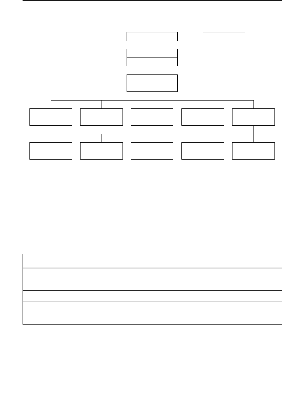
APCD-LM043-4.0 203
WaveRider CCU Enterprise MIBs
The structure of the CCU MIBs is illustrated in Figure 51.
Figure 51 CCU MIBs
Each of the MIBs in Figure 51 is discussed in the following sections.
CCU Base MIB
All values in Table 62, which are read only, are prefixed with 1. 3. 6.1.4.1. 2979.11.
Table 62 WaveRider CCU Base MIB
MIB Name OID Value Type Description
ccuGlobal 1 MIB CCU general data.
ccuRadioConfig 2MIB CCU configuration and setup data.
ccuRadioStats 3MIB CCU radio statistics.
ccuEtherStats 4MIB CCU Ethernet statistics
ccuModems 5MIB CCU registration and authorization information.
WaveRider (2979)
waverider
ccuGlobal
ccu3000pmacglob
ccuRadioConfig
ccu3000pmacradcfg
ccuRadioStats
ccu3000pmacrs
ccuEtherStats
ccu3000pmaces
ccuModem
ccu3000pmacmodem
ccuRadioStatsGeneral
ccu3000pmacrsgen
ccuRadioStatsDriver
ccu3000pmacrsdrv
ccuRadioStatsAtmel
ccu3000pmacrsatmel
ccuRegistration
ccu3000pmacreg
ccuAuthorization
ccu3000pmacauth
Enterprise (1.3.6.1.4.1)
LMS3000 CCU
ccu3000pmac
MIB Name
MIB File Prefix
Legend

204 APCD-LM043-4.0
CCU General Information Group
All values in Table 63 are prefixed with 1.3.6.1.4.1.2979.11.1.
Table 63 WaveRider CCU General Information Enterprise MIBs
CCU Radio Configuration Group
All CCU Radio Configuration Group MIB values are read only. All values in Table 64 are
prefixed with 1.3.6.1.4.1.2979.11.2.
Table 64 WaveRider CCU Radio Configuration Enterprise MIBs
MIB Name OID Value Type Status Accepted
Values Description
ccuSerialNumber 1 String R CCU hardware serial number
ccuSoftwareVersion 2String RCCU firmware version.
ccuHardwareVersion 3String RCCU hardware version.
ccuExtraFunctions 4Integer R 0 A mask for extra functionality that may
be added at a later date. For now, it
returns ‘0’.
ccuGlobalStatus 5Integer R1: startup
2: dead
3: ok
4: suspect
Current status of the radio interface.
For now, this field returns ‘ok’.
ccuGlobalSaveCounter 6Counter RA count of the number of times the
configuration is saved. Initially, this field
always returns ‘0’.
ccuGlobalConfigFiles 7String RA list of configuration files for the CCU.
The list is delimited with a semicolon;
i.e., “basic.cfg;route.cfg, ...”
ccuGlobalReset 8Integer W1: reset Not functional at this time.
ccuGlobalReload 9Integer W1: reload Not functional at this time.
MIB Name OID Value
Type Accepted
Values Description
ccuRadioConfigVersion 1 String Radio firmware version.
ccuRadioConfigMacAirlinkAddr 2Phys
Address
MAC address Radio MAC address.
ccuRadioConfigFrequency 3Integer Radio frequency in use (in 1/10ths of a
MHz)
ccuRadioConfigDomain 4Integer 0: IEEE
1: FCC or IC/
Canada
Current regulatory domain for which the
radio is configured.
ccuRadioHardwareRevision 5String Radio hardware revision.

APCD-LM043-4.0 205
CCU Radio Statistics Group
All CCU Radio Statistics Group MIB values are read only. All values in Table 65 are prefixed
with 1.3.6.1.4.1.2979.11.3.
Table 65 WaveRider CCU Radio Statistics MIB
CCU Radio General Statistics Group
All CCU Radio General Statistics Group MIB values are read only. All values in Table 66 are
prefixed with 1.3.6.1.4.1.2979.11.3.1.
Table 66 WaveRider CCU Radio General Statistics Group MIB
CCU Radio Driver Statistics Group
All CCU Radio Driver Statistics Group MIB values are read only. All values in Table 67 are
prefixed with 1.3.6.1.4.1.2979.11.3.2.
Table 67 WaveRider CCU Radio Driver Statistics Group MIB
MIB Name OID Value
Type Description
ccuRadioStatsGeneral 1 MIB General radio statistics.
ccuRadioStatsDriver 2MIB Radio driver statistics
ccuRadioStatsMAC 3MIB Radio MAC statistics.
MIB Name OID Value Type Description
ccuRadioGenRSSI 1 Integer Not used.
ccuRadioGenTPI 2Integer Radio transmit power indicator.
MIB Name OID Value Type Description
ccuRadioDrvEvents 1 Counter Number of interrupts received (any interrupt) in the radio
driver ISR (Interrupt Service Routine)
ccuRadioDrvRxComplete 2 Counter Number of receive complete interrupts received by the
radio driver ISR.
ccuRadioDrvTxComplete 3 Counter Number of transmit complete interrupts received by the
radio driver ISR.
ccuRadioDrvCmdComplete 4 Counter Number of command complete interrupts received by the
radio driver ISR.
ccuRadioDrvFatalEvent 5 Counter Number of fatal error interrupts received by the radio
driver ISR.
ccuRadioDrvTxPowerRailEvent 6 Counter Number of Tx Power alarm interrupts received by the
radio driver ISR.

206 APCD-LM043-4.0
CCU Radio MAC Statistics Group
All CCU Radio MAC Statistics Group MIB values are read only. All values in Table 68 are
prefixed with 1.3.6.1.4.1.2979.11.3.3.
Table 68 WaveRider CCU Radio MAC Statistics Group MIB
ccuRadioDrvUnknownEvent 7 Counter Number of received an unknown/no event interrupts
received by the radio driver ISR.
ccuRadioDrvSend 8 Counter Number of packets sent successfully by the radio driver
transmit queue.
ccuRadioDrvSendQFull 9 Counter Number of packets not sent because the radio driver
transmit queue was full.
ccuRadioDrvSendUnavailable 10 Counter Number of times invalid (null) mblks were sent to the radio
driver for transmission.
ccuRadioDrvSendNotEnabled 11 Counter Number of times tried to send packets before the radio
driver was started; i.e., before the device was up and
working.
ccuRadioDrvAMMPut 12 Counter Number of times a packet was successfully sent to the
MAC-layer shared memory for transmission over the air.
ccuRadioDrvAMMQFull 13 Counter Number of times a packet could not be sent to the MAC-
layer shared memory because there were no transmit
descriptors left. Radio driver tries 5 more times to send
the packet.
ccuRadioDrvAMMQFullDiscard 14 Counter Number of times, after 5 attempts, a packet could not be
sent to the MAC-layer shared memory because there
were no transmit descriptors left. Packet is discarded.
ccuRadioDrvGet 15 Counter Number of packets received from the MAC-layer shared
memory.
ccuRadioDrvQEmpty 16 Counter Number of times there was a receive interrupt, but nothing
available to read out of the MAC-layer shared memory.
ccuRadioDrvRx 17 Counter Number of successfully received packets.
ccuRadioDrvRxNotAvailable 18 Counter Number of times the radio driver could not allocate an
mblk (memory block) for storing a packet retrieved from
the MAC-layer shared memory.
ccuRadioDrvRxNotEnabled 19 Counter Number of times the radio driver received a receive
interrupt, but the radio driver was not yet up and running.
The received packet is ignored in this case.
MIB Name OID Value Type Description
MIB Name OID Value
Type Description
ccuRadioMACRxDataPayloads 1 Counter Number of Ethernet frames received correctly from
the air interface.
ccuRadioMACRxCtrlPayloads 2 Counter Number of control payloads received correctly from
the air interface.

APCD-LM043-4.0 207
ccuRadioMACRxPayloadFailInvalidType 3 Counter Number of times an unknown type of payload was
received from the air interface.
ccuRadioMACRxPayloadFailGiant 4 Counter Number of times a payload that was too long was
received from the air interface, and therefore
discarded.
CCURadioMACNullRxDesc 5 Counter Number of times the internal MAC receive interface
was corrupted.
ccuRadioMACTxDataPayloads 6 Counter Number of Ethernet frames transmitted to the air
interface.
ccuRadioMACTxCtrlPayloads 7 Counter Number of control payloads transmitted to the air
interface.
ccuRadioMACTxPayloadFailInvalidType 8 Counter Number of times a payload of an unknown type was
discarded.
ccuRadioMACTxPayloadFailGiant 9 Counter Number of times a payload that was too long was
discarded.
ccRadioMACTxPayloadFailInvalidDesc 10 Counter Number of times the internal MAC transmit interface
was corrupted.
ccuRadioMACTxBufferFullOnArrival 11 Counter Number of transmit packets that were queued for
delivery.
ccuRadioMACCmdTimeOuts 12 Counter Number of times the MAC-layer management
message was incomplete.
ccuRadioMACCmdMissedIRQs 13 Counter Number of times there was no response to the MAC-
layer management message.
ccuRadioMACFalseCmdIRQs 14 Counter Number of times a hardware IRQ was detected with
no message associated. This MIB parameter is used
primarily by software development.
ccuRadioMACCmdStatusErrors 15 Counter Number of times the MAC-layer management
message was rejected.
ccuRadioMACFatalError 16 Counter Number of nonrecoverable MAC-layer errors, each
causing a CCU reboot.
17 Reserved.
ccuRadioMACRxPacketsRedirected 18 Counter Number of times a reply from the EUM is received
with the correct HCRC (header cyclic redundancy
check).
Note: The name of this MIB is an error and should be
ccuRadioMACRxPacketsDirected.
ccuRadioMACRxPktsBroadcast 19 Counter Number of times an EUM succeeds in a random
access.
ccuRadioMACRxPktsNoMatch 20 Counter Number of packets correctly received, but not directed
to, this station.
ccuRadioMACRxPktsDuplicate 21 Counter Number of duplicate payloads (see note 1) received
and discarded. Indicates that a MAC layer
acknowledgement was lost.
MIB Name OID Value
Type Description

208 APCD-LM043-4.0
ccuRadioMACRxPktsRuntFail 22 Counter Number of packets received that were shorter than
the minimum size.
ccuRadioMACRxPktsLongFail 23 Counter Number of packets received that were longer than the
maximum size.
ccuRadioMACRxPktsHCRCFail 24 Counter Number of packets received with a MAC header CRC
failure (header corrupted).
ccuRadioMACRxPktsICVFail 25 Counter Number of packets received with an encryption (WEP,
wireless equivalent privacy) key mismatch (see note
3).
ccuRadioMACRxPktsFCSFail 26 Counter Number of packets received with a Frame Check
Sequence failure (payload corrupted).
ccuRadioMACRxPktsAssocFail 27 Counter Number of times a received packet had to be
discarded because too many EUMs were already
associated.
ccuRadioMACRxPktsIncomplete 28 Counter Number of times the receive DMA for a payload does
not complete (internal error).
ccuRadioMACRxPayloadsFailFull 29 Counter Number of times a received payload has to be
discarded because either no receive descriptor was
available, or there was not enough buffer space.
ccuRadioMACRxPayloadsDelivered 30 Counter Number of payloads that this station received
correctly.
ccuRadioMACRxPktsEmpty 31 Counter Number of packets received with no payload.
ccuRadioMACTxPkts 32 Counter Number of packets transmitted.
ccuRadioMACTxPktsEmpty 33 Counter Number of packets transmitted with no payload.
ccuRadioMACTxPayloads 34 Counter Number of payloads transmitted.
ccuRadioMACTxPayloadsBroadcast 35 Counter Number of broadcast payloads transmitted.
ccuRadioMACTxPayloads1Ok 36 Counter Number of payloads acknowledged after the first
transmission.
ccuRadioMACTxPayloads2Ok 37 Counter Number of payloads acknowledged after the second
transmission.
ccuRadioMACTxPayloads3Ok 38 Counter Number of payloads acknowledged after the third
transmission.
ccuRadioMACTxPayloads4Ok 39 Counter Number of payloads acknowledged after the fourth
transmission.
ccuRadioMACTxPayloadsFailRetry 40 Counter Number of payloads that failed to transmit due to the
retry limit.
ccuRadioMACTxPayloadsFailDeleted 41 Counter Number of payloads discarded from a queue that was
emptied when an EUM was deregistered due to non-
response or deauthorization.
ccuRadioMACTxPayloadsBadParam 42 Counter Number of payloads returned to the host because
they are improperly formed (internal error).
ccuRadioMACTxPayloadsVnetInactive 43 Counter Number of payloads returned to the host because the
virtual net was not active (internal error).
MIB Name OID Value
Type Description

APCD-LM043-4.0 209
Notes:
•Apacket is the basic unit of transmission. A packet may or may not contain a payload.
Apayload is user data, which may be an Ethernet frame or a logical link layer control
message.
• WEP is not supported in this release.
• The CCU maintains a transmit queue for each EUM. The length of this queue is
limited, to prevent one EUM from consuming all the resources and impacting service
to other EUMs. Discards indicate excessive load by one EUM, possibly due to large
TCP windows.
• Registration occurs once per EUM and/or CCU boot time. Deregistration may occur if
an EUM is not authorized (a registration/deregistration request pair occurs periodically
while that EUM is powered ON) or if the EUM does not respond to multiple
consecutive polls, such as when it is powered OFF.
• Association occurs when there is traffic to send to or from an EUM. Disassociation
occurs if there is no traffic to or from an EUM for a short period of time.
ccuRadioMACTxPayloadsAssocFail 44 Counter Number of payloads returned to the host because too
many other EUMs were already associated.
ccuRadioMACTxPayloadsTimeout 45 Counter Number of payloads returned to the host because of
timeout.
ccuRadioMACTxPayloadQueueTooLong 46 Counter Number of payloads returned to the host because the
transmit queue for the EUM was too long (see note 4).
47 Counter Not used.
ccuRadioMACReplyOrRssiTimeout 48 Counter Number of times that no response was received to a
directed poll.
ccuRadioMACRestarts 49 Counter Number of times that the MAC layer recovered from
an internal error or unexpected event.
ccuRadioMACRegRequests 50 Counter Number of registration requests received (see note 5).
ccuRadioMACRegResponse 51 Counter Number of registration responses transmitted (see
note 5).
ccuRadioMACDeregRequests 52 Counter Number of deregistration requests transmitted (see
note 5).
ccuRadioMACDeregInits 53 Counter Number of times no response was received from an
EUM, after multiple polls (see note 5). This statistic
indicates a poor radio link to one or more EUMs.
ccuRadioMACDisassociationRequests 54 Counter Number of disassociation requests transmitted (see
note 6).
ccuRadioMACDisassociationInits 55 Counter Number of times the CCU has determined than an
EUM should be disassociated (see note 6).
MIB Name OID Value
Type Description

210 APCD-LM043-4.0
CCU Ethernet Statistics Group
All CCU Ethernet Statistics Group MIB values are read only. All values in Table 69 are prefixed
with 1.3.6.1.4.1.2979.11.4.
Table 69 WaveRider CCU Ethernet Statistics Group MIB
MIB Name OID Value
Type Description
ccuEtherInterrupts 1 Counter Total number of interrupts received by the Ethernet
driver ISR, interrupt service routine.
ccuEtherRxInterrupt 2 Counter Number of receive complete interrupts received by the
Ethernet driver ISR.
ccuEtherRxOverrunInterrupt 3 Counter Number of overrun interrupts received by the Ethernet
driver ISR. An overrun occurs when a received packet
has exceeded the packet size, or the processor has
missed one or more packets.
ccuEtherRxInProgressInterrupt 4 Counter Number of times a receive complete interrupt was
received by the Ethernet driver ISR before the current
packet was finished.
ccuEtherTxCompleteInterrupt 5 Counter Number of normal transmit interrupts received by the
Ethernet driver ISR.
ccuEtherTxErrorInterrupt 6 Counter Number of transmit error interrupts received by the
Ethernet driver ISR.
ccuEtherTxCarrierLostInterrupt 7 Counter Number of transmit carrier lost interrupts received by
the Ethernet driver ISR.
ccuEtherTxAllocInterrupt 8 Counter Number of transmit allocation complete interrupts
received by the Ethernet driver ISR.
ccuEtherTxEPHInterrupt 9 Counter Number of transmit EPH interrupts (Ethernet protocol
handler interrupts) received by the Ethernet driver
ISR.
ccuEtherTxERCVInterrupts 10 Counter Number of transmit ERCV interrupts (early receive
interrupts) received by the Ethernet driver ISR..
ccuEtherRxData 11 Counter Number of packets received and accepted by the IP
stack.
ccuEtherRxDataError 12 Counter Number of packets received and rejected by the IP
stack because of errors.
ccuEtherRxDataMblkAllocError 13 Counter Number of packets lost due to insufficient memory
resources.
ccuEtherRxDataLenghtError 14 Counter Number of packets received that violate Ethernet
packet length rules.
ccuEtherRxDiscards 15 Counter Number of packets discarded because the unit was
not ready to receive data.
ccuEtherTxData 16 Counter Number of packets received and placed on the
transmit queue.
ccuEtherTxDataQFull 17 Counter Number of packets discarded because the transmit
queue was full.

APCD-LM043-4.0 211
CCU Modem Information MIB
All values in Table 70 are prefixed with 1.3.6.1.4.1.2979.11.5.
Table 70 WaveRider CCU Modem Information MIB
CCU Registration Information MIB
All CCU Registration MIB values are read only. All values in Table 71 are prefixed with
1.3.6.1.4.1.2979.11.5.1
Table 71 WaveRider CCU Registration Information MIB
CCU Registration Table
All CCU Registration Table Group MIB values are read only. All values in Table 72 are prefixed
with 1.3.6.1.4.1.2979.11.5.1.2.
Table 72 WaveRider CCU Registration Table MIB
ccuEtherTxOk 18 Counter Number of packets sent correctly.
ccuEtherTxTimeout 19 Counter Number of times the packet transmit has timed out.
ccuEtherTxSemWait 20 Counter Number of times a transmit semaphore could not be
taken in the timeout period.
MIB Name OID Value
Type Description
MIB Name OID Value
Type Description
ccuRegistration 1 MIB Registration Table.
ccuAuthorization 2MIB Authorization Table.
MIB Name OID Value
Type Description
ccuRegistrationCount 1 Integer Number of connections in the Registration Table.
ccuRegistrationTable 2MIB
MIB Name OID Value
Type Accepted
Values Description
ccuRegistrationIndex 1 Integer Index of entry in Registration Table.
ccuRegistrationId 2Integer 000000-FFFFFF Integer representation of the EUM ID,
normally displayed in hexadecimal.

212 APCD-LM043-4.0
CCU Authorization Information MIB
All CCU Authorization MIB values are read only. All values in Table 73 are prefixed with
1.3.6.1.4.1.2979.11.5.2.
Table 73 WaveRider CCU Authorization Table MIB
CCU Authorization Table
All CCU Authorization Table Group MIB values are read only. All values in Table 74 are
prefixed with 1.3.6.1.4.1.2979.11.5.2.2.
Table 74 WaveRider CCU Authorization Table MIB
CCU RFC MIB-II Traps
RFC MIB-II Traps
Table 75 CCU RFC MIB-II Traps
MIB Name OID Value
Type Description
ccuAuthorizationCount 1 Integer Number of authorized EUMs.
ccuAuthorizationTable 2MIB
MIB Name OID Type Accepted
Values Description
ccuAuthorizationIndex 1 Integer Index of entry in Authorization Table.
ccuAuthorizationId 2Integer 000000-
FFFFFF
Integer representation of the EUM ID, normally
displayed in hexadecimal.
ccuAuthorizationGosClass 3Integer 1: Best Effort
2: Bronze
3: Silver
4: Gold
5: Denied
The grade of service associated with the EUM.
MIB Name OID Description
coldStart 1.3.6.1.2.1.11.0.0 PowerCycleorPowerOn.
authenticationFailure 1.3.6.1.2.1.11.0.4 An SNMP request has failed due to improper
authentication.
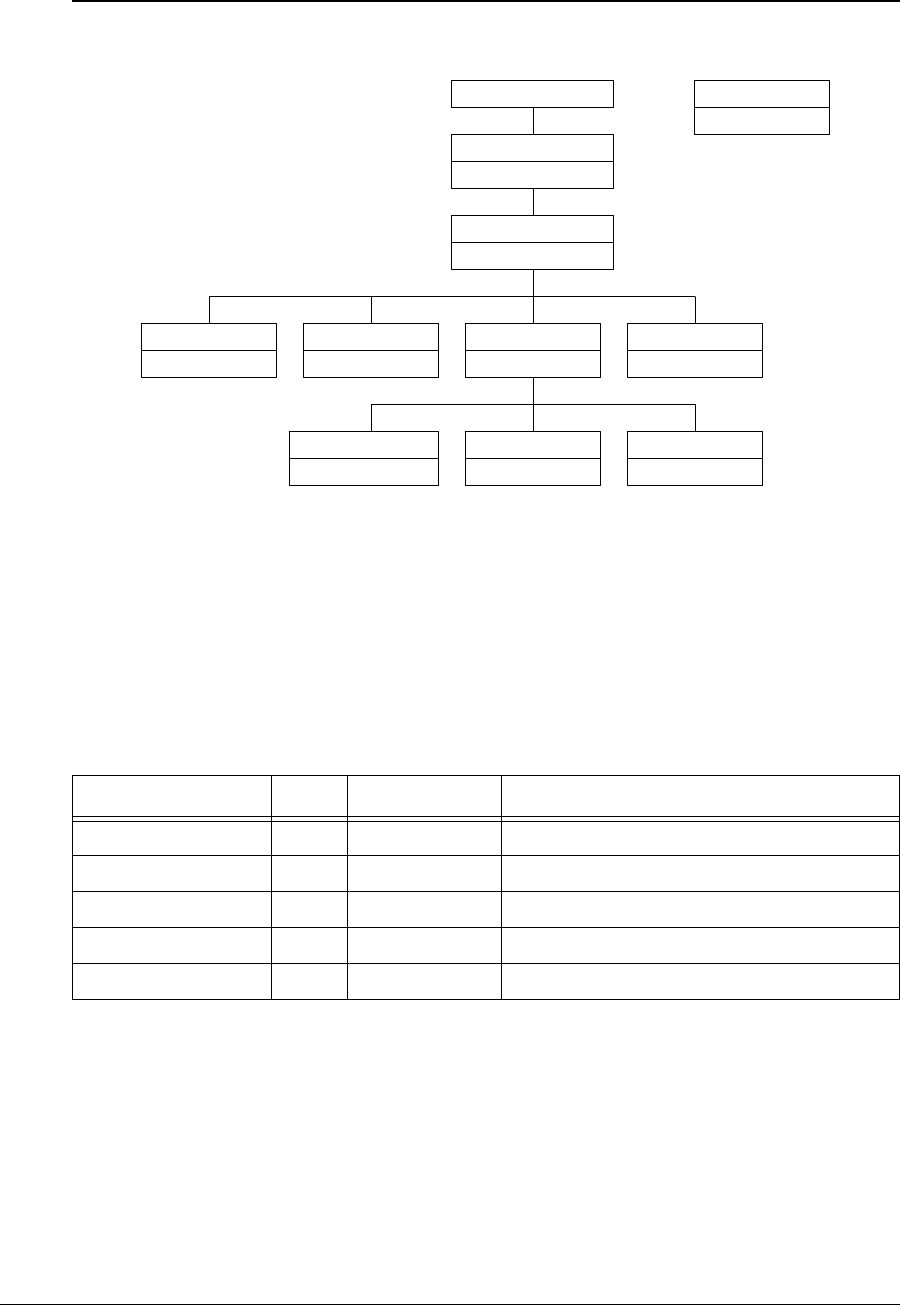
APCD-LM043-4.0 213
WaveRider EUM Enterprise MIBs
The structure of the EUM MIBs is illustrated in Figure 52.
Figure 52 EUM MIBs
Each of the MIBs in Figure 52 is discussed in the following sections.
EUM Base MIB
All values in Table 76, which are read only, are prefixed with 1. 3. 6.1.4.1. 2979.12.
Table 76 WaveRider EUM Base MIB
MIB Name OID Value Type Description
eumGlobal 1 MIB EUM general data.
eumRadioConfig 2MIB EUM configuration and setup data.
eumRadioStats 3MIB EUM radio statistics.
eumEtherStats 4MIB EUM Ethernet statistics
eumModems 5MIB EUM registration and authorization information.
WaveRider (2979)
waverider
eumGlobal
eum3000pmacglob
eumRadioConfig
eum3000pmacradcfg
eumRadioStats
eum3000pmacrs
eumEtherStats
eum3000pmaces
eumRadioStatsGeneral
eum3000pmacrsgen
eumRadioStatsDriver
eum3000pmacrsdrv
eumRadioStatsAtmel
eum3000pmacrsatmel
Enterprise (1.3.6.1.4.1)
LMS3000 EUM
eum3000pmac
MIB Name
MIB File Prefix
Legend

214 APCD-LM043-4.0
EUM General Information Group
All values in Table 77 are prefixed with 1.3.6.1.4.1.2979.12.1.
Table 77 WaveRider EUM General Information Enterprise MIBs
EUM Radio Configuration Group
All EUM Radio Configuration Group MIB values are read only. All values in Table 78 are
prefixed with 1.3.6.1.4.1.2979.12.2.
Table 78 WaveRider EUM Radio Configuration Enterprise MIBs
MIB Name OID Value Type Status Accepted
Values Description
eumSerialNumber 1 String R EUM hardware serial number
eumSoftwareVersion 2String REUM firmware version.
eumHardwareVersion 3String REUM hardware version.
eumExtraFunctions 4Integer R 0 A mask for extra functionality that may
be added at a later date. For now, it
returns ‘0’.
eumGlobalStatus 5Integer R1: startup
2: dead
3: ok
4: suspect
Current status of the radio interface.
For now, this field returns ‘ok’.
eumGlobalSaveCounter 6Counter RA count of the number of times the
configuration is saved. Initially, this field
always returns ‘0’.
eumGlobalConfigFiles 7String RA list of configuration files for the EUM.
The list is delimited with a semicolon;
i.e., “basic.cfg;route.cfg, ...”
eumGlobalReset 8Integer W1: reset Not functional at this time.
eumGlobalReload 9Integer W1: reload Not functional at this time.
MIB Name OID Value
Type Accepted
Values Description
eumRadioConfigVersion 1 String Radio firmware version.
eumRadioConfigMacAirlinkAddr 2Phys
Address
MAC address Radio MAC address.
eumRadioConfigFrequency 3Integer Radio frequency in use (in 1/10ths of a
MHz)
eumRadioConfigDomain 4Integer 0: IEEE
1: FCC or IC/
Canada
Current regulatory domain for which the
radio is configured.
eumRadioHardwareRevision 5String Radio hardware revision.

APCD-LM043-4.0 215
EUM Radio Statistics Group
All EUM Radio Statistics Group MIB values are read only. All values in Table 79 are prefixed
with 1.3.6.1.4.1.2979.12.3.
Table 79 WaveRider EUM Radio Statistics MIB
EUM Radio General Statistics Group
All EUM Radio General Statistics Group MIB values are read only. All values in Table 80 are
prefixed with 1.3.6.1.4.1.2979.12.3.1.
Table 80 WaveRider EUM Radio General Statistics Group MIB
EUM Radio Driver Statistics Group
All EUM Radio Driver Statistics Group MIB values are read only. All values in Table 81 are
prefixed with 1.3.6.1.4.1.2979.12.3.2.
Table 81 WaveRider EUM Radio Driver Statistics Group MIB
MIB Name OID Value
Type Description
eumRadioStatsGeneral 1 MIB General radio statistics.
eumRadioStatsDriver 2MIB Radio driver statistics
eumRadioStatsMAC 3MIB Radio MAC statistics.
MIB Name OID Value Type Description
eumRadioGenRSSI 1 Integer Radio receive signal strength indicator, in dBm. ‘0’
indicates no signal present.
MIB Name OID Value Type Description
eumRadioDrvEvents 1 Counter Number of interrupts received (any interrupt) in the radio
driver ISR (Interrupt Service Routine)
eumRadioDrvRxComplete 2 Counter Number of receive complete interrupts received by the
radio driver ISR.
eumRadioDrvTxComplete 3 Counter Number of transmit complete interrupts received by the
radio driver ISR.
eumRadioDrvCmdComplete 4 Counter Number of command complete interrupts received by the
radio driver ISR.
eumRadioDrvFatalEvent 5 Counter Number of fatal error interrupts received by the radio
driver ISR.
eumRadioDrvTxPowerRailEvent 6 Counter Number of Tx Power alarm interrupts received by the radio
driver ISR.

216 APCD-LM043-4.0
EUM Radio MAC Statistics Group
All EUM Radio MAC Statistics Group MIB values are read only. All values in Table 82 are
prefixed with 1.3.6.1.4.1.2979.12.3.3.
Table 82 WaveRider EUM Radio MAC Statistics Group MIB
eumRadioDrvUnknownEvent 7 Counter Number of received an unknown/no event interrupts
received by the radio driver ISR.
eumRadioDrvSend 8 Counter Number of packets sent successfully by the radio driver
transmit queue.
eumRadioDrvSendQFull 9 Counter Number of packets not sent because the radio driver
transmit queue was full.
eumRadioDrvSendUnavailable 10 Counter Number of times invalid (null) mblks were sent to the radio
driver for transmission.
eumRadioDrvSendNotEnabled 11 Counter Number of times tried to send packets before the radio
driver was started; i.e., before the device was up and
working.
eumRadioDrvAMMPut 12 Counter Number of times a packet was successfully sent to the
MAC-layer shared memory for transmission over the air.
eumRadioDrvAMMQFull 13 Counter Number of times a packet could not be sent to the MAC-
layer shared memory because there were no transmit
descriptors left. Radio driver tries 5 more times to send the
packet.
eumRadioDrvAMMQFullDiscard 14 Counter Number of times, after 5 attempts, a packet could not be
sent to the MAC-layer shared memory because there were
no transmit descriptors left. Packet is discarded.
eumRadioDrvGet 15 Counter Number of packets received from the MAC-layer shared
memory.
eumRadioDrvQEmpty 16 Counter Number of times there was a receive interrupt, but nothing
available to read out of the MAC-layer shared memory.
eumRadioDrvRx 17 Counter Number of successfully received packets.
eumRadioDrvRxNotAvailable 18 Counter Number of times the radio driver could not allocate an
mblk (memory block) for storing a packet retrieved from
the MAC-layer shared memory.
eumRadioDrvRxNotEnabled 19 Counter Number of times the radio driver received a receive
interrupt, but the radio driver was not yet up and running.
The received packet is ignored in this case.
MIB Name OID Value Type Description
MIB Name OID Value
Type Description
eumRadioMACRxDataPayloads 1 Counter Number of Ethernet frames received correctly from
the air interface.
eumRadioMACRxCtrlPayloads 2 Counter Number of control payloads received correctly from
the air interface.

APCD-LM043-4.0 217
eumRadioMACRxPayloadFailInvalidType 3 Counter Number of times an unknown type of payload was
received from the air interface.
eumRadioMACRxPayloadFailGiant 4 Counter Number of times a payload that was too long was
received from the air interface, and therefore
discarded.
eumRadioMACNullRxDesc 5 Counter Number of times the internal MAC receive interface
was corrupted.
eumRadioMACTxDataPayloads 6 Counter Number of Ethernet frames transmitted to the air
interface.
eumRadioMACTxCtrlPayloads 7 Counter Number of control payloads transmitted to the air
interface.
eumRadioMACTxPayloadFailInvalidType 8 Counter Number of times a payload of an unknown type was
discarded.
eumRadioMACTxPayloadFailGiant 9 Counter Number of times a payload that was too long was
discarded.
ccRadioMACTxPayloadFailInvalidDesc 10 Counter Number of times the internal MAC transmit interface
was corrupted.
eumRadioMACTxBufferFullOnArrival 11 Counter Number of transmit packets that were queued for
delivery.
eumRadioMACCmdTimeOuts 12 Counter Number of times the MAC-layer management
message was incomplete.
eumRadioMACCmdMissedIRQs 13 Counter Number of times there was no response to the MAC-
layer management message.
eumRadioMACFalseCmdIRQs 14 Counter Number of times a hardware IRQ was detected with
no message associated. This MIB parameter is used
primarily by software development.
eumRadioMACCmdStatusErrors 15 Counter Number of times the MAC-layer management
message was rejected.
eumRadioMACFatalError 16 Counter Number of nonrecoverable MAC-layer errors, each
requiring an EUM reboot.
17 Reserved.
eumRadioMACRxPacketsRedirected 18 Counter Number of times a poll for the EUM is received from
the CCU with the correct HCRC.
eumRadioMACRxPktsBroadcast 19 Counter Number of broadcast packets (see note 1) received
with the correct HCRC.
eumRadioMACRxPktsNoMatch 20 Counter Number of packets correctly received, but not directed
to, this station.
eumRadioMACRxPktsDuplicate 21 Counter Number of duplicate payloads (see note 1) received
and discarded. Indicates that a MAC layer
acknowledgement was lost.
eumRadioMACRxPktsRuntFail 22 Counter Number of packets received that were shorter than
the minimum size.
eumRadioMACRxPktsLongFail 23 Counter Number of packets received that were longer than the
maximum size.
MIB Name OID Value
Type Description

218 APCD-LM043-4.0
eumRadioMACRxPktsHCRCFail 24 Counter Number of packets received with a MAC header CRC
failure (header corrupted).
eumRadioMACRxPktsICVFail 25 Counter Number of packets received with an encryption (WEP,
wireless equivalent privacy) key mismatch (see note
3).
eumRadioMACRxPktsFCSFail 26 Counter Number of packets received with a Frame Check
Sequence failure (payload corrupted).
27 Not used. Returns a value of ‘0’.
eumRadioMACRxPktsIncomplete 28 Counter Number of times the receive DMA for a payload does
not complete (internal error).
eumRadioMACRxPayloadsFailFull 29 Counter Number of times a received payload has to be
discarded because either no receive descriptor was
available, or there was not enough buffer space.
eumRadioMACRxPayloadsDelivered 30 Counter Number of payloads that this station received
correctly.
eumRadioMACRxPktsEmpty 31 Counter Number of packets received with no payload.
eumRadioMACTxPkts 32 Counter Number of packets transmitted.
eumRadioMACTxPktsEmpty 33 Counter Number of packets transmitted with no payload.
eumRadioMACTxPayloads 34 Counter Number of payloads transmitted.
35 Not used. Returns a value of ‘0’.
eumRadioMACTxPayloads1Ok 36 Counter Number of payloads acknowledged after the first
transmission.
eumRadioMACTxPayloads2Ok 37 Counter Number of payloads acknowledged after the second
transmission.
eumRadioMACTxPayloads3Ok 38 Counter Number of payloads acknowledged after the third
transmission.
eumRadioMACTxPayloads4Ok 39 Counter Number of payloads acknowledged after the fourth
transmission.
eumRadioMACTxPayloadsFailRetry 40 Counter Number of payloads that failed to transmit due to the
retry limit.
41 Not used. Returns a value of ‘0’.
eumRadioMACTxPayloadsBadParam 42 Counter Number of payloads returned to the host because
they are improperly formed (internal error).
43 Not used. Returns a value of ‘0’.
44 Not used. Returns a value of ‘0’.
eumRadioMACTxPayloadsTimeout 45 Counter Number of payloads returned to the host because of
timeout.
46 Not used. Returns a value of ‘0’.
47 Not used. Returns a value of ‘0’
MIB Name OID Value
Type Description

APCD-LM043-4.0 219
Notes:
•Apacket is the basic unit of transmission. A packet may or may not contain a payload.
Apayload is user data, which may be an Ethernet frame or a logical link layer control
message.
• WEP is not supported in this release.
• Registration occurs once per EUM and/or CCU boot time. Deregistration may occur if
an EUM is not authorized (a registration/deregistration request pair occurs periodically
while that EUM is powered ON) or if the EUM does not respond to multiple
consecutive polls, such as when it is powered OFF.
• Association occurs when there is traffic to send to or from an EUM. Disassociation
occurs if there is no traffic to or from an EUM for a short period of time.
EUM Ethernet Statistics Group
All EUM Ethernet Statistics Group MIB values are read only. All values in Table 83 are prefixed
with 1.3.6.1.4.1.2979.12.4.
Table 83 WaveRider CCU Ethernet Statistics Group MIB
eumRadioMACReplyOrRssiTimeout 48 Counter Number of times the RSSI timer expired because the
EUM had not received anything from the CCU for
more than 0.5s.
eumRadioMACRestarts 49 Counter Number of times that the MAC layer recovered from
an internal error or unexpected event.
eumRadioMACRegRequests 50 Counter Number of registration requests transmitted (see note
4).
eumRadioMACRegResponse 51 Counter Number of registration responses received (see note
4).
eumRadioMACDeregRequests 52 Counter Number of deregistration requests received (see note
4).
53 Not used. Returns a value of ‘0’.
eumRadioMACDisassociationRequests 54 Counter Number of disassociation requests received (see note
5).
55 r Not used. Returns a value of ‘0’.
MIB Name OID Value
Type Description
MIB Name OID Value
Type Description
eumEtherInterrupts 1 Counter Total number of interrupts received by the Ethernet
driver ISR, interrupt service routine.
eumEtherRxInterrupt 2 Counter Number of receive complete interrupts received by the
Ethernet driver ISR.

220 APCD-LM043-4.0
eumEtherRxOverrunInterrupt 3 Counter Number of overrun interrupts received by the Ethernet
driver ISR. An overrun occurs when a received packet
has exceeded the packet size, or the processor has
missed one or more packets.
eumEtherRxInProgressInterrupt 4 Counter Number of times a receive complete interrupt was
received by the Ethernet driver ISR before the current
packet was finished.
eumEtherTxCompleteInterrupt 5 Counter Number of normal transmit interrupts received by the
Ethernet driver ISR.
eumEtherTxErrorInterrupt 6 Counter Number of transmit error interrupts received by the
Ethernet driver ISR.
eumEtherTxCarrierLostInterrupt 7 Counter Number of transmit carrier lost interrupts received by
the Ethernet driver ISR.
eumEtherTxAllocInterrupt 8 Counter Number of transmit allocation complete interrupts
received by the Ethernet driver ISR.
eumEtherTxEPHInterrupt 9 Counter Number of transmit EPH interrupts (Ethernet protocol
handler interrupts) received by the Ethernet driver
ISR.
eumEtherTxERCVInterrupts 10 Counter Number of transmit ERCV interrupts (early receive
interrupts) received by the Ethernet driver ISR..
eumEtherRxData 11 Counter Number of packets received and accepted by the IP
stack.
eumEtherRxDataError 12 Counter Number of packets received and rejected by the IP
stack because of errors.
eumEtherRxDataMblkAllocError 13 Counter Number of packets lost due to insufficient memory
resources.
eumEtherRxDataLenghtError 14 Counter Number of packets received that violate Ethernet
packet length rules.
eumEtherRxDiscards 15 Counter Number of packets discarded because the unit was
not ready to receive data.
eumEtherTxData 16 Counter Number of packets received and placed on the
transmit queue.
eumEtherTxDataQFull 17 Counter Number of packets discarded because the transmit
queue was full.
eumEtherTxOk 18 Counter Number of packets sent correctly.
eumEtherTxTimeout 19 Counter Number of times the packet transmit has timed out.
eumEtherTxSemWait 20 Counter Number of times a transmit semaphore could not be
taken in the timeout period.
MIB Name OID Value
Type Description

APCD-LM043-4.0 221
EUM RFC MIB-II Traps
RFC MIB-II Traps
Table 84 EUM RFC MIB-II Traps
MIB Name OID Description
coldStart 1.3.6.1.2.1.11.0.0 PowerCycleorPowerOn
authenticationFailure 1.3.6.1.2.1.11.0.4 An SNMP request has failed due to improper
authentication
—This page is intentionally left blank —

APCD-LM043-4.0 223
Appendix H Operating Statistics
The CCU and EUM provide a comprehensive set of operating statistics for each of the
following:
• Ethernet Port
• Radio Driver
•MACInterface
• Routing/Bridging Protocol
• Network Interface
• System Load (Radio Meter)
These statistics can be used as a diagnostic and troubleshooting tool when system
performance is being impaired by interference, radio link degradation, network problems,
atypical end-user applications, capacity issues, and so on.
All of these statistics are available through the command-line interface. Most of the statistics
are also available in the CCU and EUM MIBs, if you want to monitor the LMS4000 900 MHz
radio network from an SNMP manager.
CAUTION: Each CCU and EUM statistic is a maximum 32-bit
number (maximum 4,294,967,296). If a statistics counter exceeds
its maximum value, the counter resets to zero and begins again.
When this occurs, you must either take the rollover into account, or
reset the statistics to re-synchronize the counters. To reset
statistics, type stats clear at the command prompt and press Enter.
As a result of the above, the system uptime rolls over about every 8 days. By checking the
system log file, you can calculate the actual up time, after the unit has been up for more than 8
days.

224 APCD-LM043-4.0
To Display (all) Statistics from the CLI
• At the command prompt, type stats and press Enter.
The following sections describe each of the statistics in detail and the procedure for obtaining
specific sets of statistics (Ethernet, Radio, and so on).
Ethernet Statistics
Ethernet Statistics present operational information about data passing through the CCU and
EUM Ethernet ports. These statistics are described in Table 85.
As indicated in Table 85, all of the Ethernet statistics are available in a WaveRider MIB.
Table 85 Ethernet Statistics
Statistic Available
in MIB Description
Interrupts 3Total number of interrupts received by the
Ethernet driver ISR, interrupt service routine.
RX Interrupts 3Number of receive complete interrupts
received by the Ethernet driver ISR.
RX Overrun Interrupts 3Number of overrun interrupts received by the
Ethernet driver ISR. An overrun occurs when a
received packet has exceeded the packet
size, or the processor has missed one or more
packets.
RX In Progress Interrupts 3Number of times a receive complete interrupt
was received by the Ethernet driver ISR
before the current packet was finished.
TX Complete Interrupts 3Number of normal transmit interrupts received
by the Ethernet driver ISR.
TX Error Interrupts 3Number of transmit error interrupts received
by the Ethernet driver ISR.
TX Carrier Lost Interrupts 3Number of transmit carrier lost interrupts
received by the Ethernet driver ISR.
TX Alloc Interrupts 3Number of transmit allocation complete
interrupts received by the Ethernet driver ISR.
TX EPH Interrupts 3Number of transmit EPH interrupts (Ethernet
protocol handler interrupts) received by the
Ethernet driver ISR.
TX ERCV Interrupts 3Number of transmit ERCV interrupts (early
receive interrupts) received by the Ethernet
driver ISR.

APCD-LM043-4.0 225
To view the Ethernet statistics:
CCU> stats ethernet
-------------------- Ethernet Statistics -----------------------
Interrupts : 288647
RX Interrupts : 151103
RX Overrun Interrupts : 0
RX In Progress Interrupts : 4676
TX Complete Interrupts : 133189
TX Error Interrupts : 0
TX Carrier Lost Interrupts : 0
TX Alloc Interrupts : 0
TX EPH Interrupts : 0
TX ERCV Interrupts : 0
RX Data : 158095
RX Data Error : 0
RX Data Mblk Alloc Error : 0
RX Data Length Error : 0
RX Discards (No Space Available) : 18
TX Data : 133189
TX Data Q Full : 0
TX'D OK : 133189
TX Timeout : 0
TX Sem Wait : 0
CCU>
RX Data 3Number of packets received and accepted by
the IP stack.
RX Data Error 3Number of packets received and rejected by
the IP stack because of errors.
RX Data Mblk Error 3Number of packets lost due to insufficient
memory resources.
RX Data Length Error 3Number of packets received that violate
Ethernet packet length rules.
RX Discards 3Number of packets discarded because the unit
was not ready to receive data.
TX Data 3Number of packets received and placed on the
transmit queue.
TX Data Q Full 3Number of packets discarded because the
transmit queue was full.
TX’D OK 3Number of packets sent correctly.
TX Timeout 3Number of times the packet transmit has timed
out.
TX Sem Wait 3Number of times a transmit semaphore could
not be taken in the timeout period.
Statistic Available
in MIB Description

226 APCD-LM043-4.0
Radio Driver Statistics
Radio Driver Statistics present operational information about data passing through the CCU
and EUM radio driver and ports. These statistics are described in Table 86.
As indicated in Table 86, all of the Radio Driver statistics are available in a WaveRider MIB.
Table 86 Radio Driver Statistics
Statistic Available
in MIB Description
Events 3Number of interrupts received (any interrupt)
in the radio driver ISR (Interrupt Service
Routine)
Rx Complete Event 3Number of receive complete interrupts
received by the radio driver ISR.
Tx Complete Event 3Number of transmit complete interrupts
received by the radio driver ISR.
Cmd Complete Event 3Number of command complete interrupts
received by the radio driver ISR.
Fatal Error Event 3Number of fatal error interrupts received by
the radio driver ISR.
Tx Power Rail Event 3Number of Tx Power alarm interrupts received
bytheradiodriverISR.
Unknown Event 3Number of received an unknown/no event
interrupts received by the radio driver ISR.
Send 3Number of packets sent successfully by the
radio driver transmit queue.
Send Q Full 3Number of packets not sent because the radio
driver transmit queue was full.
Send End MBlk Unavailable 3Number of times invalid (null) mblks (memory
blocks) were sent to the radio driver for
transmission.
Send Not Enabled 3Number of times tried to send packets before
the radio driver was started; i.e., before the
device was up and working.
AMM Put 3Number of times a packet was successfully
sent to the MAC-layer shared memory for
transmission over the air.
AMM Q Full 3Number of times a packet was delayed before
beingplacedintheMAC-layersharedmemory
due to a full transmit queue.

APCD-LM043-4.0 227
To view the radio driver statistics:
CCU> stats ra
------------------- Radio Driver Statistics ---------------------
Events : 376194
Rx Complete Event : 184886
Tx Complete Event : 189052
Cmd Complete Event : 0
FATAL ERROR Event : 0
Tx Power Rail Event : 0
Unknown Event : 2348
Send : 189143
Send Q Full : 0
Send MBlk Unavailable : 0
Send Not Enabled : 0
AMM Put : 189143
AMM Q Full : 0
AMM Q Full Discard : 0
AMM get : 184886
AMM Q Empty : 99
Receive : 184886
Receive MBlk Unavailable : 0
Receive Not Enabled : 0
CCU>
AMM Q Full Discard 3Number of times a packet was discarded due
to the MAC-layer shared memory transmit
queue not draining.
AMM Get 3Number of packets received from the MAC-
layer shared memory.
AMM Q Empty 3Number of times there was a receive interrupt,
but nothing available to read out of the MAC-
layer shared memory.
Receive 3Number of successfully received packets.
Receive MBlk Unavailable 3Number of times the radio driver could not
allocate an mblk (memory block) for storing a
packet retrieved from the MAC-layer shared
memory.
Receive Not Enabled 3Number of times the radio driver received a
receive interrupt, but the radio driver was not
yet up and running. The received packet is
ignored in this case.
Statistic Available
in MIB Description

228 APCD-LM043-4.0
MAC Interface Statistics
MAC Interface Statistics present operational information about data which is processed by the
CCU and EUM MAC layer. These statistics are described in Table 87.
As noted in Table 87, most of the MAC interface statistics are available in a WaveRider MIB.
Table87 MACInterfaceStatistics
Statistic Available
in MIB Description (see note 2)
Rx Data Payloads 3Number of data payloads received correctly
from the air interface.
Rx Ctrl Payloads 3Number of control payloads received correctly
from the air interface.
Rx Payload Fail Invalid
Type
3Number of times an unknown type of payload
was received from the air interface.
Rx Payload Fail Giant 3Number of times a payload that was too long
was received from the air interface, and
therefore discarded.
Null Rx Descriptors 3Number of times the internal MAC receive
interface was corrupted.
Tx Data Payloads 3Number of data payloads transmitted to the air
interface.
Tx Ctrl Payloads 3Number of control payloads transmitted to the
air interface.
Tx Payload Fail Invalid
Type
3Number of times a payload of an unknown
type was discarded.
Tx Payload Fail Giant 3Number of times a payload that was too long
was discarded.
Tx Payload Fail Invalid
Desc
3Number of times the internal MAC transmit
interface was corrupted.
Atmel Tx Buffer full on
arrival
3Number of transmit packets that were queued
for delivery.
Command Time Outs 3Number of times the MAC-layer management
message was incomplete.
Command Missed IRQs 3Number of times there was no response to the
MAC-layer management message.
False Command IRQs 3Number of times a command failed because
the previous command was still being
processed.
Command Status Errors 3Number of times the MAC-layer management
message was rejected.

APCD-LM043-4.0 229
Atmel Fatal Error Not used.
Unused Statistic Not used.
rxPktsDirected 3At the CCU, the number of times a reply from
the EUM is received with the correct HCRC
(header cyclic redundancy check). In the
EUM, the number of times a poll for the EUM
is received from the CCU with the correct
HCRC.
rxPktsBroadcast 3At the CCU, the number of times an EUM
succeeds in a random access. Note that all
EUM packets are directed to the CCU, not
broadcast. At the EUM, the number of
broadcast packets (see note 1) received with
the correct HCRC. These are also random
access opportunities.
rxPktsNoMatch 3Number of packets correctly received, but not
directed to, this station.
rxPktsDuplicate 3Number of duplicate payloads (see note 1)
received and discarded. Indicates that a MAC
layer acknowledgement was lost.
rxPktsRuntFail 3Number of packets received that were shorter
than the minimum size.
rxPktsLongFail 3Number of packets received that were longer
than the maximum size.
rxPktsHCRCFail 3Number of packets received with a MAC
header CRC failure (header corrupted).
rxPktsICVFail 3Number of packets received with an
encryption (WEP, wireless equivalent privacy)
keymismatch(seenote3).
rxPktsFCSFail 3Number of packets received with a Frame
Check Sequence failure (payload corrupted).
rxPktsAssocFail 3Number of times a received packet had to be
discarded because too many EUMs were
already associated.[CCUonly]
rxPktsIncomplete 3Number of times the receive DMA for a
payload does not complete (internal error).
rxPayloadsFailFull 3Number of times a received payload has to be
discarded because either no receive
descriptor was available, or there was not
enough buffer space.
rxPayloadsDelivered 3Number of payloads that this station received
correctly.
Statistic Available
in MIB Description (see note 2)

230 APCD-LM043-4.0
rxPktsEmpty 3Number of packets received that are directed
to this station, but that did not contain a
payload.
txPkts 3Number of packets transmitted.
txPktsEmpty 3Number of packets transmitted with no
payload.
txPayloads 3Number of payloads transmitted.
txPayloadsBCast 3Number of broadcast payloads transmitted.
[CCU only]
txPayloads1Ok 3Number of payloads acknowledged after the
first transmission.
txPayloads2Ok 3Number of payloads acknowledged after the
second transmission.
txPayloads3Ok 3Number of payloads acknowledged after the
third transmission.
txPayloads4Ok 3Number of payloads acknowledged after the
fourth transmission.
txPayloadsFailRetry 3Number of payloads that failed to transmit due
to the retry limit.
txPayloadsFailAssocDeleted 3Number of payloads that were discarded
because the EUM was unreachable or
deauthorized. [CCU only]
txPayloadsFailBadParam 3Number of payloads returned to the host
because they are improperly formed (internal
error).
txPayloadsFailVnetInactive 3Number of payloads returned to the host
because the virtual net was not active (internal
error). [CCU only]
txPayloadsFailAssocFail 3Number of payloads returned to the host
because too many other EUMs were already
associated.[CCUonly]
txPayloadsFailTimeout 3Number of payloads returned to the host
because of timeout.
txPayloadsFailQueueTooLong 3Number of payloads returned to the host
because the transmit queue for the EUM was
too long (see note 4). [CCU only]
txPayloadsEmpty Not used.
Statistic Available
in MIB Description (see note 2)

APCD-LM043-4.0 231
Notes:
•Apacket is the basic unit of transmission. A packet may or may not contain a payload.
Apayload is user data, which may be an Ethernet frame or a logical link layer control
message.
• WEP is not supported in this release.
replyOrRssiTimeouts 3At the CCU, the number of times that no
response was received to a directed poll. At
the EUM, the number of times the RSSI timer
expired because the EUM had not received
anything from the CCU for more than 0.5s.
restarts 3Number of times that a PAI (physical
attachment interface) state machine restart
occurred (internal error).
registrationRequests 3At the CCU, the number of registration
requests received (see note 5). At the EUM,
the number of registration requests
transmitted (see note 5).
registrationResponses 3At the CCU, the number of registration
responses transmitted (see note 5). At the
EUM, the number of registration responses
received (see note 5).
deregistrationRequests 3At the CCU, the number of deregistration
requests transmitted (see note 5). At the EUM,
the number of deregistration requests
received (see note 5).
deregistrationInits 3Number of times no response was received
from an EUM, after multiple polls (see note 5).
[CCU only]
disassociationRequests 3At the CCU, the number of disassociation
requests transmitted (see note 6). At the EUM,
the number of disassociation requests
received (see note 6).
disassociationInits 3Number of times the CCU has determined
than an EUM should be disassociated (see
note 6). [CCU only]
newAssociations 3At the CCU, the number of times a new
association is created (see note 6). At the
EUM, the number of transitions to associated
state (see note 6).
currentAssociations 3Number of EUMs currently associated + 1
(see note 6). The one additional association is
for “broadcast”. [CCU only]
unexpectedEvents 3Number of internal unexpected events.
Statistic Available
in MIB Description (see note 2)

232 APCD-LM043-4.0
• The CCU maintains a transmit queue for each EUM. The length of this queue is
limited, to keep one EUM from consuming all the resources and impacting other
EUMs. Discards indicate excessive load by one EUM, possibly due to large TCP
windows.
• Registration occurs once per EUM and/or CCU boot time. Deregistration may occur if
an EUM is not authorized (a registration/deregistration request pair occurs periodically
while that EUM is powered ON) or if the EUM does not respond to multiple
consecutive polls, such as when it is powered OFF.
• Association occurs when there is traffic to send to or from an EUM. Disassociation
occurs if there is no traffic to or from an EUM for a short period of time.
To view the MAC Interface Statistics:
CCU> stats mac
----------------- MAC Interface Statistics --------------------
Rx Data Payloads : 132323
Rx Ctrl Payloads : 5702
Rx Payload Fail Invalid Type : 0
Rx Payload Fail Giant : 0
Null Rx Descriptors : 0
Tx Data Payloads : 138245
Tx Ctrl Payloads : 5702
Tx Payload Fail Invalid Type : 0
Tx Payload Fail Giant : 0
Tx Payload Fail Invalid Desc : 0
Atmel Tx Buffer full on arrival : 0
Command time outs : 0
Command missed IRQs : 0
False Command IRQs : 1766
Command Status Errors : 0
Atmel Fatal Errors : 0
Unused statistic : 0
rxPktsDirected: 2765984
rxPktsBroadcast: 2163
rxPktsNoMatch: 0
rxPktsDuplicate: 733
rxPktsRuntFail: 0
rxPktsLongFail: 0
rxPktsHCRCFail: 151
rxPktsICVFail: 0
rxPktsFCSFail: 23
rxPktsAssocFail: 0
rxPktsIncomplete: 0
rxPayloadsFailFull: 0
rxPayloadsDelivered: 138025
rxPktsEmpty: 2635068
txPkts: 16960762
txPktsEmpty: 16804869
txPayloads: 155893
txPayloadsBCast: 2040
txPayloads1Ok: 131286
txPayloads2Ok: 9423
txPayloads3Ok: 1027
txPayloads4Ok: 133
txPayloadsFailRetry: 27
txPayloadsFailAssocDeleted: 11
txPayloadsFailBadParam: 0
txPayloadsFailVnetInactive: 0
txPayloadsFailAssocFail: 0
txPayloadsFailTimeout: 0

APCD-LM043-4.0 233
txPayloadsFailQueueTooLong: 0
txPayloadsEmpty: 0
replyOrRssiTimeouts: 232598
restarts: 0
registrationRequests: 0
registrationResponses: 0
deregistrationRequests: 0
deregistrationInits: 0
disassociationRequests: 5671
disassociationInits: 5702
newAssociations: 5671
currentAssociations: 3
unexpectedEvents: 0
latestTx: 187
latestProg: 9881
latestTxPayload: 212
latestReply: 9912
lateReplyEum: 6294067
longestSearch: 127
txDescAvail: 74
CCU>
Routing/Bridging Protocol Statistics
Routing/Bridging Protocol Statistics present operational information about data which is
processed by the EUM bridging or CCU routing layer. These statistics are described in Table
88.
The Routing/Bridging Protocol Statistics are not available in the WaveRider MIBs.
Table 88 Routing/Bridging Protocol Statistics
Statistic Description
Rx Eth Dst - App Number of received Ethernet frames transferred
from the Ethernet port to the EUM application.
[EUM only]
Rx Eth Dst - Radio Number of received Ethernet frames bridged
from the Ethernet port to the radio port. [EUM
only]
Rx Eth Dst - To Router Number of received Ethernet frames transferred
from the Ethernet port to the CCU router
application. [CCU only]
Rx Eth Err - Mblk Number of Ethernet frames from the Ethernet
port that were discarded because of a specific
type of memory allocation error.
Rx Eth Err - Msg Buffer Number of Ethernet frames from the Ethernet
port that were discarded because of a specific
type of memory allocation error.

234 APCD-LM043-4.0
Rx Eth Err - Pkt Size Number of Ethernet frames from the Ethernet
port that were discarded because the frame was
too large or too small to decode.
Rx Eth Err - Unknown Ether Type Number of Ethernet frames from the Ethernet
port that were discarded because they were
neither IP nor ARP frames (example, IPX frame).
Rx Eth Err - Customer Table Error Number of Ethernet frames from the Ethernet
port that were discarded because the host was
not allowed air access. [EUM only]
Rx Eth Err - Invalid NetPool Number of Ethernet frames from the Ethernet
port that were discarded because of a specific
type of memory allocation error. [EUM only]
Rx Eth Dst - Unknown Number of Ethernet frames from the Ethernet
port that were discarded because the host is
known to be on the EUM’s Ethernet side. [EUM
only]
Rx Eth Err - Could not Duplicate Number of Ethernet frames from the Ethernet
port that were discarded because of a specific
type of memory allocation error. [EUM only]
Rx Eth Err - IP Filter Number of port-filtered Ethernet frames from the
Ethernet port.
Rx Radio Dst - App Number of Ethernet frames that were transferred
from the radio to the application layer.
Rx Radio Dst - Radio Number of Ethernet frames that were received
from the radio and transmitted back out through
the radio (i.e., “switched”). [CCU only]
Rx Radio Dst - To Router Number of Ethernet frames that were received
from the radio port and forwarded to the CCU
router application (i.e., destined for the CCU
application or gateway). [CCU only]
Rx Radio Dst - Eth Number of Ethernet frames from the radio port
that were bridged from the radio port to the
Ethernet port. [EUM only]
Rx Radio Err - Mblk Number of Ethernet frames from the radio port
that were discarded because of a specific type of
memory allocation error.
Rx Radio Err - Msg Buffer Number of Ethernet frames from the radio port
that were discarded because of a specific type of
memory allocation error.
Rx Radio Err - Pkt Size Number of Ethernet frames from the radio port
that were discarded because the frame was too
large or too small to decode.
Rx Radio Err - Unknown Ether Type Number of Ethernet frames from the radio port
that were discarded because they were neither
IP nor ARP frames (example, IPX frame).
Statistic Description

APCD-LM043-4.0 235
To view the Routing Protocol Statistics:
Rx Radio Err - Unknown Msg Type Number of Ethernet frames from the radio port
that were discarded because of an internal
routing error.
Rx Radio Err - Unreg Request Number of Ethernet frames received from the
radio port that were discarded because they
came from an unregistered EUM. [CCU only]
Rx Radio Err - Invalid NetPool Number of Ethernet frames received from the
radio port that were discarded because of a
specific type of memory allocation error.
Rx Radio Err - Could not Duplicate Number of Ethernet frames received from the
radio port that were discarded because of a
specific type of memory allocation error.
Rx Radio Err - Reflection Number of Ethernet frames received from the
radio port that were discarded because the
source address was on the EUM (split-horizon
rule). [EUM only]
Rx Radio Err - IP Filter Number of port-filtered Ethernet frames from the
radio port.
Tx Dst - Eth Number of Ethernet frames that were transmitted
through the Ethernet port.
Tx Dst - Radio Number of Ethernet frames that were transmitted
through the radio port.
Tx Err - Mblk Number of transmit Ethernet frames that had to
be discarded because of a specific type of
memory allocation error.
Tx Err - Msg Buffer Number of transmit Ethernet frames that had to
be discarded because of a specific type of
memory allocation error.
Tx Err - Pkt Size Number of transmit Ethernet frames that had to
be discarded because the frame was too large or
too small to decode.
Tx Dst - Unregistered Number of transmit Ethernet frames that had to
be discarded because they were for an
unregistered EUM. [CCU only]
Tx Dst - Unknown Number of transmit Ethernet frames that had to
be discarded because the Ethernet address did
not appear in the Address Table.
Tx Err - Invalid NetPool Number of transmit Ethernet frames that had to
be discarded because of a specific type of
memory allocation error. [EUM only]
Tx Err - Could not Duplicate Number of transmit Ethernet frames that had to
be discarded because of a specific type of
memory allocation error. [EUM only]
Statistic Description

236 APCD-LM043-4.0
CCU> stats rp
----------------Routing Protocol Statistics -----------------
Rx Eth Dst - Radio : 0
Rx Eth Dst - To Router : 154396
Rx Eth Err - Mblk (Discard) : 0
Rx Eth Err - Msg Buffer (Discard) : 0
Rx Eth Err - Pkt Size (Discard) : 0
Rx Eth Err - Unknown Ether Type (Discard) : 554
Rx Eth Err - IP Filter (Discard) : 0
Rx Radio Dst - App : 340
Rx Radio Dst - Radio : 1268
Rx Radio Dst - To Router : 129025
Rx Radio Dst - Eth : 0
Rx Radio Err - Mblk (Discard) : 0
Rx Radio Err - Msg Buffer (Discard) : 0
Rx Radio Err - Pkt Size (Discard) : 0
Rx Radio Err - Unknown Ether Type (Discard) : 0
Rx Radio Err - Unknown Msg Type (Discard) : 0
Rx Radio Err - Unreg Request (Discard) : 0
Rx Radio Err - Invalid NetPool (Discard) : 0
Rx Radio Err - Could not Duplicate (Discard) : 0
Rx Radio Err - IP Filter (Discard) : 0
Tx Dst - Eth : 131288
Tx Dst - Radio : 136286
Tx Err - Mblk (Discard) : 0
Tx Err - Msg Buffer (Discard) : 0
Tx Err - Pkt Size (Discard) : 0
Tx Dst - Unregistered (Discard) : 0
Tx Dst - Unknown (Discard) : 0
CCU>
Network Interface Statistics
Network Interface Statistics, described in Table 88, are generated by the IP-protocol suite
resident on the CCU and EUM.
Network Interface Statistics are not available in the WaveRider MIBs.
Table 89 Network Interface Statistics
To view all network interface statistics:
Statistic Description
ICMP For information on ICMP, and ICMP-related statistics, refer to RFC729.
IP For information on IP, and IP-related statistics, refer to RFC791.
TCP For information on TCP, and TCP-related statistics, refer to RFC793.
UDP For information on UDP, and UDP-related statistics, refer to RFC768.

APCD-LM043-4.0 237
CCU> stats net
To view network interface ICMP statistics:
CCU> stats net icmp
ICMP:
3133 calls to icmp_error
0 error not generated because old message was icmp
Output histogram:
destination unreachable: 3133
0 message with bad code fields
0 message < minimum length
0 bad checksum
0 message with bad length
Input histogram:
destination unreachable: 20
0 message response generated
CCU>
To view network interface IP statistics:
CCU> stats net ip
total 2181354
badsum 0
tooshort 0
toosmall 0
badhlen 0
badlen 0
infragments 0
fragdropped 0
fragtimeout 0
forward 1925975
cantforward 96917
redirectsent 0
unknownprotocol 20
nobuffers 0
reassembled 0
outfragments 0
noroute 2
Active Internet connections (including servers)
PCB Proto Recv-Q Send-Q Local Address Foreign Address (state)
-------- ----- ------ ------ ------------------ ------------------ -------
56d500 TCP 1 0 10.5.0.1.23 10.0.1.50.2687 ESTABLISHE
56c8d0 TCP 0 0 0.0.0.0.23 0.0.0.0.0 LISTEN
56c6c8 TCP 0 0 0.0.0.0.21 0.0.0.0.0 LISTEN
56cad8 UDP 0 0 0.0.0.0.123 0.0.0.0.0
56cbdc UDP 0 0 0.0.0.0.20001 0.0.0.0.0
56bb9c UDP 0 0 0.0.0.0.161 0.0.0.0.0
CCU>
In the above example, the active internet connections were:
Port 21 FTP
Port 23 Telnet (two sessions open)
Port 123 NTP
Port 161 SNMP
Port 20001 WaveRider private CCU load meter server
To view network interface TCP statistics;

238 APCD-LM043-4.0
CCU> stats net tcp
TCP:
536 packets sent
304 data packets (23557 bytes)
0 data packet (0 byte) retransmitted
222 ack-only packets (7 delayed)
0 URG only packet
0 window probe packet
0 window update packet
10 control packets
527 packets received
310 acks (for 23571 bytes)
7 duplicate acks
0 ack for unsent data
283 packets (485 bytes) received in-sequence
0 completely duplicate packet (0 byte)
0 packet with some dup. data (0 byte duped)
7 out-of-order packets (0 byte)
0 packet (0 byte) of data after window
0 window probe
0 window update packet
0 packet received after close
2 discarded for bad checksums
0 discarded for bad header offset field
0 discarded because packet too short
1 connection request
7 connection accepts
8 connections established (including accepts)
7 connections closed (including 0 drop)
0 embryonic connection dropped
309 segments updated rtt (of 311 attempts)
2 retransmit timeouts
0 connection dropped by rexmit timeout
0 persist timeout
0 keepalive timeout
0 keepalive probe sent
0 connection dropped by keepalive
0 pcb cache lookup failed
CCU>
To view the network interface UDP statistics
CCU> stats net udp
UDP:
247539 total packets
158004 input packets
89535 output packets
0 incomplete header
0 bad data length field
0 bad checksum
81429 broadcasts received with no ports
0 full socket
50202 pcb cache lookups failed
57 pcb hash lookups failed
UDP>

APCD-LM043-4.0 239
System Load Statistics (Radio Meter)
The radio meter command prints out a table of measurements that indicate the current load on
the system. These statistics are only available at the CCU. The load statistics are summarized
in Table 90. System Load Statistics are not available through the WaveRider MIBs.
Table 90 Load Statistics (Radio Meter)
Notes:
• All counters are continuous; that is, they are never zeroed, except if the unit is reset or
power cycled.
• Payload and poll counters can roll over after a minimum of 50 days.
• Byte counters can roll over after a minimum of 4 hours.
Statistic Description
Time Value of the CCU’s internal 32-bit microsecond timer at the instant the messages
were taken. Time rolls over to “0” about every hour and eleven minutes.
Fw Pyls Number of payloads transmitted from the CCU to EUMs in this class/level,
including retries.
Fw Bytes Number of bytes of payload transmitted from the CCU to EUMs in this class/
level, including retries.
Rev Pyls Number of payloads transmitted from EUMs in this class/level that are correctly
received by the CCU.
Rev Bytes Number of bytes of payload transmitted from EUMs in this class/level that are
correctly received by the CCU.
Max Vio MaxIPS Violations - Number of times the CCU has not polled an EUM in this
class/level within the inter-poll space defined by the EUM’s grade of service.
Ideal Vio
IdealIPS Violations - Number of times the average inter-poll space for EUMs in
this class/level has been more than 25% higher than the ideal inter-poll space
defined by the grade of service.
#EUMs Number of EUMs in the class/level at the instant in time the load statistics were
collected. The broadcast channel counts as one.
Avg IPS
Current low-pass average inter-poll space, in microseconds, for the class/level at
that instant in time, which corresponds to the current polling rate for EUMs in that
class. If no EUMs are currently in the class, it is the average taken at the time the
last EUM exited the class.
Total Polls Number of times the CCU has polled an EUM in the class/level.
Empty Polls Number of times the CCU has polled an EUM in the class/level and did not either
transmit or receive a payload.

240 APCD-LM043-4.0
• Violation counters could roll over after 70 seconds if the corresponding parameter was
set too small. A steeply climbing violation counter indicates serious problems with
either the settings or the system load.
To view the load statistics:
Console> radio meter
CCU Load Meter Time (us): 2388125184
Fw Pyls Fw Bytes Rev Pyls Rev Bytes Max Vio Ideal Vio
Gold Active 261996 117413346 233592 45583692 1 0
Gold Inactive 65145 3614618 3038 356335 0 0
Silver Active 885135 299817354 795036 131774471 0 2
Silver Inactive 50164 2246125 1283 172947 0 0
Bronze Active 20847 13538244 17727 2242378 0 0
Bronze Inactive 4098 178357 191 25156 0 0
BE Active 34294 2380443 3395 356844 0 97
BE Inactive 21443 708668 15808 688558 0 0
Broadcast 51436 2697875 48070 6848739 0 0
Overall 1394558 442595030 1118140 188049120 1 99
#EUMs Avg IPS Total Polls Empty Polls
Gold Active 0 21507 3017826 2577645
Gold Inactive 1 45867 2351419 2283292
Silver Active 0 1268 30527206 28936895
Silver Inactive 0 49800 1549140 1497712
Bronze Active 0 11906 257261 224260
Bronze Inactive 1 48111 125211 120926
BE Active 0 29463 707972 670633
BE Inactive 1 50472 1100549 1063487
Broadcast 1 1197 376559248 376459966
Console>
Each row on the above table, except for Overall, corresponds to a grade of service/activity
level combination. The last row is the overall totals, which in all cases except IPS, are the sum
of the entries in the column. Active refers to EUMs that have had traffic within the last
activePollTimeout, and Inactive refers to EUMs that have not had traffic within the last
activePollTimeout and have not timed out on disassociationTime. Therefore payload counts
for inactive EUMs indicate transitions from inactive to active.
NOTE: Broadcast traffic is carried with random access polls. Therefore,
forward traffic (CCU-to-EUM) in the broadcast row is broadcast
traffic, while reverse traffic is random access traffic. The reverse
packet rate should be less than 15% of the total poll rate for the
broadcast traffic, since random access attempts can collide.
Assuming uncorrelated arrivals, this should ensure that 99.7% of
random access attempts succeed (in four retries or less).

APCD-LM043-4.0 241
Appendix I IP Plan — Example
The following tables provide an example of an IP plan for an LMS4000 system equipped with
fifteen 900 MHz CAPs.
NAP IP Addressing Plan
Table 91 Example - CCU Ethernet Subnet Data
Table 92 Example - NAP IP Addressing Plan
Subnet 192.168.10.0
Subnet Mask Bits 24
Subnet Mask 255.255.255.0 (ff.ff.ff.00)
NAP Element IP Address
Gateway (NAP) Router 192.168.10.1 /24
NAP Switch 192.168.10.5 /24
NAP UPS 192.168.10.6 /24
SNMP Manager 192.168.10.7 /24

242 APCD-LM043-4.0
CCU Ethernet IP Addressing Plan
Table 93 Example - CCU Ethernet IP Addressing Plan
Site CCU CCU Ethernet
Address Site CCU CCU Ethernet
Address
CAP01 CCU01 192.168.10.11 CAP09 CCU01 192.168.10.139
CCU02 192.168.10.12 CCU02 192.168.10.140
CCU03 192.168.10.13 CCU03 192.168.10.141
CAP02 CCU01 192.168.10.27 CAP10 CCU01 192.168.10.155
CCU02 192.168.10.28 CCU02 192.168.10.156
CCU03 192.168.10.29 CCU03 192.168.10.157
CAP03 CCU01 192.168.10.43 CAP11 CCU01 192.168.10.171
CCU02 192.168.10.44 CCU02 192.168.10.172
CCU03 192.168.10.45 CCU03 192.168.10.173
CAP04 CCU01 192.168.10.59 CAP12 CCU01 192.168.10.187
CCU02 192.168.10.60 CCU02 192.168.10.188
CCU03 192.168.10.61 CCU03 192.168.10.189
CAP05 CCU01 192.168.10.75 CAP13 CCU01 192.168.10.203
CCU02 192.168.10.76 CCU02 192.168.10.204
CCU03 192.168.10.77 CCU03 192.168.10.205
CAP06 CCU01 192.168.10.91 CAP14 CCU01 192.168.10.219
CCU02 192.168.10.92 CCU02 192.168.10.220
CCU03 192.168.10.93 CCU03 192.168.10.221
CAP07 CCU01 192.168.10.107 CAP15 CCU01 192.168.10.235
CCU02 192.168.10.108 CCU02 192.168.10.236
CCU03 192.168.10.109 CCU03 192.168.10.237
CAP08 CCU01 192.168.10.123
CCU02 192.168.10.124
CCU03 192.168.10.125

APCD-LM043-4.0 243
CCU Radio IP Addressing Plan
Table 94 Example - CCU Radio Subnet Data
Table 95 Example - CCU Radio IP Addressing Plan
Subnet 172.16.0.0
Subnet Mask Bits 22
Subnet Mask 255.255.252.0 (ff.ff.fc.00)
Site CCU Subnet CCU Radio
IP Address CCU Radio Subnet Range Broadcast
CAP01 CCU01 172.16.4.0 172.16.4.1 172.16.4.1 - 172.16.7.254 172.16.7.255
CCU02 172.16.8.0 172.16.8.1 172.16.8.1 - 172.16.11.254 172.16.11.255
CCU03 172.16.12.0 172.16.12.1 172.16.12.1 - 172.16.15.254 172.16.15.255
CAP02 CCU01 172.16.16.0 172.16.16.1 172.16.16.1 - 172.16.19.254 172.16.19.255
CCU02 172.16.20.0 172.16.20.1 172.16.20.1 - 172.16.23.254 172.16.23.255
CCU03 172.16.24.0 172.16.24.1 172.16.24.1 - 172.16.27.254 172.16.27.255
CAP03 CCU01 172.16.28.0 172.16.28.1 172.16.28.1 - 172.16.31.254 172.16.31.255
CCU02 172.16.32.0 172.16.32.1 172.16.32.1 - 172.16.35.254 172.16.35.255
CCU03 172.16.36.0 172.16.36.1 172.16.36.1 - 172.16.39.254 172.16.39.255
CAP04 CCU01 172.16.40.0 172.16.40.1 172.16.40.1 - 172.16.43.254 172.16.43.255
CCU02 172.16.44.0 172.16.44.1 172.16.44.1 - 172.16.47.254 172.16.47.255
CCU03 172.16.48.0 172.16.48.1 172.16.48.1 - 172.16.51.254 172.16.51.255
CAP05 CCU01 172.16.52.0 172.16.52.1 172.16.52.1 - 172.16.55.254 172.16.55.255
CCU02 172.16.56.0 172.16.56.1 172.16.56.1 - 172.16.59.254 172.16.59.255
CCU03 172.16.60.0 172.16.60.1 172.16.60.1 - 172.16.63.254 172.16.63.255
CAP06 CCU01 172.16.64.0 172.16.64.1 172.16.64.1 - 172.16.67.254 172.16.67.255
CCU02 172.16.68.0 172.16.68.1 172.16.68.1 - 172.16.71.254 172.16.71.255
CCU03 172.16.72.0 172.16.72.1 172.16.72.1 - 172.16.75.254 172.16.75.255
CAP07 CCU01 172.16.76.0 172.16.76.1 172.16.76.1 - 172.16.79.254 172.16.79.255
CCU02 172.16.80.0 172.16.80.1 172.16.80.1 - 172.16.83.254 172.16.83.255
CCU03 172.16.84.0 172.16.84.1 172.16.84.1 - 172.16.87.254 172.16.87.255
CAP08 CCU01 172.16.88.0 172.16.88.1 172.16.88.1 - 172.16.91.254 172.16.91.255
CCU02 172.16.92.0 172.16.92.1 172.16.92.1 - 172.16.95.254 172.16.95.255
CCU03 172.16.96.0 172.16.96.1 172.16.96.1 - 172.16.99.254 172.16.99.255

244 APCD-LM043-4.0
CAP09 CCU01 172.16.100.0 172.16.100.1 172.16.100.1 - 172.16.103.254 172.16.103.255
CCU02 172.16.104.0 172.16.104.1 172.16.104.1 - 172.16.107.254 172.16.107.255
CCU03 172.16.108.0 172.16.108.1 172.16.108.1 - 172.16.111.254 172.16.111.255
CAP10 CCU01 172.16.112.0 172.16.112.1 172.16.112.1 - 172.16.115.254 172.16.115.255
CCU02 172.16.116.0 172.16.116.1 172.16.116.1 - 172.16.119.254 172.16.119.255
CCU03 172.16.120.0 172.16.120.1 172.16.120.1 - 172.16.123.254 172.16.123.255
CAP11 CCU01 172.16.124.0 172.16.124.1 172.16.124.1 - 172.16.127.254 172.16.127.255
CCU02 172.16.128.0 172.16.128.1 172.16.128.1 - 172.16.131.254 172.16.131.255
CCU03 172.16.132.0 172.16.132.1 172.16.132.1 - 172.16.135.254 172.16.135.255
CAP12 CCU01 172.16.136.0 172.16.136.1 172.16.136.1 - 172.16.139.254 172.16.139.255
CCU02 172.16.140.0 172.16.140.1 172.16.140.1 - 172.16.143.254 172.16.143.255
CCU03 172.16.144.0 172.16.144.1 172.16.144.1 - 172.16.147.254 172.16.147.255
CAP13 CCU01 172.16.148.0 172.16.148.1 172.16.148.1 - 172.16.151.254 172.16.151.255
CCU02 172.16.152.0 172.16.152.1 172.16.152.1 - 172.16.155.254 172.16.155.255
CCU03 172.16.156.0 172.16.156.1 172.16.156.1 - 172.16.159.254 172.16.159.255
CAP14 CCU01 172.16.160.0 172.16.160.1 172.16.160.1 - 172.16.163.254 172.16.163.255
CCU02 172.16.164.0 172.16.164.1 172.16.164.1 - 172.16.167.254 172.16.167.255
CCU03 172.16.168.0 172.16.168.1 172.16.168.1 - 172.16.171.254 172.16.171.255
CAP15 CCU01 172.16.172.0 172.16.172.1 172.16.172.1 - 172.16.175.254 172.16.175.255
CCU02 172.16.176.0 172.16.176.1 172.16.176.1 - 172.16.179.254 172.16.179.255
CCU03 172.16.180.0 172.16.180.1 172.16.180.1 - 172.16.183.254 172.16.183.255
Site CCU Subnet CCU Radio
IP Address CCU Radio Subnet Range Broadcast

APCD-LM043-4.0 245
EUM IP Addressing Plan
Table 96 Example - EUM Subnet Data
Table 97 Example - EUM IP Addressing Plan
Subnet 172.16.0.0
Subnet Mask Bits 22
Subnet Mask 255.255.252.0 (ff.ff.fc.00)
Site CCU Subnet ID EUM IP Address Range
CAP01 CCU01 EUM001-253 172.16.4.2 - 172.16.4.254
EUM254-300 172.16.5.1 - 172.16.5.47
CCU02 EUM001-253 172.16.8.2 - 172.16.8.254
EUM254-300 172.16.9.1 - 172.16.9.47
CCU03 EUM001-253 172.16.12.2 - 172.16.12.254
EUM254-300 172.16.13.1 - 172.16.13.47
CAP02 CCU01 EUM001-253 172.16.16.2 - 172.16.16.254
EUM254-300 172.16.17.1 - 172.16.17.47
CCU02 EUM001-253 172.16.20.2 - 172.16.20.254
EUM254-300 172.16.21.1 - 172.16.21.47
CCU03 EUM001-253 172.16.24.2 - 172.16.24.254
EUM254-300 172.16.25.1 - 172.16.25.47
CAP03 CCU01 EUM001-253 172.16.28.2 - 172.16.28.254
EUM254-300 172.16.29.1 - 172.16.29.47
CCU02 EUM001-253 172.16.32.2 - 172.16.32.254
EUM254-300 172.16.33.1 - 172.16.33.47
CCU03 EUM001-253 172.16.36.2 - 172.16.36.254
EUM254-300 172.16.37.1 - 172.16.37.47
CAP04 CCU01 EUM001-253 172.16.40.2 - 172.16.40.254
EUM254-300 172.16.41.1 - 172.16.41.47
CCU02 EUM001-253 172.16.44.2 - 172.16.44.254
EUM254-300 172.16.45.1 - 172.16.45.47
CCU03 EUM001-253 172.16.48.2 - 172.16.48.254
EUM254-300 172.16.49.1 - 172.16.49.47

246 APCD-LM043-4.0
CAP05 CCU01 EUM001-253 172.16.52.2 - 172.16.52.254
EUM254-300 172.16.53.1 - 172.16.53.47
CCU02 EUM001-253 172.16.56.2 - 172.16.56.254
EUM254-300 172.16.57.1 - 172.16.57.47
CCU03 EUM001-253 172.16.60.2 - 172.16.60.254
EUM254-300 172.16.61.1 - 172.16.61.47
CAP06 CCU01 EUM001-253 172.16.64.2 - 172.16.64.254
EUM254-300 172.16.65.1 - 172.16.65.47
CCU02 EUM001-253 172.16.68.2 - 172.16.68.254
EUM254-300 172.16.69.1 - 172.16.69.47
CCU03 EUM001-253 172.16.72.2 - 172.16.72.254
EUM254-300 172.16.73.1 - 172.16.73.47
CAP07 CCU01 EUM001-253 172.16.76.2 - 172.16.76.254
EUM254-300 172.16.77.1 - 172.16.77.47
CCU02 EUM001-253 172.16.80.2 - 172.16.80.254
EUM254-300 172.16.81.1 - 172.16.81.47
CCU03 EUM001-253 172.16.84.2 - 172.16.84.254
EUM254-300 172.16.85.1 - 172.16.85.47
CAP08 CCU01 EUM001-253 172.16.88.2 - 172.16.88.254
EUM254-300 172.16.89.1 - 172.16.89.47
CCU02 EUM001-253 172.16.92.2 - 172.16.92.254
EUM254-300 172.16.93.1 - 172.16.93.47
CCU03 EUM001-253 172.16.96.2 - 172.16.96.254
EUM254-300 172.16.97.1 - 172.16.97.47
CAP09 CCU01 EUM001-253 172.16.100.2 - 172.16.100.254
EUM254-300 172.16.101.1 - 172.16.101.47
CCU02 EUM001-253 172.16.104.2 - 172.16.104.254
EUM254-300 172.16.105.1 - 172.16.105.47
CCU03 EUM001-253 172.16.108.2 - 172.16.108.254
EUM254-300 172.16.109.1 - 172.16.109.47
Site CCU Subnet ID EUM IP Address Range

APCD-LM043-4.0 247
CAP10 CCU01 EUM001-253 172.16.112.2 - 172.16.112.254
EUM254-300 172.16.113.1 - 172.16.113.47
CCU02 EUM001-253 172.16.116.2 - 172.16.116.254
EUM254-300 172.16.117.1 - 172.16.117.47
CCU03 EUM001-253 172.16.120.2 - 172.16.120.254
EUM254-300 172.16.121.1 - 172.16.121.47
CAP11 CCU01 EUM001-253 172.16.124.2 - 172.16.124.254
EUM254-300 172.16.125.1 - 172.16.125.47
CCU02 EUM001-253 172.16.128.2 - 172.16.128.254
EUM254-300 172.16.129.1 - 172.16.129.47
CCU03 EUM001-253 172.16.132.2 - 172.16.132.254
EUM254-300 172.16.133.1 - 172.16.133.47
CAP12 CCU01 EUM001-253 172.16.136.2 - 172.16.136.254
EUM254-300 172.16.137.1 - 172.16.137.47
CCU02 EUM001-253 172.16.140.2 - 172.16.140.254
EUM254-300 172.16.141.1 - 172.16.141.47
CCU03 EUM001-253 172.16.144.2 - 172.16.144.254
EUM254-300 172.16.145.1 - 172.16.145.47
CAP13 CCU01 EUM001-253 172.16.148.2 - 172.16.148.254
EUM254-300 172.16.149.1 - 172.16.149.47
CCU02 EUM001-253 172.16.152.2 - 172.16.152.254
EUM254-300 172.16.153.1 - 172.16.153.47
CCU03 EUM001-253 172.16.156.2 - 172.16.156.254
EUM254-300 172.16.157.1 - 172.16.157.47
CAP14 CCU01 EUM001-253 172.16.160.2 - 172.16.160.254
EUM254-300 172.16.161.1 - 172.16.161.47
CCU02 EUM001-253 172.16.164.2 - 172.16.164.254
EUM254-300 172.16.165.1 - 172.16.165.47
CCU03 EUM001-253 172.16.168.2 - 172.16.168.254
EUM254-300 172.16.169.1 - 172.16.169.47
Site CCU Subnet ID EUM IP Address Range

248 APCD-LM043-4.0
Subscriber IP Addressing Plan
Table 98 Example - Subscriber Subnet Data
Table 99 Example - Subscriber IP Addressing Plan
CAP15 CCU01 EUM001-253 172.16.172.2 - 172.16.172.254
EUM254-300 172.16.173.1 - 172.16.173.47
CCU02 EUM001-253 172.16.176.2 - 172.16.176.254
EUM254-300 172.16.177.1 - 172.16.177.47
CCU03 EUM001-253 172.16.180.2 - 172.16.180.254
EUM254-300 172.16.181.1 - 172.16.181.47
Subnet 172.16.0.0
Subnet Mask Bits 22
Subnet Mask 255.255.252.0 (ff.ff.fc.00)
Site CCU Subnet ID Subscriber IP Address Range
CAP01 CCU01 SUB001-253 172.16.6.1 - 172.16.6.254
SUB254-300 172.16.7.1 - 172.16.7.46
CCU02 SUB001-253 172.16.10.1 - 172.16.10.254
SUB254-300 172.16.11.1 - 172.16.11.46
CCU03 SUB001-253 172.16.14.1 - 172.16.14.254
SUB254-300 172.16.15.1 - 172.16.15.46
CAP02 CCU01 SUB001-253 172.16.18.1 - 172.16.18.254
SUB254-300 172.16.19.1 - 172.16.19.46
CCU02 SUB001-253 172.16.22.1 - 172.16.22.254
SUB254-300 172.16.23.1 - 172.16.23.46
CCU03 SUB001-253 172.16.26.1 - 172.16.26.254
SUB254-300 172.16.27.1 - 172.16.27.46
Site CCU Subnet ID EUM IP Address Range

APCD-LM043-4.0 249
CAP03 CCU01 SUB001-253 172.16.30.1 - 172.16.30.254
SUB254-300 172.16.31.1 - 172.16.31.46
CCU02 SUB001-253 172.16.34.1 - 172.16.34.254
SUB254-300 172.16.35.1 - 172.16.35.46
CCU03 SUB001-253 172.16.38.1 - 172.16.38.254
SUB254-300 172.16.39.1 - 172.16.39.46
CAP04 CCU01 SUB001-253 172.16.42.1 - 172.16.42.254
SUB254-300 172.16.43.1 - 172.16.43.46
CCU02 SUB001-253 172.16.46.1 - 172.16.46.254
SUB254-300 172.16.47.1 - 172.16.47.46
CCU03 SUB001-253 172.16.50.1 - 172.16.50.254
SUB254-300 172.16.51.1 - 172.16.51.46
CAP05 CCU01 SUB001-253 172.16.54.1 - 172.16.54.254
SUB254-300 172.16.55.1 - 172.16.55.46
CCU02 SUB001-253 172.16.58.1 - 172.16.58.254
SUB254-300 172.16.59.1 - 172.16.59.46
CCU03 SUB001-253 172.16.62.1 - 172.16.62.254
SUB254-300 172.16.63.1 - 172.16.63.46
CAP06 CCU01 SUB001-253 172.16.66.1 - 172.16.66.254
SUB254-300 172.16.67.1 - 172.16.67.46
CCU02 SUB001-253 172.16.70.1 - 172.16.70.254
SUB254-300 172.16.71.1 - 172.16.71.46
CCU03 SUB001-253 172.16.74.1 - 172.16.74.254
SUB254-300 172.16.75.1 - 172.16.75.46
CAP07 CCU01 SUB001-253 172.16.78.1 - 172.16.78.254
SUB254-300 172.16.79.1 - 172.16.79.46
CCU02 SUB001-253 172.16.82.1 - 172.16.82.254
SUB254-300 172.16.83.1 - 172.16.83.46
CCU03 SUB001-253 172.16.86.1 - 172.16.86.254
SUB254-300 172.16.87.1 - 172.16.87.46
Site CCU Subnet ID Subscriber IP Address Range

250 APCD-LM043-4.0
CAP08 CCU01 SUB001-253 172.16.90.1 - 172.16.90.254
SUB254-300 172.16.91.1 - 172.16.91.46
CCU02 SUB001-253 172.16.94.1 - 172.16.94.254
SUB254-300 172.16.95.1 - 172.16.95.46
CCU03 SUB001-253 172.16.98.1 - 172.16.98.254
SUB254-300 172.16.99.1 - 172.16.99.97
CAP09 CCU01 SUB001-253 172.16.102.1 - 172.16.102.254
SUB254-300 172.16.103.1 - 172.16.103.46
CCU02 SUB001-253 172.16.106.1 - 172.16.106.254
SUB254-300 172.16.107.1 - 172.16.107.46
CCU03 SUB001-253 172.16.110.1 - 172.16.110.254
SUB254-300 172.16.111.1 - 172.16.111.46
CAP10 CCU01 SUB001-253 172.16.114.1 - 172.16.114.254
SUB254-300 172.16.115.1 - 172.16.115.46
CCU02 SUB001-253 172.16.118.1 - 172.16.118.254
SUB254-300 172.16.119.1 - 172.16.119.46
CCU03 SUB001-253 172.16.122.1 - 172.16.122.254
SUB254-300 172.16.123.1 - 172.16.123.46
CAP11 CCU01 SUB001-253 172.16.126.1 - 172.16.126.254
SUB254-300 172.16.127.1 - 172.16.127.46
CCU02 SUB001-253 172.16.130.1 - 172.16.130.254
SUB254-300 172.16.131.1 - 172.16.131.46
CCU03 SUB001-253 172.16.134.1 - 172.16.134.254
SUB254-300 172.16.135.1 - 172.16.135.46
CAP12 CCU01 SUB001-253 172.16.138.1 - 172.16.138.254
SUB254-300 172.16.139.1 - 172.16.139.46
CCU02 SUB001-253 172.16.142.1 - 172.16.142.254
SUB254-300 172.16.143.1 - 172.16.143.46
CCU03 SUB001-253 172.16.146.1 - 172.16.146.254
SUB254-300 172.16.147.1 - 172.16.147.46
Site CCU Subnet ID Subscriber IP Address Range

APCD-LM043-4.0 251
CAP13 CCU01 SUB001-253 172.16.150.1 - 172.16.150.254
SUB254-300 172.16.151.1 - 172.16.151.46
CCU02 SUB001-253 172.16.154.1 - 172.16.154.254
SUB254-300 172.16.155.1 - 172.16.155.46
CCU03 SUB001-253 172.16.158.1 - 172.16.158.254
SUB254-300 172.16.159.1 - 172.16.159.46
CAP14 CCU01 SUB001-253 172.16.162.1 - 172.16.162.254
SUB254-300 172.16.163.1 - 172.16.163.46
CCU02 SUB001-253 172.16.166.1 - 172.16.166.254
SUB254-300 172.16.167.1 - 172.16.167.46
CCU03 SUB001-253 172.16.170.1 - 172.16.170.254
SUB254-300 172.16.171.1 - 172.16.170.46
CAP15 CCU01 SUB001-253 172.16.174.1 - 172.16.174.254
SUB254-300 172.16.175.1 - 172.16.175.46
CCU02 SUB001-253 172.16.178.1 - 172.16.178.254
SUB254-300 172.16.179.1 - 172.16.179.46
CCU03 SUB001-253 172.16.182.1 - 172.16.182.254
SUB254-300 172.16.183.1 - 172.16.183.46
Site CCU Subnet ID Subscriber IP Address Range
—This page is intentionally left blank —

APCD-LM043-4.0 253
Appendix J Acronyms and Glossary
Table 100 Acronyms and Abbreviations
Acronym or
Abbreviation Definition
ABWM Advanced Bandwidth Manager
AC Alternating Current
API Application Programming Interface
ARP Address Resolution Protocol
ARQ Automatic Retry Request
ASCII American Standard Code for Information Interchange
BCF Basic Configuration File
CAP Communications Access Point
CCU CAP Channel Unit
CIR Committed Information Rate
CLI Command Line Interface
CPU Central Processing Unit
CSA Canadian Standards Association
CTS Clear To Send
dB decibel
dBi decibel—with respect to an isotropic radiator
DCE Data Communication Equipment
DES Data Encryption Standard
DHCP Dynamic Host Configuration Protocol
DNS Domain Name Server, Domain Network Server
DRAM Dynamic Random-access Memory

254 APCD-LM043-4.0
DSR Data Set Ready
DSSS Direct-sequence Spread Spectrum
DTE Data Terminal Equipment
ESD Electrostatic Discharge
ESN Electronic Serial Number
ETSI European Telecommunications Standards for Industry
EUM End-user Modem
FCC Federal Communications Commission (U.S.A.)
FRU Field Replaceable Unit
FTP File Transfer Protocol
GHz GigaHertz
GMT Greenwich Mean Time
GOS Grade of Service
HTTP HyperText Transfer Protocol
IC Industry Canada
ICMP Internet Control Message Protocol
ID Identifier, Identification
IP Internet Protocol
ISM Industrial, Scientific, and Medical (Unlicensed Radio Band)
ISP Internet Service Provider
LAN Local Area Network
LED Light-Emitting Diode
LMDS Local Multipoint Distribution System
LMS Last Mile Solution®
LOS Line Of Sight
MAC Media Access Control, Medium Access Controller
Mbps Megabits per second
MBR Maximum Burst Rate
MCF MAC Configuration File
MHz MegaHertz
MIB Management Information Base
MTU Maximum Transmission Unit
n/a not applicable
NAP Network Access Point
Acronym or
Abbreviation Definition

APCD-LM043-4.0 255
NAT Network Address Translation
NCL Network Communication Link
NTP Network Time Protocol
OAM Operations, Administration and Maintenance
OID Object Identifier
OS Operating System
PAT Port Address Translation
PC Personal Computer
PCF Permanent Configuration File
PHY Physical Layer
RADIUS Remote Access Dial-in User Service
RCF Route Configuration File
RF Radio Frequency
RIP Routing Information Protocol
RMA Returned Merchandise Authorization
RSSI Receive Signal Strength Indicator
RTS Request To Send
Rx Receive
SLA Service Level Agreement
SNMP Simple Network Management Protocol
SNTP Simple Network Time Protocol
SOHO Small Office/Home Office
SRAM Static Random Access Memory
TCP Transmission Control Protocol
TCP/IP Transmission Control Protocol/Internet Protocol
TDD Time-Division Duplex (Modulation)
TDMA Time-Division Multiple Access
Tx Transmit
UDP User Datagram Protocol
UL Underwriters Laboratories
UPS Uninterruptable Power Supply
UTC Universal Time Coordination
WRAP WaveRider Access Point
Acronym or
Abbreviation Definition

256 APCD-LM043-4.0
Table 101 LMS4000 Network Glossary
Term Definition
LMS4000 RF Subsystem The RF Equipment associated with an LMS4000, including
CCUs, RFSM, antennas, and transmission lines.
Bandwidth Manager The entity in the LMS4000 that uses various algorithms to
manage end-user access to the network interface bandwidth,
based on subscribed level of service.
Broadcast (Message) A message sent by one network device to all other devices
connected to the network.
Cell Size The nominal radius of the geographic area served by a single
CAP, within which EUMs can reliably receive service.
Channel Generally, the medium though which information is
communicated. In wireless communications, the channel is
usually defined by the center frequency, modulation type, and
occupied bandwidth.
CLI (Command Line
Interface) In contrast to a graphical user interface, a CLI is a
configuration and control interface based on keyboard-entry
commands and responses.
Console Port Typically, the 9–pin RS-232 serial port on an LMS device to
which a terminal or laptop computer is connected, for the
purpose of configuring or controlling the device.
Configuration Terminal The configuration terminal is provided for the purpose of
configuring or controlling a device directly through its console
port.
DNS (Domain Name
System) A database system that translates domain names into IP
addresses. For example, waverider.com is converted into
207.23.187.242.
DSSS (Direct-Sequence
Spread Spectrum) A form of spread-spectrum communications that uses a high-
speed code sequence, along with the information being sent,
to modulate the RF carrier.
Ethernet Switch In the context of LMS, the devices that provide data link layer
Ethernet connection between the router, NMS, UPS, and back
haul equipment at the LMS4000, and the CCUs, RFSM, back
haul equipment and UPS at the CAP.
Host Name The common name given to network devices to make them
more easily identifiable by network operators and maintenance
personnel.
Gateway A device connecting two networks that use different
communications technologies or protocols; for example, an IP/
Telephony Gateway provides a connection between an IP
network and a telephone network.

APCD-LM043-4.0 257
GOS (Grade of Service) A level of service associated with an EUM, which determines
how often, and when, an EUM will be polled. Since an EUM
can only send one packet each time it is polled, the data rate is
related to the polling rate.
IP (Internet Protocol) The network-layer protocol in the TCP/IP stack (defined by
RFC 791).
Line of Sight The radio link between a transmitter and receiver is said to be
line of sight if the direct path between the two is relatively free
from physical obstruction.
MAC (Medium Access
Control) The mechanism of managing access, by multiple users, to a
common transmission medium.
Multicast (Message) A message sent by a network device to a limited set of network
devices.
Orthogonal Channels Communications channels that can operate over a common
transmission medium without significantly interfering with each
other. In the context of LMS, radio frequencies on
appropriately spaced frequencies are considered to be
orthogonal.
OSPF (Open Shortest
Path First) A link-state, hierarchical interior gateway routing protocol that
can provide least-cost routing, multipath routing, and load
balancing.
NAT (Network Address
Translation) An Internet standard that enables a local area network to use
one set of IP addresses for internal traffic and another set of
addresses for external traffic.
PAT (Port Address
Translation) A feature that lets you number a LAN with inside local
addresses and filter them through one globally routable IP
address.
Point-to-Multipoint A communications architecture in which a central station
(CAP, for example) communicates with multiple remote
stations (EUMs).
POTS (Plain Old
Telephone Service) The basic telephone service provided by the public switched
telephone network (PSTN).
Radio Module The device in the EUM (or CCU) that provides the wireless
interface to the LMS network. The radio module performs
signal spreading and modulation, channelization, up-
conversion and amplification in the transmit direction, and
signal amplification, down-conversion, channel selection,
demodulation, de-spreading and data recovery in the receive
direction.
Range The maximum distance that a signal can be reliably
transmitted between a CCU and EUM.
Term Definition

258 APCD-LM043-4.0
RIP (Routing Information
Protocol) A routing protocol in which network routers periodically
broadcast their entire current routing database.
Router A network device that routes IP messages from one physical
port to another based on a table of routes that are manually
entered by a crafts person (static routes) or generated by the
router using a routing protocol such as RIP or OSPF.
Routing The process of finding a path to a destination host through an
IP network.
Sectorization An RF engineering technique whereby co-located transceivers
are connected to separate antennas with different but
geometrically arranged azimuths, for the purpose of optimizing
radio frequency reuse, extending range, and reducing
interference. 120° sectorization is commonly applied in LMS
systems.
SNMP (Simple Network
Management Protocol) A protocol used to manage nodes in an IP network.
SNMP Agent An agent resides on an SNMP-managed device, and performs
operations when requested to do so by an SNMP manager.
SNMP Community A grouping of SNMP agents that can be managed by an
SNMP manager. An SNMP manager can manage more than
one SNMP community. The community name is used to
authenticate the SNMP manager before allowing it access to
the agent.
SNMP MIB (Management
Information Base) The information that an SNMP manager, such as the NMS,
can request from an SNMP agent.
SNMP Trap A message sent by an SNMP agent to an NMS, console, or
terminal to indicate the occurrence of a significant event, such
as a specified condition, or a defined threshold that was
reached.
SNMP Trap Server The server to which SNMP trap messages are forwarded.
SNTP (Simple Network
Time Protocol) A feature that provides LMS4000 devices with an accurate
time clock for time stamping events in a log file.
Spread Spectrum A communication technology in which the transmitted signal
occupies a much greater bandwidth than the information
bandwidth. The benefits of spread spectrum are generally
lower spectral power density, and immunity to noise,
interference and jamming.
Static Route A route that is manually entered into a routing table by a crafts
person or network operator.
Subscriber In the context of LMS, it is the individual or entity associated
with an EUM.
Term Definition

APCD-LM043-4.0 259
TCP (Transmission
Control Protocol) The connection-oriented transport layer protocol that provides
reliable, full-duplex data transmission in TCP/IP networks.
Telnet A terminal emulation program for TCP/IP networks.
UDP (User Datagram
Protocol) Part of the TCP/IP protocol suite, which provides a way for
applications to access the connectionless features of IP. It
provides for exchange of datagrams without
acknowledgements or guaranteed delivery.
Unicast A message sent by one network device to another network
device.
User Authentication In LMS, the secure mechanism through which a user
identification is verified.
User Authorization The secure mechanism by which a user is approved to use
LMS services. To illustrate, an EUM may be authenticated but
denied service because of the delinquent payment of a bill.
VoIP (Voice over IP) The ability to carry normal telephony-style voice over an IP-
based internet, with POTS-like functionality, reliability and
voice quality.
Term Definition
—This page is intentionally left blank —

APCD-LM043-4.0 261
Index
A
acronyms ......................253
antenna ..................... 17,20
antenna guidelines ........ 181,241
connector ....................31
control ......................31
Atmel statistics ..................228
B
backhaul .......................156
bandpass filters ...................63
broadcast applications ..............46
C
C/I requirements ..................68
CAP ...........................14
cavity filters ......................17
CCU ...........................15
configuration ............. 7,22,83
data tables ..................183
receive statistics ..............131
testing communications ...........9
transmit statistics..............127
CCU Shelf.......................18
center illumination .................65
channel bandwidth.................28
channels ........................29
colocated ....................30
cleaning .......................125
command-line interface .............76
command-line syntax..............163
community strings .................51
connectors ......................74
corner illumination .................66
customer list .....................51
D
data rate ........................30
data tables .....................183
data transmission .................24
DHCP relay......................48
duplexing .......................30
E
equipment........................5
Ethernet
cable wiring..................152
statistics ....................224
Ethernet switch ...................17
EUM ...........................19
adding ......................12
antenna .....................20
backhaul ....................156
configuration ............. 8,22,97
Configuration Utility .............77
data tables ..................183
installation...................105
registration ...................25
statistics ....................132
testing communications ...........9
thin route....................155
external interference ...............69
F
factory configuration ..............159
field upgrade process...............80
frequency band ...................28
frequency selection ................67
FTP ........................ 78,81
G
glossary .......................253
GOS ...........................39
H
humidity .......................125
I
in-band interference................61
indicators .......................74
Internet connection ................11
IP addressing ....................53
IP planning .....................241
L
lightning arrestors .............. 17,22
M
MAC layer.......................36
maintenance ....................125
cleaning ....................125
humidity ....................125

262 APCD-LM043-4.0
temperature..................125
MDR statistics ...................226
MIBs...........................52
modulation ......................29
N
NAT ...........................57
network monitoring ............ 47,127
O
operating statistics.................79
out-of-band interference.............61
P
performance modelling..............42
periodic packet sources .............46
ping commands..................197
Polling MAC .....................36
statistics .....................42
port filtering ......................49
propagation path ..................31
protocol stacks ...................24
R
receive sensitivity .................31
receive statistics .................131
RF coverage .....................64
RF design guidelines ...............71
RF distribution panel ...............18
RFSM ..........................17
routing protocol statistics ...........233
S
SNMP....................... 51,80
community strings ..............51
MIBs........................52
SNTP time clock ..................50
software license agreement ...........ii
specifications ............... 157,199
spectral survey ...................60
statistics
Atmel ......................228
Ethernet ....................224
MDR.......................226
routing protocol ...............233
system loading ...................66
T
temperature.....................125
testing communications ..............9
thin route.......................155
time clock .......................50
transmission line ............... 17,21
transmit power....................30
transmit queue limits ...............42
transmit statistics.................127
troubleshooting ..................135
U
UPS ...........................18
UTC time clock ...................50
V
verification checklist................70
VoIP ...........................47
W
warranty ........................ iv
—This page is intentionally left blank —

Telephone: +1 416–502–3161
Fax: +1 416–502–2968
Email: techsupport@waverider.com
URL: www.waverider.com