Vecima Networks EUM3004 Wireless LAN end-users modem User Manual LMS4000 900 MHz Guide
Vecima Networks Inc. Wireless LAN end-users modem LMS4000 900 MHz Guide
Contents
- 1. User Manual LMS4000 900 MHz Part 2
- 2. User Manual LMS4000 900MHz Part 1
- 3. User Manual note
User Manual LMS4000 900 MHz Part 2

156 APCD-LM043-8.0 (DRAFT C)
9: Installing the EUM
9.4.9 Obtaining Valid IP Addresses for the End-user’s PC
To obtain IP addresses for the end-user’s PC, including the PC IP address, Gateway IP
address, and DNS server address, the PC must request an update from the DHCP server.
This procedure varies depending on which operating system is running on the end-user’s PC,
but a general method is outlined as follows.
NOTE: The subscriber PC may obtain a dynamic IP through DHCP, or it
may use a static IP and DNS server.
To Obtain a Valid IP Address for the End-user’s PC (Windows XP)
1. Open a command prompt window.
2. At the prompt, type ipconfig/release and press Enter.
3. Type
ipconfig/renew and press Enter.
4. If no error messages are returned, the WISP network has successfully provided an IP
address to the end-user’s PC.
9.4.10 Testing the Data Link
The fact that the IP address was successfully obtained indicates that the data link from the PC
to the WISP's network is functioning properly. WaveRider recommends more thorough testing
of the EUM-to-CCU data link, as outlined below. These tests can also be used to troubleshoot
simple problems if DHCP access is not available.
There are several tools available for testing the quality of the link between the end-user PC
and the WISP network. The most important tool is the “file get” test, which tests the quality of
the data link. You can also use the ping command to progressively test presence of the data
link. The procedures for running the “file get” throughput tests and “ping” data link tests are
described below.
To Run a “File Get” Throughput Test From the EUM
1. Open the EUM console, as described in Access Interface on page 221.
2. At the prompt, type file get <ccu_ip_address>, and press Enter.
WaveRider Communications, Inc. LMS3000
Password:
60:ff:fe> file get 192.168.1.21
Enter password:
file transfer started (press 'qqq' to abort)...
bytes processed: 2097152 at 829 kbps
file transfer complete
Transfered "/tffs0/null" Okay.
60:ff:fe>
To Run a “File Get” Throughput Test From the CCU
1. Establish a Telnet connection to the CCU.
2. At the prompt, type file get <eum_ip_address>, and press Enter.
9: Installing the EUM
APCD-LM043-8.0 (DRAFT C) 157
WaveRider Communications, Inc. LMS3000
Password:
60:03:3a> file get 192.168.10.250
Enter password:
file transfer started (press 'qqq' to abort)...
by 2097152 at 183 kbps24 at 201 kbps
file transfer complete
Transfered "/tffs0/null" Okay.
60:03:3a>
The following three tests use the “ping” command to progressively test the data link.
To Test the Data Link from the End-user’s PC to the EUM
1. Ping the EUM’s IP address from the end-user’s PC, as follows:
• Open a DOS window in the end-user’s PC.
• At the command prompt, type ping <aaa.bbb.ccc.ddd>, where
<aaa.bbb.ccc.ddd> is the IP address of the EUM and press Enter.
2. If there is no response, check the following:
• PC IP address settings.
• Ethernet crossover cable between the EUM and the end-user’s PC, to ensure
that the pins have not been damaged.
3. If there is a response, but with errors, check the Ethernet crossover cable.
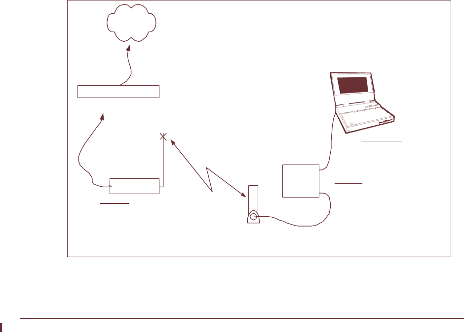
To illustrate data link testing between the PC and the EUM, consider the sample configuration
shown in Figure 60.
Figure 60 Sample Configuration — Testing the Data Link
Ethernet crossover
cable
EUM Antenna
Gateway Router
Internet
Radio
Link
End-user's Premises
End-user's PC
IP Address 172.16.6.1
Net Mask 22
Gateway IP 172.16.4.1
EUM3000
IP Address 172.16.4.2
Net Mask 22
Gateway IP 172.16.4.1
CCU3000
Radio IP Address
172.16.4.1
Net Mask 22

158 APCD-LM043-8.0 (DRAFT C)
9: Installing the EUM
Using the sample configuration shown in Figure 60, confirm the connection between the end-
user’s PC and the EUM as demonstrated below:
This is what successful ping from the end-user’s PC to the EUM looks like:
C:\>ping 172.16.6.1
Pinging 172.16.6.1 with 32 bytes of data:
Reply from 172.16.6.1: bytes=32 time<10ms TTL=64
Reply from 172.16.6.1: bytes=32 time<10ms TTL=64
Reply from 172.16.6.1: bytes=32 time<10ms TTL=64
Reply from 172.16.6.1: bytes=32 time<10ms TTL=64
Ping statistics for 172.16.6.1:
Packets: Sent = 4, Received = 4, Lost = 0 (0% loss),
Approximate round trip times in milli-seconds:
Minimum = 0ms, Maximum = 0ms, Average = 0ms
C:\>
This is what an unsuccessful ping from the end-user’s PC to the EUM looks like:
C:\>ping 172.16.10.1
Pinging 172.16.10.1 with 32 bytes of data:
Request timed out.
Request timed out.
Request timed out.
Request timed out.
Ping statistics for 172.16.10.1:
Packets: Sent = 4, Received = 0, Lost = 4 (100% loss),
Approximate round trip times in milli-seconds:
Minimum = 0ms, Maximum = 0ms, Average = 0ms
C:\>
Testing the Data Link from the End-user’s PC to the Network
Once the connection from the PC to the EUM is confirmed, ping the EUM gateway address
from a PC DOS window. Ping with short packets first to confirm function, and then with long
packets (1472 byte packets) to confirm performance. Errors observed on pings with long
packets indicate a high error rate on the channel, caused by low signal levels or interference.
To Ping a CCU with the Maximum Packet Size
1. Open a DOS window.
2. At the command prompt, type ping <aaa.bbb.ccc.ddd> -t -L 1472, where
<aaa.bbb.ccc.ddd> is the CCU radio IP address and press Enter.
3. Press
Ctrl+c to end the test.
NOTE: If this test fails, but pinging the CCU with the default packet size
succeeds, then the connection is working but is not operating at
maximum capacity, possibly due to poor antenna placement or
orientation.

9: Installing the EUM
APCD-LM043-8.0 (DRAFT C) 159
This following example uses the sample configuration shown in Figure 60:
Pinging the CCU from the end-user’s PC (with maximum packet size):
C:\>ping 172.16.4.1 -t -l 1472
Pinging 172.16.4.1 with 1472 bytes of data:
Reply from 172.16.4.1: bytes=1472 time=40ms TTL=64
Reply from 172.16.4.1: bytes=1472 time=81ms TTL=64
Reply from 172.16.4.1: bytes=1472 time=80ms TTL=64
Reply from 172.16.4.1: bytes=1472 time=40ms TTL=64
Reply from 172.16.4.1: bytes=1472 time=60ms TTL=64
Reply from 172.16.4.1: bytes=1472 time=80ms TTL=64
Reply from 172.16.4.1: bytes=1472 time=40ms TTL=64
Reply from 172.16.4.1: bytes=1472 time=110ms TTL=64
Ping statistics for 172.16.4.1:
Packets: Sent = 8, Received = 8, Lost = 0 (0% loss),
Approximate round trip times in milli-seconds:
Minimum = 40ms, Maximum = 110ms, Average = 66ms
Control-C
^C
C:\>
Testing the Data Link from the End-user’s PC to the Internet
Use the following test to determine whether the end-user’s PC can communicate with the
Internet.
Pinging an Internet site from the PC using the site’s IP address:
C:\>ping 207.23.175.75
Pinging 207.23.175.75 with 32 bytes of data:
Reply from 207.23.175.75: bytes=32 time=90ms TTL=113
Reply from 207.23.175.75: bytes=32 time=80ms TTL=113
Reply from 207.23.175.75: bytes=32 time=80ms TTL=113
Reply from 207.23.175.75: bytes=32 time=70ms TTL=113
Ping statistics for 207.23.175.75:
Packets: Sent = 4, Received = 4, Lost = 0 (0% loss),
Approximate round trip times in milli-seconds:
Minimum = 70ms, Maximum = 90ms, Average = 80ms
C:\>
Use the following test to verify that the DNS server IP address is correctly configured in the
end-user’s PC and is operating properly:
Pinging an Internet site from the PC, using the site’s domain name:
C:\>ping www.waverider.com
Pinging waverider.com [207.23.175.75] with 32 bytes of data:
Reply from 207.23.175.75: bytes=32 time=70ms TTL=113
Reply from 207.23.175.75: bytes=32 time=90ms TTL=113
Reply from 207.23.175.75: bytes=32 time=60ms TTL=113

160 APCD-LM043-8.0 (DRAFT C)
9: Installing the EUM
Reply from 207.23.175.75: bytes=32 time=50ms TTL=113
Ping statistics for 207.23.175.75:
Packets: Sent = 4, Received = 4, Lost = 0 (0% loss),
Approximate round trip times in milli-seconds:
Minimum = 50ms, Maximum = 90ms, Average = 67ms
C:\>
9.4.11 Configuring the Browser Application
Follow the manufacturer's instructions for configuring the end-user’s browser, so that it
correctly uses the PC Ethernet interface. Once you have done this:
1. Launch the browser
2. Confirm access to sites of interest.
9.4.12 Completing the Installation
1. Configure the remaining PC applications, as required.
2. Re-activate the end-user’s cordless phones, and any other 900MHz ISM-band
equipment that was turned off at the beginning of the installation. Note the following
points:
• Cordless phones operating in the 900MHz ISM band can disrupt service to
the EUM if precautions are not taken.
• Run an FTP throughput test, and turn on the cordless phones in sequence,
while monitoring the downlink throughput. Since there is naturally a wide
variation in the downlink speed, for reasons more associated with the network
than with the performance of the LMS4000 wireless service, repeat the tests
several times to confirm whether or not the end user’s cordless phones are
going to affect the EUM performance.
• If the cordless phones do affect the performance of the EUM, move the
cordless phone base station to a location as far from the antenna as possible.
Instruct the end user to avoid using the cordless handset in the proximity of
the antenna, particularly when the EUM is being used.
9.4.13 Baselining the Installation
Once you have completed the installation, WaveRider recommends recording the following
information:
• EUM IP addresses
• EUM radio settings
• RSSI readings
• Tx retry rate readings (displayed with the RSSI readings)
• SQ, RNA, and RNB (displayed with the RSSI readings)
If you have problems with the EUM at a later date, you can compare the latest site settings
and RSSI readings with the original settings in the site installation record.

9: Installing the EUM
APCD-LM043-8.0 (DRAFT C) 161
You can record and save this information in several ways:
• using the EUM Configuration Utility. Through the EUM Configuration Utility, you can
also upload and store the EUM’s complete configuration file.
• through the EUM command-line interface locally, using a Telnet session, through the
EUM Ethernet connection.
• through a Telnet session over the wireless link between the network and the EUM.
Record the information from the following session, and store it to a file.
60:02:04>
60:02:04> ip
IP Address: 172.16.4.2 / 22
IP Subnet : 10.5.0.0 ( 255.255.0.0 )
Gateway IP Address: 172.16.4.1
60:02:04>
60:02:04> radio
RF Power: HIGH
Radio Frequency: 9170
60:02:04>
60:02:04> rad rssi
Press any key to stop
RSSI[dBm] RX; TX; R1; R2; R3; F;Retry%; SQ; RNA; RNB
RSSI: -36 0; 0; 0; 0; 0; 0; 0; 7; 71; 71
RSSI: -36 887; 2; 0; 0; 0; 0; 0; 5; 72; 71
RSSI: -36 899; 2; 0; 0; 0; 0; 0; 8; 73; 72
RSSI: -36 899; 3; 0; 0; 0; 0; 0; 6; 73; 72
RSSI: -37 898; 2; 0; 0; 0; 0; 0; 5; 72; 72
RSSI: -37 898; 2; 0; 0; 0; 0; 0; 6; 71; 71
RSSI: -36 899; 2; 0; 0; 0; 0; 0; 5; 72; 72
You should also run the “file get” command from both the CCU and EUM to baseline the
installation.
To Run a “File Get” Throughput Test From the EUM
1. Open the EUM console, as described in Access Interface on page 221.
2. At the prompt, type file get <ccu_ip_address>, and press Enter.
WaveRider Communications, Inc. LMS3000
Password:
60:ff:fe> file get 192.168.1.21
Enter password:
file transfer started (press 'qqq' to abort)...
bytes processed: 2097152 at 829 kbps
file transfer complete
Transfered "/tffs0/null" Okay.
60:ff:fe>
To Run a “File Get” Throughput Test From the CCU
1. Establish a Telnet connection to the CCU.
2. At the prompt, type file get <eum_ip_address>, and press Enter.
WaveRider Communications, Inc. LMS3000
Password:

162 APCD-LM043-8.0 (DRAFT C)
9: Installing the EUM
60:03:3a> file get 192.168.10.250
Enter password:
file transfer started (press 'qqq' to abort)...
by 2097152 at 183 kbps24 at 201 kbps
file transfer complete
Transfered "/tffs0/null" Okay.
60:03:3a>

APCD-LM043-8.0 (DRAFT C) 163
10 Maintaining the Network
The LMS4000 900MHz radio network requires virtually no maintenance. This chapter
describes what you need to do to maintain the CCU and EUM operating environments.
The CCU and EUM must be kept in a temperature-controlled and dust-free environment, as
described under the following headings:
•Maintaining Temperature and Humidity on page 163
•Cleaning the Equipment on page 164
•Checking the CCU Shelf Cooling Fans on page 164
Maintaining Temperature and Humidity
Make sure the CCU and EUM sites meet the environmental requirements outlined in Table 27.
Table 27 Temperature and Humidity Requirements
Equipment Operating
Temperature Non-condensing
Relative Humidity Storage
Temperature
CCU3000 0° to +50°C 5% to 95% -40° to +70°C
EUM3000 10° to +40°C 5% to 95% -40° to +70°C
EUM3003 0° to +40°C 5% to 95% -40° to +70°C

164 APCD-LM043-8.0 (DRAFT C)
10: Maintaining the Network
Cleaning the Equipment
WARNING!
Make sure you follow ESD precautions when you touch and
clean CCU and EUM components.
When cleaning CCU and EUM components:
• Use dry, static-free cloths to wipe dust from the devices.
• Make sure you do not disconnect any cables or wires when cleaning.
Checking the CCU Shelf Cooling Fans
WARNING!
Exercise caution when you are in close proximity to the CCU
Shelf cooling fans. Disconnect AC power to the fans prior to
handling.
Verify that the cooling fans in the CCU Shelf are rotating freely and at a high speed when
connected to the power supply to ensure proper cooling of the CCUs.

APCD-LM043-8.0 (DRAFT C) 165
11 Monitoring the Network
Although there are a large number of detailed statistics available for the various data handling
applications in the CCU (refer to Appendix J on page 277 for a complete list), there are only a
few that are key for monitoring system performance on an on-going basis. These statistics are
described in detail on the following pages.
•CCU Transmit Statistics on page 165
•CCU Receive Statistics on page 169
•EUM Transmit Statistics on page 171
•EUM Receive Statistics on page 172
•User Data on page 173
•Logging CCU or EUM Statistics on page 173
•CCU Air Table Statistics on page 174
•CCU Radio Meter on page 175
11.1 CCU Transmit Statistics
As described in CCU–EUM Interface MAC Layer (Polling MAC) on page 40, the MAC
continuously transmits polls to the EUMs. These polls can contain specific user payloads
directed to the EUM or the PC connected to the EUM, control payloads directed to the EUM,
broadcast payloads directed to all EUMs, or empty polls, which contain no payload.
In an ideal system, all data transmitted would be received error free by the EUMs, and no re-
transmissions would be required. In the real world, unfortunately, RF noise, low signal
conditions, interferers, system engineering problems, and equipment malfunction can result in
the need to retransmit data over the radio link. These retransmissions, which are key to
maintaining data integrity for the end user, come with the trade-off of reduced network
capacity.

166 APCD-LM043-8.0 (DRAFT C)
11: Monitoring the Network
Statistics reported by the CCU can assist in identifying when retransmissions are occurring
and at what rate they are occurring. They can also be used to troubleshoot the cause of
retransmissions.
The statistic txPayloads gives the total number of transmitted payloads, consisting of
• user data received by the CCU Ethernet port, and transmitted over the radio network,
• user data received from an EUM, that is “switched” to the CCU radio port for
transmission to another EUM,
• MAC control data,
• broadcast data, and
• data retransmitted because it was not acknowledged by an EUM and is assumed lost.
Examining this statistic in more detail, txPayloads includes
• Tx Data Payloads which, in turn, includes
• data originated by the CCU application and sent to the radio port,
• data coming from the Ethernet port of the CCU (either end-user data or
operator monitoring [SNMP] data),
• data coming from EUM-originated data payloads that have been “switched” to
the CCU radio port (for transmission to other EUMs), and
• broadcast data to all EUMs(TxPayloadsBCast).
• Tx Ctrl Payloads — Control data generated in the CCU, and used to configure, or
request status from, the EUMs. Tx Ctrl Payloads are transmitted during specific EUM
poll periods.
• Retransmitted data — Data that is not acknowledged after a transmission and is
assumed to be lost or corrupted.
Understanding the relationship between these values helps you monitor the integrity of a CCU
radio environment.
All non-broadcast payloads (hence, “directed” payloads) are explicitly acknowledged by the
EUMs. For these payloads, the result of a transmission during an EUM poll cycle will be one of
the following:
Table 28 Possible Transmission Outcomes
Result of Transmission Reported Statistic
Payload is delivered to an EUM and
acknowledged on the first poll. txPayloads10k
Payload is transmitted twice, after which an
acknowledgement is received. txPayloads20k
Payload is transmitted three times, after
which an acknowledgement is received. txPayloads30k
Payload is transmitted four times, after
which an acknowledgement is received. txPayloads40k

11: Monitoring the Network
APCD-LM043-8.0 (DRAFT C) 167
To put these values in perspective, the following samples have been taken from a live CCU,
using the <stats mac> CLI command:
Table 29 Typical CCU Transmit Statistics
No acknowledgement received after four
transmissions, and the payload is
discarded.
txPayloadsFailRetry
Payload is not transmitted at all. txPayloadsFailAssocDeleted
Total number of payloads returned to host
because they are malformed. txPayloadsFailBadParam
Total number of payloads returned to host
because the virtual net was not active. txPayloadsFailVnetInactive
Total number of empty payloads received
and returned to host. txPayloadsEmpty
Total number of payloads returned to the
host because an association could not be
created.
txPayloadsFailAssocFail
Total number of payloads returned to the
host because of timeout. txPayloadsFailTimeout
txPayloadsFailQueueTooLong
Result of Transmission Reported Statistic
Statistic Sample
AtxPayloadsBCast 445
BtxPayloads10k 66,001
CtxPayloads20k 1,761
DtxPayloads30k 281
EtxPayloads40k 91
FtxPayloadsFailRetry 102
GtxPayloadsFailAssocDeleted 11
HtxPayloadsFailBadParam 0
ItxPayloadsFailVnetInactive 0
JtxPayloadsEmpty 0
KtxPayloadsFailAssocFail 0
LtxPayloadsFailTimeout 0
MtxPayloadsFailQueueTooLong 0

168 APCD-LM043-8.0 (DRAFT C)
11: Monitoring the Network
The objective of the first level analysis of this data is to determine the relative amount of radio
traffic resulting from retransmissions. Ideally, the percentage would be 0. In practice, local
engineering limitations result in a certain normal level. Once this normal level is established,
the statistics can be used to monitor changes.
Since not all of these CCU transmit statistics are independent, you have to be careful when
interpreting and using results which are based on these statistics. For example, since
broadcast payloads are not acknowledged, the retry data is not relevant to these payloads,
and they have to be subtracted from the total. In addition, the txPayloadsFailAssocDeleted
and the following payloads are never transmitted and should be subtracted from the total. The
calculations to do this are shown below:
Net Payloads sent through directed polls (see note) = B + C + D + E + F = 68,236
NOTE: Due to real-time issues (at any given time, some packets are
being processed or queued), the numbers often differ by the
small number of packets that are in queues.
The percentage of directed payloads that are delivered on the first transmission
= 66,001 / 68,236 = 97%
Similarly, the percentage of directed payloads not delivered on the first transmission, but
delivered on the second transmission
= 1,761 / (68,236 - 66,001) = 79%
It is generally a good indication if most payloads that fail on the first try are then successful
with only one retry.
The percentage of directed payloads that are not able to be delivered
= 102 / 68,681 = 0.15%
A very low undeliverable payload rate implies that user service has a high level of integrity,
and that the radio link is not significantly impacting higher-level TCP/IP applications.
The impact of the retransmission can be calculated by looking at the total number of
transmissions requiring acknowledgments:
= 1xB + 2xC + 3xD + 4xE + 4xF = 71,138.
Adding to this value the non-acknowledged broadcast payloads (txPayloadsBCast = 445)
results in total txPayloads - 71,583.
A simple metric of overall sector link quality is the effective utilization of the channel, which can
be readily calculated as desired payloads transmitted/actual payloads transmitted, or:
(B + C + D + E +F) / (71,138 - G + H + I + J + K + L)
= 68,236 / 71,127 = 96%

11: Monitoring the Network
APCD-LM043-8.0 (DRAFT C) 169
which suggests that 4% of the radio traffic is used to retransmit packets, which is referred to in
this document as the Retransmission Rate.
From an operational point of view, it is important to keep the number of retransmissions to a
minimum since they reduce the total air time available and the total network throughput.
These calculations may appear tedious, but since all of the referenced statistics are available
through MIBs, SNMP management tools, such as SNMPc, can directly collect the statistics,
calculate the above metric, and track and report its value over time.
NOTE: The “stats summary” command displays similar calculations.
You can also monitor the MAC statistic “txPayloadsFailQueueTooLong” at the CCU to give an
indication of packet discards due to queue overrun. The MAC statistic
“lastQueueTooLongEUM” at the CCU indicates for which EUM the last packet was discarded.
That EUM can then be “watched” to determine how often discards occur and whether it is a
problem. Some discards may occur simply due to multiple concurrent downloads combined
with heavy system loading. If more than one EUM is having problems, the
“lastQueueTooLongEUM” statistic will change as discards occur.
11.2 CCU Receive Statistics
Similar to the case for CCU transmit statistics, there are several key CCU receive statistics
that you can use to monitor on-going performance of the CCU radio network. When the CCU
sends a directed poll to an EUM, it expects to get an acknowledgement. The following results
have been taken from a live CCU using the <stats mac> command:
Table 30 Typical CCU Receive Statistic
Statistic Description Sample
ArxPktsDirected The number of packets received
correctly from all EUMs. These may
contain an ack.
409,730

170 APCD-LM043-8.0 (DRAFT C)
11: Monitoring the Network
From these statistics:
Total number of replies expected = A + B + D = 434,882
and the receive packet error rate which, as noted in Table 30, includes EUM receive errors
and errors associated with random access attempts, is given by
RxPER = (B + C + D) / (A + B + D) = (2,464 + 192 + 22,688) / 434,882 = 5.8%
One other receive statistic that is important in multi-CAP environments where frequency re-
use is implemented is rxPktsNoMatch. A high value of rxPktsNoMatch indicates that the two
CCU radio environments are interfering with each other.
The statistic rxPktsDuplicate measures the number of times the EUM sends the same packet
of information more than once. A high value of rxPktsDuplicate indicates that the
acknowledgements from the CCU are not being properly received at the EUM.
11.3 Watch Statistics
CCU statistics monitor the aggregate traffic to all EUMs connected to that CCU. The CCU
“watch” command is available for monitoring a single EUM, which is a very useful tool for
troubleshooting individual links. These statistics have the same meaning as the “stats mac”
statistics of the same name, but apply to a single EUM, rather than all EUMs. This command is
described in detail in CCU Watch Statistics on page 298.
BrxPktsHCRCFail Packet received with a corrupted
header. 2,464
CrxPktsFCS Fail Packet received from an EUM, with a
corrupted payload. 192
DreplyOrRssiTimeouts No reply or EUM HCRC errors and
missed packets. Does not include FCS
(frame check sequence) errors.
Note: This statistic also includes EUM
receive errors, by virtue of the fact that
if an EUM does not receive a poll from
the CCU, for any reason, then it will
not reply to the CCU.
22,688
Statistic Description Sample

11: Monitoring the Network
APCD-LM043-8.0 (DRAFT C) 171
11.4 EUM Transmit Statistics
In general, the statistics collected at the EUM are the same as those collected at the CCU;
however, there are some differences in meaning (see Appendix H). More significantly, of
course, is that the EUM statistics are unique to the EUM, as opposed to the CCU statistics,
which are a collective of the CCU and all EUM interactions.
The relationships of the key EUM statistics are the same as those for the CCU. In the case of
the EUM, however, no broadcast packets are transmitted, and the value of
txPayloadsFailAssocDeleted will always be 0. The key EUM transmit statistics, with sample
values, are shown below.
Table 31 EUM Transmit Statistics
The same combinations used for the CCU case are also included in the table for clarity.
Statistic Description Sample Total
Payload Total
Packets
AtxPayloads Number of payloads transmitted. 49,101 - -
B Tx Data Payloads Number of data payloads to be
transmitted (user data) 45,879 - -
C Tx Control Payloads Number of control payloads to
be transmitted. 2- -
D txPayloads10k Payload is delivered to the EUM
and acknowledged on the first
poll. 43,153 43,153 x1 43,153
E txPayloads20k Payload is transmitted twice,
then acknowledge received. 2,306 2,306 x2 44,612
F txPayloads30k Payload is transmitted three
times, then acknowledge
received. 344 344 x3 1,032
G txPayloads40k Payload is transmitted four
times, then acknowledge
received. 47 47 x4 188
H txPayloadsFailRetry No acknowledge received after
four transmissions, packet
discarded. 29 29 x4 116
ItxPayloadsFailTime
out
Total number of payloads
returned to host because of
timeout. 0-
--
Sum 45,879 49,101

172 APCD-LM043-8.0 (DRAFT C)
11: Monitoring the Network
As with the CCU transmit statistics, the following sample calculations can be made using the
sample data from Table 31:
Total number of desired payloads = B + C = 45,879 + 2 = 45,881
This is also equal to:
(D + E + F + G + H + I) = (43,153 + 2,306 + 344 + 47 + 29 + 0) = 45,879
NOTE: Due to real-time issues (the fact that at any given time, some
packets are being processed or queued), the numbers frequently
differ by the number of packets that are in queues.
NOTE: In the case of the EUM, most payloads are sent in response to
directed polls; however, a small number of payloads are sent in
response to random access polls.
The percentage of payloads that are delivered on the first transmission
= txPayloads10k / (B + C) = 43,153 / 45,879 = 94.1%
Similarly, the percentage of payloads that are not delivered on the first transmission but are
delivered on the second transmission
= txPayloads20k / (45,879 - 43,153) = 2,306 / 2,726 = 84.6%
The percentage of payloads that are not able to be delivered
= 29 /45,879 = 0.06%
Since there are no broadcast or control payloads, the calculation of the Retransmission Rate
is fairly straightforward:
Retransmission Rate = (1 - desired payloads/actual payloads) x 100
= (1 - tx Data Payloads / txPayloads) x 100
= (1 - 44,153 / 49,101) x 100
= 10.1%
These calculations are displayed by the “stats summary” command.
11.5 EUM Receive Statistics
Perhaps the most important receive statistic is the Receive Signal Strength Indicator (RSSI),
which provides an indication of the receive signal strength in dBm.
NOTE: Since the EUM can receive packets that are destined for other
EUMs, the EUM receive statistics are not as useful as the CCU
receive statistics. They are useful when the EUM is the only EUM

11: Monitoring the Network
APCD-LM043-8.0 (DRAFT C) 173
that is active, which is seldom the case after more than one EUM
have been activated.
The statistic rxPktsDuplicate measures the number of times the CCU sends the same packet
of information more than one time. A high value of rxPktsDuplicate indicates that the
acknowledgements from the EUM are not being properly received at the CCU.
11.6 User Data
The total user data is recorded by the statistics Rx Data Payloads, Tx Data Payloads, Rx Data
Octets, and Tx Data Octets. These statistics could be viewed as billable data and allow you to
monitor total usage at the EUM level.
11.7 Logging CCU or EUM Statistics
The system log is an extremely powerful tool since it has accurate absolute time stamps and
can be downloaded very quickly using FTP. The system log has two roles:
• To assist in troubleshooting unit and network problems. The MAC statistics for the
CCU and EUM are recorded hourly and are very useful, especially when an absolute
time reference is entered to coordinate the logs.
• To monitor individual unit traffic after the fact, which is useful if any unit is in trouble. It
can also be helpful with billing information. By recording information to the log, events
of interest are less likely to be missed, as can happen with real-time monitoring.
The system log records every command you enter, either through the serial console port or
through a Telnet session, which can be useful when troubleshooting problems. The system log
also saves the statistics defined below at each recording period. Each statistic line is preceded
by the date/time stamp and the “statN” label, where “N” is the line number. If the statistics are
recorded every 15 minutes, then the system log can hold at least 36 hours worth of data.
Since not all counters are large numbers, the log can typically contain information for the last
2-3 days. The system logs can be downloaded during quiet hours to avoid affecting system
performance during peak periods. Downloading the logs every 2 days should ensure that all
statistics are retrieved for each unit.
To control system logging, connect to the device with Telnet and use the following commands:
•stats log <interval>. <interval> is the time interval in minutes between each
data sample to log. You may set the interval to any number of minutes between 1 and
65535. After entering this command, the CCU or EUM will begin logging statistics at
the specified interval. The default interval is 15 minutes.
•stats log off stops logging statistics.
•stats log now records the current statistics in the log without affecting the
statistics period or whether it is on or off.
•stats log shows the logging interval.

174 APCD-LM043-8.0 (DRAFT C)
11: Monitoring the Network
•sys log <number of characters to display> [<offset in log
(default=0)>] displays a portion of the system log file.
NOTE: If statistics logging is enabled and you use the “statistics clear”
command, the current values are logged before the statistics are
cleared.
To Retrieve the System Log File
1. Connect to the unit with FTP.
2. Use the
bin command to switch to binary image mode.
3. Use the
get log <log_filename> command to transfer the file.
NOTE: The <log_filename> is a filename you assign to identify the file on
your computer. WaveRider recommends including the date and
time in the filename. If you do not specify any filename, the
received file will be named “log”.
4. Use the
quit command to close the FTP session.
C:\TEMP>ftp 10.0.2.253
Connected to 10.0.2.253.
220 FTP server ready
User (10.0.2.253:(none)):
331 Password required
Password:
230 User logged in
ftp> bin
200 Type set to I, binary mode
ftp> get log 020808
200 Port set okay
150 Opening BINARY mode data connection
226 Transfer complete
ftp: 169939 bytes received in 0.28Seconds 606.92Kbytes/sec.
ftp> quit
221 Bye...see you later
C:\TEMP>
For more information about CCU and EUM statistics logging, refer to CCU and EUM System
Log Statistics on page 302.
11.8 CCU Air Table Statistics
The air table statistics are a useful tool for monitoring Tx/Rx data transfer rates on a particular
EUM. You can use it to isolate EUMs that may be using an unreasonably large portion of the
network. You can also use the air table statistics to generate usage billing reports for each
EUM.
The air table statistics:

11: Monitoring the Network
APCD-LM043-8.0 (DRAFT C) 175
• provide accumulated octet/packet counts for each registered EUM. The Rx- and Tx-
directions are from the perspective of the CCU. In other words, Rx-Octets and Rx-
Packets refers to data received by the CCU from the EUM; Tx-Octets and Tx-Packets
refers to data transmitted from the CCU to the EUM,
• may be cleared by CCU reset or using the air flush command,
• sorts entries by EUM IDs, and
• if RADIUS accounting is enabled, the CCU RADIUS client—periodically and on
special events—sends RADIUS accounting packets to a RADIUS server for each
EUM authorized through RADIUS. (For example, this event occurs when an EUM is
removed from the registration table.)
11.9 CCU Radio Meter
The CCU radio meter is a very useful CLI tool for determining the system load. In addition, it
assists in monitoring grade of service violations. The radio meter displays the running average
of per second traffic and polling statistics for each grade of service.
The CCU radio meter
• displays only the active grade of service levels since last CCU reset (for example, if
the CCU has Silver and BE grades of service, the radio meter displays entries only for
Silver Active/Inactive and BE Active/Inactive),
• can specify the interval (in seconds) over which the average is made,
• can generate graphs of Rx/Tx packets for the CCU channel,
• provides broadcast rates for both forward traffic (such as CCU to EUM Tx traffic) and
reverse traffic.
Keep the following points in mind when using the CCU radio meter:
• The Tx broadcasts should not exceed 10% of the total Tx traffic.
• The reverse packet rate should be less than 15% of the total poll rate for the
broadcast traffic.
• The Max IPS Violation monitoring indicates the number of “missed polls” within the
inter-poll space defined by the EUM's grade of service.
• The Ideal IPS Violation indicates “below GOS” EUMs (in other words, the number of
times a particular grade of service has not been achieved).
— This page is intentionally left blank —
APCD-LM043-8.0 (DRAFT C) 177
12 Specialized Applications
The advanced capabilities of the LMS4000 900 MHz radio network modems can support a
variety of special applications.
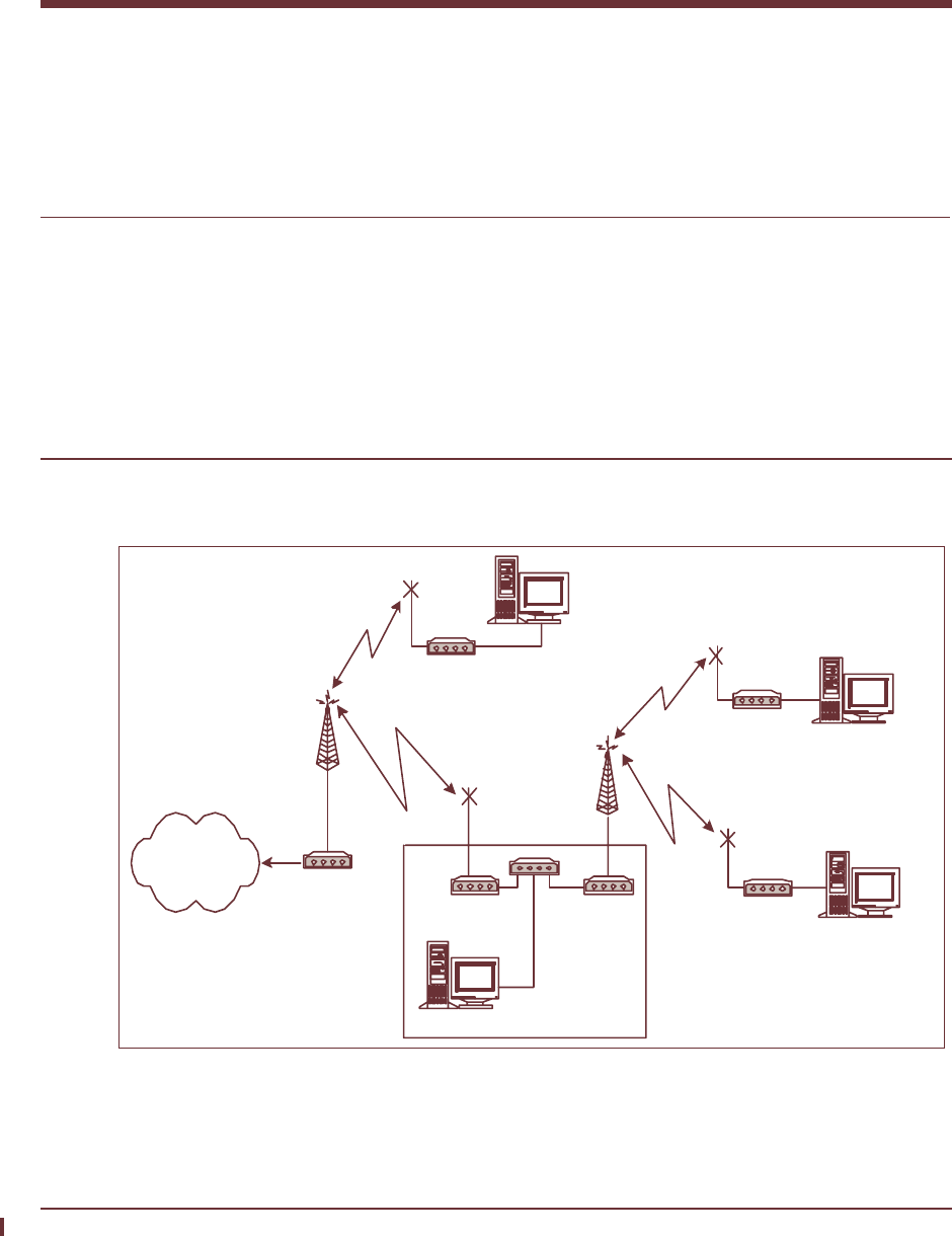
12.1 EUM Thin Route
The EUM Thin Route configuration, in Figure 61, shows how to use an EUM as a thin route to
extend the reach of the LMS4000 900 MHz radio network to a small number of outlying EUMs.
Figure 61 Using an EUM for Thin Route
NOTE: This EUM Thin Route example uses Routed mode. You can also
use Switched Ethernet mode.
CCU2
CAP2
Antenna
CCU1
CAP1
Antenna
Standard
EUM
Thin Route
EUM
Hub
Standard
EUM
Standard
EUM
End-user PC
End-user PC
End-user PC
End-user PC
Radio
Channel "A"
Radio
Channel "B"
178 APCD-LM043-8.0 (DRAFT C)
12: Specialized Applications
In the above configuration, a backhaul is created between the local CCU1 (CAP1) and the
remote CCU2 (CAP2) by deploying an EUM (Thin Route EUM) from CAP1 in CAP2. The Thin
Route EUM will operate at the frequency of CCU1 and have CCU1 as its gateway.
CCU2 may be connected to the Ethernet port of the EUM either directly or through a switch.
Additional subscriber EUMs may then be deployed off CCU2.
To correctly route the traffic between CAP1 and CAP2, routes need to be added to the CAP1
router and CAP1 CCU1. The latter route is required to route the traffic to CCU2.
Traffic traversing from the CAP2 subscribers’ radio network will place additional load on CAP1
CCU1, reducing its available throughput. In order to improve the overall backhaul
performance, a special grade of service (Thin Route GOS) should be provisioned in CAP1
CCU1 and assigned to the Thin Route EUM.
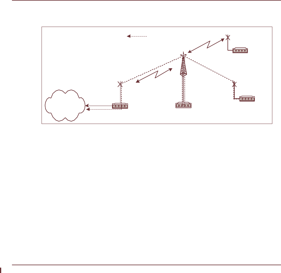
12.2 EUM Backhaul
In some cases, it may be cost-effective to use an EUM as the backhaul link as an alternative to
a separate wired or wireless link to the CCU, as is illustrated in Figure 62.
Figure 62 Using an EUM for Backhaul
The above configuration has one CCU located at a remote location and one EUM (Backhaul)
installed at a NAP or CAP. The CCU’s Ethernet port is unused and may be left unconnected,
or with appropriate routing it may be used for a co-located user PC. The Backhaul EUM’s
Ethernet would typically be connected to a router, switch, or a hub. The subscriber EUMs are
setup as normal.
The Backhaul EUM scenario creates an extended bridged network with Backhaul EUM, CCU,
and subscribers EUMs following the same IP scheme as the rest of the existing network.
The Max Customers setting in the Backhaul EUM applies to the number of hosts on the
Ethernet side of the Backhaul EUM, not to the number of customers served by the CCU.
WaveRider recommends setting Max Customers to 50.
To have a good backhaul performance it is important that the Backhaul EUM is positioned for
optimum RF reception (for example, on a tower).
Backhaul EUM CCU3000
Antenna
EUM
EUM
Data path from end-user
modem to network

12: Specialized Applications
APCD-LM043-8.0 (DRAFT C) 179
Traffic traversing from subscriber computers to the Backhaul EUM will use the radio link twice,
placing additional load on the Backhaul EUM. To alleviate potential performance bottlenecks,
a special grade of service (EUM Backhaul GOS) should be provisioned in the CCU used for
the backhaul configuration and assigned to the Backhaul EUM.
Traffic load considerations in the EUM Backhaul configuration imply that the CCU should
support approximately half the usual number of subscribers, with approximately the same
throughput as usual.
— This page is intentionally left blank —

APCD-LM043-8.0 (DRAFT C) 181
Appendix A Specifications
This appendix lists the following specifications for the LMS4000 900 MHz Radio Network,
specifically the technical specifications for the CCU and EUM, configured for operation in the
FCC/IC RF regulatory domain:
•Radio Specifications on page 181
•Ethernet Interface Specifications on page 182
•Power Supply Specifications on page 182
•Environmental Specifications on page 182
Table 32 Radio Specifications
Maximum Number of Operational CCUs and
Orthogonal Channels 4
Maximum Number of EUMs per CCU 300
Maximum Address Table Size (CCU) 1051
Maximum Bridge Table Size 256
Minimum Channel Center Frequency 905 MHz
Maximum Channel Center Frequency 925 MHz
Channel Bandwidth 5.5 MHz
Center Frequency Spacing Increment 0.2 MHz (101 channels possible)
Minimum Separation Between Co-located
Channels 6.6 MHz
Maximum Co-located Channels 4

182 APCD-LM043-8.0 (DRAFT C)
Appendix A: Specifications
Table 33 Ethernet Interface Specifications
Table 34 Power Supply Specifications
Table 35 Environmental Specifications
Co-located Channel Set Center
Frequencies (standard) 905 MHz, 911.6 MHz, 918.4 MHz, and 925
MHz
Note: Other frequencies can be used,
depending on site-specific considerations.
Contact WaveRider for more information.
Modulation Scheme Based on DSSS (Direct-Sequence Spread
Spectrum) signals, modulated with CCK
(Complementary Code Keying), and Barker-
coded BPSK (Binary Phase Shift Keying)
and QPSK (Quaternary Phase Shift Keying)
Receiver Sensitivity for BER < 10-5 Better than -86 dBm
Maximum Over-the-Air, Raw Data Rate 2.75 Mbps
Maximum Output Power +26 dBm
CCU Physical Interface 10BaseT (Ethernet)
EUM Physical Interface 10BaseT (Ethernet)
AC Input 110/230 ± 15% VAC, single phase
AC Input Frequency 50/60 ± 3 Hz
Maximum Input Current 0.2 A
Operating Temperature 0°C to +50°C, CCU
10°C to +40°C, EUM3000
0°C to +40°C, EUM3003
(10%-80% RH non-condensing)
Storage Temperature -40°C to +70°C

APCD-LM043-8.0 (DRAFT C) 183
Appendix B Factory Configuration
This appendix identifies the factory configuration settings for the CCU and EUM.
Table 36 CCU Factory Configuration
Parameter Default Configuration
Console Prompt The default console prompt is the station
(CCU) ID.
Deregistration Count 8
DHCP Relay Disabled
Ethernet IP Address 192.168.10.250
Ethernet Netmask 24
255.255.255.0
ffffff00
Gateway IP Address 192.168.10.1
GOS Definitions BE (0 - 384 kbps)
Bronze (0 - 1024 kbps)
Silver (128 - 256 kbps)
Gold (256 - 512 kbps)
Denied (0 kbps)
Note: The above data rates are based on
FTP transfers from a single EUM, using
maximum-sized packets.
GOS Default (Authorization Table) BE (Best Effort)
Maximum Associations 75
Maximum Registered EUMs 300
Password By default, the CCU has no password.
Press Enter at the password prompt to
enter a null password.

184 APCD-LM043-8.0 (DRAFT C)
Appendix B: Factory Configuration
Port Filters 137 (both)
138 (both)
139 (both)
445 (both)
1512 (both)
Protocol Switched Ethernet Mode (“Switched”)
Radio Enabled
Radio Frequency 9050 (905.0MHz)
Radio Power +26 dBm (High)
RADIUS Period 60 (minutes)
SNMP Contact WaveRider Communications Inc.
SNMP Location www.waverider.com
SNMP Read Communities public
SNMP Write Communities private
SNMP Traps None entered
SNTP Client Enabled No
SNTP Client Resynchronization Period 3600 seconds
SNTP Client Retry Period 30 seconds
SNTP Relay Enabled Yes
SNTP Relay Send Time on Boot Yes
SNTP Relay Send Time on EUM
Registration Yes
SNTP Servers 132.246.168.148 (time.nrc.ca)
140.162.8.3 (ntp.cmr.gov)
136.159.2.1 (ntp.cpsc.ucalgary.ca)
192.5.5.250 (clock.isc.org)
Statistics Log Interval 15 minutes
Table 36 CCU Factory Configuration
Parameter Default Configuration

Appendix B: Factory Configuration
APCD-LM043-8.0 (DRAFT C) 185
To reset the CCU to factory default
60:03:3a> fi dir
Directory listing:
SA1110.EXE 475764
BASIC.CFG 1992
PORT.CFG 6240
SNTP.CFG 156
ROUTE.CFG 2896
AUTHDB.CFG 3496
DHCP.CFG 896
SA1110.BAK 475764
60:03:3a> fil del basic.cfg
file deleted
60:03:3a> fil del port.cfg
file deleted
60:03:3a> fil del sntp.cfg
file deleted
60:03:3a> fil del route.cfg
file deleted
60:03:3a> fil del authdb.cfg
file deleted
60:03:3a> fil del dhcp.cfg
file deleted
60:03:3a> reset
rebooting CCU ...
(... Power On Self Test ...)
WaveRider Communications, Inc. LMS3000
Password:
60:03:3a> port add 137 both
60:03:3a> port add 138 both
60:03:3a> port add 139 both
60:03:3a> port add 445 both
60:03:3a> port add 1512 both
60:03:3a>
60:03:3a> save
Basic Config saved
Port Filter Config saved
sntp cfg file saved
Route Config saved
Authorization Database saved
DHCP Server Config saved
60:03:3a>
60:03:3a> port
PORT FILTERS
Port Filter
---------------------------------
445 both
137 both
138 both
139 both
1512 both
----------------------------------
60:03:3a>

186 APCD-LM043-8.0 (DRAFT C)
Appendix B: Factory Configuration
Table 37 EUM Factory Configuration
Parameter Default Configuration
Console Prompt The default console prompt is the station
(EUM) ID.
Ethernet IP Address 192.168.10.250
Ethernet Netmask 24
255.255.255.0
ffffff00
Gateway IP Address 192.168.10.1
Maximum Number of Customers 1
Password By default, the EUM has no password.
Press Enter at the password prompt to
enter a null password.
Port Filters 137 (both)
138 (both)
139 (both)
445 (both)
1512 (both)
Radio Enabled
Radio Frequency 9050 (905.0MHz)
Radio Power +26 dBm (High)
SNMP Contact WaveRider Communications Ltd.
SNMP Location www.waverider.com
SNMP Read Communities public
SNMP Write Communities private
SNMP Traps None entered
SNTP Client (listen only) Enabled Yes

Appendix B: Factory Configuration
APCD-LM043-8.0 (DRAFT C) 187
To reset the EUM to factory default
60:ff:fe> fil dir
Directory listing:
BASIC.CFG 1992
SNTP.CFG 156
SA1110.EXE 475764
PORT.CFG 6240
SA1110.BAK 475764
60:ff:fe> fil del basic.cfg
file deleted
60:ff:fe> fil del sntp.cfg
file deleted
60:ff:fe> fil del port.cfg
file deleted
60:ff:fe> reset
rebooting EUM ...
(... Power On Self Test ...)
WaveRider Communications, Inc. LMS3000
Password:
60:ff:fe> port add 137 both
60:ff:fe> port add 138 both
60:ff:fe> port add 139 both
60:ff:fe> port add 445 both
60:ff:fe> port add 1512 both
60:ff:fe>
60:ff:fe> save
Basic Config saved
Port Filter Config saved
sntp cfg file saved
60:ff:fe>
60:ff:fe> port
PORT FILTERS
Port Filter
---------------------------------
445 both
137 both
138 both
139 both
1512 both
----------------------------------
60:03:3a>
— This page is intentionally left blank —

APCD-LM043-8.0 (DRAFT C) 189
Appendix C Command-Line Syntax
This appendix describes the various LMS4000 commands and syntax, and consists of the
following sections:
•Command-line Syntax Conventions and Shortcuts on page 189
•CCU Command-line Syntax on page 191
•EUM Command-line Syntax on page 204
NOTE: The help command on the CCU or EUM may display additional
commands that are not listed in the following tables. WaveRider
recommends that you use only commands listed in this Appendix.
All commands typed at the command-line interface are recorded verbatim in the system log.
For instructions on accessing the command-line interface, refer to Access Interface on page
221.
Command-line Syntax Conventions and Shortcuts
Table 38 shows the typographical conventions used to represent command-line syntax. Table
39 provides a list of shortcuts and methods to get help on commands. To execute a command,
type the command and press Enter.
Table 38 Command-Line Syntax Conventions
Convention Use Examples
monospaced
font
Indicates that you must type the text. ip route

190 APCD-LM043-8.0 (DRAFT C)
Appendix C: Command-Line Syntax
Table 39 Command-Line Shortcuts and Getting Help
Enter Bold face type indicates a keyboard key
press. A plus sign (+) indicates key
combinations. For example, for Ctrl+U,
press and hold down the Ctrl key, then
press the U key.
Enter
Esc
Ctrl+U
<variable> Specifies a variable name or other
information that you must replace with a
real name or value.
ip address ethernet
<ip_address>
bold
characters
Indicates the shortcut characters for a
command.
ip ethernet can also be
typed as i e
| Separates two mutually exclusive choices
in a command. Type one choice and do
not type the vertical bar.
exit|quit
( ) Encloses a range of values from which
you can choose a value.
ip ethernet
<aaa.bbb.ccc.ddd>
(0-32)
Convention Use Examples
Type To do this...
↑ ↓ Scroll up and down through last 10 commands.
?To display the names of the root commands.
<command_name> ? To display the syntax for a command.
help To display all the commands, their subcommands and
the parameters and options for each command.
help <command_name> To display the parameters and options for the
command.
ESC To cancel the command you are typing.

Appendix C: Command-Line Syntax
APCD-LM043-8.0 (DRAFT C) 191
CCU Command-line Syntax
Table 40 CCU Command-Line Syntax
NOTE: In Table 40, commands that are noted with a √ in the right-hand
column will not take effect until you have rebooted the CCU.
Command Syntax (CCU) Command Description
address Displays the Address Table.
address delete|remove <eum_id> Removes an EUM ID from the Address
Table.
• <eum_id> is the EUM ID, in the form
XX:XX:XX.
address flush Removes all entries from the Address
Table.
airDisplays the EUM Registration Table.
air associations Displays the maximum association count.
air associations <value> Changes the maximum number of
associations.
• <value> must be between 1 and 75.
air delete <eum_id> Deletes an EUM from the Registration
Table.
• <eum_id> is the EUM ID, formatted in
hexadecimal XX:XX:XX.
air dereg Displays the deregistration count.
air dereg <value> Changes the deregistration count.
• <value> is the deregistration count,
from 1 to 254.
air fdereg <eum_id> Forces deregistration of an EUM.
• <eum_id> is the EUM ID, in the form
XX:XX:XX.
air flush Removes all entries from the EUM
Registration Table.
arpDisplays the ARP Table.

192 APCD-LM043-8.0 (DRAFT C)
Appendix C: Command-Line Syntax
arp add <aaa.bbb.ccc.ddd>
<XX.XX.XX.XX.XX.XX> [flags]
Adds an entry to the ARP Table.
• <aaa.bbb.ccc.ddd> is the IP
address of the new entry.
• <XX:XX:XX:XX:XX:XX> is the MAC
address, in hexadecimal format.
• [flags] is always set to 4, meaning
the entry is permanent and does not
time out, as long as the CCU or EUM is
ON.
arp delete <aaa.bbb.ccc.ddd> Deletes an entry from the ARP Table:
• <aaa.bbb.ccc.ddd> is the IP
address of the entry being deleted.
arp flush Removes all entries from the ARP Table.
arp map Displays the ARP Map Table.
arp map
<aaa.bbb.ccc.ddd>|<eum_id>
Maps an IP address <aaa.bbb.ccc.ddd> to a
MAC address, EUM ID, grade of service,
etc.
• <aaa.bbb.ccc.ddd> is the IP
address of the host to display.
• <eum_id> is the EUMID of the EUM to
display.
auth Displays the EUM Authorization Table.
auth add | edit <eum_id> <gos> Adds an EUM to the Authorization Table.
• <eum_id> is the EUM ID, in the form
XX:XX:XX.
• <gos> is the EUM grade of service.
Available GOSs are gold, silver, bronze, be
(best effort), and denied.
auth default <gos> Sets the default GOS, which is the GOS
assigned to an EUM upon registration.
• <gos> is the default grade of service.
Available GOSs are gold, silver, bronze, be
(best effort), and denied.
NOTE: After changing the default GOS,
execute the “air flush” and “arp
flush” commands for the default
GOS to apply to EUMs that are
already registered.
auth delete <eum_id> The EUM will receive the default grade of
service.
• <eum_id> is the EUM ID, in the form
XX:XX:XX.
Command Syntax (CCU) Command Description

Appendix C: Command-Line Syntax
APCD-LM043-8.0 (DRAFT C) 193
auth gos <gos> Displays the GOS definitions.
• <gos> is the default grade of service.
Available GOSs are gold, silver, bronze, be
(best effort), and broadcast.
auth radius Displays the RADIUS client configuration.
auth radius accounting enable Enable RADIUS accounting.
NOTE: RADIUS authorization must be
enabled before you can enable RADIUS
accounting.
auth radius accounting disable Disable RADIUS accounting.
auth radius disable Disables RADIUS authorization and
accounting.
auth radius enable Enables RADIUS authorization.
auth radius period <period> Sets the period between RADIUS requests
for each EUM.
• <period> is the number of minutes
between RADIUS requests. The period
must be between 5 and 20000 minutes.
auth radius primary
<aaa.bbb.ccc.ddd>|none
Sets the primary RADIUS server IP address
and password. The CCU prompts for
password entry.
• <aaa.bbb.ccc.ddd> is the primary
RADIUS server IP address.
auth radius secondary
<eee.fff.ggg.hhh>|none
Sets the secondary RADIUS server IP
address and password. The CCU prompts
for password entry.
• <eee.fff.ggg.hhh> is the secondary
RADIUS server IP address.
bcfDisplays the basic configuration file (BCF).
bridge | customer Displays the bridge table.
bridge | customer flush Removes all entries from the bridge table.
bridge | customer maximum <max> Sets the maximum number of customers.
• <max> is the maximum, which must be
from 1 to 50.
dhcp Displays status of CCU DHCP Relay, either
enabled or disable.
dhcp disable Disables DHCP relay.
dhcp enable Enables DHCP relay.
Command Syntax (CCU) Command Description

194 APCD-LM043-8.0 (DRAFT C)
Appendix C: Command-Line Syntax
dhcp relay Displays the CCU DHCP relay status and
contents of the DHCP Server Table.
dhcp relay add <aaa.bbb.ccc.ddd>
<netmask>
Adds the DHCP server IP address.
• <aaa.bbb.ccc.ddd> is the IP
address of the DHCP server.
• <netmask> is the subnet mask of the
DHCP server (0-32).
dhcp relay delete
<aaa.bbb.ccc.ddd> <netmask>
Deletes the DHCP server IP address.
• <aaa.bbb.ccc.ddd> is the IP
address of the DHCP server.
• <netmask> is the subnet mask of the
DHCP server (0-32).
dhcp relay flush Removes all DHCP server IP addresses.
exit|quit Exits the current console session and
returns to the password prompt.
file copy | cp <source>
<destination>
Copies a file.
• <source> is the name of the source
file.
• <destination> is the name of the
destination file.
file delete <filename> Deletes a file.
• <filename> is the name of the file you
want to delete.
file dir | lsLists the name, size, and cyclic redundancy
check (CRC) for each file.
Command Syntax (CCU) Command Description

Appendix C: Command-Line Syntax
APCD-LM043-8.0 (DRAFT C) 195
file get
<aaa.bbb.ccc.ddd>|<EUM_ID>
<username> [<password>|_]
<source> <destination>
NOTE: If you enter only the IP address or
EUM ID, then <username> defaults to
“buywavc”, <source> defaults to “null”, and
<destination> defaults to “null”—the link
speed test.
Retrieves a file from a remote location.
• <aaa.bbb.ccc.ddd> is the IP
address of the computer from which
you are retrieving the file.
NOTE: You can use <EUM_ID> in
place of the IP address for EUMs or
CCUs.
• <username> is the user name required
to log on to the remote computer.
Defaults to “buywavc” if left blank.
• <password> is the password to log on
to the remote computer. If you omit the
password argument, you will be
prompted for the password, which will
be asterisked out and not recorded in
the system log. Use _ when the
password is blank.
• <source> is the path and filename of
the file that is being retrieved from the
remote computer. Defaults to “null” if
left blank.
• <destination> is the path and
filename to which the file will be copied.
Defaults to “null” if left blank.
file mkboot | makeboot
<filename>
Makes a new boot file. Use this command
with caution.
• <filename> is the name of the new
boot file.
file rename | rn <from> <to> Renames a file.
• <from> is the old file name.
• <to> is the new file name.
help Displays the console command structure.
ipDisplays the CCU IP address assignments.
ip ethernet Displays the Ethernet IP address of the
CCU.
NOTE: If the CCU is in Switched Ethernet
mode or Through Only mode, this command
displays the CCU IP address.
Command Syntax (CCU) Command Description

196 APCD-LM043-8.0 (DRAFT C)
Appendix C: Command-Line Syntax
ip ethernet <aaa.bbb.ccc.ddd>
<netmask>
Changes the Ethernet IP address of the
CCU.
• <aaa.bbb.ccc.ddd> is the new
Ethernet IP address of the CCU.
• <netmask> is the subnet mask of the
CCU Ethernet address (0-32).
NOTE: If the CCU is in Switched Ethernet
mode or Through Only mode, this command
sets the CCU IP address.
√
ip gateway Displays the IP address of the router
through which the CCU connects to the
Internet.
ip gateway <aaa.bbb.ccc.ddd> Defines the router through which the CCU
connects to the Internet.
• <aaa.bbb.ccc.ddd> is the new
Ethernet IP address of the router.
√
ip radio Displays the radio IP address of the CCU.
NOTE: If the CCU is in Switched Ethernet
mode or Through Only mode, this command
displays the CCU IP address.
ip radio <aaa.bbb.ccc.ddd>
<netmask>
Changes the radio IP address of the CCU.
• <aaa.bbb.ccc.ddd> is the new IP
address of the CCU radio.
• <netmask> is the subnet mask of the
CCU radio address (0-32).
NOTE: If the CCU is in Switched Ethernet
mode or Through Only mode, this command
sets the CCU IP address.
√
password Initiates the process for changing the
system password.
pcfDisplays the permanent configuration file
(PCF).
Command Syntax (CCU) Command Description

Appendix C: Command-Line Syntax
APCD-LM043-8.0 (DRAFT C) 197
ping <aaa.bbb.ccc.ddd>|<eum_id>
<length> <interval>
Sends ICMP echo requests to a remote
host.
• <aaa.bbb.ccc.ddd> is the IP
address of the remote host.
• <eum_id> is the EUMID (in the form
XX:XX:XX) of an EUM or CCU to ping.
• <length> is an optional parameter
defining the ping packet size in bytes.
The default length is 64 bytes, and the
maximum length is 1460 bytes.
• <interval> is an optional parameter
defining the number of milliseconds
between pings. The interval may be
from 100 to 4000 milliseconds, and the
default is 490 milliseconds.
Press any key to halt.
port Displays the TCP/UDP port filters.
port add <port number>
tcp|udp|both
Adds or modifies a port filter.
• <port number> is the number of the
port to be filtered.
• One of tcp, udp, or both is selected
to filter TCP or UDP messages, or both.
port delete <port number> Deletes a port filter.
• <port number> is the port to be
deleted.
port flush Deletes all port filters.
protocol Displays the protocol mode.
protocol routed|switched|through Changes the protocol mode. √
radio Displays the radio attributes of the CCU.
Command Syntax (CCU) Command Description

198 APCD-LM043-8.0 (DRAFT C)
Appendix C: Command-Line Syntax
radio analyse <samples>
<interval> <start> <stop>
Starts a spectral analysis.
• <samples> is the number of RSSI and
noise floor samples taken at each
frequency. The default value is 200.
• <interval> is the step size between
sample points. The default is 2
(200kHz), which is also the minimum
step size allowed. The maximum
interval is 200 (20MHz).
• <start> is the lowest frequency
sampled, in 100’s of kHz. The default is
9000 (900.0MHz), which is also the
minimum allowed.
• <stop> is the upper boundary on
frequencies sampled, in 100’s of kHz.
The default is 9300 (930.0MHz), which
is also the maximum allowed.
radio analyse last This command will redisplay the results of
the last spectral analysis that was
performed.
radio comment <comment> Adds a comment to both the tabular and the
graphical versions of the spectral analysis
output. The character string that you enter in
<comment> will be displayed below the date
and time line. Up to 50 characters are
allowed.
radio disable Disables the radio transmitter/receiver. The
radio is re-enabled automatically after
rebooting the unit.
NOTE: When using this command, ensure
that an Ethernet or serial port connection to
the CCU is available; otherwise, you will be
unable to re-enable the radio.
radio enable Enables the radio transmitter/receiver.
radio frequency Displays the CCU radio frequency in tenths
of a MHz; for example, 905.0 MHz is
displayed as 9050.
√
radio frequency <frequency> Changes the CCU radio frequency.
• <frequency> is the new radio
frequency, in tenths of a MHz. (For
example, 905.0 MHz is entered as
9050.) The radio frequency must be
within the range of 9050 to 9250. The
frequency may use only 0.2 MHz
increments and may use even values
only.
Command Syntax (CCU) Command Description

Appendix C: Command-Line Syntax
APCD-LM043-8.0 (DRAFT C) 199
radio meter Displays traffic statistics and polling
statistics totals for each grade of service.
radio meter <interval> Displays running average per second traffic
and polling statistics for each grade of
service.
• <interval> in seconds is the time
over which the average is made. Press
any key to halt.
radio rf high|low|<value> Displays or sets the power of the CCU radio,
where programming the value to:
•high will set the transmit power
output to +26 dBm,
•low will set the transmit power to
+15 dBm, and
•<value>, where <value>, an
integer between 15 and 26
inclusive, will set the transmit power
to +<value> dBm.
NOTE: The CCU RF level should normally
be set to high.
radio rssi Displays continuous RSSI readings. Press
any key to halt.
rcfDisplays the contents of the route
configuration file (RCF).
reset|reboot Reboots the CCU.
route Displays the routing table of the CCU.
route add <aaa.bbb.ccc.ddd>
<eee.fff.ggg.hhh> <netmask>
Adds a static route to the routing table.
• <aaa.bbb.ccc.ddd> is the Ethernet
IP address of the network being added
to the routing table.
• <eee.fff.ggg.hhh> is the Ethernet
IP address of the gateway through
which the destination is reached.
• <netmask> is the subnet mask of the
destination network(0-32).
Command Syntax (CCU) Command Description

200 APCD-LM043-8.0 (DRAFT C)
Appendix C: Command-Line Syntax
route delete <aaa.bbb.ccc.ddd>
<eee.fff.ggg.hhh> <netmask>
Deletes a route from the routing table.
• <aaa.bbb.ccc.ddd> is the Ethernet
IP address of the network being
removed from the routing table.
• <eee.fff.ggg.hhh> is the Ethernet
IP address of the gateway through
which the destination device can be
reached.
• <netmask> is the subnet mask for the
destination network (0-32).
route stats Displays the routing statistics.
save | commit Saves configuration changes.
snmp Displays the CCU SNMP information.
snmp community Displays the SNMP communities.
snmp community add <community>
<read|write>
Adds an SNMP community.
• <community> is the name of the
SNMP community being added, from 1-
31 characters in length.
• Enter <read> or <write> to indicate
the type of the community being added.
snmp community delete
<community>
Deletes an SNMP community.
• <community> is the name of the
SNMP community being deleted.
snmp contact Displays the SNMP system contact.
snmp contact <contact> Changes the SNMP system contact.
• <contact> is the name of the contact
(WISP, for example), from 1-80
characters in length.
√
snmp interface Displays the SNMP interface MIBs.
snmp location Displays the SNMP system location. √
snmp location <location> Changes the SNMP system location.
• <location> is the location of the
CCU, from 1-80 characters in length.
snmp trap Displays the SNMP Trap Server Table.
snmp trap add <aaa.bbb.ccc.ddd>
<community>
Adds a trap server community.
• <aaa.bbb.ccc.ddd> is the Ethernet
IP address of the trap server.
• <community> is the community name
for the trap server, from 1-63
characters in length.
Command Syntax (CCU) Command Description

Appendix C: Command-Line Syntax
APCD-LM043-8.0 (DRAFT C) 201
snmp trap delete
<aaa.bbb.ccc.ddd> <community>
Deletes a trap server community.
• <aaa.bbb.ccc.ddd> is the Ethernet
IP address of the trap server.
• <community> is the community name
for the trap server being deleted, from
1-63 characters in length.
stats Displays the statistics for all drivers and
network protocols.
stats auth Displays authorization/RADIUS statistics.
stats clear Clears the statistics for all drivers.
stats ethernet Displays Ethernet statistics.
stats log <interval>|OFF|NOW Displays or sets statistics logging interval in
minutes.
• <interval> is the time interval in minutes
of statistics logging, from 1 to 65535
minutes; setting the interval also turns
logging on.
• OFF turns statistics logging off.
• NOW prints the current statistics to the
log without affecting the period or
turning logging on or off.
stats mac Displays MAC driver statistics.
stats net Displays network protocol statistics.
stats net icmp Displays ICMP statistics.
stats net ip Displays IP statistics.
stats net tcp Displays TCP statistics.
stats net udp Displays UDP statistics.
stats radio Displays radio driver statistics.
stats rp | routing Displays routing protocol statistics.
stats summary Displays a summary of the Atmel MAC
statistics.
sys log <number> <offset> Displays the modem log file.
• <number> is the number of characters
to print from the log file.
• <offset> is the character offset;
default is 0.
sys macDisplays the Atmel MAC log.
sys memory Displays memory allocation information.
Command Syntax (CCU) Command Description

202 APCD-LM043-8.0 (DRAFT C)
Appendix C: Command-Line Syntax
sys prompt <new prompt> Changes the system prompt.
• <new prompt> is the new prompt,
from 1-20 characters in length.
You cannot use the “>” character. It will be
appended to the prompt automatically.
sys ssDisplays the system status file, which
includes POST results, file status, I/O
connections, and system statistics.
sys tasks Displays the task list.
sys uptime Displays the length of time the system has
been running.
NOTE: It rolls over to zero after about 8
days.
sys version Displays software version information.
sys wlog <text> Writes text to the log file. This command is
useful for adding information to the log for
subsequent analysis:
• <text> may be from 1-246 characters
in length.
telnet
<aaa.bbb.ccc.ddd>|<eum_id>
Begins a telnet session to a destination
address.
• <aaa.bbb.ccc.ddd> is the IP address of
a host, such as an EUM, accessible
from this CCU, in the format
aaa.bbb.ccc.ddd.
• <eum_id> is the EUMID (in the form
XX:XX:XX) of an EUM or CCU to
connect to.
time Displays the system calendar clock time.
time client Manages the SNTP client and displays a list
of NTP servers.
time client disable Disables the SNTP client.
time client enable Enables the SNTP client.
time print Prints the SNTP configuration and NTP
server list.
time relay destination
[broadcast|<aaa.bbb.ccc.ddd>]
Relays NTP messages to an EUM network
or to an individual EUM.
• <aaa.bbb.ccc.ddd> is the multicast
address, SNTP client network address,
EUM IP address.
Command Syntax (CCU) Command Description

Appendix C: Command-Line Syntax
APCD-LM043-8.0 (DRAFT C) 203
time relay disable Disables SNTP relay over the radio
interface.
time relay disable boot Disables CCU time updates when the CCU
boots.
time relay disable registration Disables EUM time updates when an EUM
registers with a CCU.
time relay enable Enables SNTP relay over the radio
interface.
time relay period <seconds> Sets the time relay resynchronization
period, in seconds.
• Time period may be from 0 to 100000
seconds.
• Enter 0 to force immediate
resynchronization.
The default time relay period is 3600
seconds.
time server Manages NTP servers.
time server add
<aaa.bbb.ccc.ddd>
Adds or modifies an NTP server.
time server default Restores default NTP servers.
time server delete
<aaa.bbb.ccc.ddd>
Deletes an NTP server.
time server flush Deletes all NTP servers.
time set <time> Sets the system time (Greenwich Mean
Time).
• <time> is formatted [dy-mon-year
hh:mm:ss] or [mm-dd-yy hh:mm:ss}.
This command overwrites the local time
obtained from the NTP server. The local
time will be updated on the next refresh from
the NTP server, unless the time client is
disabled.
time stats Displays time statistics.
watch <eum_id> Gathers link statistics for a specified EUM.
The watch command zeros the statistics
before executing.
watch Displays link statistics previously gathered
for a specific EUM. Note that the watch
command displays only the link statistics for
the EUM connected to this CCU for which
statistics were most recently gathered.
Command Syntax (CCU) Command Description

204 APCD-LM043-8.0 (DRAFT C)
Appendix C: Command-Line Syntax
EUM Command-line Syntax
Table 41 EUM Command-Line Syntax
NOTE: In Table 41, commands that are noted with a √ in the right-hand
column will not take effect until you have rebooted the EUM.
Command Syntax (EUM) Command Description
arpDisplays the ARP Table.
arp add <aaa.bbb.ccc.ddd>
<XX.XX.XX.XX.XX.XX> [flags]
Adds an entry to the ARP Table.
• <aaa.bbb.ccc.ddd> is the IP
address of the new entry.
• <XX:XX:XX:XX:XX:XX> is the MAC
address, in hexadecimal format.
• [flags] is always set to 4, meaning
the entry is permanent and does not
time out, as long as the CCU or EUM is
ON.
arp delete <aaa.bbb.ccc.ddd> Deletes an entry from the ARP table.
• <aaa.bbb.ccc.ddd> is the IP
address of the entry.
arp flush Removes all entries from the ARP Table.
bcfDisplays the basic configuration file (BCF).
bridge | customer Displays the bridge table.
bridge | customer flush Removes all entries from the bridge table.
bridge | customer maximum <max> Sets the maximum number of customers.
• <max> is the maximum, which must be
from 1 to 50.
exit|quit Exits the current console session and
returns to the password prompt.
file copy|cp <source>
<destination>
Copies a file.
• <source> is the name of the source
file.
• <destination> is the name of the
destination file.
file delete <filename> Deletes a file.
• <filename> is the name of the file you
want to delete.
file dir|lsLists the file directory.

Appendix C: Command-Line Syntax
APCD-LM043-8.0 (DRAFT C) 205
file get
<aaa.bbb.ccc.ddd>|<EUM_ID>
<username> [<password>|_]
<source> <destination>
NOTE: If you enter only the IP address or
EUM ID, then <username> defaults to
“buywavc”, <source> defaults to “null”, and
<destination> defaults to “null”—the link
speed test.
Retrieves a file from a remote location.
• <aaa.bbb.ccc.ddd> is the IP
address of the computer from which
you are retrieving the file.
NOTE: You can use <EUM_ID> in
place of the IP address for EUMs or
CCUs.
• <username> is the user name required
to log on to the remote computer.
Defaults to “buywavc” if left blank.
• <password> is the password to log on
to the remote computer. If you omit the
password argument, you will be
prompted for the password, which will
be asterisked out and not recorded in
the system log. Use _ when the
password is blank.
• <source> is the path and filename of
the file that is being retrieved from the
remote computer. Defaults to “null” if
left blank.
• <destination> is the path and
filename to which the file will be copied.
Defaults to “null” if left blank.
file mkboot|makeboot <filename> Makes a new boot file.
• <filename> is the name of the new
boot file.
file rename|rn <from> <to> Renames a file.
• <from> is the old file name.
• <to> is the new file name.
help Displays the console command structure.
ipDisplays the EUM IP address assignments.
ip ethernet Displays the EUM IP address and netmask,
the same for both the radio and Ethernet
port.
Command Syntax (EUM) Command Description

206 APCD-LM043-8.0 (DRAFT C)
Appendix C: Command-Line Syntax
ip ethernet <aaa.bbb.ccc.ddd>
<netmask>
Changes the IP address of the EUM.
• <aaa.bbb.ccc.ddd> is the new IP
address of the EUM.
• <netmask> is the subnet mask of the
EUM IP address (0-32).
√
ip gateway Displays the IP address of the router
through which the EUM connects to the
Internet. In routed mode networks, this is
the IP address of the router.
ip gateway <aaa.bbb.ccc.ddd> Changes the router through which the EUM
connects to the Internet.
• <aaa.bbb.ccc.ddd> is the radio IP
address of the router through which the
EUM connects to the Internet. In routed
mode networks, this is the CCU radio
IP address.
√
password Initiates the process for changing the
system password.
pcfDisplays the permanent configuration file
(PCF).
ping <aaa.bbb.ccc.ddd>|<eum_id>
<length> <interval>
Sends ICMP echo requests to a remote
host.
• <aaa.bbb.ccc.ddd> is the IP
address of the remote host.
• <eum_id> is the EUMID (in the form
XX:XX:XX) of an EUM or CCU to ping.
• <length> is an optional parameter
defining the ping packet size in bytes.
The default length is 64 bytes, and the
maximum length is 1460 bytes.
• <interval> is an optional parameter
defining the number of milliseconds
between pings. The interval may be
from 100 to 4000 milliseconds, and the
default is 490 milliseconds.
Press any key to halt.
port Displays the TCP/UDP port filters.
port add <port number>
tcp|udp|both
Adds or modifies a port filter.
• <port number> is the number of the
port to be filtered.
• One of tcp, udp, or both is selected to
filter TCP or UDP messages, or both.
Command Syntax (EUM) Command Description

Appendix C: Command-Line Syntax
APCD-LM043-8.0 (DRAFT C) 207
port delete <port number> Deletes a port filter.
• <port number> is the port to be
deleted.
port flush Deletes all port filters.
radio Displays the radio attributes of the EUM.
radio analyse <samples>
<interval> <start> <stop>
Starts a spectral analysis.
• <samples> is the number of RSSI and
noise floor samples taken at each
frequency. The default value is 200.
• <interval> is the step size between
sample points. The default is 2
(200kHz), which is also the minimum
step size allowed. The maximum
interval is 200 (20MHz).
• <start> is the lowest frequency
sampled, in 100’s of kHz. The default is
9000 (900.0MHz), which is also the
minimum allowed.
• <stop> is the upper boundary on
frequencies sampled, in 100’s of kHz.
The default is 9300 (930.0MHz), which
is also the maximum allowed.
radio analyse last This command will redisplay the results of
the last spectral analysis that was
performed.
radio comment Adds a comment to both the tabular and the
graphical versions of the spectral analysis
output.
radio disable Disables the radio transmitter/receiver. The
radio is re-enabled automatically after
rebooting the unit.
NOTE: When using this command, ensure
that an Ethernet connection to the EUM is
available; otherwise, you will be unable to
re-enable the radio.
radio enable Enables the radio transmitter/receiver.
radio frequency Displays the EUM radio frequency in tenths
of a MHz; for example, 905.0 MHz is
displayed as 9050.
Command Syntax (EUM) Command Description

208 APCD-LM043-8.0 (DRAFT C)
Appendix C: Command-Line Syntax
radio frequency <frequency> Changes the EUM radio frequency.
• <frequency> is the new radio
frequency, in tenths of a MHz. (For
example, 905.0 MHz is entered as
9050.) The radio frequency must be
within the range of 9050 to 9250. The
frequency may use only 0.2 MHz
increments and may use even values
only.
√
radio rc Clears the RSSI, SQ, RNA, and RNB
histograms.
radio rf high|low|<value> Displays or sets the power of the EUM
radio, where programming the value to:
•high will set the transmit power
output to +26 dBm,
•low will set the transmit power to
+15 dBm, and
•<value>, where <value>, an
integer between 15 and 26
inclusive, will set the transmit power
to +<value> dBm.
NOTE: The EUM RF level should normally
be set to high.
radio rh Displays the RSSI, SQ, RNA, and RNB
histograms.
radio rssi Displays continuous RSSI readings. Press
any key to halt.
reset|reboot Reboots the EUM.
route Displays the routing table for the EUM.
route stats Displays the routing statistics.
save|commit Saves configuration changes.
snmpDisplays the EUM SNMP information.
snmp community Displays the SNMP communities.
snmp community add <community>
<read|write>
Adds an SNMP community.
• <community> is the name of the
SNMP community being added, from 1-
31 characters in length.
• Enter <read> or <write> to indicate
the type of the community being added.
Command Syntax (EUM) Command Description

Appendix C: Command-Line Syntax
APCD-LM043-8.0 (DRAFT C) 209
snmp community delete
<community>
Deletes an SNMP community.
• <community> is the name of the
SNMP community being deleted.
snmp contact Displays the SNMP system contact.
snmp contact <contact> Changes the SNMP system contact.
• <contact> is name of the EUM SNMP
system contact (subscriber, for
example), from 1-80 characters in
length.
√
snmp interface Displays the interface MIBs.
snmp location Displays the SNMP system location.
snmp location <location> Changes the SNMP system location.
• <location> is the location of the
EUM, from 1-80 characters in length.
√
snmp trap Displays the SNMP Trap Server Table.
snmp trap add <aaa.bbb.ccc.ddd>
<community>
Adds a trap server community.
• <aaa.bbb.ccc.ddd> is the Ethernet
IP address of the trap server.
• <community> is the community name
for the trap server, from 1-63
characters in length.
snmp trap delete
<aaa.bbb.ccc.ddd> <community>
Deletes a trap server community.
• <aaa.bbb.ccc.ddd> is the Ethernet
IP address of the trap server.
• <community> is the community name
for the trap server being deleted, from
1-63 characters in length.
stats Displays the statistics for all drivers and
network protocols.
stats clear Clears the statistics for all drivers.
stats ethernet Displays Ethernet statistics.
stats log <interval>|OFF|NOW Displays or sets statistics logging interval in
minutes.
• <interval> is the time interval in minutes
of statistics logging, from 1 to 65535
minutes; setting the interval also turns
logging on.
• OFF turns statistics logging off.
• NOW prints the current statistics to the
log without affecting the period or
turning logging on or off.
Command Syntax (EUM) Command Description

210 APCD-LM043-8.0 (DRAFT C)
Appendix C: Command-Line Syntax
stats mac Displays MAC driver statistics.
stats net Displays network protocol statistics.
stats net icmp Displays ICMP statistics.
stats net ip Displays IP statistics.
stats net tcp Displays TCP statistics.
stats net udp Displays UDP statistics.
stats radio Displays radio driver statistics.
stats rp|routing Displays routing protocol statistics.
stats summary Displays a summary of the Atmel MAC
statistics.
sys log <number> <offset> Displays the modem log file.
• <number> is the number of characters
to print from the log file.
• <offset> is the character offset,
default is 0.
sys macDisplays the Atmel MAC log.
sys memory Displays memory allocation information.
sys prompt <new prompt> Changes the system prompt.
• <new prompt> is the new prompt,
from 1-20 characters in length.
You cannot use the “>” character. It will be
appended to the prompt automatically.
sys ssDisplays the system status file, which
includes POST results, file status, I/O
connections, and system statistics.
sys task Displays the task list.
sys uptime Displays system uptime.
sys version Displays software version information.
sys wlog <text> Writes text to the log file. This feature is
useful for adding information to the log for
subsequent analysis.
• <text> may be from 1-246 characters
in length.
time Displays the system calendar clock time.
time client Manages the SNTP client and displays a list
of NTP servers.
time client disable Disables the SNTP client.
Command Syntax (EUM) Command Description

Appendix C: Command-Line Syntax
APCD-LM043-8.0 (DRAFT C) 211
time client enable Enables the SNTP client.
time print Prints the SNTP configuration and NTP
server list.
time set <time> Sets the system time (Greenwich Mean
Time).
• <time> is formatted [dy-mon-year
hh:mm:ss] or [mm-dd-yy hh:mm:ss}.
This command overwrites the local time
obtained from the NTP server. The local
time will be updated on the next refresh from
the NTP server, unless the time client is
disabled.
time stats Displays time statistics.
Command Syntax (EUM) Command Description

212 APCD-LM043-8.0 (DRAFT C)
Appendix C: Command-Line Syntax

APCD-LM043-8.0 (DRAFT C) 213
Appendix D INOP Commands
If CCU or EUM software becomes inaccessible or corrupted, the unit will start in inoperative
mode (INOP). You can also force an EUM3003 to start in INOP mode to recover an EUM if the
IP address is not known. While in INOP mode, CCUs and EUMs use a subset of the regular
CLI commands. For instructions on putting an EUM3003 into INOP mode, refer to EUM3003
INOP Button on page 224. These INOP commands are described in the following tables.
NOTE: The radio is not functional while in INOP mode.
Table 42 CCU INOP
NOTE: In Table 42, commands that are noted with a √ in the right-hand
column will not take effect until you have rebooted the CCU.
Command Syntax (CCU) Command Description
bcfDisplays the basic configuration file (BCF).
exit|quit Exits the current console session and
returns to the password prompt.
file copy | cp <source>
<destination>
Copies a file.
• <source> is the name of the source
file.
• <destination> is the name of the
destination file.
file delete <filename> Deletes a file.
• <filename> is the name of the file you
want to delete.
file dir | lsLists the name, size, and cyclic redundancy
check (CRC) for each file.

214 APCD-LM043-8.0 (DRAFT C)
Appendix D: INOP Commands
file get
<aaa.bbb.ccc.ddd>|<EUM_ID>
<username> [<password>|_]
<source> <destination>
NOTE: If you enter only the IP address or
EUM ID, then <username> defaults to
“buywavc”, <source> defaults to “null”, and
<destination> defaults to “null”—the link
speed test.
Retrieves a file from a remote location.
• <aaa.bbb.ccc.ddd> is the IP
address of the computer from which
you are retrieving the file.
NOTE: You can use <EUM_ID> in
place of the IP address for EUMs or
CCUs.
• <username> is the user name required
to log on to the remote computer.
Defaults to “buywavc” if left blank.
• <password> is the password to log on
to the remote computer. If you omit the
password argument, you will be
prompted for the password, which will
be asterisked out and not recorded in
the system log. Use _ when the
password is blank.
• <source> is the path and filename of
the file that is being retrieved from the
remote computer. Defaults to “null” if
left blank.
• <destination> is the path and
filename to which the file will be copied.
Defaults to “null” if left blank.
file mkboot | makeboot
<filename>
Makes a new boot file. Use this command
with caution.
• <filename> is the name of the new
boot file.
file rename | rn <from> <to> Renames a file.
• <from> is the old file name.
• <to> is the new file name.
help Displays the console command structure.
ipDisplays the CCU IP address assignments.
ip ethernet Displays the Ethernet IP address of the
CCU.
Command Syntax (CCU) Command Description

Appendix D: INOP Commands
APCD-LM043-8.0 (DRAFT C) 215
ip ethernet <aaa.bbb.ccc.ddd>
<netmask>
Changes the Ethernet IP address of the
CCU.
• <aaa.bbb.ccc.ddd> is the new
Ethernet IP address of the CCU.
• <netmask> is the subnet mask of the
CCU Ethernet address (0-32).
√
ip gateway Displays the IP address of the router
through which the CCU connects to the
Internet.
ip gateway <aaa.bbb.ccc.ddd> Defines the router through which the CCU
connects to the Internet.
• <aaa.bbb.ccc.ddd> is the new
Ethernet IP address of the router.
√
ip radio Displays the radio IP address of the CCU.
ip radio <aaa.bbb.ccc.ddd>
<netmask>
Changes the radio IP address of the CCU.
• <aaa.bbb.ccc.ddd> is the new IP
address of the CCU radio.
• <netmask> is the subnet mask of the
CCU radio address (0-32).
√
password Initiates the process for changing the
system password.
pcfDisplays the permanent configuration file
(PCF).
ping <aaa.bbb.ccc.ddd>|<eum_id>
<length> <interval>
Sends ICMP echo requests to a remote
host.
• <aaa.bbb.ccc.ddd> is the IP
address of the remote host.
• <eum_id> is the EUMID (in the form
XX:XX:XX) of an EUM or CCU to ping.
• <length> is an optional parameter
defining the ping packet size in bytes.
The default length is 64 bytes, and the
maximum length is 1460 bytes.
• <interval> is an optional parameter
defining the number of milliseconds
between pings. The interval may be
from 100 to 4000 milliseconds, and the
default is 490 milliseconds.
Press any key to halt.
radio Displays the radio attributes of the CCU.
radio frequency Displays the CCU radio frequency in tenths
of a MHz; for example, 905.0 MHz is
displayed as 9050.
Command Syntax (CCU) Command Description

216 APCD-LM043-8.0 (DRAFT C)
Appendix D: INOP Commands
Table 43 EUM INOP CLI
In Table 43, commands that are noted with a √ in the right-hand column will not take effect
until you have rebooted the EUM.
radio frequency <frequency> Changes the CCU radio frequency.
• <frequency> is the new radio
frequency, in tenths of a MHz. (For
example, 905.0 MHz is entered as
9050.) The radio frequency must be
within the range of 9050 to 9250. The
frequency may use only 0.2 MHz
increments and may use even values
only.
√
radio rf high|low|<value> Displays or sets the power of the CCU radio,
where programming the value to:
•high will set the transmit power
output to +26 dBm,
•low will set the transmit power to
+15 dBm, and
•<value>, where <value>, an
integer between 15 and 26
inclusive, will set the transmit power
to +<value> dBm.
NOTE: The CCU RF level should normally
be set to high.
reset|reboot Reboots the CCU.
save | commit Saves configuration changes.
Command Syntax (CCU) Command Description
Command Syntax (EUM) Command Description
bcfDisplays the basic configuration file (BCF).
exit|quit Exits the current console session and
returns to the password prompt.
file copy|cp <source>
<destination>
Copies a file.
• <source> is the name of the source
file.
• <destination> is the name of the
destination file.
file delete <filename> Deletes a file.
• <filename> is the name of the file you
want to delete.

Appendix D: INOP Commands
APCD-LM043-8.0 (DRAFT C) 217
file dir|lsLists the file directory.
file get
<aaa.bbb.ccc.ddd>|<EUM_ID>
<username> [<password>|_]
<source> <destination>
NOTE: If you enter only the IP address or
EUM ID, then <username> defaults to
“buywavc”, <source> defaults to “null”, and
<destination> defaults to “null”—the link
speed test.
Retrieves a file from a remote location.
• <aaa.bbb.ccc.ddd> is the IP
address of the computer from which
you are retrieving the file.
NOTE: You can use <EUM_ID> in
place of the IP address for EUMs or
CCUs.
• <username> is the user name required
to log on to the remote computer.
Defaults to “buywavc” if left blank.
• <password> is the password to log on
to the remote computer. If you omit the
password argument, you will be
prompted for the password, which will
be asterisked out and not recorded in
the system log. Use _ when the
password is blank.
• <source> is the path and filename of
the file that is being retrieved from the
remote computer. Defaults to “null” if
left blank.
• <destination> is the path and
filename to which the file will be copied.
Defaults to “null” if left blank.
file mkboot|makeboot <filename> Makes a new boot file.
• <filename> is the name of the new
boot file.
file rename|rn <from> <to> Renames a file.
• <from> is the old file name.
• <to> is the new file name.
help Displays the console command structure.
ipDisplays the EUM IP address assignments.
ip ethernet Displays the EUM IP address and netmask,
the same for both the radio and Ethernet
port.
Command Syntax (EUM) Command Description

218 APCD-LM043-8.0 (DRAFT C)
Appendix D: INOP Commands
ip ethernet <aaa.bbb.ccc.ddd>
<netmask>
Changes the IP address of the EUM.
• <aaa.bbb.ccc.ddd> is the new IP
address of the EUM.
• <netmask> is the subnet mask of the
EUM IP address (0-32).
√
ip gateway Displays the IP address of the router
through which the EUM connects to the
Internet. In routed mode networks, this is
the IP address of the router.
ip gateway <aaa.bbb.ccc.ddd> Changes the router through which the EUM
connects to the Internet.
• <aaa.bbb.ccc.ddd> is the radio IP
address of the router through which the
EUM connects to the Internet. In routed
mode networks, this is the CCU radio
IP address.
√
password Initiates the process for changing the
system password.
pcfDisplays the permanent configuration file
(PCF).
ping <aaa.bbb.ccc.ddd>|<eum_id>
<length> <interval>
Sends ICMP echo requests to a remote
host.
• <aaa.bbb.ccc.ddd> is the IP
address of the remote host.
• <eum_id> is the EUMID (in the form
XX:XX:XX) of an EUM or CCU to ping.
• <length> is an optional parameter
defining the ping packet size in bytes.
The default length is 64 bytes, and the
maximum length is 1460 bytes.
• <interval> is an optional parameter
defining the number of milliseconds
between pings. The interval may be
from 100 to 4000 milliseconds, and the
default is 490 milliseconds.
Press any key to halt.
radio Displays the radio attributes of the EUM.
radio frequency Displays the EUM radio frequency in tenths
of a MHz; for example, 905.0 MHz is
displayed as 9050.
Command Syntax (EUM) Command Description

Appendix D: INOP Commands
APCD-LM043-8.0 (DRAFT C) 219
radio frequency <frequency> Changes the EUM radio frequency.
• <frequency> is the new radio
frequency, in tenths of a MHz. (For
example, 905.0 MHz is entered as
9050.) The radio frequency must be
within the range of 9050 to 9250. The
frequency may use only 0.2 MHz
increments and may use even values
only.
√
radio rf high|low|<value> Displays or sets the power of the EUM
radio, where programming the value to:
•high will set the transmit power
output to +26 dBm,
•low will set the transmit power to
+15 dBm, and
•<value>, where <value>, an
integer between 15 and 26
inclusive, will set the transmit power
to +<value> dBm.
NOTE: The EUM RF level should normally
be set to high.
reset|reboot Reboots the EUM.
save|commit Saves configuration changes.
Command Syntax (EUM) Command Description
— This page is intentionally left blank —

APCD-LM043-8.0 (DRAFT C) 221
Appendix E Access Interface
There are up to three different access interfaces available on CCUs and EUMs. Table 44
below identifies which access interfaces are available on each device type.
Table 44 CCU and EUM Access Interfaces
Telnet Connection
You can use Telnet to connect to a CCU or an EUM from a PC. Two different types of Telnet
connections are possible:
• Local Telnet Session—The PC and the target CCU or EUM are on the same Ethernet
segment and IP subnet. For example, you may connect an Ethernet cable directly
between them.
NOTE: In Switched Ethernet mode, with multiple subnets, the end-user
PC and EUM may not be on the same IP subnet, so the session
would be remote even though they are on the same Ethernet
segment.
• Remote Telnet Session—The PC and the target CCU or EUM are connected by an IP
network. For example, you may be connecting from the PC to the CCU or EUM over
the radio link.
Access Interface CCU3000 EUM3000 EUM3003
Local Telnet Session Available Available Available
Remote Telnet Session Available Available Available
Serial Port Session Available Available Not Available

222 APCD-LM043-8.0 (DRAFT C)
Appendix E: Access Interface
Procedures for both types of Telnet sessions are explained below.
To Connect to a Local CCU or EUM with Telnet
1. Open a Command Prompt window. (For instructions on opening a command prompt
window, please refer to your operating system documentation.)
2. Connect a crossover Ethernet cable with ferrite bead between the PC and CCU or
EUM.
3. Change the IP address of the PC, so the PC and CCU or EUM are on the same
subnet. For more information about configuring PC IP settings, refer to To Configure
PC Network Settings (Windows XP Operating System) on page 226.
TIP: If you do not know the IP address and netmask of the CCU
or EUM, connect to the unit through a serial port and use the “ip
ethernet” command (for CCUs and EUM3000s), or use the
INOP button (for EUM3003s). The default IP address for an
EUM is 192.168.10.250 /24.
4. At the prompt, type telnet aaa.bbb.ccc.ddd and press Enter. (aaa.bbb.ccc.ddd
is the IP Ethernet address of the CCU or EUM.)
WaveRider Communications, Inc. LMS3000
Password:
5. At the password prompt, type the device password and press Enter.
NOTE: The default password for CCUs and EUMs is blank, so press
Enter.
60:ff:fe>
You are now connected to the CCU or EUM with a Telnet session, and you may issue
CLI commands to the device at the command prompt.
To Connect to a Remote CCU or EUM with Telnet
1. Open a Command Prompt window. (For instructions on opening a command prompt
window, please refer to your operating system documentation.)
2. If you are using Routed mode, ensure there is a route between the PC and the target
CCU or EUM. If the PC is connected by Ethernet to the CCU, and you are connecting
to a remote EUM, you must add a route to the radio subnet. For instructions on adding
a route, refer to To Add a Route on a PC on page 227.
TIP: If you do not know the IP address of an EUM, but you
know the EUM ID and can access the CCU, you can Telnet to
the CCU and check the ARP MAP table.

Appendix E: Access Interface
APCD-LM043-8.0 (DRAFT C) 223
3. At the prompt, type telnet aaa.bbb.ccc.ddd and press Enter. (aaa.bbb.ccc.ddd
is the IP Ethernet address of the CCU or EUM.)
WaveRider Communications, Inc. LMS3000
Password:
4. At the password prompt, type the device password and press Enter.
NOTE: The default password for CCUs and EUMs is carriage return.
60:ff:fe>
You are now connected to the CCU or EUM with a Telnet session, and you may issue
CLI commands to the device at the command prompt.
Serial Port Connection
To Connect to a CCU3000 or EUM3000 Through a Serial Port
1. Connect and RS-232, DB9 male to DB9 female, straight-through cable between the
console ports on the CCU3000 or EUM3000 and the PC.
2. Open a terminal emulation program, such as Tera Term Pro or HyperTerminal.
NOTE: You can download Tera Term Pro from WaveRider Technical
Support.
3. Connect to the device using the port settings shown in Table 45.
Table 45 Serial Port Settings
4. At the password prompt, type the device password and press Enter.
NOTE: The default password for CCUs and EUMs is carriage return.
You are now connected to the CCU or EUM with a Serial Port session, and you may
issue CLI commands to the device at the command prompt.
Bits per second 9600
Data bits 8
Parity None
Stop bits 1
Flow Control None

224 APCD-LM043-8.0 (DRAFT C)
Appendix E: Access Interface
EUM3003 INOP Button
NOTE: If you are trying to determine an EUM’s IP address, the gratuitous
ARP feature provides an alternative to using the INOP button.
The EUM transmits a “gratuitous” ARP (an ARP for its own IP
address) two seconds after power up. This gratuitous ARP can
be used to determine the IP address of an EUM if it is not already
known. The operator can either sniff the ARP packet on the
Ethernet interface, or look in the ARP table of a connected host.
The EUM3003 includes an Inoperative Mode (INOP) button. It is a recessed push button on
the connector end of the EUM. Use a paperclip or a small flat screw driver to push the button
gently. You will hear a soft click noise.
The INOP button provides the following functionality:
• Enables you to temporarily reset the IP address to 192.168.10.250 / 24 (Gateway
192.168.10.251).
• Allows for error recovery if the EUM3003 fails during the startup sequence (including a
corrupt boot line).
NOTE: The INOP button is NOT a RESET button. Pushing the INOP
button during normal operation will not reboot the unit.
CAUTION: The radio interface is not functional in INOP mode.
Using the INOP Button to Recover the IP Address
The EUM3003 may be reset to a default IP address by pressing the INOP button.
To Recover the EUM3003 IP Address
1. During the EUM30003 power up cycle, press the INOP button, hold it until the front
three LEDs flash, and then release the INOP button.
The unit starts in INOP Mode, with the IP Address set to 192.168.10.250 /24.
2. Ensure that the PC connected to the EUM3003 is on Ethernet subnet 192.168.10.0 /
24. If not, change the PC network settings. For instructions on changing the PC
network settings, refer to To Configure PC Network Settings (Windows XP Operating
System) on page 226.
NOTE: Restarting an EUM3003 in INOP Mode will not change the IP
address displayed in the BCF.
3. Open a Telnet session to the EUM3003. For instructions, refer to Telnet Connection
on page 221.

Appendix E: Access Interface
APCD-LM043-8.0 (DRAFT C) 225
4. At the prompt, type bcf and press Enter.
WaveRider Communications, Inc. LMS3000
Password:
InOp> bcf
Basic Cfg File:
File ID : basic.cfg
File Time Stamp:
File Version : 5
File Notes : Operator updated
File CRC : 0xE1
IP Address: 192.168.10.250 / 24
IP Subnet : 192.168.10.0 ( 255.255.255.0 )
Gateway IP Address: 192.168.10.1
Contact: WaveRider Communications Inc.
Location: www.waverider.com
Name: LMS3000
SNMP Read Communities:
public
SNMP Write Communities:
private
SNMP Traps:
Statistics Log Interval: 15 minutes
Radio Frequency: 9050
RF Power: LOW
Maximum Number of Customers: 1
InOp>
5. Note the IP settings in the BCF.
6. Type
reset and press Enter.
The EUM3003 is now functioning with its previous IP configuration.
Using the INOP Button When You Cannot Connect to an EUM3003
The EUM3003 may come up in the INOP Mode if the startup fails due to a corrupt boot
sequence or other problem. INOP Mode resets the IP address to the default setting of
192.168.10.250 /24.
To Use the INOP Button
1. From a PC on the 192.168.10.0 /24 subnet, attempt to connect to the EUM3003
through a local Telnet connection.
2. If the connection is successful
a. At the prompt, type ip and press Enter.
60:ff:fe> ip
Ethernet IP Address: 192.168.10.100
Ethernet Net Mask : ffffff00
Gateway IP Address: 192.168.10.1
60:ff:fe>
b. At the prompt, type file dir and press Enter.
60:ff:fe> file dir
Filename Size CRC
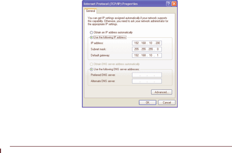
226 APCD-LM043-8.0 (DRAFT C)
Appendix E: Access Interface
SA1110.BAK 0 1d6523d1
BASIC.CFG 1992 1fd3b0ba
PORT.CFG 6240 c7148a64
SA1110.EXE 477617 9af8566b
BOOTROM.BIN 447864 b4fb30fe
SNTP.CFG 156 c771acf9
c. Look for problems, such as an executable file with a size of 0, which indicates
a corrupted file.
3. If the connection is unsuccessful, restart the EUM30003 in INOP mode, as described
in To Recover the EUM3003 IP Address on page 224.
4. If you still cannot connect to the EUM3003, contact WaveRider Technical Support.
PC Configuration
The following two procedures explain how to configure network settings on a PC running the
Windows XP operating system, and how to add a static route to a PC.
To Configure PC Network Settings (Windows XP Operating System)
1. Click the Windows Start button and open Control Panel > Network Connections >
Local Area Connection.
2. Click the
Properties button.
3. Select
Internet Protocol (TCP/IP) and click the Properties button.
4. Select
Use the following IP address.
5. Fill in the IP address, Subnet mask, and Default gateway fields, so the PC is on the
same subnet as the EUM, and click OK.
Figure 63 Windows XP TCP/IP Properties

Appendix E: Access Interface
APCD-LM043-8.0 (DRAFT C) 227
To Add a Route on a PC
1. On the PC, open a command prompt window.
2. At the prompt, type route add aaa.bbb.ccc.ddd mask eee.fff.ggg.hhh
iii.jjj.kkk.lll and press Enter.
• aaa.bbb.ccc.ddd is the radio subnet
• eee.fff.ggg.hhh is the radio subnet mask
• iii.jjj.kkk.lll is the gateway to the radio subnet (Ethernet IP address of the CCU)

228 APCD-LM043-8.0 (DRAFT C)
Appendix E: Access Interface

APCD-LM043-8.0 (DRAFT C) 229
Appendix F Antenna Guidelines
WARNING!
Antennas and associated transmission cable must be
installed by qualified personnel, and external antennas must
be properly grounded. WaveRider assumes no liability for
failure to adhere to this recommendation or to recognized
general safety precautions.
The CCU and EUM have been certified for use with Omni, Patch, Yagi, and Dipole Reflector
antenna types, in addition to the WaveRider Diversity Antenna. Table 46 includes examples of
each of the recommended antenna types, as well as their associated maximum antenna
gains.
Table 46 CCU, EUM Supported Antennas
Antenna system gain is the net gain of the system. In other words, it is the antenna gain minus
the insertion loss due to cabling, connectors, filters, surge protectors, and other hardware
components. During installation, you must verify that the antenna system does not exceed the
maximum allowable certified antenna system gain, which is 8.8 dBi.
Calculate the antenna system gain by adding the value of the insertion loss for each
component of the antenna system, excluding the antenna, and subtracting the total of that
sum from the antenna gain. You can measure the insertion loss of the components, and the
Antenna Type Maximum Antenna Gain
Omni 5.1dBi
Patch 8.5dBi
Yagi 13.0dBi
Panel 12.0dBi

230 APCD-LM043-8.0 (DRAFT C)
Appendix F
antenna gain, at the frequency of interest, or obtain it by referencing the manufacturer’s
supplied literature.
WaveRider Guidelines for outdoor installation are:
• select a cable of type and length so that cable loss is 3.5dB, including connectors.
• use a surge protector, which has about 0.1 db loss,
• use a WaveRider jumper cable to connect the modem to the exterior cable or surge
protector. The jumper cable has a loss of 1 dB.
For example, with a Yagi antenna system, 15m of cable, a surge protector, and a jumper
cable (from modem to surge protector), you would calculate the following antenna system
gain:
• Antenna Gain: 13.0dBi
• Insertion loss:
• External Cable: - 3.5dB
• Surge Protector: - 0.1dB
• Jumper Cable: - 1.0dB
•- 4.6dBi
The antenna gain (13.0dBi) minus the total insertion loss (4.6dBi), yields an antenna system
gain of 8.4dBi, which is a valid antenna configuration, because the antenna system gain is
lower than the maximum permissible value of 8.8 dBi.
WARNING!
To prevent equipment damage, you must use the WaveRider
proprietary WCM connector to connect transmission line and
antennas to the EUM3000.
WARNING!
Use of an outdoor antenna with the EUM requires
professional installation, in accordance with FCC guidelines.
WARNING!
Antennas used with the EUM must not present a short to
ground at the EUM antenna port. Contact the WaveRider
Customer Support Centre for more information.

APCD-LM043-8.0 (DRAFT C) 231
Appendix G CCU/EUM Data Tables
The CCU and EUM firmware is structured around a set of tables and files, which are
discussed in the following sections in the logical order that they are actively involved in the
transmission of packets from the Internet to the end-user’s PC:
•Port Filter Table (CCU and EUM) on page 231
•Routing Table (CCU and EUM) on page 232
•ARP Table (CCU and EUM) on page 236
•Address Translation Table (CCU only) on page 238
•Authorization Table (CCU only) on page 239
•Registration Table (CCU only) on page 240
•ARP Map Table (CCU only) on page 241
•Bridge Table (EUM or CCU in Switched Ethernet or Through Only Mode) on page 242
•Basic Configuration File (CCU and EUM) on page 243
•Permanent Configuration File (CCU and EUM) on page 245
•System Status File (CCU and EUM) on page 246
Port Filter Table (CCU and EUM)
The Port Filter Table provides a list of all port filters that have been enabled. Any IP packet
with one of these port numbers will be discarded.
The contents of the Port Filter Table are:

232 APCD-LM043-8.0 (DRAFT C)
Appendix G: CCU/EUM Data Tables
Table 47 Port Filter Table Entries
To access the Port Filter Table:
60:03:3a> port
PORT FILTERS
Port Filter
---------------------------------
445 both
137 both
138 both
139 both
1512 both
----------------------------------
60:03:3a>
Routing Table (CCU and EUM)
The Routing Table is used by the CCU to determine the routing of IP packets. The routes in
the Routing Table are either entered by the system operator as static routes, or automatically
generated by the CCU. The CCU does not support dynamic routing.
NOTE: With a CCU in Switched Ethernet mode or Through Only mode,
or with an EUM, these routes apply only to packets originated by
the EUM or CCU application. Additional routes can only be added
to a CCU in Routed mode.
The Routing Table contains the following three routes:
Table Entry Description
Port The number of the port which is to be filtered.
Filter For each port listed, the CCU or EUM can be set to filter UDP, TCP,
or both UDP and TCP packets.

Appendix G: CCU/EUM Data Tables
APCD-LM043-8.0 (DRAFT C) 233
Table 48 Basic Routes
In addition to these standard routes, the system operator may add other routes; for example,
routes to support direct CCU-to-CCU communications, without going back to the NAP router.
Each route in the Routing Table has the following entries:
Table 49 Routing Table Entries
Default Route
Any packet with a destination not listed in the Routing Table is forwarded
to the gateway address defined in the default route. Normally, this is be
the IP address of the NAP router. The CCU or EUM generates the default
route automatically when you enter the gateway IP address.
Radio Subnet
Route
Any packet with a destination in the radio subnet (EUMs, end-user PCs)
is forwarded to the CCU radio port. The CCU or EUM generates this
route automatically, using the CCU radio subnet IP address.
Loopback
Route
The loopback interface exists (among other reasons) so the CCU
operating system can talk to itself without handing the packet to a
hardware driver. This route keeps unneeded traffic off the network. The
CCU or EUM generates this loopback route automatically.
Entry Description
Destination The IP address for the destination network.
Mask The subnet mask for the destination network.
TOS
Type of service, for example:
• 0000 Default
• 0001 Minimize monetary cost
• 0010 Maximize reliability
• 0100 Maximize throughput
• 1000 Minimize delay
RFC1700 and RFC1349 recommend TOS settings for various protocols,
including Telnet, FTP, TFTP, ICMP and SNMP.
Gateway The IP address of the gateway through which to access the destination
network.
Flags Refer to Table 50.
RefCnt
Number of processes currently referencing the route. If a process requires
a route, it looks it up in the Routing Table. When the route is being
referenced by a process, refcnt will be incremented by one. When the
process is done with the route, refcnt will be decremented by one.

234 APCD-LM043-8.0 (DRAFT C)
Appendix G: CCU/EUM Data Tables
To view the Routing Table:
WaveRider Communications, Inc. LMS3000
Password:
60:03:3a> route
Destination Mask TOS Gateway Flags RefCnt Use Interface
Proto
0.0.0.0 0 0 192.168.1.1 3 0 67 esmc0 1
127.0.0.1 0 0 127.0.0.1 5 1 30 lo0 0
192.168.10.0 ffffff00 0 192.168.10.1 101 0 0 rdr1 0
60:03:3a>
60:03:3a>
In the above example, the default route is defined by:
Destination Mask TOS Gateway Flags RefCnt Use Interface Proto
0.0.0.0 0 0 10.0.0.1 803 0 196587 esmc0 1
Any IP packet with a destination which is not listed in the Routing Table will be forwarded
through the Ethernet port and on to the NAP router (IP address 10.0.0.1).
The radio subnet route is defined by:
Destination Mask TOS Gateway Flags RefCnt Use Interface Proto
10.5.0.0 ffff0000 0 10.5.0.1 101 0 0 rdr1 0
Any IP packet destined for the radio subnet (any IP address starting with 10.5.xx.xx) will be
forwarded through the CCU radio port (IP address 10.5.0.1) and over the radio link to the
EUMs and end-user’s computers.
The loopback route is defined by:
Destination Mask TOS Gateway Flags RefCnt Use Interface Proto
127.0.0.1 0 0 127.0.0.1 5 0 24 lo0 0
Any IP packet destined for 127.0.0.1, which is an IP address reserved for loopback, will be
looped back to the CCU operating system.
The Routing Table flags are summarized in Table 50.
Use Initialized to 0 and incremented every time an IP datagram uses this route.
Interface
The CCU interface through which to send packets to the gateway and
destination, one of:
• esmc0: CCU Ethernet interface
• rdr1: CCU radio interface
• lo0: Loopback
Proto This entry is an operating system parameter that has no meaning for CCU
configuration and operation.
Entry Description

Appendix G: CCU/EUM Data Tables
APCD-LM043-8.0 (DRAFT C) 235
Table 50 Routing Table Flags.
To use Table 50, consider the flag associated with the default route, 803, which is equal to
(800 + 2 +1). Referring to Table 50, this route was manually added, the destination is a
gateway, and the route is usable.
With the CCU in routed mode, you can display the routing configuration file by entering rcf in
the CCU command line:
60:02:xx> rcf
File ID : route.cfg
File Time Stamp:
File Version :
File Notes : Default File - Auto Created
File CRC : 0xDE
Routing Table:
Destination Address: 172.24.8.0
Gateway Address : 192.168.10.1
Destination Mask : ffffffff
TOS : 0
Flags : 0
Destination Address: 172.24.11.255
Gateway Address : 192.168.10.1
Destination Mask : ffffffff
TOS : 0
Flags : 0
The above example shows a routing table to which two routes have been manually added.
Flag Mask Description
0x1
0x2
0x4
0x8
0x10
0x20
0x40
0x80
0x100
0x200
0x400
0x800
0x1000
0x2000
0x4000
0x8000
Route usable
Destination is a gateway
Host entry (net otherwise)
Host or net unreachable
Created dynamically (by redirect)
Modified dynamically (by redirect)
Message confirmed
Subnet mask present
Generate new routes on use
External daemon resolves name
Generated by ARP or ESIS
Manually added
Just discard packets (during updates)
Protocol specific routing flag
Protocol specific routing flag
Modified by management protocol

236 APCD-LM043-8.0 (DRAFT C)
Appendix G: CCU/EUM Data Tables
ARP Table (CCU and EUM)
For each host (EUM, PC, or router) in the system, the ARP (Address Resolution Protocol)
Table displays the following information:
Table 51 ARP Table Entries
The ARP Table is automatically built by the CCU or EUM based on traffic passing between the
Ethernet and Radio ports. This table displays the host IP and MAC addresses. After the CCU
or EUM recovers the destination IP address from an IP packet sent to the router layer, it looks
in the ARP Table to find the destination Ethernet MAC address. If the IP address does not
appear in the ARP Table, the CCU or EUM obtains the MAC address through an ARP request/
reply and adds it to the ARP Table. The only time a host IP address appears in the ARP Table,
is if the host has recently (in the past ten minutes or so) sent or received data. This can be
forced using a ping, Telnet, SNMP request, or by entering arp map <aaa.bbb.ccc.ddd>,
where <aaa.bbb.ccc.ddd> is the host IP address.
To View the CCU ARP MAP table:
60:03:3a> arp map 192.168.10.250
IP Address Ethernet EUMID GOS Last Rx
192.168.10.250 00:90:c8:60:ff:fe 60:ff:fe bronze-61 1
60:03:3a>
OR:
60:03:3a> arp map
ARP MAP TABLE
IP Address Ethernet EUMID GOS RSSI[dBm] Last Rx
5.11.1.101 00:10:a4:c2:10:bb 60:00:6b be -48 100
Table Entry Description
destination Host IP Address
gateway Host Ethernet MAC Address
flags The only valid flag is 4.
Refcnt
Number of processes currently referencing this ARP entry. If a process
requires a MAC address, it looks it up in the ARP Table. When the ARP
entry is referenced by a process, refcnt will be incremented by one.
When the process is done with the ARP entry, refcnt will be
decremented by one.
Use Number of times the ARP Table has been accessed for this network
element.
Interface
The type of interface, one of the following:
• esmc0: Ethernet
• rdr1: Radio
• lo0: Loopback

Appendix G: CCU/EUM Data Tables
APCD-LM043-8.0 (DRAFT C) 237
5.11.1.102 ee:ee:ee:37:02:03 60:00:04 be -53 0
5.11.1.103 ee:ee:ee:37:02:04 60:02:08 be -54 0
5.11.1.104 ee:ee:ee:37:01:01 60:06:b6 be -47 0
5.11.1.105 ee:ee:ee:37:01:02 60:06:9d be -47 0
5.11.1.106 ee:ee:ee:37:01:03 60:06:a4 be -47 0
5.11.1.107 ee:ee:ee:37:01:04 60:0a:99 be -48 0
60:03:3a>

238 APCD-LM043-8.0 (DRAFT C)
Appendix G: CCU/EUM Data Tables
To view the CCU ARP table:
60:03:3a> arp
LINK LEVEL ARP TABLE
destination gateway flags Refcnt Use Interface
--------------------------------------------------------------------------
10.0.0.1 00:30:80:4a:08:a1 405 1 5 esmc0
10.0.0.2 00:10:4b:6c:fa:54 405 0 4610 esmc0
10.0.0.3 00:90:27:33:c7:e8 405 0 507 esmc0
10.0.0.10 00:a0:98:00:9b:26 405 0 1 esmc0
10.0.0.15 00:10:83:fd:61:a 405 0 781 esmc0
10.0.0.16 00:10:83:fd:e1:4e 405 0 1839 esmc0
10.0.0.17 00:b0:d0:e1:04:c0 405 0 155 esmc0
10.0.1.68 00:00:e8:4d:62:3 405 1 19054 esmc0
10.5.1.17 00:50:da:bb:d1:de 405 0 135 rdr1
10.5.2.50 00:50:ba:b3:97:cd 405 0 12 rdr1
10.5.2.54 00:50:da:b7:25:2f 405 0 8823 rdr1
--------------------------------------------------------------------------
60:03:3a>
Address Translation Table (CCU only)
The Address Translation Table lists the MAC addresses for:
• End-user PC’s that have been granted air access, if the CCU has sent traffic to, or
received traffic from, the PC
• EUMs, if the CCU has sent traffic to, or received traffic from, the network element.
If no traffic has been sent traffic to, or received traffic from, an end-user PC or EUM host for a
12-hour period, they will be removed from the Address Translation Table.
The CCU uses the Address Translation Table, which is built automatically by the CCU, to look
up the EUM ID for a particular MAC address. The MAC addresses associated with the EUM,
are:
• EUM Ethernet MAC Address
• End-user PC MAC Address (one or more)
To view the Address Translation Table:
60:03:3a> add
EUM ID MAC Address Time[s]
-------------------------------------
60:00:83 00:90:c8:60:00:83 106
60:00:83 00:d0:b7:69:94:b1 40
Total of 2 entries
60:03:3a>
In the above view, the following MAC addresses are associated with EUM ID 60:00:83:
•00:90:c8:60:00:83 EUM Ethernet MAC Address

Appendix G: CCU/EUM Data Tables
APCD-LM043-8.0 (DRAFT C) 239
•00:d0:b7:69:94:b1 End-user PC MAC Address
Authorization Table (CCU only)
The Authorization Table controls the EUMs’ access to the LMS4000 900 MHz Radio Network.
The Authorization Table contains the grade of service class for each EUM in the system,
whether the EUM is registered or not.
The contents of the Authorization Table are used by the Polling MAC algorithm, and also by
the CCU, to automatically build the Registration Table.
The entries in the Authorization Table can be entered directly by you, or the complete table
can be modified remotely and downloaded to the CCU using FTP. The GOS class entry will
either be a grade of service class, or “denied” (service).
The Default entry in the Authorization Table is assigned on registration to any EUM that has
not been assigned a grade of service class. The Default entry can be a grade of service class,
or denied, meaning any EUM that has not been assigned a grade of service class will be
denied service. This rule applies only to newly registered EUMs, and not to EUMs that have
been previously registered. Once you have changed the default, if you want the default
changed for all EUMs, regardless of when they registered, then you must flush the
Registration Table. The new default then takes effect as the EUMs re-register.
There are two approaches to managing the Authorization Table:
• Approach 1: If the default is set to denied, then EUMs will be denied service unless
they are explicitly entered in the Authorization Table, with a grade of service.
• Approach 2: If the default is set to a grade of service, such as best effort, then EUMs
will be authorized and given a best effort grade of service unless they are explicitly
denied service in the Authorization Table.
NOTE: If the CCU RADIUS Client is enabled, any EUM authorized
through RADIUS is marked as a "radius" entry. An authorization
entry made through the CLI is marked as "static" and is be
updated by RADIUS.
To view the Authorization Table:
60:03:3a> auth
EUM ID GOS CLASS TYPE
-----------------------------------
60:05:13 gold radius
60:08:60 be radius
Default denied
Total of 2 entries
60:03:3a>

240 APCD-LM043-8.0 (DRAFT C)
Appendix G: CCU/EUM Data Tables
Registration Table (CCU only)
The Registration Table contains a list of all registered EUMs. The CCU automatically builds
and adds to this table as EUMs communicate with the CCU. Every EUM that registers with the
CCU appears in this table. The EUM will be removed from the Registration Table if the:
• EUM has not communicated with the CCU for more than 12 hours because:
• the EUM has been turned off for more than 12 hr., or
• the EUM has had no traffic to send for more than 12 hr., or
• the EUM has lost its RF connection to the CCU for more than 12 hr.
• EUM does not respond to traffic from the CCU. In this case, the EUM will be removed
immediately from the Registration Table.
The Registration Table contains the following entries:
Table 52 Registration Table Entries
NOTE: The Rx-Octets, Rx-Packets, Tx-Octets, and Tx-Packets statistics
are identical to the RADIUS accounting statistics and may be
considered the appropriate usage statistics for billing purposes.
Table Entry Description
EUM ID EUM ID
GOS Class Grade of Service Class
RSSI (dBm) Radio received signal strength (RSSI) in dBm of the EUM.
SQ Signal quality, measured at the same time as the RSSI is
recorded.
RNA (dB) Difference between the RSSI and the measured noise
floor.
Time (s) Time since the last payload was received from the EUM.
Rx-Octets Number of octets received from this EUM in data payloads,
including Ethernet header but not radio MAC header.
Rx-Packets Number of Ethernet packets received from this EUM in
data payloads.
Tx-Octets Number of octets sent to this EUM in data payloads,
including Ethernet header but not radio MAC header.
Tx-Packets Number of Ethernet packets sent to this EUM in data
payloads.
Maximum Associations The maximum number of EUMs that can be associated at
any one instant in time.
Deregistration Count An EUM will be de-registered if it does not respond after
the CCU has sent it this many consecutive polls.

Appendix G: CCU/EUM Data Tables
APCD-LM043-8.0 (DRAFT C) 241
The end of the air table also prints the total number of EUMs registered.
To view the Registration Table:
60:03:3a> air
Maximum Associations: 75
Deregistration Count: 8
REGISTERED EUMs
EUM ID GOS RSSI SQ RNA Time Rx-Octets Rx-Packets Tx-Octets Tx-Packets
Class dBm dB s
-------------------------------------------------------------------------------
60:05:13 gold -50 7 59 6 721564 6610 435914 6236
60:08:60 be -47 7 62 32 360842 3318 226746 3224
2 EUMs registered of 300 allowed
60:03:3a>
NOTE: The air command has been used to view the Registration
Table, because reg is too close to reb (reboot).
ARP Map Table (CCU only)
For each host (EUM or PC) in the system, the ARP Map Table displays the following entries:
Table 53 ARP MAP Table Entries
The ARP MAP Table is built automatically by the CCU, from information contained in the
Address, ARP and Registration Tables. Its primary use is to summarize the information in
these tables in a user-friendly format, for presentation to the system operator.
To view the ARP MAP Table:
Table Entry Description
IP Address Host IP address
Ethernet Host Ethernet MAC address
EUMID EUM ID
GOS EUM Grade of Service
RSSI RSSI in dBm of the last payload received from the EUM.
SQ Signal quality, measured at the same time as the RSSI is recorded.
RNA (dB) Difference between the RSSI and the measured noise floor.
Last Rx Number of seconds since the last payload was received from the
EUM.

242 APCD-LM043-8.0 (DRAFT C)
Appendix G: CCU/EUM Data Tables
60:03:3a> arp map 192.168.10.250
IP Address Ethernet EUMID GOS Last Rx
192.168.10.250 00:90:c8:60:ff:fe 60:ff:fe bronze-61 1
60:03:3a>
OR:
60:03:3a> arp map
ARP MAP TABLE
IP Address Ethernet EUMID GOS RSSI[dBm] Last Rx
5.11.1.101 00:10:a4:c2:10:bb 60:00:6b be -48 100
5.11.1.102 ee:ee:ee:37:02:03 60:00:04 be -53 0
5.11.1.103 ee:ee:ee:37:02:04 60:02:08 be -54 0
5.11.1.104 ee:ee:ee:37:01:01 60:06:b6 be -47 0
5.11.1.105 ee:ee:ee:37:01:02 60:06:9d be -47 0
5.11.1.106 ee:ee:ee:37:01:03 60:06:a4 be -47 0
5.11.1.107 ee:ee:ee:37:01:04 60:0a:99 be -48 0
60:03:3a>
Bridge Table (EUM or CCU in Switched Ethernet or Through
Only Mode)
The primary purpose of the Bridge Table is to determine which Ethernet destination addresses
are on the Ethernet side, ensuring local traffic is kept local.
The following points apply to the Bridge Table on an EUM only:
• The Bridge Table also gives you control over the number of PCs that can access the
Internet through the EUM. The Bridge Table is optimized for the case where multiple
hosts are connected to the EUM, but only one accesses the Internet at any given time.
• The Bridge Table presents a list of the end-user computers that are connected to the
EUM. If customer_max is set to “1”, only one of the computers in the table will have air
access. If customer_max is set to “n”, up to “n” computers in the Bridge Table will
have air access.
• Air access is assigned on a “first come, first served” basis. If n=1, the first computer to
transmit packets will be granted air access. All other computers will be denied air
access. If the computer that has been granted air access, does not transmit traffic for
10 minutes, then his air access will be removed and the next computer that transmits
a packet will be granted air access.
• More generally, for any “n”, up to customer_max, the first n computers transmitting
packets will be granted air access and, if any of them fails to transmit traffic for 10
minutes, their air access will be removed, allowing the next computer without air
access to be granted air access as soon as they transmit data.
NOTE: The Bridge Table may contain a maximum of 256 entries.

Appendix G: CCU/EUM Data Tables
APCD-LM043-8.0 (DRAFT C) 243
Table 54 Bridge Table Entries
NOTE: If customer max is set to 1, and you want to connect a different
PC to the EUM, for maintenance purposes, for example, you
must clear the Bridge Table, reset the EUM, and wait 10 minutes.
To display the Bridge Table:
60:03:3a> cust
MAC Address Air Access Time[s]
-------------------------------------------
00:50:da:b7:34:f3 Y 100
00:50:da:bb:d1:de N 100
Total of: 2 entries
Basic Configuration File (CCU and EUM)
The Basic Configuration File (BCF) presents a summary of CCU and EUM configurable
parameters, which are either the factory default settings, or those entered by the system
operator. The BCFs for the CCU and EUM are slightly different, as shown in the examples
below.
EUM BCF
60:ff:fe> bcf
Basic Cfg File:
File ID : basic.cfg
File Time Stamp:
File Version : 5
File Notes : Operator updated
File CRC : 0xE1
IP Address: 192.168.10.250 / 24
IP Subnet : 192.168.10.0 ( 255.255.255.0 )
Gateway IP Address: 192.168.10.1
Contact: WaveRider Communications Inc.
Location: www.waverider.com
Name: LMS3000
Table Entry Description
MAC Address Computer’s MAC address
Air Access
(EUM Only) Y - computer has been granted air access.
N - computer has not been granted air access
Time (s) Time, in seconds, since the last packet was received from a particular
end-user computer or device.

244 APCD-LM043-8.0 (DRAFT C)
Appendix G: CCU/EUM Data Tables
SNMP Read Communities:
public
SNMP Write Communities:
private
SNMP Traps:
Statistics Log Interval: 15 minutes
Radio Frequency: 9050
RF Power: LOW
Maximum Number of Customers: 1
60:ff:fe>
CCU BCF
60:06:4e> bcf
Basic Cfg File:
File ID : basic.cfg
File Time Stamp:
File Version : 5
File Notes : Operator updated
File CRC : 0x7B
CCU in Switched Ethernet Mode
IP Address: 172.16.6.1 / 22
IP Subnet : 172.16.4.0 ( 255.255.252.0 )
Gateway IP Address: 172.16.6.10
Contact: WaveRider
Location: test
Name: LMS3000
SNMP Read Communities:
readtest
SNMP Write Communities:
writetest
SNMP Traps:
192.168.60.7 traptest
Radius Authentication Enabled, Period: 60
Radius Accounting is Enabled
Radius Primary Server : 192.168.60.96
Radius Secondary Server:
Statistics Log Interval: 15 minutes
Radio Frequency: 9184
RF Power: HIGH
Max EUMs allowed to be Registered: 300
Deregistration Count: 8
Maximum Associations: 75
DHCP Disabled

Appendix G: CCU/EUM Data Tables
APCD-LM043-8.0 (DRAFT C) 245
Permanent Configuration File (CCU and EUM)
The Permanent Configuration File (PCF) is a record of device parameters that are
permanently programmed during manufacturing.
CCU PCF
60:03:3a> pcf
Permanent Cfg File:
File ID : perm.cfg
File Time Stamp: 14May2001
File Version : 002
File Notes : Based on TN040
Hardware ID: 4B
Ethernet MAC Address: 00:90:c8:e0:03:3a
Airlink MAC Address: 00:90:c8:60:03:3a
Serial Number: E0033A
Modem Type: CCU
RF level +27 dbm +15 dbm
Lo - 905.0 Mhz -10 28
Med - 915.0 Mhz -26 20
High - 925.0 Mhz -22 20
RSSI level -76 dbm -70 dbm -46 dbm
Lo - 905.0 Mhz 44 50 74
Med - 915.0 Mhz 44 50 74
High - 925.0 Mhz 44 50 74
POT Settings: Wiper1: 121 Wiper2: 127
60:03:3a>
EUM PCF
60:ff:fe> pcf
Permanent Cfg File:
File ID : perm.cfg
File Time Stamp: 8Oct2002
File Version : 003
File Notes : Default File - Auto Created
File CRC : 0xBE
Ethernet MAC Address: 00:90:c8:e0:ff:fe
Hardware ID: 4B
Airlink MAC Address: 00:90:c8:60:ff:fe
Serial Number: E0301F

246 APCD-LM043-8.0 (DRAFT C)
Appendix G: CCU/EUM Data Tables
Modem Type: EUM
RF level +27 dbm +15 dbm
Lo - 905.0 Mhz -2 28
Med - 915.0 Mhz -2 20
High - 925.0 Mhz -2 20
RSSI level -76 dbm -70 dbm -46 dbm
Lo - 905.0 Mhz 44 50 74
Med - 915.0 Mhz 44 50 74
High - 925.0 Mhz 44 50 74
POT Settings: Wiper1: 50 Wiper2: 100
60:ff:fe>
System Status File (CCU and EUM)
The System Status File is a record of the results of the CCU and EUM POST (Power On Self
Test).
To view the System Status File, type sys ss at the command prompt, and press Enter.
CCU SYS SS
60:03:3a> sys ss
POST Results:
-----------------------
Registers......Passed
Timers.........Passed
SDRAM..........Passed
Watchdog.......Passed
TFFS...........Passed
Ethernet.......Passed
MAC............Passed
USB............Not run
RS232_1........Not run
RS232_2........Not run
File Status:
-----------------------
perm.cfg........Opened-OK
basic.cfg.......Opened-OK
route.cfg.......Opened-OK
sa1110.exe......Opened-OK
authdb.cfg......Opened-OK
IO Connections:
-----------------------
USB Detected...........True
Ethernet Detected......True
RS232_1 Detected.......True
RS232_2 Detected.......False
System State:
-----------------------

Appendix G: CCU/EUM Data Tables
APCD-LM043-8.0 (DRAFT C) 247
System.........Operational
Hardware Rev...A
60:03:3a>
EUM3003 SYS SS
60:ff:fe> sys ss
POST Results:
-----------------------
Registers......Passed
Timers.........Passed
SDRAM..........Passed
Watchdog.......Passed
TFFS...........Passed
Ethernet.......Passed
MAC............Passed
USB............Not run
RS232_1........Not run
RS232_2........Not run
File Status:
-----------------------
perm.cfg........Opened-OK
basic.cfg.......Opened-OK
route.cfg.......Test Not Run
sa1110.exe......Opened-OK
authdb.cfg......Test Not Run
IO Connections:
-----------------------
USB Detected...........False
Ethernet Detected......True
RS232_1 Detected.......False
RS232_2 Detected.......False
System State:
-----------------------
System.........Operational
Hardware Rev...B
60:ff:fe>

248 APCD-LM043-8.0 (DRAFT C)
Appendix G: CCU/EUM Data Tables

APCD-LM043-8.0 (DRAFT C) 249
Appendix H Windows Ping
Commands
The following table lists the options available for use with a Windows Ping test. This
information was obtained from Microsoft Windows 2000 TCP/IP Protocols and Services
Technical Reference, pp. 184-185.
Table 55 Windows Ping Test Command Options
Option Use Default
-t Sends Echoes until interrupted. Not set
-a Performs a Domain Name System (DNS) reverse query to
resolve the DNS hose name of the specified IP address Not set
-n count The number of Echoes to send 4
-l size The size of the Optional Data field up to a maximum of
65,500 32
-f Sets the Don’t Fragment (DF) flag to 1 Not set
-I TTL Sets the value of the TTL field in the IP header 32
-v TOS Sets the value of the Type of Service field in the IP header.
The TOS value is in decimal 0
-r count Sends the ICMP Echoes using the IP Record Route option
and sets the value of the number of slots. Count has a
maximum value of 9.
Not set
-s count Sends the ICMP Echoes using the IP Internet Timestamp
option and sets the value of the number of slots. Count
has a maximum value of 4. Windows 2000 PING uses the
Internet Timestamp FLAG set to 1 (records both the IP
addresses of each hop and the timestamp.
Not set

250 APCD-LM043-8.0 (DRAFT C)
Appendix H: Windows Ping Commands
-j host-list Sends the ICMP Echoes using the Loose Source Route option
and sets the next hop addresses to the IP addresses in the host
list. The host list is made up of IP addresses separated by spaces
corresponding to the loose source route. There can be up to nine
IP addresses in the lost list.
Not set
-k host-list Sends the ICMP Echoes using the Strict Source Route option and
sets the next hop addresses to the IP addresses in the host list.
The host list is made of IP addresses in the host list. The host list
is made of IP addresses separated by spaces corresponding to
the loose source route. There can be up to 9 IP addresses in the
host list.
Not set
-w timeout Waits the specified amount of time, in milliseconds, for the
corresponding Echo Reply before displaying a Request Timed
Out message.
1000
Option Use Default

APCD-LM043-8.0 (DRAFT C) 251
Appendix I SNMP MIB Definitions
This appendix defines the MIBs used in the CCU and EUM. These MIBs are organized under
the following headings:
•MIB-II Elements Supported from RFC-1213 on page 251
•WaveRider CCU Enterprise MIBs on page 255
•CCU RFC MIB-II Traps on page 266
•WaveRider EUM Enterprise MIBs on page 267
•EUM RFC MIB-II Traps on page 276
MIB-II Elements Supported from RFC-1213
The CCU and EUM support the following MIB-II groups, which are defined in detail in
RFC1213.
Groups in MIB-II
MIB-II is divided into the following MIBs. All values in Table 56 are prefixed by 1.3.6.1.2.1.
Table 56 Groups in MIB-II
MIB Name OID Type Status Description
system 1 MIB R This group provides information on the general system, such as
system description, contact, system up time.
interfaces 2 MIB R This group has one set of values for each interface on the
modem. The CCU/EUM has 3 interfaces: 1= loopback, 2 =
esmc0 (ethernet) and 2 = mdr1 (radio).

252 APCD-LM043-8.0 (DRAFT C)
Appendix I: SNMP MIB Definitions
at 3 MIB R This group shows the address translation table, mapping
Ethernet addresses to IP addresses. This group is only for MIB-
I compatibility.
ip 4 MIB R This group provides all of the statistics on IP traffic that is routed
through the modem. For EUMs, all traffic from the end-user to
the CCU bypass the IP stack in the EUM so these numbers are
only for the EUM applications. For the CCU, all IP traffic through
the CCU router application, including CCU application traffic.
icmp 5 MIB R This groups provides statistics on all ICMP packets processed
by the IP stack.
tcp 6 MIB R This provides counters for all TCP packets processed by the
modem. Only TCP packets sent or received by the modem
applications are counted (e.g. FTP or Telnet sessions directly to
the modem) since any packets for other hosts are routed by the
IP protocol and never reach the TCP protocol.
udp 7 MIB R Counters for all UDP packets processed by the modem's
applications. Only UDP packets sent or received by the modem
applications are counted (e.g. FTP or Telnet sessions directly to
the modem) since any packets for other hosts are routed by the
IP protocol and never reach the UDP protocol.
snmp 11 MIB R Counters for all SNMP packets process by the modem's
applications.
MIB Name OID Type Status Description

Appendix I: SNMP MIB Definitions
APCD-LM043-8.0 (DRAFT C) 253
Interfaces Group MIB
Table 57 provides the details of the Interfaces group MIB mentioned above. All values in the
following table are prefixed with 1. 3. 6.1. 2.1. 2.
Table 57 MIB-II Interface List Header MIB
All values in Table 58 are prefixed with 1.3.6.1.2.1.2.2.1, as defined in RFC1213, and are read
only.
Table 58 MIB-II Interface List Table MIB
MIB Name OID Type Status Description
ifIndex 1 Integer R The number of entries in ifTable.
ifTable 2 MIB The list of interfaces.
MIB Name OID Value Type Accepted Values Description
ifIndex 1 Integer A unique value for each interface. Its
value ranges between 1 and the value of
ifNumber. The value for each interface
must remain constant at least from one
re-initialization of the entity's network
management system to the next re-
initialization.
ifDescr 2 String lo0: loopback
esmc0: ethernet
mdr1: radio
A textual string containing information
about the interface. This string should
include the name of the manufacturer,
the product name and the version of the
hardware interface.
ifType 3 Integer 6:ethernet-csmacd
6: radio interface
24: softwareLoopback
The type of interface, distinguished
according to the physical/link protocol(s)
immediately `below' the network layer in
the protocol stack. The radio interface
and ethernet-csmacd return the same
value since they are both viewed as
Ethernet ports by the CCU routing
application.
ifMtu 4 Integer The size of the largest datagram which
can be sent/received on the interface,
specified in octets. For interfaces that are
used for transmitting network datagrams,
this is the size of the largest network
datagram that can be sent on the
interface.
ifSpeed 5 Gauge An estimate of the interface's current
bandwidth in bits per second. For
interfaces which do not vary in bandwidth
or for those where no accurate estimation
can be made, this object should contain
the nominal bandwidth.

254 APCD-LM043-8.0 (DRAFT C)
Appendix I: SNMP MIB Definitions
ifPhysAddress 6 Phys
Address
The interface's address at the protocol
layer immediately `below' the network
layer in the protocol stack. For interfaces
which do not have such an address (e.g.,
a serial line), this object should contain
an octet string of zero length.
ifAdminStatus 7 Integer 1: up
2: down
3: testing
The desired state of the interface. The
testing(3) state indicates that no
operational packets can be passed.
ifOperStatus 8 Integer 1: up
2: down
3: testing
The current operational state of the
interface. The testing(3) state indicates
that no operational packets can be
passed.
ifLastChange 9 TimeTicks The value of sysUpTime at the time the
interface entered its current operational
state. If the current state was entered
prior to the last re-initialization of the local
network management subsystem, then
this object contains a zero value.
ifInOctets 10 Counter The total number of octets received on
the interface, including framing
characters.
ifInUcastPkts 11 Counter The number of subnetwork-unicast
packets delivered to a higher-layer
protocol.
ifInNUcastPkts 12 Counter The number of non-unicast (i.e.,
subnetwork-broadcast or subnetwork-
multicast) packets delivered to a higher-
layer protocol.
ifInDiscards 13 Counter The number of inbound packets which
were chosen to be discarded even
though no errors had been detected to
prevent their being deliverable to a
higher-layer protocol. One possible
reason for discarding such a packet could
be to free up buffer space.
ifInErrors 14 Counter The number of inbound packets that
contained errors preventing them from
being deliverable to a higher-layer
protocol.
ifInUnknownProt
os
15 Counter The number of packets received through
the interface which were discarded
because of an unknown or unsupported
protocol.
ifOutOctets 16 Counter The total number of octets transmitted
out of the interface, including framing
characters.
ifOutUcastPkts 17 Counter The total number of packets that higher-
level protocols requested be transmitted
to a subnetwork-unicast address,
including those that were discarded or
not sent.
MIB Name OID Value Type Accepted Values Description
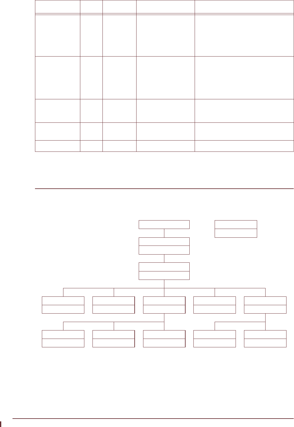
Appendix I: SNMP MIB Definitions
APCD-LM043-8.0 (DRAFT C) 255
WaveRider CCU Enterprise MIBs
The structure of the CCU MIBs is illustrated in Figure 64.
Figure 64 CCU MIBs
Each of the MIBs in Figure 64 is discussed in the following sections.
ifOutNUcastPkts 18 Counter The total number of packets that higher-
level protocols requested be transmitted
to a non-unicast (i.e., a subnetwork-
broadcast or subnetwork-multicast)
address, including those that were
discarded or not sent.
ifOutDiscards 19 Counter The number of outbound packets which
were chosen to be discarded even
though no errors had been detected to
prevent their being transmitted. One
possible reason for discarding such a
packet could be to free up buffer space.
ifOutErrors 20 Counter The number of outbound packets that
could not be transmitted because of
errors.
ifOutQLen 21 Gauge The length of the output packet queue (in
packets).
ifSpecific 22 object Not used
MIB Name OID Value Type Accepted Values Description
WaveRider (2979)
waverider
ccuGlobal
ccu3000pmacglob
ccuRadioConfig
ccu3000pmacradcfg
ccuRadioStats
ccu3000pmacrs
ccuEtherStats
ccu3000pmaces
ccuModem
ccu3000pmacmodem
ccuRadioStatsGeneral
ccu3000pmacrsgen
ccuRadioStatsDriver
ccu3000pmacrsdrv
ccuRadioStatsAtmel
ccu3000pmacrsatmel
ccuRegistration
ccu3000pmacreg
ccuAuthorization
ccu3000pmacauth
Enterprise (1.3.6.1.4.1)
LMS3000 CCU
ccu3000pmac
MIB Name
MIB File Prefix
Legend

256 APCD-LM043-8.0 (DRAFT C)
Appendix I: SNMP MIB Definitions
CCU Base MIB
All values in Table 59, which are read only, are prefixed with 1. 3. 6.1.4.1. 2979.11.
Table 59 WaveRider CCU Base MIB
CCU General Information Group
All values in Table 60 are prefixed with 1.3.6.1.4.1.2979.11.1.
Table 60 WaveRider CCU General Information Enterprise MIBs
MIB Name OID Value Type Description
ccuGlobal 1 MIB CCU general data.
ccuRadioConfig 2 MIB CCU configuration and setup data.
ccuRadioStats 3 MIB CCU radio statistics.
ccuEtherStats 4 MIB CCU Ethernet statistics
ccuModem 5 MIB CCU registration and authorization information.
MIB Name OID Value Type Status Accepted
Values Description
ccuGlobalSerialNumber 1 String R CCU hardware serial number
ccuGlobalSoftwareVersion 2 String R CCU firmware version.
ccuGlobalHardwareVersion 3 String R CCU hardware version.
ccuGlobalCapacity 4 Integer R 0 A special option identification
mask.
ccuGlobalStatus 5 Integer R 1: startup
2: dead
3: ok
4: suspect
Current status of the radio
interface. For now, this field
returns ‘ok’.
ccuGlobalSaveCounter 6 Counter R A count of the number of times
the configuration is saved.
Initially, this field always
returns ‘0’.
ccuGlobalConfigFiles 7 String R A list of configuration files for
the CCU. The list is delimited
with a semicolon; i.e.,
“basic.cfg;route.cfg, ...”
ccuGlobalReset 8 Integer W 1: reset Not functional at this time.
ccuGlobalReload 9 Integer W 1: reload Not functional at this time.

Appendix I: SNMP MIB Definitions
APCD-LM043-8.0 (DRAFT C) 257
CCU Radio Configuration Group
All CCU Radio Configuration Group MIB values are read only. All values in Table 61 are
prefixed with 1.3.6.1.4.1.2979.11.2.
Table 61 WaveRider CCU Radio Configuration Enterprise MIBs
MIB Name OID Value
Type Accepted Values Description
ccuRadioConfigVersion 1 String Radio firmware version.
ccuRadioUnitMacAddress 2 Physical
Address
MAC address Radio MAC address.
ccuRadioConfigFrequency 3 Integer Radio frequency in use (in 1/
10ths of a MHz)
ccuRadioConfigDomain 4 Integer 0: IEEE
1: FCC or IC/Canada
Current regulatory domain
for which the radio is
configured.
ccuRadioHardwareRevision 5 String Radio hardware revision.

258 APCD-LM043-8.0 (DRAFT C)
Appendix I: SNMP MIB Definitions
CCU Radio Statistics Group
All CCU Radio Statistics Group MIB values are read only. All values in Table 62 are prefixed
with 1.3.6.1.4.1.2979.11.3.
Table 62 WaveRider CCU Radio Statistics MIB
CCU Radio General Statistics Group
All CCU Radio General Statistics Group MIB values are read only. All values in Table 63 are
prefixed with 1.3.6.1.4.1.2979.11.3.1.
Table 63 WaveRider CCU Radio General Statistics Group MIB
CCU Radio Driver Statistics Group
All CCU Radio Driver Statistics Group MIB values are read only. All values in Table 64 are
prefixed with 1.3.6.1.4.1.2979.11.3.2.
Table 64 WaveRider CCU Radio Driver Statistics Group MIB
MIB Name OID Value
Type Description
ccuRadioStatsGeneral 1 MIB General radio statistics.
ccuRadioStatsDriver 2 MIB Radio driver statistics
ccuRadioStatsAtmel 3 MIB Radio MAC statistics.
MIB Name OID Value Type Description
ccuRadioGenRSSI 1 Integer Not used.
ccuRadioGenTPI 2 Integer Radio transmit power indicator.
MIB Name OID Value Type Description
ccuRadioDrvEvents 1 Counter Number of interrupts received (any interrupt) in
the radio driver ISR (Interrupt Service Routine)
ccuRadioDrvRxComplete 2 Counter Number of receive complete interrupts received
by the radio driver ISR.
ccuRadioDrvTxComplete 3 Counter Number of transmit complete interrupts received
by the radio driver ISR.
ccuRadioDrvCmdComplete 4 Counter Number of command complete interrupts
received by the radio driver ISR.
ccuRadioDrvFatalEvent 5 Counter Number of fatal error interrupts received by the
radio driver ISR.
ccuRadioDrvTxPowerRailEvent 6 Counter Number of Tx Power alarm interrupts received by
the radio driver ISR.

Appendix I: SNMP MIB Definitions
APCD-LM043-8.0 (DRAFT C) 259
CCU Radio MAC Statistics Group
All CCU Radio MAC Statistics Group MIB values are read only. All values in Table 65 are
prefixed with 1.3.6.1.4.1.2979.11.3.3.
Table 65 WaveRider CCU Radio MAC Statistics Group MIB
ccuRadioDrvUnknownEvent 7 Counter Number of received an unknown/no event
interrupts received by the radio driver ISR.
ccuRadioDrvSend 8 Counter Number of packets sent successfully by the radio
driver transmit queue.
ccuRadioDrvSendQFull 9 Counter Number of packets not sent because the radio
driver transmit queue was full.
ccuRadioDrvSendUnavailable 10 Counter Number of times invalid (null) mblks were sent to
the radio driver for transmission.
ccuRadioDrvSendNotEnabled 11 Counter Number of times tried to send packets before the
radio driver was started; i.e., before the device
was up and working.
ccuRadioDrvAMMPut 12 Counter Number of times a packet was successfully sent
to the MAC-layer shared memory for transmission
over the air.
ccuRadioDrvAMMQFull 13 Counter Number of times a packet could not be sent to the
MAC-layer shared memory because there were
no transmit descriptors left. Radio driver tries 5
more times to send the packet.
ccuRadioDrvAMMQFullDiscard 14 Counter Number of times, after 5 attempts, a packet could
not be sent to the MAC-layer shared memory
because there were no transmit descriptors left.
Packet is discarded.
ccuRadioDrvGet 15 Counter Number of packets received from the MAC-layer
shared memory.
ccuRadioDrvQEmpty 16 Counter Number of times there was a receive interrupt,
but nothing available to read out of the MAC-layer
shared memory.
ccuRadioDrvRx 17 Counter Number of successfully received packets.
ccuRadioDrvRxNotAvailable 18 Counter Number of times the radio driver could not
allocate an mblk (memory block) for storing a
packet retrieved from the MAC-layer shared
memory.
ccuRadioDrvNotEnabled 19 Counter Number of times the radio driver received a
receive interrupt, but the radio driver was not yet
up and running. The received packet is ignored in
this case.
MIB Name OID Value Type Description
MIB Name OID Value Type Description
ccuRadioMACRxDataPayloads 1 Counter Number of Ethernet frames received
correctly from the air interface.

260 APCD-LM043-8.0 (DRAFT C)
Appendix I: SNMP MIB Definitions
ccuRadioMACRxDataOctets 2 Counter Number of data octets received correctly
from the air interface.
ccuRadioMACRxCtrlPayloads 3 Counter Number of control payloads received
correctly from the air interface.
ccuRadioMACRxPayloadFailInvalidType 4 Counter Number of times an unknown type of
payload was received from the air interface.
ccuRadioMACRxPayloadFailGiant 5 Counter Number of times a payload that was too
long was received from the air interface,
and therefore discarded.
CCURadioMACNullRxDesc 6 Counter Number of times the internal MAC receive
interface was corrupted.
ccuRadioMACTxDataPayloads 7 Counter Number of Ethernet frames transmitted to
the air interface.
ccuRadioMACTxDataOctets 8 Counter Number of data octets transmitted to the air
interface.
ccuRadioMACTxCtrlPayloads 9 Counter Number of control payloads transmitted to
the air interface.
ccuRadioMACTxPayloadFailInvalidType 10 Counter Number of times a payload of an unknown
type was discarded.
ccuRadioMACTxPayloadFailGiant 11 Counter Number of times a payload that was too
long was discarded.
ccRadioMACTxPayloadFailInvalidDesc 12 Counter Number of times the internal MAC transmit
interface was corrupted.
ccuRadioMACTxBufferFullOnArrival 13 Counter Number of transmit packets that were
queued for delivery.
ccuRadioMACCmdTimeOuts 14 Counter Number of times the MAC-layer
management message was incomplete.
ccuRadioMACCmdMissedIRQs 15 Counter Number of times there was no response to
the MAC-layer management message.
ccuRadioMACFalseCmdIRQs 16 Counter Number of times a hardware IRQ was
detected with no message associated. This
MIB parameter is used primarily by
software development.
ccuRadioMACCmdStatusErrors 17 Counter Number of times the MAC-layer
management message was rejected.
ccuRadioMACFatalError 18 Counter Number of nonrecoverable MAC-layer
errors, each causing a CCU reboot.
ccuRadioMACTxRailError 19 Counter Transmit power alarm interrupt.
ccuRadioMACRxPacketsDirected 20 Counter Number of times a reply from the EUM is
received with the correct HCRC (header
cyclic redundancy check).
ccuRadioMACRxPktsBroadcast 21 Counter Number of times an EUM succeeds in a
random access.
ccuRadioMACRxPktsNoMatch 22 Counter Number of packets correctly received, but
not directed to, this station.
MIB Name OID Value Type Description

Appendix I: SNMP MIB Definitions
APCD-LM043-8.0 (DRAFT C) 261
ccuRadioMACRxPktsDuplicate 23 Counter Number of duplicate payloads (see note 1)
received and discarded. Indicates that a
MAC layer acknowledgement was lost.
ccuRadioMACRxPktsRuntFail 24 Counter Number of packets received that were
shorter than the minimum size.
ccuRadioMACRxPktsLongFail 25 Counter Number of packets received that were
longer than the maximum size.
ccuRadioMACRxPktsHCRCFail 26 Counter Number of packets received with a MAC
header CRC failure (header corrupted).
ccuRadioMACRxPktsICVFail 27 Counter Number of packets received with an
encryption (WEP, wireless equivalent
privacy) key mismatch (see note 3).
ccuRadioMACRxPktsFCSFail 28 Counter Number of packets received with a Frame
Check Sequence failure (payload
corrupted).
ccuRadioMACRxPktsAssocFail 29 Counter Number of times a received packet had to
be discarded because too many EUMs
were already associated.
ccuRadioMACRxPktsIncomplete 30 Counter Number of times the receive DMA for a
payload does not complete (internal error).
ccuRadioMACRxPayloadsFailFull 31 Counter Number of times a received payload has to
be discarded because either no receive
descriptor was available, or there was not
enough buffer space.
ccuRadioMACRxPayloadsDelivered 32 Counter Number of payloads that this station
received correctly.
ccuRadioMACRxPktsEmpty 33 Counter Number of packets received with no
payload.
ccuRadioMACTxPkts 34 Counter Number of packets transmitted.
ccuRadioMACTxPktsEmpty 35 Counter Number of packets transmitted with no
payload.
ccuRadioMACTxPayloads 36 Counter Number of payloads transmitted.
ccuRadioMACTxPayloadsBCast 37 Counter Number of broadcast payloads transmitted.
ccuRadioMACTxPayloads10k 38 Counter Number of payloads acknowledged after
the first transmission.
ccuRadioMACTxPayloads20k 39 Counter Number of payloads acknowledged after
the second transmission.
ccuRadioMACTxPayloads30k 40 Counter Number of payloads acknowledged after
the third transmission.
ccuRadioMACTxPayloads40k 41 Counter Number of payloads acknowledged after
the fourth transmission.
ccuRadioMACTxPayloadsFailRetry 42 Counter Number of payloads that failed to transmit
due to the retry limit.
MIB Name OID Value Type Description

262 APCD-LM043-8.0 (DRAFT C)
Appendix I: SNMP MIB Definitions
Notes:
•A
packet is the basic unit of transmission. A packet may or may not contain a payload.
A payload is user data, which may be an Ethernet frame or a logical link layer control
message.
• WEP is not supported in this release.
ccuRadioMACTxPayloadsFailDeleted 43 Counter Number of payloads discarded from a
queue that was emptied when an EUM was
deregistered due to non-response or
deauthorization.
ccuRadioMACTxPayloadsBadParam 44 Counter Number of payloads returned to the host
because they are improperly formed
(internal error).
ccuRadioMACTxPayloadsVnetInactive 45 Counter Number of payloads returned to the host
because the virtual net was not active
(internal error).
ccuRadioMACTxPayloadsAssocFail 46 Counter Number of payloads returned to the host
because too many other EUMs were
already associated.
ccuRadioMACTxPayloadsTimeout 47 Counter Number of payloads returned to the host
because of timeout.
ccuRadioMACTxPayloadQueueTooLong 48 Counter Number of payloads returned to the host
because the transmit queue for the EUM
was too long (see note 4).
ccuRadioMACTxPayloadEmpty 49 Counter Total number of empty payloads received
and returned to host (GOS directives).
ccuRadioMACReplyOrRssiTimeout 50 Counter Number of times that no response was
received to a directed poll.
ccuRadioMACRestarts 51 Counter Number of times that the MAC layer
recovered from an internal error or
unexpected event.
ccuRadioMACRegRequests 52 Counter Number of registration requests received
(see note 5).
ccuRadioMACRegResponse 53 Counter Number of registration responses
transmitted (see note 5).
ccuRadioMACDeregRequests 54 Counter Number of deregistration requests
transmitted (see note 5).
ccuRadioMACDeregInits 55 Counter Number of times no response was received
from an EUM, after multiple polls (see note
5). This statistic indicates a poor radio link
to one or more EUMs.
ccuRadioMACDisassociationRequests 56 Counter Number of disassociation requests
transmitted (see note 6).
ccuRadioMACDisassociationInits 57 Counter Number of times the CCU has determined
than an EUM should be disassociated (see
note 6).
MIB Name OID Value Type Description

Appendix I: SNMP MIB Definitions
APCD-LM043-8.0 (DRAFT C) 263
• The CCU maintains a transmit queue for each EUM. The length of this queue is
limited, to prevent one EUM from consuming all the resources and impacting service
to other EUMs. Discards indicate excessive load by one EUM, possibly due to large
TCP windows.
• Registration occurs once per EUM and/or CCU boot time. Deregistration may occur if
an EUM is not authorized (a registration/deregistration request pair occurs periodically
while that EUM is powered ON) or if the EUM does not respond to multiple
consecutive polls, such as when it is powered OFF.
• Association occurs when there is traffic to send to or from an EUM. Disassociation
occurs if there is no traffic to or from an EUM for a short period of time.
CCU Ethernet Statistics Group
All CCU Ethernet Statistics Group MIB values are read only. All values in Table 66 are
prefixed with 1.3.6.1.4.1.2979.11.4.
Table 66 WaveRider CCU Ethernet Statistics Group MIB
MIB Name OID Value Type Description
ccuEtherInterrupts 1 Counter Total number of interrupts received by the Ethernet
driver ISR, interrupt service routine.
ccuEtherRxInterrupt 2 Counter Number of receive complete interrupts received by
the Ethernet driver ISR.
ccuEtherRxOverrunInterrupt 3 Counter Number of overrun interrupts received by the
Ethernet driver ISR. An overrun occurs when a
received packet has exceeded the packet size, or
the processor has missed one or more packets.
ccuEtherRxInProgressInterrupt 4 Counter Number of times a receive complete interrupt was
received by the Ethernet driver ISR before the
current packet was finished.
ccuEtherTxCompleteInterrupt 5 Counter Number of normal transmit interrupts received by
the Ethernet driver ISR.
ccuEtherTxErrorInterrupt 6 Counter Number of transmit error interrupts received by the
Ethernet driver ISR.
ccuEtherTxCarrierLostInterrupt 7 Counter Number of transmit carrier lost interrupts received
by the Ethernet driver ISR.
ccuEtherTxAllocInterrupt 8 Counter Number of transmit allocation complete interrupts
received by the Ethernet driver ISR.
ccuEtherTxEPHInterrupt 9 Counter Number of transmit EPH interrupts (Ethernet
protocol handler interrupts) received by the
Ethernet driver ISR.
ccuEtherTxERCVInterrupts 10 Counter Number of transmit ERCV interrupts (early receive
interrupts) received by the Ethernet driver ISR..
ccuEtherRxData 11 Counter Number of packets received and accepted by the IP
stack.
ccuEtherRxDataError 12 Counter Number of packets received and rejected by the IP
stack because of errors.

264 APCD-LM043-8.0 (DRAFT C)
Appendix I: SNMP MIB Definitions
CCU Modem Information MIB
All values in Table 67 are prefixed with 1.3.6.1.4.1.2979.11.5.
Table 67 WaveRider CCU Modem Information MIB
ccuEtherRxDataMblkAllocError 13 Counter Number of packets lost due to insufficient memory
resources.
ccuEtherRxDataLenghtError 14 Counter Number of packets received that violate Ethernet
packet length rules.
ccuEtherRxDiscards 15 Counter Number of packets discarded because the unit was
not ready to receive data.
ccuEtherTxData 16 Counter Number of packets received and placed on the
transmit queue.
ccuEtherTxDataQFull 17 Counter Number of packets discarded because the transmit
queue was full.
ccuEtherTxOk 18 Counter Number of packets sent correctly.
ccuEtherTxTimeout 19 Counter Number of times the packet transmit has timed out.
ccuEtherTxSemWait 20 Counter Number of times a transmit semaphore could not be
taken in the timeout period.
MIB Name OID Value Type Description
ccuRegistration 1 MIB Registration Table.
ccuAuthorization 2 MIB Authorization Table.
MIB Name OID Value Type Description

Appendix I: SNMP MIB Definitions
APCD-LM043-8.0 (DRAFT C) 265
CCU Registration Information MIB
All CCU Registration MIB values are read only. All values in Table 68 are prefixed with
1.3.6.1.4.1.2979.11.5.1
Table 68 WaveRider CCU Registration Information MIB
CCU Registration Table
All CCU Registration Table Group MIB values are read only. All values in Table 69 are
prefixed with 1.3.6.1.4.1.2979.11.5.1.2.
Table 69 WaveRider CCU Registration Table MIB
CCU Authorization Information MIB
All CCU Authorization MIB values are read only. All values in Table 70 are prefixed with
1.3.6.1.4.1.2979.11.5.2.
Table 70 WaveRider CCU Authorization Table MIB
CCU Authorization Table
All CCU Authorization Table Group MIB values are read only. All values in Table 71 are
prefixed with 1.3.6.1.4.1.2979.11.5.2.2.
MIB Name OID Value Type Description
ccuRegistrationCount 1 Integer Number of connections in the Registration Table.
ccuRegistrationTable 2 MIB
MIB Name OID Value
Type Accepted
Values Description
ccuRegistrationIndex 1 Integer Index of entry in Registration Table.
ccuRegistrationId 2 Integer 000000-FFFFFF Integer representation of the EUM ID, normally
displayed in hexadecimal.
MIB Name OID Value Type Description
ccuAuthorizationCount 1 Integer Number of authorized EUMs.
ccuAuthorizationTable 2 MIB

266 APCD-LM043-8.0 (DRAFT C)
Appendix I: SNMP MIB Definitions
Table 71 WaveRider CCU Authorization Table MIB
CCU RFC MIB-II Traps
RFC MIB-II Traps
Table 72 CCU RFC MIB-II Traps
MIB Name OID Type Accepted Values Description
ccuAuthorizationIndex 1 Integer Index of entry in Authorization Table.
ccuAuthorizationId 2 Integer 000000-FFFFFF Integer representation of the EUM ID,
normally displayed in hexadecimal.
ccuAuthorizationGosClass 3 Integer 1: Best Effort
2: Bronze
3: Silver
4: Gold
5: Denied
The grade of service associated with
the EUM.
MIB Name OID Description
coldStart 1.3.6.1.2.1.11.0.0 Power Cycle or Power On.
authenticationFailure 1.3.6.1.2.1.11.0.4 An SNMP request has failed due to improper authentication.
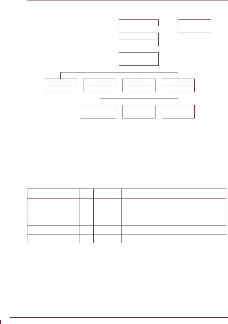
Appendix I: SNMP MIB Definitions
APCD-LM043-8.0 (DRAFT C) 267
WaveRider EUM Enterprise MIBs
The structure of the EUM MIBs is illustrated in Figure 65.
Figure 65 EUM MIBs
Each of the MIBs in Figure 65 is discussed in the following sections.
EUM Base MIB
All values in Table 73, which are read only, are prefixed with 1. 3. 6.1.4.1. 2979.12.
Table 73 WaveRider EUM Base MIB
EUM General Information Group
All values in Table 74 are prefixed with 1.3.6.1.4.1.2979.12.1.
MIB Name OID Value Type Description
eumGlobal 1 MIB EUM general data.
eumRadioConfig 2 MIB EUM configuration and setup data.
eumRadioStats 3 MIB EUM radio statistics.
eumEtherStats 4 MIB EUM Ethernet statistics
eumUSBStats 5 MIB EUM USB statistics.
WaveRider (2979)
waverider
eumGlobal
eum3000pmacglob
eumRadioConfig
eum3000pmacradcfg
eumRadioStats
eum3000pmacrs
eumEtherStats
eum3000pmaces
eumRadioStatsGeneral
eum3000pmacrsgen
eumRadioStatsDriver
eum3000pmacrsdrv
eumRadioStatsAtmel
eum3000pmacrsatmel
Enterprise (1.3.6.1.4.1)
LMS3000 EUM
eum3000pmac
MIB Name
MIB File Prefix
Legend

268 APCD-LM043-8.0 (DRAFT C)
Appendix I: SNMP MIB Definitions
Table 74 WaveRider EUM General Information Enterprise MIBs
EUM Radio Configuration Group
All EUM Radio Configuration Group MIB values are read only. All values in Table 75 are
prefixed with 1.3.6.1.4.1.2979.12.2.
Table 75 WaveRider EUM Radio Configuration Enterprise MIBs
MIB Name OID Value Type Status Accepted
Values Description
eumGlobalSerialNumber 1 String R EUM hardware serial
number
eumGlobalSoftwareVersion 2 String R EUM firmware version.
eumGlobalHardwareVersion 3 String R EUM hardware version.
eumGlobalCapability 4 Integer R Special option
identification mask.
eumGlobalStatus 5 Integer R 1: startup
2: dead
3: ok
4: suspect
Current status of the radio
interface. For now, this
field returns ‘ok’.
eumGlobalSaveCounter 6 Counter R A count of the number of
times the configuration is
saved. Initially, this field
always returns ‘0’.
eumGlobalConfigFiles 7 String R A list of configuration files
for the EUM. The list is
delimited with a semicolon;
i.e., “basic.cfg;route.cfg, ...”
eumGlobalReset 8 Integer W 1: reset Not functional at this time.
eumGlobalReload 9 Integer W 1: reload Not functional at this time.
eumGlobalConnectionType 10 Integer R 1: ethernet
2: usb
The type of customer
connection.
MIB Name OID Value
Type Accepted Values Description
eumRadioConfigVersion 1 String Radio firmware version.
eumRadioUnitMacAddress 2Physical
Address
MAC address Radio MAC address.
eumRadioConfigFrequency 3Integer Radio frequency in use (in
1/10ths of a MHz)
eumRadioConfigDomain 4Integer 0: IEEE
1: FCC or IC/Canada
Current regulatory domain
for which the radio is
configured.
eumRadioHardwareRevision 5String Radio hardware revision.

Appendix I: SNMP MIB Definitions
APCD-LM043-8.0 (DRAFT C) 269
EUM Radio Statistics Group
All EUM Radio Statistics Group MIB values are read only. All values in Table 76 are prefixed
with 1.3.6.1.4.1.2979.12.3.
Table 76 WaveRider EUM Radio Statistics MIB
MIB Name OID Value
Type Description
eumRadioStatsGeneral 1 MIB General radio statistics.
eumRadioStatsDriver 2 MIB Radio driver statistics
eumRadioStatsAtmel 3 MIB Radio MAC statistics.

270 APCD-LM043-8.0 (DRAFT C)
Appendix I: SNMP MIB Definitions
EUM Radio General Statistics Group
All EUM Radio General Statistics Group MIB values are read only. All values in Table 77 are
prefixed with 1.3.6.1.4.1.2979.12.3.1.
Table 77 WaveRider EUM Radio General Statistics Group MIB
EUM Radio Driver Statistics Group
All EUM Radio Driver Statistics Group MIB values are read only. All values in Table 78 are
prefixed with 1.3.6.1.4.1.2979.12.3.2.
Table 78 WaveRider EUM Radio Driver Statistics Group MIB
MIB Name OID Value Type Description
eumRadioGenRSSI 1 Integer Radio receive signal strength indicator, in dBm. ‘0’
indicates no signal present.
eumRadioGenTPI 2 Counter The radio transmit power indicator.
MIB Name OID Value Type Description
eumRadioDrvEvents 1 Counter Number of interrupts received (any interrupt) in the
radio driver ISR (Interrupt Service Routine)
eumRadioDrvRxComplete 2 Counter Number of receive complete interrupts received by
the radio driver ISR.
eumRadioDrvTxComplete 3 Counter Number of transmit complete interrupts received by
the radio driver ISR.
eumRadioDrvCmdComplete 4 Counter Number of command complete interrupts received
by the radio driver ISR.
eumRadioDrvFatalEvent 5 Counter Number of fatal error interrupts received by the
radio driver ISR.
eumRadioDrvTxPowerRailEvent 6 Counter Number of Tx Power alarm interrupts received by
the radio driver ISR.
eumRadioDrvUnknownEvent 7 Counter Number of received an unknown/no event interrupts
received by the radio driver ISR.
eumRadioDrvSend 8 Counter Number of packets sent successfully by the radio
driver transmit queue.
eumRadioDrvSendQFull 9 Counter Number of packets not sent because the radio
driver transmit queue was full.
eumRadioDrvSendUnavailable 10 Counter Number of times invalid (null) mblks were sent to
the radio driver for transmission.
eumRadioDrvSendNotEnabled 11 Counter Number of times tried to send packets before the
radio driver was started; i.e., before the device was
up and working.
eumRadioDrvAMMPut 12 Counter Number of times a packet was successfully sent to
the MAC-layer shared memory for transmission
over the air.

Appendix I: SNMP MIB Definitions
APCD-LM043-8.0 (DRAFT C) 271
EUM Radio MAC Statistics Group
All EUM Radio MAC Statistics Group MIB values are read only. All values in Table 79 are
prefixed with 1.3.6.1.4.1.2979.12.3.3.
Table 79 WaveRider EUM Radio MAC Statistics Group MIB
eumRadioDrvAMMQFull 13 Counter Number of times a packet could not be sent to the
MAC-layer shared memory because there were no
transmit descriptors left. Radio driver tries 5 more
times to send the packet.
eumRadioDrvAMMQFullDiscard 14 Counter Number of times, after 5 attempts, a packet could
not be sent to the MAC-layer shared memory
because there were no transmit descriptors left.
Packet is discarded.
eumRadioDrvGet 15 Counter Number of packets received from the MAC-layer
shared memory.
eumRadioDrvQEmpty 16 Counter Number of times there was a receive interrupt, but
nothing available to read out of the MAC-layer
shared memory.
eumRadioDrvRx 17 Counter Number of successfully received packets.
eumRadioDrvRxNotAvailable 18 Counter Number of times the radio driver could not allocate
an mblk (memory block) for storing a packet
retrieved from the MAC-layer shared memory.
eumRadioDrvNotEnabled 19 Counter Number of times the radio driver received a receive
interrupt, but the radio driver was not yet up and
running. The received packet is ignored in this
case.
MIB Name OID Value Type Description
eumRadioMACRxDataPayloads 1 Counter Number of Ethernet frames received
correctly from the air interface.
eumRadioMACRxDataOctets 2 Counter Number of data octets received correctly
from the air interface.
eumRadioMACRxCtrlPayloads 3 Counter Number of control payloads received
correctly from the air interface.
eumRadioMACRxPayloadFailInvalidType 4 Counter Number of times an unknown type of
payload was received from the air interface.
eumRadioMACRxPayloadFailGiant 5 Counter Number of times a payload that was too
long was received from the air interface,
and therefore discarded.
eumRadioMACNullRxDesc 6 Counter Number of times the internal MAC receive
interface was corrupted.
eumRadioMACTxDataPayloads 7 Counter Number of Ethernet frames transmitted to
the air interface.
MIB Name OID Value Type Description

272 APCD-LM043-8.0 (DRAFT C)
Appendix I: SNMP MIB Definitions
eumRadioMACTxDataOctets 8 Counter Number of data octets transmitted to the air
interface.
eumRadioMACTxCtrlPayloads 9 Counter Number of control payloads transmitted to
the air interface.
eumRadioMACTxPayloadFailInvalidType 10 Counter Number of times a payload of an unknown
type was discarded.
eumRadioMACTxPayloadFailGiant 11 Counter Number of times a payload that was too
long was discarded.
ccRadioMACTxPayloadFailInvalidDesc 12 Counter Number of times the internal MAC transmit
interface was corrupted.
eumRadioMACTxBufferFullOnArrival 13 Counter Number of transmit packets that were
queued for delivery.
eumRadioMACCmdTimeOuts 14 Counter Number of times the MAC-layer
management message was incomplete.
eumRadioMACCmdMissedIRQs 15 Counter Number of times there was no response to
the MAC-layer management message.
eumRadioMACFalseCmdIRQs 16 Counter Number of times a hardware IRQ was
detected with no message associated. This
MIB parameter is used primarily by
software development.
eumRadioMACCmdStatusErrors 17 Counter Number of times the MAC-layer
management message was rejected.
eumRadioMACFatalError 18 Counter Number of nonrecoverable MAC-layer
errors, each requiring an EUM reboot.
eumRadioMACTxRailError 19 Counter Transmit power alarm interrupt.
eumRadioMACRxPacketsDirected 20 Counter Number of times a poll for the EUM is
received from the CCU with the correct
HCRC.
eumRadioMACRxPktsBroadcast 21 Counter Number of broadcast packets (see note 1)
received with the correct HCRC.
eumRadioMACRxPktsNoMatch 22 Counter Number of packets correctly received, but
not directed to, this station.
eumRadioMACRxPktsDuplicate 23 Counter Number of duplicate payloads (see note 1)
received and discarded. Indicates that a
MAC layer acknowledgement was lost.
eumRadioMACRxPktsRuntFail 24 Counter Number of packets received that were
shorter than the minimum size.
eumRadioMACRxPktsLongFail 25 Counter Number of packets received that were
longer than the maximum size.
eumRadioMACRxPktsHCRCFail 26 Counter Number of packets received with a MAC
header CRC failure (header corrupted).
eumRadioMACRxPktsICVFail 27 Counter Number of packets received with an
encryption (WEP, wireless equivalent
privacy) key mismatch (see note 3).
MIB Name OID Value Type Description

Appendix I: SNMP MIB Definitions
APCD-LM043-8.0 (DRAFT C) 273
eumRadioMACRxPktsFCSFail 28 Counter Number of packets received with a Frame
Check Sequence failure (payload
corrupted).
eumRadioMACRxPktsAssocFail 29 Counter Total number of times a received packet is
discarded because no association can be
made.
eumRadioMACRxPktsIncomplete 30 Counter Number of times the receive DMA for a
payload does not complete (internal error).
eumRadioMACRxPayloadsFailFull 31 Counter Number of times a received payload has to
be discarded because either no receive
descriptor was available, or there was not
enough buffer space.
eumRadioMACRxPayloadsDelivered 32 Counter Number of payloads that this station
received correctly.
eumRadioMACRxPktsEmpty 33 Counter Number of packets received with no
payload.
eumRadioMACTxPkts 34 Counter Number of packets transmitted.
eumRadioMACTxPktsEmpty 35 Counter Number of packets transmitted with no
payload.
eumRadioMACTxPayloads 36 Counter Number of payloads transmitted.
eumRadioMACTxPayloadsBCast 37 Counter Total number of broadcast payloads
transmitted.
eumRadioMACTxPayloads10k 38 Counter Number of payloads acknowledged after
the first transmission.
eumRadioMACTxPayloads20k 39 Counter Number of payloads acknowledged after
the second transmission.
eumRadioMACTxPayloads30k 40 Counter Number of payloads acknowledged after
the third transmission.
eumRadioMACTxPayloads40k 41 Counter Number of payloads acknowledged after
the fourth transmission.
eumRadioMACTxPayloadsFailRetry 42 Counter Number of payloads that failed to transmit
due to the retry limit.
eumRadioMACTxPayloadFailDeleted 43 Counter Total number of payloads returned to the
host because an association could not be
created.
eumRadioMACTxPayloadsBadParam 44 Counter Number of payloads returned to the host
because they are improperly formed
(internal error).
eumRadioMACTxPayloadsVnetInactive 45 Counter Total number of payloads returned to host
because the virtual net was not active.
emRadioMACTxPayloadAssocFailed 46 Counter Total number of payloads returned to the
host because an association could not be
created.
eumRadioMACTxPayloadsTimeout 47 Counter Number of payloads returned to the host
because of timeout.
MIB Name OID Value Type Description

274 APCD-LM043-8.0 (DRAFT C)
Appendix I: SNMP MIB Definitions
Notes:
•A
packet is the basic unit of transmission. A packet may or may not contain a payload.
A payload is user data, which may be an Ethernet frame or a logical link layer control
message.
• WEP is not supported in this release.
• Registration occurs once per EUM and/or CCU boot time. Deregistration may occur if
an EUM is not authorized (a registration/deregistration request pair occurs periodically
while that EUM is powered ON) or if the EUM does not respond to multiple
consecutive polls, such as when it is powered OFF.
• Association occurs when there is traffic to send to or from an EUM. Disassociation
occurs if there is no traffic to or from an EUM for a short period of time.
EUM Ethernet Statistics Group
All EUM Ethernet Statistics Group MIB values are read only. All values in Table 80 are
prefixed with 1.3.6.1.4.1.2979.12.4.
eumRadioMACTxPayloadQueueTooLong 48 Counter Total number of payloads returned to the
host because the EUM’s transmit queue
was too long.
eumRadioMACTxPayloadEmpty 49 Counter Total number of empty payloads received
and returned to host (GOS directives).
eumRadioMACReplyOrRssiTimeout 50 Counter Number of times the RSSI timer expired
because the EUM had not received
anything from the CCU for more than 0.5s.
eumRadioMACRestarts 51 Counter Number of times that the MAC layer
recovered from an internal error or
unexpected event.
eumRadioMACRegRequests 52 Counter Number of registration requests transmitted
(see note 4).
eumRadioMACRegResponse 53 Counter Number of registration responses received
(see note 4).
eumRadioMACDeregRequests 54 Counter Number of deregistration requests received
(see note 4).
eumRadioMACDeregInits 55 Counter Number of deregistration initialization
messages to the host.
eumRadioMACDisassociationRequests 56 Counter Number of disassociation requests
received (see note 5).
eumRadioMACDisassociationInits 57 Counter Number of disassociation initialization
messages to the host.
MIB Name OID Value Type Description

Appendix I: SNMP MIB Definitions
APCD-LM043-8.0 (DRAFT C) 275
Table 80 WaveRider CCU Ethernet Statistics Group MIB
MIB Name OID Value Type Description
eumEtherInterrupts 1 Counter Total number of interrupts received by the Ethernet
driver ISR, interrupt service routine.
eumEtherRxInterrupt 2 Counter Number of receive complete interrupts received by
the Ethernet driver ISR.
eumEtherRxOverrunInterrupt 3 Counter Number of overrun interrupts received by the
Ethernet driver ISR. An overrun occurs when a
received packet has exceeded the packet size, or
the processor has missed one or more packets.
eumEtherRxInProgressInterrupt 4 Counter Number of times a receive complete interrupt was
received by the Ethernet driver ISR before the
current packet was finished.
eumEtherTxCompleteInterrupt 5 Counter Number of normal transmit interrupts received by
the Ethernet driver ISR.
eumEtherTxErrorInterrupt 6 Counter Number of transmit error interrupts received by the
Ethernet driver ISR.
eumEtherTxCarrierLostInterrupt 7 Counter Number of transmit carrier lost interrupts received
by the Ethernet driver ISR.
eumEtherTxAllocInterrupt 8 Counter Number of transmit allocation complete interrupts
received by the Ethernet driver ISR.
eumEtherTxEPHInterrupt 9 Counter Number of transmit EPH interrupts (Ethernet
protocol handler interrupts) received by the
Ethernet driver ISR.
eumEtherTxERCVInterrupts 10 Counter Number of transmit ERCV interrupts (early receive
interrupts) received by the Ethernet driver ISR..
eumEtherRxData 11 Counter Number of packets received and accepted by the IP
stack.
eumEtherRxDataError 12 Counter Number of packets received and rejected by the IP
stack because of errors.
eumEtherRxDataMblkAllocError 13 Counter Number of packets lost due to insufficient memory
resources.
eumEtherRxDataLenghtError 14 Counter Number of packets received that violate Ethernet
packet length rules.
eumEtherRxDatasDiscards 15 Counter Number of packets discarded because the unit was
not ready to receive data.
eumEtherTxData 16 Counter Number of packets received and placed on the
transmit queue.
eumEtherTxDataQFull 17 Counter Number of packets discarded because the transmit
queue was full.
eumEtherTxOk 18 Counter Number of packets sent correctly.
eumEtherTxTimeout 19 Counter Number of times the packet transmit has timed out.
eumEtherTxSemWait 20 Counter Number of times a transmit semaphore could not be
taken in the timeout period.

276 APCD-LM043-8.0 (DRAFT C)
Appendix I: SNMP MIB Definitions
EUM RFC MIB-II Traps
RFC MIB-II Traps
Table 81 EUM RFC MIB-II Traps
MIB Name OID Description
coldStart 1.3.6.1.2.1.11.0.0 Power Cycle or Power On
authenticationFailure 1.3.6.1.2.1.11.0.4 An SNMP request has failed due to improper authentication

APCD-LM043-8.0 (DRAFT C) 277
Appendix J Operating Statistics
The CCU and EUM provide a comprehensive set of operating statistics for each of the
following:
•Ethernet Statistics on page 278
•Radio Driver Statistics on page 280
•MAC Interface Statistics on page 282
•Routing/Bridging Protocol Statistics on page 287
•RADIUS Client Statistics on page 291
•Network Interface Statistics on page 293
•System Load Statistics (Radio Meter) on page 295
•CCU Watch Statistics on page 298
•Registration Table (CCU only) on page 301
•CCU and EUM System Log Statistics on page 302
These statistics can be used as a diagnostic and troubleshooting tool when system
performance is being impaired by interference, radio link degradation, network problems,
atypical end-user applications, capacity issues, and so on.
All of these statistics are available through the command-line interface. Most of the statistics
are also available in the CCU and EUM MIBs, if you want to monitor the LMS4000 900 MHz
radio network from an SNMP manager.
CAUTION: Each CCU and EUM statistic is a maximum 32-bit
number (maximum 4,294,967,296). If a statistics counter exceeds
its maximum value, the counter resets to zero and begins again.
When this occurs, you must either take the rollover into account,
or reset the statistics to re-synchronize the counters. To reset
statistics, type stats clear at the command prompt and press
Enter.

278 APCD-LM043-8.0 (DRAFT C)
Appendix J: Operating Statistics
To Display (all) Statistics from the CLI
• At the command prompt, type stats and press Enter.
The following sections describe each of the statistics in detail and the procedure for obtaining
specific sets of statistics (Ethernet, Radio, and so on).
Ethernet Statistics
Ethernet Statistics present operational information about data passing through the CCU and
EUM Ethernet ports. These statistics are described in Table 82.
As indicated in Table 82, all of the Ethernet statistics are available in a WaveRider MIB.
Table 82 Ethernet Statistics
Statistic Description
Interrupts Total number of interrupts received by the Ethernet
driver ISR, interrupt service routine.
RX Interrupts Number of receive complete interrupts received by the
Ethernet driver ISR.
RX Overrun Interrupts Number of overrun interrupts received by the Ethernet
driver ISR. An overrun occurs when a received packet
has exceeded the packet size, or the processor has
missed one or more packets.
RX In Progress Interrupts Number of times a receive complete interrupt was
received by the Ethernet driver ISR before the current
packet was finished.
TX Complete Interrupts Number of normal transmit interrupts received by the
Ethernet driver ISR.
TX Error Interrupts Number of transmit error interrupts received by the
Ethernet driver ISR.
TX Carrier Lost Interrupts Number of transmit carrier lost interrupts received by
the Ethernet driver ISR.
TX Alloc Interrupts Number of transmit allocation complete interrupts
received by the Ethernet driver ISR.
TX EPH Interrupts Number of transmit EPH interrupts (Ethernet protocol
handler interrupts) received by the Ethernet driver
ISR.
TX ERCV Interrupts Number of transmit ERCV interrupts (early receive
interrupts) received by the Ethernet driver ISR.

Appendix J: Operating Statistics
APCD-LM043-8.0 (DRAFT C) 279
To view the Ethernet statistics:
60:03:3a> stats ethernet
-------------------- Ethernet Statistics -----------------------
Interrupts : 4066
RX Interrupts : 3988
RX Overrun Interrupts : 0
RX In Progress Interrupts : 0
TX Complete Interrupts : 78
TX Error Interrupts : 0
TX Carrier Lost Interrupts : 0
TX Alloc Interrupts : 0
TX EPH Interrupts : 0
TX ERCV Interrupts : 0
RX Data : 5935
RX Data Error : 0
RX Data Mblk Alloc Error : 0
RX Data Length Error : 0
RX Discards (No Space Available) : 0
TX Data : 78
TX Data Q Full : 0
TX'D OK : 78
TX Timeout : 0
TX Sem Wait : 0
60:03:3a>
RX Data Number of packets received and accepted by the IP
stack.
RX Data Error Number of packets received and rejected by the IP
stack because of errors.
RX Data Mblk Alloc Error Number of packets lost due to insufficient memory
resources.
RX Data Length Error Number of packets received that violate Ethernet
packet length rules.
RX Discards Number of packets discarded because the unit was
not ready to receive data.
TX Data Number of packets received and placed on the
transmit queue.
TX Data Q Full Number of packets discarded because the transmit
queue was full.
TX’D OK Number of packets sent correctly.
TX Timeout Number of times the packet transmit has timed out.
TX Sem Wait Number of times a transmit semaphore could not be
taken in the timeout period.
Statistic Description

280 APCD-LM043-8.0 (DRAFT C)
Appendix J: Operating Statistics
Radio Driver Statistics
Radio Driver Statistics present operational information about data passing through the CCU
and EUM radio driver and ports. These statistics are described in Table 83.
As indicated in Table 83, all of the Radio Driver statistics are available in a WaveRider MIB.
Table 83 Radio Driver Statistics
Statistic Description
Events Number of interrupts received (any interrupt) in the
radio driver ISR (Interrupt Service Routine)
Rx Complete Event Number of receive complete interrupts received by the
radio driver ISR.
Tx Complete Event Number of transmit complete interrupts received by
the radio driver ISR.
Cmd Complete Event Number of command complete interrupts received by
the radio driver ISR.
Fatal Error Event Number of fatal error interrupts received by the radio
driver ISR.
Tx Power Rail Event Number of Tx Power alarm interrupts received by the
radio driver ISR.
Unknown Event Number of received an unknown/no event interrupts
received by the radio driver ISR.
Send Number of packets sent successfully by the radio
driver transmit queue.
Send Q Full Number of packets not sent because the radio driver
transmit queue was full.
Send MBlk Unavailable Number of times invalid (null) mblks (memory blocks)
were sent to the radio driver for transmission.
Send Not Enabled Number of times tried to send packets before the radio
driver was started; i.e., before the device was up and
working.
AMM Put Number of times a packet was successfully sent to the
MAC-layer shared memory for transmission over the
air.
AMM Q Full Number of times a packet was delayed before being
placed in the MAC-layer shared memory due to a full
transmit queue.
AMM Q Full Discard Number of times a packet was discarded due to the
MAC-layer shared memory transmit queue not
draining.

Appendix J: Operating Statistics
APCD-LM043-8.0 (DRAFT C) 281
To view the radio driver statistics:
60:03:3a> stats rad
------------------- Radio Driver Statistics ---------------------
Events : 634
Rx Complete Event : 300
Tx Complete Event : 329
Cmd Complete Event : 3
FATAL ERROR Event : 0
Tx Power Rail Event : 0
Unknown Event : 2
Send : 329
Send Q Full : 0
Send MBlk Unavailable : 0
Send Not Enabled : 1
AMM Put : 329
AMM Q Full : 0
AMM Q Full Discard : 0
AMM get : 300
AMM Q Empty : 1
Receive : 300
Receive MBlk Unavailable : 0
Receive Not Enabled : 0
60:03:3a>
AMM Get Number of packets received from the MAC-layer
shared memory.
AMM Q Empty Number of times there was a receive interrupt, but
nothing available to read out of the MAC-layer shared
memory.
Receive Number of successfully received packets.
Receive MBlk Unavailable Number of times the radio driver could not allocate an
mblk (memory block) for storing a packet retrieved
from the MAC-layer shared memory.
Receive Not Enabled Number of times the radio driver received a receive
interrupt, but the radio driver was not yet up and
running. The received packet is ignored in this case.
Statistic Description

282 APCD-LM043-8.0 (DRAFT C)
Appendix J: Operating Statistics
MAC Interface Statistics
MAC Interface Statistics present operational information about data which is processed by the
CCU and EUM MAC layer. These statistics are described in Table 84.
As noted in Table 84, most of the MAC interface statistics are available in a WaveRider MIB.
Table 84 MAC Interface Statistics
Statistic Description
Rx Data Payloads Number of data payloads received correctly from the
air interface.
Rx Data Octets Number of data octets received correctly from the air
interface.
Rx Ctrl Payloads Number of control payloads received correctly from
the air interface.
Rx Payload Fail Invalid Type Number of times an unknown type of payload was
received from the air interface.
Rx Payload Fail Giant Number of times a payload that was too long was
received from the air interface, and therefore
discarded.
Null Rx Descriptors Number of times the internal MAC receive interface
was corrupted.
Tx Data Payloads Number of data payloads transmitted to the air
interface.
Tx Data Octets Number of data octets transmitted to the air interface.
Tx Ctrl Payloads Number of control payloads transmitted to the air
interface.
Tx Payload Fail Invalid Type Number of times a payload of an unknown type was
discarded.
Tx Payload Fail Giant Number of times a payload that was too long was
discarded.
Tx Payload Fail Invalid Desc Number of times the internal MAC transmit interface
was corrupted.
Atmel Tx Buffer full on arrival Number of transmit packets that were queued for
delivery.
Command Time Outs Number of times the MAC-layer management
message was incomplete.
Command Missed IRQs Number of times there was no response to the MAC-
layer management message.

Appendix J: Operating Statistics
APCD-LM043-8.0 (DRAFT C) 283
False Command IRQs Number of times a command failed because the
previous command was still being processed.
Command Status Errors Number of times the MAC-layer management
message was rejected.
Atmel Fatal Error Not used.
Unused Statistic Not used.
rxPktsDirected At the CCU, the number of times a reply from the EUM
is received with the correct HCRC (header cyclic
redundancy check). In the EUM, the number of times a
poll for the EUM is received from the CCU with the
correct HCRC.
rxPktsBroadcast At the CCU, the number of times an EUM succeeds in
a random access. Note that all EUM packets are
directed to the CCU, not broadcast. At the EUM, the
number of broadcast packets (see note 1) received
with the correct HCRC. These are also random access
opportunities.
rxPktsNoMatch Number of packets correctly received, but not directed
to, this station.
rxPktsDuplicate Number of duplicate payloads (see note 1) received
and discarded. Indicates that a MAC layer
acknowledgement was lost.
rxPktsRuntFail Number of packets received that were shorter than the
minimum size.
rxPktsLongFail Number of packets received that were longer than the
maximum size.
rxPktsHCRCFail Number of packets received with a MAC header CRC
failure (header corrupted).
rxPktsICVFail Number of packets received with an encryption (WEP,
wireless equivalent privacy) key mismatch (see note
3).
rxPktsFCSFail Number of packets received with a Frame Check
Sequence failure (payload corrupted).
rxPktsAssocFail Number of times a received packet had to be
discarded because too many EUMs were already
associated. [CCU only]
rxPktsIncomplete Number of times the receive DMA for a payload does
not complete (internal error).
rxPayloadsFailFull Number of times a received payload has to be
discarded because either no receive descriptor was
available, or there was not enough buffer space.
Statistic Description

284 APCD-LM043-8.0 (DRAFT C)
Appendix J: Operating Statistics
rxPayloadsDelivered Number of payloads that this station received
correctly.
rxPktsEmpty Number of packets received that are directed to this
station, but that did not contain a payload.
txPkts Number of packets transmitted.
txPktsEmpty Number of packets transmitted with no payload.
txPayloads Number of payloads transmitted.
txPayloadsBCast Number of broadcast payloads transmitted. [CCU
only]
txPayloads10k Number of payloads acknowledged after the first
transmission.
txPayloads20k Number of payloads acknowledged after the second
transmission.
txPayloads30k Number of payloads acknowledged after the third
transmission.
txPayloads40k Number of payloads acknowledged after the fourth
transmission.
txPayloadsFailRetry Number of payloads that failed to transmit due to the
retry limit.
txPayloadsFailAssocDeleted Number of payloads that were discarded because the
EUM was unreachable or deauthorized. [CCU only]
txPayloadsFailBadParam Number of payloads returned to the host because they
are improperly formed (internal error).
txPayloadsFailVnetInactive Number of payloads returned to the host because the
virtual net was not active (internal error). [CCU only]
txPayloadsFailAssocFail Number of payloads returned to the host because too
many other EUMs were already associated. [CCU
only]
txPayloadsFailTimeout Number of payloads returned to the host because of
timeout.
txPayloadsFailQueueTooLong Number of payloads returned to the host because the
transmit queue for the EUM was too long (see note 4).
[CCU only]
txPayloadsEmpty Not used.
replyOrRssiTimeouts At the CCU, the number of times that no response was
received to a directed poll. At the EUM, the number of
times the RSSI timer expired because the EUM had
not received anything from the CCU for more than
0.5s.
Statistic Description

Appendix J: Operating Statistics
APCD-LM043-8.0 (DRAFT C) 285
Notes:
•A
packet is the basic unit of transmission. A packet may or may not contain a payload.
A payload is user data, which may be an Ethernet frame or a logical link layer control
message.
• WEP is not supported in this release.
• The CCU maintains a transmit queue for each EUM. The length of this queue is
limited, to keep one EUM from consuming all the resources and impacting other
EUMs. Discards indicate excessive load by one EUM, possibly due to large TCP
windows.
• Registration occurs once per EUM and/or CCU boot time. Deregistration may occur if
an EUM is not authorized (a registration/deregistration request pair occurs periodically
restarts Number of times that a PAI (physical attachment
interface) state machine restart occurred (internal
error).
registrationRequests At the CCU, the number of registration requests
received (see note 5). At the EUM, the number of
registration requests transmitted (see note 5).
registrationResponses At the CCU, the number of registration responses
transmitted (see note 5). At the EUM, the number of
registration responses received (see note 5).
deregistrationRequests At the CCU, the number of deregistration requests
transmitted (see note 5). At the EUM, the number of
deregistration requests received (see note 5).
deregistrationInits Number of times no response was received from an
EUM, after multiple polls (see note 5). [CCU only]
disassociationRequests At the CCU, the number of disassociation requests
transmitted (see note 6). At the EUM, the number of
disassociation requests received (see note 6).
disassociationInits Number of times the CCU has determined than an
EUM should be disassociated (see note 6). [CCU only]
newAssociations At the CCU, the number of times a new association is
created (see note 6). At the EUM, the number of
transitions to associated state (see note 6).
currentAssociations Number of EUMs currently associated + 1 (see note
6). The one additional association is for “broadcast”.
[CCU only]
unexpectedEvents Number of internal unexpected events.
txDescAvail Indicates the instantaneous number of transmit buffers
that are not in use.
lastQueueTooLongEUM Indicates for which EUM the last packet was
discarded.
Statistic Description

286 APCD-LM043-8.0 (DRAFT C)
Appendix J: Operating Statistics
while that EUM is powered ON) or if the EUM does not respond to multiple
consecutive polls, such as when it is powered OFF.
• Association occurs when there is traffic to send to or from an EUM. Disassociation
occurs if there is no traffic to or from an EUM for a short period of time.
To view the MAC Interface Statistics:
60:03:3a> stats mac
----------------- MAC Interface Statistics --------------------
Rx Data Payloads : 225
Rx Data Octets : 29169
Rx Ctrl Payloads : 68
Rx Payload Fail Invalid Type : 0
Rx Payload Fail Giant : 0
Null Rx Descriptors : 0
Tx Data Payloads : 252
Tx Data Octets : 30919
Tx Ctrl Payloads : 70
Tx Payload Fail Invalid Type : 0
Tx Payload Fail Giant : 0
Tx Payload Fail Invalid Desc : 0
Atmel Tx Buffer full on arrival : 0
Command time outs : 0
Command missed IRQs : 0
False Command IRQs : 2
Command Status Errors : 0
Atmel Fatal Errors : 0
Unused statistic : 0
rxPktsDirected: 86419
rxPktsBroadcast: 73
rxPktsNoMatch: 0
rxPktsDuplicate: 0
rxPktsRuntFail: 0
rxPktsLongFail: 0
rxPktsHCRCFail: 111
rxPktsICVFail: 0
rxPktsFCSFail: 0
rxPktsAssocFail: 0
rxPktsIncomplete: 0
rxPayloadsFailFull: 0
rxPayloadsDelivered: 293
rxPktsEmpty: 86263
txPkts: 96286237
txPktsEmpty: 96285907
txPayloads: 330
txPayloadsBCast: 167
txPayloads1Ok: 151
txPayloads2Ok: 2
txPayloads3Ok: 0
txPayloads4Ok: 1
txPayloadsFailRetry: 1
txPayloadsFailAssocDeleted: 0
txPayloadsFailBadParam: 0
txPayloadsFailVnetInactive: 0
txPayloadsFailAssocFail: 0
txPayloadsFailTimeout: 0
txPayloadsFailQueueTooLong: 0
txPayloadsEmpty: 0
replyOrRssiTimeouts: 968
restarts: 1
registrationRequests: 4
registrationResponses: 4

Appendix J: Operating Statistics
APCD-LM043-8.0 (DRAFT C) 287
deregistrationRequests: 2
deregistrationInits: 0
disassociationRequests: 64
disassociationInits: 64
newAssociations: 71
currentAssociations: 1
unexpectedEvents: 0
txDescAvail: 74
lastQueueTooLongEUM: 00:00:00
60:03:3a>
Routing/Bridging Protocol Statistics
Routing/Bridging Protocol Statistics present operational information about data which is
processed by the bridging, switching, and routing layers. These statistics are described in
Table 85.
The Routing/Bridging Protocol Statistics are not available in the WaveRider MIBs.
Table 85 Routing/Bridging Protocol Statistics
Statistic Description
Rx Eth Dst - App Number of received Ethernet frames
transferred from the Ethernet port to the
EUM application. [EUM only]
Rx Eth Dst - Radio Number of received Ethernet frames
bridged from the Ethernet port to the radio
port. [EUM only]
Rx Eth Dst - To Router (CCU Only) Number of Ethernet frames
received on the Ethernet port sent to the
internal router.
Rx Eth Err - Rx Discard Number of Ethernet frames received on the
Ethernet port discarded because the
destination is known to be on the Ethernet
side or the source address is itself or is
invalid.
Rx Eth Err - Mblk Number of Ethernet frames from the
Ethernet port that were discarded because
of a specific type of memory allocation error.
Rx Eth Err - Msg Buffer Number of Ethernet frames from the
Ethernet port that were discarded because
of a specific type of memory allocation error.
Rx Eth Err - Pkt Size Number of Ethernet frames from the
Ethernet port that were discarded because
the frame was too large or too small to
decode.

288 APCD-LM043-8.0 (DRAFT C)
Appendix J: Operating Statistics
Rx Eth Err - Unknown Ether Type Number of Ethernet frames from the
Ethernet port that were discarded because
they were not IP, ARP, RARP, or PPPoE
frames (example, IPX frame).
Rx Eth Err - Bridge Table Full (CCU Only) Number of Ethernet frames
received on the Ethernet port discarded
because the bridge table was full.
Rx Eth Err - Customer Table Error (EUM Only) Number of Ethernet frames
from the Ethernet port that were discarded
because the host was not allowed air
access or because the bridge table was full.
Rx Eth Err - Invalid NetPool Number of Ethernet frames from the
Ethernet port that were discarded because
of a specific type of memory allocation error.
Rx Eth Err - Could not Duplicate Number of Ethernet frames received on the
Ethernet port discarded because of a
specific type of memory allocation error.
Rx Eth Err - IP Filter Number of Ethernet frames received on the
Ethernet port discarded because they
matched an installed port filter.
Rx Radio Dst - App Number of Ethernet frames received from
the radio and sent to the host application.
Rx Radio Dst - Radio (CCU Only) Number of Ethernet frames
received from the radio and transmitted
back out through the radio (i.e., “switched”).
Rx Radio Dst - To Router (CCU Only) Number of Ethernet frames
received from the radio and sent to the
internal router.
Rx Radio Dst - Eth Number of Ethernet frames received from
the radio and bridged to the Ethernet port.
Rx Radio Err - Reflection Number of Ethernet frames received from
the radio and discarded because the source
address was itself, known to be on the
Ethernet port, or invalid.
Rx Radio Err - Mblk Number of Ethernet frames from the radio
port that were discarded because of a
specific type of memory allocation error.
Rx Radio Err - Msg Buffer Number of Ethernet frames from the radio
port that were discarded because of a
specific type of memory allocation error.
Statistic Description

Appendix J: Operating Statistics
APCD-LM043-8.0 (DRAFT C) 289
Rx Radio Err - Pkt Size Number of Ethernet frames from the radio
port that were discarded because the frame
was too large or too small to decode.
Rx Radio Err - Unknown Ether Type Number of Ethernet frames from the radio
port that were discarded because they were
not IP, ARP, RARP, or PPPoE frames
(example, IPX frame).
Rx Radio Err - Unknown Msg Type Number of Ethernet frames received from
the radio port and discarded because of an
internal routing error.
Rx Radio Err - Invalid NetPool Number of Ethernet frames received from
the radio and discarded because of a
specific type of memory allocation error.
Rx Radio Err - Could not Duplicate Number of Ethernet frames received from
the radio discarded because of a specific
type of memory allocation error.
Rx Radio Err - IP Filter Number of Ethernet frames received from
the radio and discarded because they
matched an installed port filter.
Rx Radio Err - Unreg Request (CCU Only) Number of Ethernet frames
received from the radio port and discarded
because they came from an unregistered
EUM.
Rx Radio Err - Address Table Full (CCU Only) Number of Ethernet frames
received from the radio and discarded
because the address table was full.
Rx Radio Err - Duplicate IP address (CCU Only) Number of ARP packets
received from the radio and discarded
because the source IP address was the
same as the CCU radio IP address.
Last Duplicate IP from EUMID: ID of the EUM from which the last duplicate
IP address was received.
Tx Dst - Eth Number of Ethernet frames that were
transmitted through the Ethernet port.
Tx Dst - Radio Number of Ethernet frames that were
transmitted through the radio port.
Tx Dst - Unknown (CCU Only) Number of transmit Ethernet
frames discarded because the destination
address was not in the bridging or address
tables.
Statistic Description

290 APCD-LM043-8.0 (DRAFT C)
Appendix J: Operating Statistics
To view the Routing Protocol Statistics:
60:03:3a> stats rp
----------------Routing Protocol Statistics -------------------
Rx Eth Dst - App : 337
Rx Eth Dst - Radio : 338
Rx Eth Dst - To Router : 0
Rx Eth Err - Rx Discard (Discard) : 0
Rx Eth Err - Mblk (Discard) : 0
Rx Eth Err - Msg Buffer (Discard) : 0
Rx Eth Err - Pkt Size (Discard) : 0
Rx Eth Err - Unknown Ether Type (Discard) : 0
Rx Eth Err - Bridge Table Full (Discard) : 0
Rx Eth Err - Invalid NetPool (Discard) : 0
Rx Eth Err - Could not Duplicate (Discard) : 0
Rx Eth Err - IP Filter (Discard) : 0
Rx Radio Dst - App : 2667
Rx Radio Dst - Radio : 0
Rx Radio Dst - To Router : 0
Rx Radio Dst - Eth : 1931
Rx Radio Err - Reflection (Discard) : 0
Rx Radio Err - Mblk (Discard) : 0
Rx Radio Err - Msg Buffer (Discard) : 0
Rx Radio Err - Pkt Size (Discard) : 0
Rx Radio Err - Unknown Ether Type (Discard) : 0
Rx Radio Err - Unknown Msg Type (Discard) : 0
Rx Radio Err - Invalid NetPool (Discard) : 0
Rx Radio Err - Could not Duplicate (Discard) : 0
Rx Radio Err - IP Filter (Discard) : 0
Rx Radio Err - Unreg Request (Discard) : 0
Rx Radio Err - Address Table Full (Discard) : 0
Rx Radio Err - Duplicate IP address(Discard) : 0
p Last Duplicate IP from EUMID 00:00:00
Tx Dst - Eth : 1938
Tx Dst - Radio : 1097
Tx Dst - Unregistered (CCU Only) Number of transmit Ethernet
frames discarded because the destination
EUM was unregistered.
Tx Err - Mblk Number of transmit Ethernet frames that
had to be discarded because of a specific
type of memory allocation error.
Tx Err - Msg Buffer Number of transmit Ethernet frames that
had to be discarded because of a specific
type of memory allocation error.
Tx Err - Pkt Size Number of transmit Ethernet frames that
had to be discarded because the frame was
too large or too small to decode.
Tx Err - Could not Duplicate Number of transmit Ethernet frames that
had to be discarded because of a specific
type of memory allocation error.
Statistic Description

Appendix J: Operating Statistics
APCD-LM043-8.0 (DRAFT C) 291
Tx Err - Unknown (Discard) : 0
Tx Err - Unregistered (Discard) : 0
Tx Err - Mblk (Discard) : 0
Tx Err - Msg Buffer (Discard) : 0
Tx Err - Pkt Size (Discard) : 0
Tx Err - Could not Duplicate (Discard) : 0
60:03:3a>
RADIUS Client Statistics
RADIUS Client Statistics, described in Table 86, are generated by the RADIUS client resident
on the CCU.
RADIUS Client Statistics are not available in the WaveRider MIBs.
Table 86 RADIUS Client Statistics
Statistic Description
Tx Access Requests Number of distinct access request messages transmitted (not
including retries).
Tx Accounting Starts Number of distinct accounting start messages transmitted (not
including retries).
Tx Accounting
Updates Number of distinct accounting update messages transmitted (not
including retries).
Tx Accounting Stops Number of distinct accounting stop messages transmitted (not
including retries).
Tx Messages
(including retries) Number of RADIUS packets transmitted, including retries.
Rx Errors Number of received RADIUS messages discarded because they
were too large.
Rx Runts Number of received RADIUS messages discarded because they
were too small.
Rx Invalid Server
Address Number of received RADIUS messages discarded because they
were not from the expected RADIUS server.
Rx Unmatched Id Number of received RADIUS messages discarded because they
did not have the expected message ID.
Rx Unmatched
Length Number of received RADIUS messages discarded because the
internal structure did not match the packet length.
Rx Authenticator Fail Number of received RADIUS messages discarded because the
authenticator was incorrect (e.g., wrong shared secret)

292 APCD-LM043-8.0 (DRAFT C)
Appendix J: Operating Statistics
To view RADIUS Client statistics:
60:06:4e> stats auth
RADIUS Client
Tx Access Requests 71
Tx Accounting Starts 2
Tx Accounting Updates 67
Tx Accounting Stops 0
Tx Messages (including retries) 140
Rx Errors (discard) 0
Rx Runts (discard) 0
Rx Invalid Server Address (discard) 0
Rx Unmatched Id (discard) 0
Rx Unmatched Length (discard) 0
Rx Authenticator Fail (discard) 0
Rx Timeouts 0
Rx Okay 140
Rx Wrong Code (discard) 0
Rx Accept, No GOS (discard) 0
Rx Accept, Misformed GOS (discard) 0
Rx Timeouts Number of times an expected response did not arrive within 3
seconds.
Rx Okay Number of RADIUS messages received with the correct
authenticator.
Rx Wrong Code Number of received RADIUS messages of an unsupported type.
Rx Accept, No GOS Number of received RADIUS access accept responses not
containing a WaveRider vendor-specific attribute.
Rx Accept,
Misformed GOS Number of received RADIUS access accept responses with a
poorly formed WaveRider vendor-specific attribute.
Rx Accept, Unknown
GOS Number of received RADIUS access accept responses specifying
an unknown grade of service.
Rx Access Reject
Okay Number of received RADIUS access reject responses (these
cause an EUM to be denied).
Rx Access Accept
Okay Number of received RADIUS access accept messages with valid
grade of service (these cause an EUM to be assigned that grade of
service).
Rx Accounting
Response Okay Number of received RADIUS accounting responses.
No Access
Response (4
attempts)
No response is received to a RADIUS access request message
after trying the primary and secondary servers twice each.
No Accounting
Response (4
attempts)
No response is received to a RADIUS accounting request
message after trying the primary and secondary servers twice
each.
Statistic Description

Appendix J: Operating Statistics
APCD-LM043-8.0 (DRAFT C) 293
Rx Accept, Unknown GOS (discard) 0
Rx Access Reject Okay 0
Rx Access Accept Okay 71
Rx Accounting Response Okay 69
No Access Response (4 attempts) 0
No Accounting Response (4 attempts) 0
Network Interface Statistics
Network Interface Statistics, described in Table 85, are generated by the IP-protocol suite
resident on the CCU and EUM.
Network Interface Statistics are not available in the WaveRider MIBs.
Table 87 Network Interface Statistics
To view all network interface statistics:
60:03:3a> stats net
----------------- Network Interface Statistics ----------------
ICMP:
20 calls to icmp_error
0 error not generated because old message was icmp
Output histogram:
echo reply: 36
destination unreachable: 20
0 message with bad code fields
0 message < minimum length
0 bad checksum
0 message with bad length
Input histogram:
echo reply: 15
destination unreachable: 15
echo: 36
36 message responses generated
total 3883
badsum 0
tooshort 0
toosmall 0
badhlen 0
Statistic Description
ICMP For information on ICMP, and ICMP-related statistics, refer to
RFC729.
IP For information on IP, and IP-related statistics, refer to RFC791.
TCP For information on TCP, and TCP-related statistics, refer to
RFC793.
UDP For information on UDP, and UDP-related statistics, refer to
RFC768.

294 APCD-LM043-8.0 (DRAFT C)
Appendix J: Operating Statistics
badlen 0
infragments 0
fragdropped 0
fragtimeout 0
forward 69
cantforward 1046
redirectsent 0
unknownprotocol 15
nobuffers 0
reassembled 0
outfragments 0
noroute 0
Active Internet connections (including servers)
PCB Proto Recv-Q Send-Q Local Address Foreign Address (state)
-------- ----- ------ ------ ------------------ ------------------ -------
5cc6b4 TCP 0 0 0.0.0.0.23 0.0.0.0.0 LISTEN
5cc4ac TCP 0 0 0.0.0.0.21 0.0.0.0.0 LISTEN
5cc8bc UDP 0 0 0.0.0.0.123 0.0.0.0.0
5cc9c0 UDP 0 0 0.0.0.0.20001 0.0.0.0.0
5cbb88 UDP 0 0 0.0.0.0.161 0.0.0.0.0
TCP:
0 packet sent
0 data packet (0 byte)
0 data packet (0 byte) retransmitted
0 ack-only packet (0 delayed)
0 URG only packet
0 window probe packet
0 window update packet
0 control packet
0 packet received
0 ack (for 0 byte)
0 duplicate ack
0 ack for unsent data
0 packet (0 byte) received in-sequence
0 completely duplicate packet (0 byte)
0 packet with some dup. data (0 byte duped)
0 out-of-order packet (0 byte)
0 packet (0 byte) of data after window
0 window probe
0 window update packet
0 packet received after close
0 discarded for bad checksum
0 discarded for bad header offset field
0 discarded because packet too short
0 connection request
0 connection accept
0 connection established (including accepts)
0 connection closed (including 0 drop)
0 embryonic connection dropped
0 segment updated rtt (of 0 attempt)
0 retransmit timeout
0 connection dropped by rexmit timeout
0 persist timeout
0 keepalive timeout
0 keepalive probe sent
0 connection dropped by keepalive
0 pcb cache lookup failed
UDP:
2786 total packets
2702 input packets
84 output packets

Appendix J: Operating Statistics
APCD-LM043-8.0 (DRAFT C) 295
0 incomplete header
0 bad data length field
0 bad checksum
2651 broadcasts received with no ports
0 full socket
51 pcb cache lookups failed
20 pcb hash lookups failed
60:03:3a>
System Load Statistics (Radio Meter)
These statistics are only available at the CCU. The load statistics are summarized in Table 88.
System Load Statistics are not available through the WaveRider MIBs.
• The radio meter command—without an argument—prints current totals.
• The radio meter command—with an argument—prints averages at the given
interval.
Table 88 Load Statistics (Radio Meter)
Statistic Description
Time Value of the CCU’s internal 32-bit microsecond timer at the instant the
messages were taken. Time rolls over to “0” about every hour and
eleven minutes.
Fw Pyls Number of payloads transmitted from the CCU to EUMs in this class/
level, including retries.
Fw Bytes Number of bytes of payload transmitted from the CCU to EUMs in this
class/level, including retries.
Rev Pyls Number of payloads transmitted from EUMs in this class/level that are
correctly received by the CCU.
Rev Bytes Number of bytes of payload transmitted from EUMs in this class/level
that are correctly received by the CCU.
Max Vio MaxIPS Violations - Number of times the CCU has not polled an EUM in
this class/level within the inter-poll space defined by the EUM’s grade of
service.
Ideal Vio IdealIPS Violations - Number of times the average inter-poll space for
EUMs in this class/level has been more than 25% higher than the ideal
inter-poll space defined by the grade of service.
#EUMs Number of EUMs in the class/level at the instant in time the load
statistics were collected. The broadcast channel counts as one.

296 APCD-LM043-8.0 (DRAFT C)
Appendix J: Operating Statistics
Notes:
• All counters are continuous; that is, they are never zeroed, except if the unit is reset or
power cycled.
• Payload and poll counters can roll over after a minimum of 50 days.
• Byte counters can roll over after a minimum of 4 hours.
• Violation counters could roll over after 70 seconds if the corresponding parameter was
set too small. A steeply climbing violation counter indicates serious problems with
either the settings or the system load.
To view the load statistics:
60:03:3a> radio meter
CCU Load Meter Time (us): 1201172156
Fw Pyls Fw Bytes Rev Pyls Rev Bytes Max Vio Ideal Vio
Gold Active 0 0 0 0 0 0
Gold Inactive 0 0 0 0 0 0
Silver Active 0 0 0 0 0 0
Silver Inactive 0 0 0 0 0 0
Bronze Active 0 0 0 0 0 0
Bronze Inactive 0 0 0 0 0 0
BE Active 99 8904 117 13047 0 0
BE Inactive 67 2144 57 5154 0 0
Broadcast 173 24127 61 12342 0 0
Overall 339 35175 235 30543 0 0
#EUMs Avg IPS Total Polls Empty Polls
Gold Active 0 0 0 0
Gold Inactive 0 0 0 0
Silver Active 0 0 0 0
Silver Inactive 0 0 0 0
Bronze Active 0 0 0 0
Bronze Inactive 0 0 0 0
BE Active 0 1108 87426 87213
BE Inactive 0 49492 2389 2265
Broadcast 1 1071 97274096 97273862
Overall 1 1071 97363911 97363340
60:03:3a>
Each row on the above table, except for Overall, corresponds to a grade of service/activity
level combination. The last row is the overall totals, which in all cases except IPS, are the sum
of the entries in the column. Active refers to EUMs that have had traffic within the last
activePollTimeout, and Inactive refers to EUMs that have not had traffic within the last
Avg IPS Current low-pass average inter-poll space, in microseconds, for the
class/level at that instant in time, which corresponds to the current
polling rate for EUMs in that class. If no EUMs are currently in the class,
it is the average taken at the time the last EUM exited the class.
Total Polls Number of times the CCU has polled an EUM in the class/level.
Empty Polls Number of times the CCU has polled an EUM in the class/level and did
not either transmit or receive a payload.
Statistic Description

Appendix J: Operating Statistics
APCD-LM043-8.0 (DRAFT C) 297
activePollTimeout and have not timed out on disassociationTime. Therefore payload counts
for inactive EUMs indicate transitions from inactive to active.
NOTE: Broadcast traffic is carried with random access polls. Therefore,
forward traffic (CCU-to-EUM) in the broadcast row is broadcast
traffic, while reverse traffic is random access traffic. The reverse
packet rate should be less than 15% of the total poll rate for the
broadcast traffic, since random access attempts can collide.
Assuming uncorrelated arrivals, this should ensure that 99.7% of
random access attempts succeed (in four retries or less).

298 APCD-LM043-8.0 (DRAFT C)
Appendix J: Operating Statistics
CCU Watch Statistics
The CCU includes the <watch> command, which enables you to monitor link statistics for a
single specified EUM.
•watch xx:xx:xx clears the watch statistics memory and starts watching the
specified EUM.
•watch displays the results of the watch statistics gathering.
While an EUM is being watched, the statistics are incremented only for packets transmitted to
or from the specified EUM.
As part of installing or troubleshooting an EUM, you should “watch” the EUM from the CCU. If
the TxPayloadsFailQueueTooLong statistic increments, then the TCP receive window in the
user’s PC is probably set too high, causing packet discards at the CCU, retransmission on the
network link, and reduced throughput.
NOTE: Long queues at the CCU can also occur due to multiple
concurrent transfers in the process.
You can monitor the MAC statistic “txPayloadsFailQueueTooLong” at the CCU to give an
indication of packet discards due to queue overrun. The MAC statistic
“lastQueueTooLongEUM” at the CCU indicates for which EUM the last packet was discarded.
That EUM can then be “watched” to determine how often discards occur and whether it is a
problem. Some discards may occur simply due to multiple concurrent downloads combined
with heavy system loading. If more than one EUM is having problems, the
“lastQueueTooLongEUM” statistic changes as discards occur.
60:03:3a> watch 60:00:83
Watching 60:00:83
60:03:3a> watch
The EUMID under watch is: 60:30:01
Grade of service: be
RSSI [dBm]: -50
SQ: 6
RNA [dB]: 63
Time since last payload: 0
Input Octets: 1386814542
Input Packets: 20956103
Output Octets: 3395296420
Output Packets: 39582379
Transmitted Packets
No payload : 14192 99.7%
Total : 14229
Transmitted Payloads
1Ok : 34 97.1%
2Ok : 1 2.8%
3Ok : 0 0.0%
4Ok : 0 0.0%
Fail Retry : 0 0.0%
Fail Q Too Long : 0
Fail Timeout : 0
Received and Expected Responses
HCRC Error : 1 0.0%
Directed : 14227 99.9%
Random Access : 0 0.0%

Appendix J: Operating Statistics
APCD-LM043-8.0 (DRAFT C) 299
No Reply Received : 0 0.0%
No Payload : 14194 99.7%
Received Payloads
FCS Error : 0 0.0%
Duplicate : 0 0.0%
Delivered : 33 100.0%
60:03:3a>
NOTE: Input Octets, Input Packets, Output Octets, and
Output Packets are measured from the point of EUM
registration. All statistics below Output Packets are measured
from the point at which the watch xx:xx:xx command was
entered.
Table 89 CCU Watch Statistics
Statistic Description
The EUMID under watch is EUM ID of the EUM being watched.
Grade of service Grade of service (GOS) assigned to the EUM under
watch.
RSSI [dBm] Received radio signal strength from the EUM,
measured in dBm.
NOTE: This is the received level measured at the
CCU.
SQ Service Quality, measured at the same time as the
RSSI measurement was made.
RNA (dB) Difference, in dB, between the RSSI and the noise
floor.
Time since last payload Number of seconds passed since the CCU received
the last payload from the EUM.
Input Octets Number of octets received since registration.
Input Packets Number of packets received since registration.
Output Octets Number of octets transmitted since registration.
Output Packets Number of packets transmitted since registration.
Transmitted Packets
No payload Number of packets received that did not contain a
payload.
Total Number of packets transmitted.
Transmitted Payloads
10k Number of payloads acknowledged after the first
transmission.

300 APCD-LM043-8.0 (DRAFT C)
Appendix J: Operating Statistics
Notes:
•A
packet is the basic unit of transmission. A packet may or may not contain a payload.
A payload is user data, which may be an Ethernet frame or a logical link layer control
message.
20k Number of payloads acknowledged after the second
transmission.
30k Number of payloads acknowledged after the third
transmission.
40k Number of payloads acknowledged after the fourth
transmission.
Fail Retry Number of payloads that failed to transmit due to the
retry limit.
Fail Q Too Long Number of payloads returned to the host because the
transmit queue for the EUM was too long.
Fail Timeout Number of payloads returned to the host because of
timeout.
Received and Expected Responses
HCRC Error Number of packets received with corrupted headers,
in response to polling the EUM.
Directed Number of packets received with correct headers, in
response to polling the EUM.
Random Access Number of packets received with correct headers, in
response to a random access polling. These are
considered successful random accesses.
No Reply Received Number of times the EUM did not respond to a
directed poll.
No Payload Number of packets received that are directed to this
station, from the EUM, but that did not contain a
payload.
Received Payloads
FCS Error Number of packets received with a Frame Check
Sequence failure (payload corrupted).
Duplicate Number of duplicate payloads (see note 1) received
and discarded. Indicates that a MAC layer
acknowledgement was lost.
Delivered Number of payloads received correctly.
txPayloads Number of payloads transmitted.
Statistic Description

Appendix J: Operating Statistics
APCD-LM043-8.0 (DRAFT C) 301
Registration Table (CCU only)
The Registration Table contains a list of all registered EUMs. The CCU automatically builds
and adds to this table as EUMs communicate with the CCU. Every EUM that registers with the
CCU appears in this table. The EUM will be removed from the Registration Table if the:
• EUM has not communicated with the CCU for more than 12 hours because:
• the EUM has been turned off for more than 12 hr., or
• the EUM has had no traffic to send for more than 12 hr., or
• the EUM has lost its RF connection to the CCU for more than 12 hr.
• EUM does not respond to traffic from the CCU. In this case, the EUM will be removed
immediately from the Registration Table.
The Registration Table contains the following entries:
Table 90 Registration Table Entries
NOTE: The Rx-Octets, Rx-Packets, Tx-Octets, and Tx-Packets statistics
are identical to the RADIUS accounting statistics and may be
considered the appropriate usage statistics for billing purposes.
The end of the air table also prints the total number of EUMs registered.
To view the Registration Table:
60:03:3a> air
Table Entry Description
EUM ID EUM ID
GOS Class Grade of Service Class
RSSI (dBm) Radio received signal strength (RSSI) in dBm of the EUM.
Time(s) Time since the last payload was received from the EUM.
Rx-Octets Number of octets received from this EUM in data payloads,
including Ethernet header but not radio MAC header.
Rx-Packets Number of Ethernet packets received from this EUM in
data payloads.
Tx-Octets Number of octets sent to this EUM in data payloads,
including Ethernet header but not radio MAC header.
Tx-Packets Number of Ethernet packets sent to this EUM in data
payloads.
Maximum Associations The maximum number of EUMs that can be associated at
any one instant in time.
Deregistration Count An EUM will be de-registered if it does not respond after
the CCU has sent it this many consecutive polls.

302 APCD-LM043-8.0 (DRAFT C)
Appendix J: Operating Statistics
Maximum Associations: 75
Deregistration Count: 8
REGISTERED EUMs
EUM ID GOS Class RSSI[dBm] Time[s] Rx-Octets Rx-Packets Tx-Octets Tx-Packets
-------------------------------------------------------------------------------
60:05:13 gold -50 1 721564 6610 435914 6236
60:08:60 be -55 78 232140 1983 125470 1794
2 EUMs registered of 300 allowed
60:03:3a>
NOTE: The air command has been used to view the Registration
Table, because reg is too close to reb (reboot).
CCU and EUM System Log Statistics
The System Log Statistics are logged using a subset of the SNMP MIB counters in a comma-
delimited decimal format. Each line in the system log file has eight fields:
•Date/Time Stamp, which is automatically added to the system log. (e.g., 18-DEC-
2001 21:24:39,)
•Line Label, which identifies the statistics line number, so the numbers can be
extracted correctly. (e.g., stat2,) If the system log requires more than nine lines of
statistics, lines following “stat9” are numbered in hexadecimal format. (e.g., stata,)
•Counters. Each line contains up to six counters, with leading commas. Each counter
contains between 2 and 11 characters, including the commas. All counters reset when
the device reboots or when you issue the stats clear command.
Sample system log file:
60:03:3a> sys log 1600
08,time set to 22-JUL-2002 21:57:08 from 132.246.168.148
22-JUL-2002 21:57:38,time set to 22-JUL-2002 21:57:38 from 132.246.168.148
22-JUL-2002 21:58:08,time set to 22-JUL-2002 21:58:08 from 132.246.168.148
22-JUL-2002 21:58:38,time set to 22-JUL-2002 21:58:38 from 132.246.168.148
22-JUL-2002 21:59:08,time set to 22-JUL-2002 21:59:08 from 132.246.168.148
22-JUL-2002 21:59:38,time set to 22-JUL-2002 21:59:38 from 132.246.168.148
22-JUL-2002 22:00:09,time set to 22-JUL-2002 22:00:09 from 132.246.168.148
22-JUL-2002 22:00:39,time set to 22-JUL-2002 22:00:39 from 132.246.168.148
22-JUL-2002 22:01:09,time set to 22-JUL-2002 22:01:09 from 132.246.168.148
22-JUL-2002 22:01:39,time set to 22-JUL-2002 22:01:39 from 132.246.168.148
22-JUL-2002 22:02:09,time set to 22-JUL-2002 22:02:09 from 132.246.168.148
22-JUL-2002 22:02:39,time set to 22-JUL-2002 22:02:39 from 132.246.168.148
22-JUL-2002 22:02:45,stats log now
22-JUL-2002 22:02:45,stat1,446034,1192148,750227,443347,32644966,32704692
22-JUL-2002 22:02:45,stat2,11980819,7,0,0,0,0
22-JUL-2002 22:02:45,stat3,14,0,0,0,0,0
22-JUL-2002 22:02:45,stat4,441485,11539357,415920420,415477917,442503,1422
22-JUL-2002 22:02:45,stat5,440414,332,1,0,0,0
22-JUL-2002 22:02:45,stat6,0,0,0,0,0,0
22-JUL-2002 22:02:45,stat7,9823,1,2,2,2,0
22-JUL-2002 22:02:45,stat8,16,16,18
22-JUL-2002 22:02:45,stat9,0,0,0,0,0,0
22-JUL-2002 22:02:46,stata,0,0,0,26683,0,0
22-JUL-2002 22:02:57,sys log 1600

Appendix J: Operating Statistics
APCD-LM043-8.0 (DRAFT C) 303
60:03:3a>
The system log records every command you enter, either through the serial console port or
through a Telnet session, which can be useful when troubleshooting problems.
The system log also saves the following statistics at each recording period. Each line is
preceded by the date/time stamp and the “statN” label, where “N” is the line number.
Table 91 CCU and EUM System Log Statistics — Line 1
Field Name Description
1 SYSUPTIME Time counter in 1/100 of a second. This counter
allows a parser to determine time difference
between successive statistics, as well as noting if
the unit has rebooted recently. Note that the
current SYSUPTIME counter rolls over every
715,827 seconds (8 days, 6 hours, 50 minutes, 27
seconds).
2 Ethernet Interrupts Total interrupts caused by the Ethernet device,
including completed RX, TX and errors.
3 Ethernet RX Data Number of packets received on Ethernet Interface.
For EUMs which operate in promiscuous mode,
the receiver will record all packets seen on the
Ethernet, including local Ethernet traffic.
4 Ethernet TX Data Number of packets transmitted over the Ethernet
Interface. Only packets from the EUM or from the
radio network should be transmitted.
5 RX Data Octets Total number of octets received in good packets
from the radio. This includes all Ethernet, IP and
TCP/UP headers and checksums as well as user
information. Does not include MAC header or LLC
packets.
6 TX Data Octets Total number of octets transmitted by radio
interface. This includes all Ethernet, IP and TCP/
UP headers and checksums as well as user
information. Does not include MAC header
packets, LLC packets, or retries.

304 APCD-LM043-8.0 (DRAFT C)
Appendix J: Operating Statistics
Table 92 CCU and EUM System Log Statistics — Line 2
Table 93 CCU and EUM System Log Statistics — Line 3
Table 94 CCU and EUM System Log Statistics — Line 4
Field Name Description
1rxPktsDirected CCU: Total responses to directed polls (with
HCRC okay)
EUM: Total directed polls received to this station
(with HCRC okay).
2rxPktsBroadcast CCU: Total responses to random access polls
(with HCRC okay)
EUM: Total broadcast packets received to this
station (with HCRC okay).
3rxPktsNoMatch Total packets received not to this station.
4rxPktsDuplicate Total duplicate packets received and discarded.
5rxPktsRuntFail Total packets received shorter than MAC header
size
6rxPktsLongFail Total packets received longer than max receive
length
Field Name Description
1rxPktsHCRCFail Total packets received with HCRC failure.
2rxPktsICVFail Total packets received with ICV failure (WEP key
mismatch).
3rxPktsFCSFail Total packets received with FCS failure.
4rxPktsAssocFail Total times received packet is discarded because
no association can be made.
5rxPktsIncomplete Total times rx DMA for payload does not complete.
6rxPayloadsFailFull Total times received payload is discarded because
no receive descriptor is available or not enough
buffer space is available.
Field Name Description
1rxPayloadsDelivered Total receive descriptors sent to host.
2rxPktsEmpty Total number of directed packets received to this
station with no payload.
3txPkts Total number of packets transmitted.

Appendix J: Operating Statistics
APCD-LM043-8.0 (DRAFT C) 305
Table 95 CCU and EUM System Log Statistics — Line 5
Table 96 CCU and EUM System Log Statistics — Line 6
4txPktsEmpty Total number of packets transmitted with no
payload.
5txPayloads Total number of payloads transmitted .
6txPayloadsBCast Total number of payloads broadcasted. No ACKs
are expected.
Field Name Description
Field Name Description
1txPayloads10k Total number of payloads acknowledged after the
first transmission.
2txPayloads20k Total number of payloads acknowledged after the
second transmission.
3txPayloads30k Total number of payloads acknowledged after the
third transmission.
4txPayloads40k Total number of payloads acknowledged after the
fourth transmission.
5txPayloadsFailRetry Total number of payloads that fail to transmit due
to retry limit.
6txPayloadsFailAssocDeleted Total number of payloads returned to the host
because the association was deleted.
Field Name Description
1txPayloadsFailBadParam Total number of payloads returned to host
because they are malformed.
2txPayloadsFailVnetInactive Total number of payloads returned to host
because the virtual net was not active.
3txPayloadsFailAssocFail Total number of payloads returned to the host
because an association could not be created.
4txPayloadsFailTimeout Total number of payloads returned to the host
because of timeout.
5txPayloadsFailQueueTooLon
gTotal number of payloads returned to the host
because the EUM's tx queue was too long.
6txPayloadsEmpty Total number of empty payloads received and
returned to host (gos directives).

306 APCD-LM043-8.0 (DRAFT C)
Appendix J: Operating Statistics
Table 97 CCU and EUM System Log Statistics — Line 7
Table 98 CCU and EUM System Log Statistics — Line 8
The statistics in Table 99 and Table 100 are recorded for the CCU only.
Table 99 CCU ONLY System Log Statistics — Line 9
Field Name Description
1replyOrRssiTimeouts CCU: number of times the reply timer expires.
EUM: number of times the RSSI timer expires.
2restarts Number of times PAI state machine restart occurs.
3registrationRequests CCU: Number of registration requests received.
EUM: Number of registration requests transmitted.
4registrationResponses CCU: Number of registration responses
transmitted.
EUM: Number of registration responses received.
5deregistrationRequests CCU: Number of deregistration requests
transmitted.
EUM: Number of deregistration requests received.
6deregistrationInits CCU: Number of deregistration initialization
messages to the host.
Field Name Description
1disassociationRequests CCU: Number of disassociation requests
transmitted.
EUM: Number of disassociation requests
received.
2disassociationInits CCU: Number of disassociation initialization
messages to the host.
3newAssociations CCU: Number of times a new association is
created.
EUM: Number of times transition to associated
state.
Field Name Description
1Gold Average IPS Interpacket Spacing (IPS) for Gold Active Users
2Gold MAX Violations Violations of MAX IPS for Gold Active Users
3Gold Ideal Violations Violations of the ideal IPS for Gold Active Users

Appendix J: Operating Statistics
APCD-LM043-8.0 (DRAFT C) 307
Table 100 CCU ONLY System Log Statistics — Line a
4Silver Average IPS Interpacket Spacing (IPS) for Silver Active Users
5Silver MAX Violations Violations of MAX IPS for Silver Active Users
6Silver Ideal Violations Violations of the ideal IPS for Silver Active Users
Field Name Description
Field Name Description
1Bronze Average IPS Interpacket Spacing (IPS) for Bronze Active Users
2Bronze MAX Violations Violations of MAX IPS for Bronze Active Users
3Bronze Ideal Violations Violations of the ideal IPS for Bronze Active Users
4Best Effort Average IPS Interpacket Spacing (IPS) for Best Effort Active
Users
5Best Effort MAX Violations Violations of MAX IPS for Best Effort Active Users
6Best Effort Ideal Violations Violations of the ideal IPS for Best Effort Active
Users

308 APCD-LM043-8.0 (DRAFT C)
Appendix J: Operating Statistics

APCD-LM043-8.0 (DRAFT C) 309
Appendix K Sample IP Plan
This section includes sample IP plans for an LMS4000 system. There is a sample IP plan for
each of the following network configurations:
•Routed Mode on page 309
•Switched Ethernet and Through-Only Modes on page 322
TIP: For a large system, the CCU radio subnets should lie in
different Ethernet domains to reduce broadcast traffic. This is
automatically the case in Routed Mode, but requires careful
planning of upstream networking equipment in Switched
Ethernet mode. Contact WaveRider Technical Support for
details.
Routed Mode
The following tables provide an example of an IP plan for an LMS4000 system equipped with
fifteen 900 MHz CAPs, using Routed mode:
•CAP IP Addressing Plan on page 310
•CCU Ethernet IP Addressing Plan on page 310
•CCU Radio IP Addressing Plan on page 311
•EUM IP Addressing Plan on page 314
•Subscriber IP Addressing Plan on page 318

310 APCD-LM043-8.0 (DRAFT C)
Appendix K: Sample IP Plan
CAP IP Addressing Plan
Table 101 Example – CAP IP Addressing Plan
CCU Ethernet IP Addressing Plan
Table 102 Example – CCU Ethernet IP Addressing Plan
CAP Element IP Address
Gateway Router 192.168.10.1 /24
CAP Switch 192.168.10.5 /24
CAP UPS 192.168.10.6 /24
SNMP Manager 192.168.10.7 /24
Site CCU CCU Ethernet
Address Site CCU CCU Ethernet
Address
CAP01 CCU01 192.168.10.11 CAP09 CCU01 192.168.10.43
CCU02 192.168.10.12 CCU02 192.168.10.44
CCU03 192.168.10.13 CCU03 192.168.10.45
CCU04 192.168.10.14 CCU04 192.168.10.46
CAP02 CCU01 192.168.10.15 CAP10 CCU01 192.168.10.47
CCU02 192.168.10.16 CCU02 192.168.10.48
CCU03 192.168.10.17 CCU03 192.168.10.49
CCU04 192.168.10.18 CCU04 192.168.10.50
CAP03 CCU01 192.168.10.19 CAP11 CCU01 192.168.10.51
CCU02 192.168.10.20 CCU02 192.168.10.52
CCU03 192.168.10.21 CCU03 192.168.10.53
CCU04 192.168.10.22 CCU04 192.168.10.54
CAP04 CCU01 192.168.10.23 CAP12 CCU01 192.168.10.55
CCU02 192.168.10.24 CCU02 192.168.10.56
CCU03 192.168.10.25 CCU03 192.168.10.57
CCU04 192.168.10.26 CCU04 192.168.10.58
CAP05 CCU01 192.168.10.27 CAP13 CCU01 192.168.10.59
CCU02 192.168.10.28 CCU02 192.168.10.60
CCU03 192.168.10.29 CCU03 192.168.10.61
CCU04 192.168.10.30 CCU04 192.168.10.62

Appendix K: Sample IP Plan
APCD-LM043-8.0 (DRAFT C) 311
CCU Radio IP Addressing Plan
Table 103 Example – CCUs, EUMs, and Subscriber Subnet Data
NOTE: EUMs and PCs are on the same subnet.
Table 104 Example – CCU Radio IP Addressing Plan
CAP06 CCU01 192.168.10.31 CAP14 CCU01 192.168.10.63
CCU02 192.168.10.32 CCU02 192.168.10.64
CCU03 192.168.10.33 CCU03 192.168.140.65
CCU04 192.168.10.34 CCU04 192.168.140.66
CAP07 CCU01 192.168.10.35 CAP15 CCU01 192.168.10.67
CCU02 192.168.10.36 CCU02 192.168.10.68
CCU03 192.168.10.37 CCU03 192.168.10.69
CCU04 192.168.10.38 CCU04 192.168.10.70
CAP08 CCU01 192.168.10.39
CCU02 192.168.10.40
CCU03 192.168.10.41
CCU04 192.168.10.42
Subnet 172.16.0.0
Subnet Mask Bits 22
Subnet Mask 255.255.252.0 (ff.ff.fc.00)
Site CCU CCU Ethernet
Address Site CCU CCU Ethernet
Address
Site CCU Subnet CCU Radio
IP Address CCU Radio Subnet
Range Broadcast
CAP01
CCU01 172.16.4.0 172.16.4.1 172.16.4.1 - 172.16.7.254 172.16.7.255
CCU02 172.16.8.0 172.16.8.1 172.16.8.1 - 172.16.11.254 172.16.11.255
CCU03 172.16.12.0 172.16.12.1 172.16.12.1 - 172.16.15.254 172.16.15.255
CCU04 172.16.16.0 172.16.16.1 172.16.16.1 - 172.16.19.254 172.16.19.255

312 APCD-LM043-8.0 (DRAFT C)
Appendix K: Sample IP Plan
CAP02
CCU01 172.16.20.0 172.16.20.1 172.16.20.1 - 172.16.23.254 172.16.23.255
CCU02 172.16.24.0 172.16.24.1 172.16.24.1 - 172.16.27.254 172.16.27.255
CCU03 172.16.28.0 172.16.28.1 172.16.28.1 - 172.16.31.254 172.16.31.255
CCU04 172.16.32.0 172.16.32.1 172.16.32.1 - 172.16.35.254 172.16.35.255
CAP03 CCU01 172.16.36.0 172.16.36.1 172.16.36.1 - 172.16.39.254 172.16.39.255
CCU02 172.16.40.0 172.16.40.1 172.16.40.1 - 172.16.43.254 172.16.43.255
CCU03 172.16.44.0 172.16.44.1 172.16.44.1 - 172.16.47.254 172.16.47.255
CCU04 172.16.48.0 172.16.48.1 172.16.48.1 - 172.16.51.254 172.16.51.255
CAP04 CCU01 172.16.52.0 172.16.52.1 172.16.52.1 - 172.16.55.254 172.16.55.255
CCU02 172.16.56.0 172.16.56.1 172.16.56.1 - 172.16.59.254 172.16.59.255
CCU03 172.16.60.0 172.16.60.1 172.16.60.1 - 172.16.63.254 172.16.63.255
CCU04 172.16.64.0 172.16.64.1 172.16.64.1 - 172.16.67.254 172.16.67.255
CAP05 CCU01 172.16.68.0 172.16.68.1 172.16.68.1 - 172.16.71.254 172.16.71.255
CCU02 172.16.72.0 172.16.72.1 172.16.72.1 - 172.16.75.254 172.16.75.255
CCU03 172.16.76.0 172.16.76.1 172.16.76.1 - 172.16.79.254 172.16.79.255
CCU04 172.16.80.0 172.16.80.1 172.16.80.1 - 172.16.83.254 172.16.83.255
CAP06 CCU01 172.16.84.0 172.16.84.1 172.16.84.1 - 172.16.87.254 172.16.87.255
CCU02 172.16.88.0 172.16.88.1 172.16.88.1 - 172.16.91.254 172.16.91.255
CCU03 172.16.92.0 172.16.92.1 172.16.92.1 - 172.16.95.254 172.16.95.255
CCU04 172.16.96.0 172.16.96.1 172.16.96.1 - 172.16.99.254 172.16.99.255
CAP07 CCU01 172.16.100.0 172.16.100.1 172.16.100.1 - 172.16.103.254 172.16.103.255
CCU02 172.16.104.0 172.16.104.1 172.16.104.1 - 172.16.107.254 172.16.107.255
CCU03 172.16.108.0 172.16.108.1 172.16.108.1 - 172.16.111.254 172.16.111.255
CCU04 172.16.112.0 172.16.112.1 172.16.112.1 - 172.16.115.254 172.16.115.255
CAP08 CCU01 172.16.116.0 172.16.116.1 172.16.116.1 - 172.16.119.254 172.16.119.255
CCU02 172.16.120.0 172.16.120.1 172.16.120.1 - 172.16.123.254 172.16.123.255
CCU03 172.16.124.0 172.16.124.1 172.16.124.1 - 172.16.127.254 172.16.127.255
CCU04 172.16.128.0 172.16.128.1 172.16.128.1 - 172.16.131.254 172.16.131.255
CAP09 CCU01 172.16.132.0 172.16.132.1 172.16.132.1 - 172.16.135.254 172.16.135.255
CCU02 172.16.136.0 172.16.136.1 172.16.136.1 - 172.16.139.254 172.16.139.255
CCU03 172.16.140.0 172.16.140.1 172.16.140.1 - 172.16.143.254 172.16.143.255
CCU04 172.16.144.0 172.16.144.1 172.16.144.1 - 172.16.147.254 172.16.147.255
Site CCU Subnet CCU Radio
IP Address CCU Radio Subnet
Range Broadcast

Appendix K: Sample IP Plan
APCD-LM043-8.0 (DRAFT C) 313
CAP10 CCU01 172.16.148.0 172.16.148.1 172.16.148.1 - 172.16.151.254 172.16.151.255
CCU02 172.16.152.0 172.16.152.1 172.16.152.1 - 172.16.155.254 172.16.155.255
CCU03 172.16.156.0 172.16.156.1 172.16.156.1 - 172.16.159.254 172.16.159.255
CCU04 172.16.160.0 172.16.160.1 172.16.160.1 - 172.16.163.254 172.16.163.255
CAP11 CCU01 172.16.164.0 172.16.164.1 172.16.164.1 - 172.16.167.254 172.16.167.255
CCU02 172.16.168.0 172.16.168.1 172.16.168.1 - 172.16.171.254 172.16.171.255
CCU03 172.16.172.0 172.16.172.1 172.16.172.1 - 172.16.175.254 172.16.175.255
CCU04 172.16.176.0 172.16.76.1 172.16.176.1 - 172.16.179.254 172.16.179.255
CAP12 CCU01 172.16.180.0 172.16.180.1 172.16.180.1 - 172.16.183.254 172.16.183.255
CCU02 172.16.184.0 172.16.184.1 172.16.184.1 - 172.16.187.254 172.16.187.255
CCU03 172.16.188.0 172.16.188.1 172.16.188.1 - 172.16.191.254 172.16.191.255
CCU04 172.16.192.0 172.16.192.1 172.16.192.1 - 172.16.195.254 172.16.195.255
CAP13 CCU01 172.16.196.0 172.16.196.1 172.16.196.1 - 172.16.199.254 172.16.199.255
CCU02 172.16.200.0 172.16.200.1 172.16.200.1 - 172.16.203.254 172.16.203.255
CCU03 172.16.204.0 172.16.204.1 172.16.204.1 - 172.16.207.254 172.16.207.255
CCU04 172.16.208.0 172.16.208.1 172.16.208.1 - 172.16.211.254 172.16.211.255
CAP14 CCU01 172.16.212.0 172.16.212.1 172.16.212.1 - 172.16.215.254 172.16.215.255
CCU02 172.16.216.0 172.16.216.1 172.16.216.1 - 172.16.219.254 172.16.219.255
CCU03 172.16.220.0 172.16.220.1 172.16.220.1 - 172.16.223.254 172.16.223.255
CCU04 172.16.224.0 172.16.224.1 172.16.224.1 - 172.16.227.254 172.16.227.255
CAP15 CCU01 172.16.228.0 172.16.228.1 172.16.228.1 - 172.16.231.254 172.16.231.255
CCU02 172.16.232.0 172.16.232.1 172.16.232.1 - 172.16.235.254 172.16.235.255
CCU03 172.16.236.0 172.16.236.1 172.16.236.1 - 172.16.239.254 172.16.239.255
CCU04 172.16.240.0 172.16.240.1 172.16.240.1 - 172.16.243.254 172.16.243.255
Site CCU Subnet CCU Radio
IP Address CCU Radio Subnet
Range Broadcast

314 APCD-LM043-8.0 (DRAFT C)
Appendix K: Sample IP Plan
EUM IP Addressing Plan
Table 105 Example – EUM IP Addressing Plan
Site CCU Subnet ID EUM IP Address Range
CAP01 CCU01 EUM001-253 172.16.4.2 - 172.16.4.254
EUM254-300 172.16.5.1 - 172.16.5.47
CCU02 EUM001-253 172.16.8.2 - 172.16.8.254
EUM254-300 172.16.9.1 - 172.16.9.47
CCU03 EUM001-253 172.16.12.2 - 172.16.12.254
EUM254-300 172.16.13.1 - 172.16.13.47
CCU04 EUM001-253 172.16.16.2 - 172.16.16.254
EUM254-300 172.16.17.1 - 172.16.17.47
CAP02 CCU01 EUM001-253 172.16.20.2- 172.16.20.254
EUM254-300 172.16.21.1 - 172.16.21.47
CCU02 EUM001-253 172.16.24.2 - 172.16.24.254
EUM254-300 172.16.25.1 - 172.16.25.47
CCU03 EUM001-253 172.16.28.2 - 172.16.28.254
EUM254-300 172.16.29.1 - 172.16.29.47
CCU04 EUM001-253 172.16.32.2 - 172.16.32.254
EUM254-300 172.16.33.1 - 172.16.33.47
CAP03 CCU01 EUM001-253 172.16.36.2 - 172.16.36.254
EUM254-300 172.16.37.1 - 172.16.37.47
CCU02 EUM001-253 172.16.40.2 - 172.16.40.254
EUM254-300 172.16.41.1 - 172.16.41.47
CCU03 EUM001-253 172.16.44.2 - 172.16.44.254
EUM254-300 172.16.45.1 - 172.16.45.47
CCU04 EUM001-253 172.16.48.2 - 172.16.48.254
EUM254-300 172.16.49.1 - 172.16.49.47

Appendix K: Sample IP Plan
APCD-LM043-8.0 (DRAFT C) 315
CAP04 CCU01 EUM001-253 172.16.52.2 - 172.16.52.254
EUM254-300 172.16.53.1 - 172.16.53.47
CCU02 EUM001-253 172.16.56.2 - 172.16.56.254
EUM254-300 172.16.57.1 - 172.16.57.47
CCU03 EUM001-253 172.16.60.2 - 172.16.60.254
EUM254-300 172.16.61.1 - 172.16.61.47
CCU04 EUM001-253 172.16.64.2 - 172.16.64.254
EUM254-300 172.16.65.1 - 172.16.65.47
CAP05 CCU01 EUM001-253 172.16.68.2 - 172.16.68.254
EUM254-300 172.16.69.1 - 172.16.69.47
CCU02 EUM001-253 172.16.72.2 - 172.16.72.254
EUM254-300 172.16.73.1 - 172.16.73.47
CCU03 EUM001-253 172.16.76.2 - 172.16.76.254
EUM254-300 172.16.77.1 - 172.16.77.47
CCU04 EUM001-253 172.16.80.2 - 172.16.80.254
EUM254-300 172.16.81.1 - 172.16.81.47
CAP06 CCU01 EUM001-253 172.16.84.2 - 172.16.84.254
EUM254-300 172.16.85.1 - 172.16.85.47
CCU02 EUM001-253 172.16.88.2 - 172.16.88.254
EUM254-300 172.16.89.1 - 172.16.89.47
CCU03 EUM001-253 172.16.92.2 - 172.16.92.254
EUM254-300 172.16.93.1 - 172.16.93.47
CCU04 EUM001-253 172.16.96.2 - 172.16.96.254
EUM254-300 172.16.97.1 - 172.16.97.47
CAP07 CCU01 EUM001-253 172.16.100.2 - 172.16.100.254
EUM254-300 172.16.101.1 - 172.16.101.47
CCU02 EUM001-253 172.16.104.2 - 172.16.104.254
EUM254-300 172.16.105.1 - 172.16.105.47
CCU03 EUM001-253 172.16.108.2 - 172.16.108.254
EUM254-300 172.16.109.1 - 172.16.109.47
CCU04 EUM001-253 172.16.112.2 - 172.16.112.254
EUM254-300 172.16.113.1 - 172.16.113.47
Site CCU Subnet ID EUM IP Address Range

316 APCD-LM043-8.0 (DRAFT C)
Appendix K: Sample IP Plan
CAP08 CCU01 EUM001-253 172.16.116.2 - 172.16.116.254
EUM254-300 172.16.117.1 - 172.16.117.47
CCU02 EUM001-253 172.16.120.2 - 172.16.120.254
EUM254-300 172.16.121.1 - 172.16.121.47
CCU03 EUM001-253 172.16.124.2 - 172.16.124.254
EUM254-300 172.16.125.1 - 172.16.125.47
CCU04 EUM001-253 172.16.128.2 - 172.16.128.254
EUM254-300 172.16.129.1 - 172.16.129.47
CAP09 CCU01 EUM001-253 172.16.132.2 - 172.16.132.254
EUM254-300 172.16.133.1 - 172.16.133.47
CCU02 EUM001-253 172.16.136.2 - 172.16.136.254
EUM254-300 172.16.137.1 - 172.16.137.47
CCU03 EUM001-253 172.16.140.2 - 172.16.140.254
EUM254-300 172.16.141.1 - 172.16.141.47
CCU04 EUM001-253 172.16.144.2 - 172.16.144.254
EUM254-300 172.16.145.1 - 172.16.145.47
CAP10 CCU01 EUM001-253 172.16.148.2 - 172.16.148.254
EUM254-300 172.16.149.1 - 172.16.149.47
CCU02 EUM001-253 172.16.152.2 - 172.16.152.254
EUM254-300 172.16.153.1 - 172.16.153.47
CCU03 EUM001-253 172.16.156.2 - 172.16.156.254
EUM254-300 172.16.157.1 - 172.16.157.47
CCU04 EUM001-253 172.16.160.2 - 172.16.160.254
EUM254-300 172.16.161.1 - 172.16.161.47
CAP11 CCU01 EUM001-253 172.16.164.2 - 172.16.164.254
EUM254-300 172.16.165.1 - 172.16.165.47
CCU02 EUM001-253 172.16.168.2 - 172.16.168.254
EUM254-300 172.16.169.1 - 172.16.169.47
CCU03 EUM001-253 172.16.172.2 - 172.16.172.254
EUM254-300 172.16.173.1 - 172.16.173.47
CCU04 EUM001-253 172.16.176.2 - 172.16.176.254
EUM254-300 172.16.177.1 - 172.16.177.47
Site CCU Subnet ID EUM IP Address Range

Appendix K: Sample IP Plan
APCD-LM043-8.0 (DRAFT C) 317
CAP12 CCU01 EUM001-253 172.16.180.2 - 172.16.180.254
EUM254-300 172.16.181.1 - 172.16.181.47
CCU02 EUM001-253 172.16.184.2 - 172.16.184.254
EUM254-300 172.16.185.1 - 172.16.185.47
CCU03 EUM001-253 172.16.188.2 - 172.16.188.254
EUM254-300 172.16.189.1 - 172.16.189.47
CCU04 EUM001-253 172.16.192.2 - 172.16.192.254
EUM254-300 172.16.193.1 - 172.16.193.47
CAP13 CCU01 EUM001-253 172.16.196.2 - 172.16.196.254
EUM254-300 172.16.197.1 - 172.16.197.47
CCU02 EUM001-253 172.16.200.2 - 172.16.200.254
EUM254-300 172.16.201.1 - 172.16.201.47
CCU03 EUM001-253 172.16.204.2 - 172.16.204.254
EUM254-300 172.16.205.1 - 172.16.205.47
CCU04 EUM001-253 172.16.208.2 - 172.16.208.254
EUM254-300 172.16.209.1 - 172.16.209.47
CAP14 CCU01 EUM001-253 172.16.212.2 - 172.16.212.254
EUM254-300 172.16.213.1 - 172.16.213.47
CCU02 EUM001-253 172.16.216.2 - 172.16.216.254
EUM254-300 172.16.217.1 - 172.16.217.47
CCU03 EUM001-253 172.16.220.2 - 172.16.220.254
EUM254-300 172.16.221.1 - 172.16.221.47
CCU04 EUM001-253 172.16.224.2 - 172.16.224.254
EUM254-300 172.16.225.1 - 172.16.225.47
CAP15 CCU01 EUM001-253 172.16.228.2 - 172.16.228.254
EUM254-300 172.16.229.1 - 172.16.229.47
CCU02 EUM001-253 172.16.232.2 - 172.16.232.254
EUM254-300 172.16.233.1 - 172.16.233.47
CCU03 EUM001-253 172.16.236.2 - 172.16.236.254
EUM254-300 172.16.237.1 - 172.16.23747
CCU04 EUM001-253 172.16.240.2 - 172.16.240.254
EUM254-300 172.16.241.1 - 172.16.241.47
Site CCU Subnet ID EUM IP Address Range

318 APCD-LM043-8.0 (DRAFT C)
Appendix K: Sample IP Plan
Subscriber IP Addressing Plan
Table 106 Example – Subscriber IP Addressing Plan
Site CCU Subnet ID Subscriber IP Address Range
CAP01 CCU01 SUB001-253 172.16.6.1 - 172.16.6.254
SUB254-300 172.16.7.1 - 172.16.7.46
CCU02 SUB001-253 172.16.10.1 - 172.16.10.254
SUB254-300 172.16.11.1 - 172.16.11.46
CCU03 SUB001-253 172.16.14.1 - 172.16.14.254
SUB254-300 172.16.15.1 - 172.16.15.46
CCU04 SUB001-253 172.16.18.1 - 172.16.18.254
SUB254-300 172.16.19.1 - 172.16.19.46
CAP02 CCU01 SUB001-253 172.16.22.1 - 172.16.22.254
SUB254-300 172.16.23.1 - 172.16.23.46
CCU02 SUB001-253 172.16.26.1 - 172.16.26.254
SUB254-300 172.16.27.1 - 172.16.27.46
CCU02 SUB001-253 172.16.30.1 - 172.16.30.254
SUB254-300 172.16.31.1 - 172.16.31.46
CCU04 SUB001-253 172.16.34.1 - 172.16.34.254
SUB254-300 172.16.35.1 - 172.16.35.46
CAP03 CCU01 SUB001-253 172.16.38.1 - 172.16.38.254
SUB254-300 172.16.39.1 - 172.16.39.46
CCU02 SUB001-253 172.16.42.1 - 172.16.42.254
SUB254-300 172.16.43.1 - 172.16.43.46
CCU03 SUB001-253 172.16.46.1 - 172.16.46.254
SUB254-300 172.16.47.1 - 172.16.47.46
CCU04 SUB001-253 172.16.50.1 - 172.16.50.254
SUB254-300 172.16.51.1 - 172.16.51.46

Appendix K: Sample IP Plan
APCD-LM043-8.0 (DRAFT C) 319
CAP04 CCU01 SUB001-253 172.16.54.1 - 172.16.54.254
SUB254-300 172.16.55.1 - 172.16.55.46
CCU02 SUB001-253 172.16.58.1 - 172.16.58.254
SUB254-300 172.16.59.1 - 172.16.59.46
CCU03 SUB001-253 172.16.62.1 - 172.16.62.254
SUB254-300 172.16.63.1 - 172.16.63.46
CCU04 SUB001-253 172.16.66.1 - 172.16.66.254
SUB254-300 172.16.67.1 - 172.16.67.46
CAP05 CCU01 SUB001-253 172.16.70.1 - 172.16.70.254
SUB254-300 172.16.71.1 - 172.16.71.46
CCU02 SUB001-253 172.16.74.1 - 172.16.74.254
SUB254-300 172.16.75.1 - 172.16.75.46
CCU03 SUB001-253 172.16.78.1 - x172.16.78.254
SUB254-300 172.16.79.1 - 172.16.79.46
CCU04 SUB001-253 172.16.82.1 - 172.16.82.254
SUB254-300 172.16.83.1 - 172.16.83.46
CAP06 CCU01 SUB001-253 172.16.86.1 - 172.16.86.254
SUB254-300 172.16.87.1 - 172.16.87.46
CCU02 SUB001-253 172.16.90.1 - 172.16.90.254
SUB254-300 172.16.91.1 - 172.16.91.46
CCU03 SUB001-253 172.16.94.1 - 172.16.94.254
SUB254-300 172.16.95.1 - 172.16.95.46
CCU04 SUB001-253 172.16.98.1 - 172.16.98.254
SUB254-300 172.16.99.1 - 172.16.99.97
CAP07 CCU01 SUB001-253 172.16.102.1 - 172.16.102.254
SUB254-300 172.16.103.1 - 172.16.103.46
CCU02 SUB001-253 172.16.106.1 - 172.16.106.254
SUB254-300 172.16.107.1 - 172.16.107.46
CCU03 SUB001-253 172.16.110.1 - 172.16.110.254
SUB254-300 172.16.111.1 - 172.16.111.46
CCU04 SUB001-253 172.16.114.1 - 172.16.114.254
SUB254-300 172.16.115.1 - 172.16.115.46
Site CCU Subnet ID Subscriber IP Address Range

320 APCD-LM043-8.0 (DRAFT C)
Appendix K: Sample IP Plan
CAP08 CCU01 SUB001-253 172.16.118.1 - 172.16.118.254
SUB254-300 172.16.119.1 - 172.16.119.46
CCU02 SUB001-253 172.16.122.1 - 172.16.122.254
SUB254-300 172.16.123.1 - 172.16.123.46
CCU03 SUB001-253 172.16.126.1 - 172.16.126.254
SUB254-300 172.16.127.1 - 172.16.127.46
CCU04 SUB001-253 172.16.130.1 - 172.16.130.254
SUB254-300 172.16.131.1 - 172.16.131.46
CAP09 CCU01 SUB001-253 172.16.134.1 - 172.16.134.254
SUB254-300 172.16.135.1 - 172.16.135.46
CCU02 SUB001-253 172.16.138.1 - 172.16.138.254
SUB254-300 172.16.139.1 - 172.16.139.46
CCU03 SUB001-253 172.16.142.1 - 172.16.142.254
SUB254-300 172.16.143.1 - 172.16.143.46
CCU04 SUB001-253 172.16.146.1 - 172.16.146.254
SUB254-300 172.16.147.1 - 172.16.147.46
CAP10 CCU01 SUB001-253 172.16.150.1 - 172.16.150.254
SUB254-300 172.16.151.1 - 172.16.151.46
CCU02 SUB001-253 172.16.154.1 - 172.16.154.254
SUB254-300 172.16.155.1 - 172.16.155.46
CCU03 SUB001-253 172.16.158.1 - 172.16.158.254
SUB254-300 172.16.159.1 - 172.16.159.46
CCU04 SUB001-253 172.16.162.1 - 172.16.162.254
SUB254-300 172.16.163.1 - 172.16.163.46
CAP11 CCU01 SUB001-253 172.16.166.1 - 172.16.166.254
SUB254-300 172.16.167.1 - 172.16.167.46
CCU02 SUB001-253 172.16.170.1 - 172.16.170.254
SUB254-300 172.16.171.1 - 172.16.170.46
CCU03 SUB001-253 172.16.174.1 - 172.16.174.254
SUB254-300 172.16.175.1 - 172.16.175.46
CCU04 SUB001-253 172.16.178.1 - 172.16.178.254
SUB254-300 172.16.179.1 - 172.16.179.46
Site CCU Subnet ID Subscriber IP Address Range

Appendix K: Sample IP Plan
APCD-LM043-8.0 (DRAFT C) 321
CAP12 CCU01 SUB001-253 172.16.182.1 - 172.16.182.254
SUB254-300 172.16.183.1 - 172.16.183.46
CCU02 SUB001-253 172.16.186.1 - 172.16.186.254
SUB254-300 172.16.187.1 - 172.16.187.46
CCU03 SUB001-253 172.16.190.1 - 172.16.190.254
SUB254-300 172.16.191.1 - 172.16.191.46
CCU04 SUB001-253 172.16.194.1 - 172.16.194.254
SUB254-300 172.16.195.1 - 172.16.195.46
CAP13 CCU01 SUB001-253 172.16.198.1 - 172.16.198.254
SUB254-300 172.16.199.1 - 172.16.199.46
CCU02 SUB001-253 172.16.202.1 - 172.16.202.254
SUB254-300 172.16.203.1 - 172.16.203.46
CCU03 SUB001-253 172.16.206.1 - 172.16.206.254
SUB254-300 172.16.207.1 - 172.16.207.46
CCU04 SUB001-253 172.16.210.1 - 172.16.210.254
SUB254-300 172.16.211.1 - 172.16.211.46
CAP14 CCU01 SUB001-253 172.16.214.1 - 172.16.214.254
SUB254-300 172.16.215.1 - 172.16.215.46
CCU02 SUB001-253 172.16.218.1 - 172.16.218.254
SUB254-300 172.16.219.1 - 172.16.219-.46
CCU03 SUB001-253 172.16.222.1 - 172.16.222.254
SUB254-300 172.16.223.1 - 172.16.223.46
CCU04 SUB001-253 172.16.226.1 - 172.16.226.254
SUB254-300 172.16.227.1 - 172.16.227.46
CAP15 CCU01 SUB001-253 172.16.230.1 - 172.16.230.254
SUB254-300 172.16.231.1 - 172.16.231.46
CCU02 SUB001-253 172.16.234.1 - 172.16.234.254
SUB254-300 172.16.235.1 - 172.16.235.46
CCU03 SUB001-253 172.16.238.1 - 172.16.238.254
SUB254-300 172.16.239.1 - 172.16.239.46
CCU04 SUB001-253 172.16.242.1 - 172.16.242.254
SUB254-300 172.16.243.1 - 172.16.243.46
Site CCU Subnet ID Subscriber IP Address Range

322 APCD-LM043-8.0 (DRAFT C)
Appendix K: Sample IP Plan
Switched Ethernet and Through-Only Modes
The following tables provide an example of an IP plan for a small LMS4000 system equipped
with a single 900 MHz CAP and up to 4 CCUs:
•CAP IP Addressing Plan on page 322
•CCU Radio IP Addressing Plan on page 323
•EUM IP Addressing Plan on page 323
•Subscriber IP Addressing Plan on page 324
A maximum of 200 nodes (CCUs, EUMs, routers, and other backend equipment) will be
supported in a small network. The example given here is for a network with up to 200 hosts
and uses the following configuration:
• multiple radio subnets
• multi-homing on router
• private IP addresses for EUMs
• public IP addresses for subscribers (example uses the RFC recommended IP address
block for documentation)
• DHCP Relay at the CCU is disabled
• SNTP Relay is enabled at the CCU
• SNTP clients are enabled on the CCU and EUMs
CAP IP Addressing Plan
Table 107 Example – CAP IP Addressing Plan
CAP Element IP Address
Gateway Router 192.168.10.1 /24
192.0.2.1 /24
172.16.4.1/22
172.16.8.1/22
172.16.12.1/22
172.16.16.1/22
CAP Switch 192.168.10.5 /24
CAP UPS 192.168.10.6 /24
SNMP Manager 192.168.10.7 /24

Appendix K: Sample IP Plan
APCD-LM043-8.0 (DRAFT C) 323
CCU Radio IP Addressing Plan
Table 108 Example – CCU Radio Subnet Data
Table 109 Example – CCU Radio IP Addressing Plan
EUM IP Addressing Plan
Table 110 Example – EUM Subnet Data
Subnet 172.16.0.0
Subnet Mask Bits 22
Subnet Mask 255.255.252.0 (ff.ff.fc.00)
Site CCU Subnet CCU Radio
IP Address CCU Radio Subnet
Range Broadcast
CAP01 CCU01 172.16.4.0 172.16.4.2 172.16.4.1 - 172.16.7.254 172.16.7.255
CCU02 172.16.8.0 172.16.8.2 172.16.8.1 - 172.16.11.254 172.16.11.255
CCU03 172.16.12.0 172.16.12.2 172.16.12.1 - 172.16.15.254 172.16.15.255
CCU04 172.16.16.0 172.16.16.2 172.16.16.1 - 172.16.19.254 172.16.19.255
Subnet 172.16.0.0
Subnet Mask Bits 22
Subnet Mask 255.255.252.0 (ff.ff.fc.00)

324 APCD-LM043-8.0 (DRAFT C)
Appendix K: Sample IP Plan
Table 111 Example – EUM IP Addressing Plan
Subscriber IP Addressing Plan
Table 112 Example – Subscriber Subnet Data
Assign IP addresses sequentially from the 192.0.2.0 subnet.
Table 113 Example – Subscriber IP Addressing Plan
NOTE: 192.0.2.1 is reserved for the gateway router interface.
Site CCU Subnet ID EUM IP Address Range
CAP01 CCU01 EUM001-253 172.16.4.3 - 172.16.4.254
EUM254-300 172.16.5.1 - 172.16.5.47
CCU02 EUM001-253 172.16.8.3 - 172.16.8.254
EUM254-300 172.16.9.1 - 172.16.9.47
CCU03 EUM001-253 172.16.12.3 - 172.16.12.254
EUM254-300 172.16.13.1 - 172.16.13.47
CCU04 EUM001-253 172.16.16.3 - 172.16.16.254
EUM254-300 172.16.17.1 - 172.16.17.47
Subnet 192.0.2.0
(RFC-3330 TEST-NET )
Subnet Mask Bits 24
Subnet Mask 255.255.255.0 (ff.ff.ff.00)
Site CCU Subnet ID EUM IP Address Range
CAP01 CCU01 SUB002-051 192.0.2.2 - 192.0.2.51
CCU02 SUB052-101 192.0.2.52 - 192.0.2.101
CCU03 SUB102-151 192.0.2.102 - 192.0.2.151
CCU04 SUB152-201 192.0.2.152 - 192.0.2.201

APCD-LM043-8.0 (DRAFT C) 325
Appendix L WaveRider Attribute
Definition
WaveRider-Grade-of-Service
Description:
This attribute contains the grade of service assigned to the user. If
it is not present, the default grade of service will be used. This
attribute is only included in Access-Accept packets.
A summary of the WaveRider-Grade-of-Service attribute format is shown
below. The fields are transmitted from left to right.
0 1 2 3
0 1 2 3 4 5 6 7 8 9 0 1 2 3 4 5 6 7 8 9 0 1 2 3 4 5 6 7 8 9 0 1
+-+-+-+-+-+-+-+-+-+-+-+-+-+-+-+-+-+-+-+-+-+-+-+-+-+-+-+-+-+-+-+-+
| Vendor-Type | Vendor-Length | Value
+-+-+-+-+-+-+-+-+-+-+-+-+-+-+-+-+-+-+-+-+-+-+-+-+-+-+-+-+-+-+-+-+
Value (cont) |
+-+-+-+-+-+-+-+-+-+-+-+-+-+-+-+-+
Vendor-Type
1 for WaveRider-Grade-of-Service
Vendor-Length
6
Value
The Value field is four octets.
1 best effort
2 bronze
3 silver
4 gold
— This page is intentionally left blank —

APCD-LM043-8.0 (DRAFT C) 327
Appendix M Acronyms and Glossary
Table 114 Acronyms and Abbreviations
Acronym or
Abbreviation Definition
AC Alternating Current
API Application Programming Interface
ARP Address Resolution Protocol
ARQ Automatic Retry Request
ASCII American Standard Code for Information Interchange
BCF Basic Configuration File
CAP Communications Access Point
CCU CAP Channel Unit
C/I Carrier to interference ratio
CLI Command Line Interface
CPU Central Processing Unit
CRC Cyclic Redundancy Check
CSA Canadian Standards Association
CTS Clear To Send
dB decibel
dBi decibel—with respect to an isotropic radiator
dBm decibel—with respect to milliwatts
DCE Data Communication Equipment
DES Data Encryption Standard
DHCP Dynamic Host Configuration Protocol
DNS Domain Name Server, Domain Network Server

328 APCD-LM043-8.0 (DRAFT C)
Appendix M: Acronyms and Glossary
DRAM Dynamic Random-access Memory
DSR Data Set Ready
DSSS Direct-sequence Spread Spectrum
DTE Data Terminal Equipment
ESD Electrostatic Discharge
ESN Electronic Serial Number
ETSI European Telecommunications Standards for Industry
EUM End-user Modem
FCC Federal Communications Commission (U.S.A.)
FRU Field Replaceable Unit
FTP File Transfer Protocol
GHz Gigahertz
GMT Greenwich Mean Time
GOS Grade of Service
HTTP HyperText Transfer Protocol
IC Industry Canada
ICMP Internet Control Message Protocol
ID Identifier, Identification
IP Internet Protocol
ISM Industrial, Scientific, and Medical (Unlicensed Radio Band)
ISP Internet Service Provider
LAN Local Area Network
LED Light-Emitting Diode
LMDS Local Multipoint Distribution System
LMS Last Mile Solution®
LOS Line Of Sight
MAC Media Access Control, Medium Access Controller
Mbps Megabits per second
MBR Maximum Burst Rate
MCF MAC Configuration File
MHz Megahertz
MIB Management Information Base
MTU Maximum Transmission Unit
n/a not applicable
Acronym or
Abbreviation Definition

Appendix M: Acronyms and Glossary
APCD-LM043-8.0 (DRAFT C) 329
NAP Network Access Point
NAT Network Address Translation
NCL Network Communication Link
NTP Network Time Protocol
OAM Operations, Administration and Maintenance
OID Object Identifier
OS Operating System
PAT Port Address Translation
PC Personal Computer
PCF Permanent Configuration File
PDF Portable Document Format
PHY Physical Layer
PPPoE Point-to-Point Protocol over Ethernet
RADIUS Remote Access Dial-in User Service
RCF Route Configuration File
RF Radio Frequency
RFC Request For Comment
RIP Routing Information Protocol
RMA Returned Merchandise Authorization
RSSI Receive Signal Strength Indicator
RTS Request To Send
Rx Receive
SLA Service Level Agreement
SNMP Simple Network Management Protocol
SNTP Simple Network Time Protocol
SOHO Small Office/Home Office
SRAM Static Random Access Memory
TCP Transmission Control Protocol
TCP/IP Transmission Control Protocol/Internet Protocol
TDD Time-Division Duplex (Modulation)
TDMA Time-Division Multiple Access
Tx Transmit
UDP User Datagram Protocol
UL Underwriters Laboratories
Acronym or
Abbreviation Definition

330 APCD-LM043-8.0 (DRAFT C)
Appendix M: Acronyms and Glossary
Table 115 LMS4000 Network Glossary
UPS Uninterruptable Power Supply
UTC Coordinated Universal Time
VLAN Virtual Local Area Network
Acronym or
Abbreviation Definition
Term Definition
LMS4000 RF Subsystem The RF Equipment associated with an LMS4000, including
CCUs, antennas, and transmission lines.
Broadcast (Message) A message sent by one network device to all other devices
connected to the network.
Cell Size The nominal radius of the geographic area served by a single
CAP, within which EUMs can reliably receive service.
Channel Generally, the medium though which information is
communicated. In wireless communications, the channel is
usually defined by the center frequency, modulation type, and
occupied bandwidth.
CLI (Command Line
Interface) In contrast to a graphical user interface, a CLI is a
configuration and control interface based on keyboard-entry
commands and responses.
Console Port Typically, the 9–pin RS-232 serial port on an LMS device to
which a terminal or laptop computer is connected, for the
purpose of configuring or controlling the device.
Configuration Terminal The configuration terminal is provided for the purpose of
configuring or controlling a device directly through its console
port.
dBm A measure of power in decibels with reference to 1 milliwatt. A
power of n milliwatts equals 10 log n dBm.
DNS (Domain Name
System) A database system that translates domain names into IP
addresses. For example, waverider.com is converted into
207.23.187.242.
DSSS (Direct-Sequence
Spread Spectrum) A form of spread-spectrum communications that uses a high-
speed code sequence, along with the information being sent,
to modulate the RF carrier.
Ethernet Switch In the context of LMS, the devices that provide data link layer
Ethernet connection between the router, NMS, UPS, and back
haul equipment at the LMS4000, and the CCUs, back haul
equipment and UPS at the CAP.

Appendix M: Acronyms and Glossary
APCD-LM043-8.0 (DRAFT C) 331
Host Name The common name given to network devices to make them
more easily identifiable by network operators and maintenance
personnel.
Gateway A device connecting two networks that use different
communications technologies or protocols; for example, an IP/
Telephony Gateway provides a connection between an IP
network and a telephone network.
GOS (Grade of Service) A level of service associated with an EUM, which determines
how often, and when, an EUM will be polled. Since an EUM
can only send one packet each time it is polled, the data rate is
related to the polling rate.
IP (Internet Protocol) The network-layer protocol in the TCP/IP stack (defined by
RFC 791).
Line of Sight The radio link between a transmitter and receiver is said to be
line of sight if the direct path between the two is relatively free
from physical obstruction.
MAC (Medium Access
Control) The mechanism of managing access, by multiple users, to a
common transmission medium.
Multicast (Message) A message sent by a network device to a limited set of network
devices.
Orthogonal Channels Communications channels that can operate over a common
transmission medium without significantly interfering with each
other. In the context of LMS, radio frequencies on
appropriately spaced frequencies are considered to be
orthogonal.
OSPF (Open Shortest
Path First) A link-state, hierarchical interior gateway routing protocol that
can provide least-cost routing, multipath routing, and load
balancing.
NAT (Network Address
Translation) An Internet standard that enables a local area network to use
one set of IP addresses for internal traffic and another set of
addresses for external traffic.
PAT (Port Address
Translation) A feature that lets you number a LAN with inside local
addresses and filter them through one globally routable IP
address.
Point-to-Multipoint A communications architecture in which a central station
(CAP, for example) communicates with multiple remote
stations (EUMs).
POTS (Plain Old
Telephone Service) The basic telephone service provided by the public switched
telephone network (PSTN).
Term Definition

332 APCD-LM043-8.0 (DRAFT C)
Appendix M: Acronyms and Glossary
Radio Module The device in the EUM (or CCU) that provides the wireless
interface to the LMS network. The radio module performs
signal spreading and modulation, channelization, up-
conversion and amplification in the transmit direction, and
signal amplification, down-conversion, channel selection,
demodulation, de-spreading and data recovery in the receive
direction.
Range The maximum distance that a signal can be reliably
transmitted between a CCU and EUM.
RIP (Routing Information
Protocol) A routing protocol in which network routers periodically
broadcast their entire current routing database.
Router A network device that routes IP messages from one physical
port to another based on a table of routes that are manually
entered by a crafts person (static routes) or generated by the
router using a routing protocol such as RIP or OSPF.
Routing The process of finding a path to a destination host through an
IP network.
Sectorization An RF engineering technique whereby co-located transceivers
are connected to separate antennas with different but
geometrically arranged azimuths, for the purpose of optimizing
radio frequency reuse, extending range, and reducing
interference. 120° sectorization is commonly applied in LMS
systems.
SNMP (Simple Network
Management Protocol) A protocol used to manage nodes in an IP network.
SNMP Agent An agent resides on an SNMP-managed device, and performs
operations when requested to do so by an SNMP manager.
SNMP Community A grouping of SNMP agents that can be managed by an
SNMP manager. An SNMP manager can manage more than
one SNMP community. The community name is used to
authenticate the SNMP manager before allowing it access to
the agent.
SNMP MIB (Management
Information Base) The information that an SNMP manager, such as the NMS,
can request from an SNMP agent.
SNMP Trap A message sent by an SNMP agent to an NMS, console, or
terminal to indicate the occurrence of a significant event, such
as a specified condition, or a defined threshold that was
reached.
SNMP Trap Server The server to which SNMP trap messages are forwarded.
SNTP (Simple Network
Time Protocol) A feature that provides LMS4000 devices with an accurate
time clock for time stamping events in a log file.
Term Definition

Appendix M: Acronyms and Glossary
APCD-LM043-8.0 (DRAFT C) 333
Spread Spectrum A communication technology in which the transmitted signal
occupies a much greater bandwidth than the information
bandwidth. The benefits of spread spectrum are generally
lower spectral power density, and immunity to noise,
interference and jamming.
Static Route A route that is manually entered into a routing table by a crafts
person or network operator.
Subscriber In the context of LMS, it is the individual or entity associated
with an EUM.
TCP (Transmission
Control Protocol) The connection-oriented transport layer protocol that provides
reliable, full-duplex data transmission in TCP/IP networks.
Telnet A terminal emulation program for TCP/IP networks.
UDP (User Datagram
Protocol) Part of the TCP/IP protocol suite, which provides a way for
applications to access the connectionless features of IP. It
provides for exchange of datagrams without
acknowledgements or guaranteed delivery.
Unicast A message sent by one network device to another network
device.
User Authentication In LMS, the secure mechanism through which a user
identification is verified.
User Authorization The secure mechanism by which a user is approved to use
LMS services. To illustrate, an EUM may be authenticated but
denied service because of the delinquent payment of a bill.
VoIP (Voice over IP) The ability to carry normal telephony-style voice over an IP-
based internet, with POTS-like functionality, reliability and
voice quality.
Term Definition
— This page is intentionally left blank —

APCD-LM043-8.0 (DRAFT B) 335
Index
A
acronyms . . . . . . . . . . . . . . . . . . . . . . 327
address translation table . . . . . . . . . . . 238
antenna . . . . . . . . . . . . . . . . . . . . . 15, 20
alignment . . . . . . . . . . . . . . . . . . . 150
connector . . . . . . . . . . . . . . . . . . . . 38
control . . . . . . . . . . . . . . . . . . . . . . 38
guidelines . . . . . . . . . . . . . . . . . . . 229
kit components . . . . . . . . . . . . . . . 145
location . . . . . . . . . . . . . . . . . . . . . 146
mounting. . . . . . . . . . . . . . . . . . . . 151
pointing. . . . . . . . . . . . . . . . . . . . . . 98
position. . . . . . . . . . . . . . . . . . . . . 149
ARP Map table . . . . . . . . . . . . . . . . . . 241
ARP table . . . . . . . . . . . . . . . . . . . . . . 236
Atmel statistics . . . . . . . . . . . . . . . . . . 282
authorization table . . . . . . . . . . . . 125, 239
B
backhaul . . . . . . . . . . . . . . . . . . . . . . . 178
bandpass filters . . . . . . . . . . . . . . . . . . . 77
baselining EUM installation . . . . . . . . . 160
basic configuration file . . . . . . . . . . . . . 243
bridge table . . . . . . . . . . . . . . . . . . . . . 242
broadcast applications . . . . . . . . . . . . . . 51
C
carrier-to-co-channel interference ratio . . 82
cavity filters . . . . . . . . . . . . . . . . . . . . . . 20
CCU . . . . . . . . . . . . . . . . . . . . . . . . . . . 18
command-line syntax . . . . . . . . . . . 191
configuration . . . . . . . . . . . . . . . 7, 111
configuration files. . . . . . . . . . . . . . 108
data tables . . . . . . . . . . . . . . . . . . 231
factory configuration . . . . . . . . . . . 183
INOP command-line syntax . . . . . . 213
receive statistics . . . . . . . . . . . . . . 169
testing communications . . . . . . . . . . 11
transmit statistics. . . . . . . . . . . . . . 165
center illumination . . . . . . . . . . . . . . . . . 79
channel bandwidth. . . . . . . . . . . . . . . . . 35
channels . . . . . . . . . . . . . . . . . . . . . . . . 36
colocated . . . . . . . . . . . . . . . . . . . . 37
cleaning . . . . . . . . . . . . . . . . . . . . . . . 164
command-line interface . . . . . . . . . . . . . 91
command-line syntax. . . . . . . . . . . . . . 189
INOP . . . . . . . . . . . . . . . . . . . . . . 213
configuration
CCU . . . . . . . . . . . . . . . . . . . . . . . 111
customer list . . . . . . . . . . . . . . . . . 142
DHCP relay. . . . . . . . . . . . . . . . . . 118
EUM . . . . . . . . . . . . . . . . . . . . . . . 135
factory default . . . . . . . . . . . . . . . . 183
port filtering . . . . . . . . . . . . . . 119, 139
SNMP. . . . . . . . . . . . . . . . . . 124, 140
time clock . . . . . . . . . . . . . . . . . . . 120
connection
EUM . . . . . . . . . . . . . . . . . . . . . . . 146
PC . . . . . . . . . . . . . . . . . . . . . . . . 154
serial . . . . . . . . . . . . . . . . . . . . . . 223
Telnet . . . . . . . . . . . . . . . . . . . . . . 221
connectors . . . . . . . . . . . . . . . . . . . . . . 88
corner illumination . . . . . . . . . . . . . . . . . 80
customer list . . . . . . . . . . . . . . . . . 56, 142
D
data rate . . . . . . . . . . . . . . . . . . . . . . . . 37
data tables . . . . . . . . . . . . . . . . . . . . . 231
data transmission . . . . . . . . . . . . . . . . . 24
Internet to PC . . . . . . . . . . . . . . . . . 26
PC to Internet . . . . . . . . . . . . . . . . . 26
DHCP relay. . . . . . . . . . . . . . . . . . 53, 118
DSSS . . . . . . . . . . . . . . . . . . . . . . . . . . 36
duplexing . . . . . . . . . . . . . . . . . . . . . . . 37
E
equipment. . . . . . . . . . . . . . . . . . . . . . . . 5
Ethernet
LED . . . . . . . . . . . . . . . . . . . . . . . 155
statistics . . . . . . . . . . . . . . . . . . . . 278
switch . . . . . . . . . . . . . . . . . . . . . . . 20
EUM . . . . . . . . . . . . . . . . . . . . . . . . . . . 15
antenna . . . . . . . . . . . . . . . . . . . . . 15
backhaul . . . . . . . . . . . . . . . . . . . . 178
baselining installation. . . . . . . . . . . 160
command-line syntax. . . . . . . . . . . 204
configuration . . . . . . . . . . . . . . . 9, 135
configuration files . . . . . . . . . . 108
Configuration Utility . . . . . . . . . . 92

336 APCD-LM043-8.0 (DRAFT B)
factory configuration . . . . . . . . 186
data tables . . . . . . . . . . . . . . . . . . 231
INOP command-line syntax . . . . . . 216
installation. . . . . . . . . . . . . . . . . . . 143
kit components . . . . . . . . . . . . . . . 145
password . . . . . . . . . . . . . . . . . . . 135
receive statistics . . . . . . . . . . . . . . 172
registration . . . . . . . . . . . . . . . . . . . 24
states . . . . . . . . . . . . . . . . . . . . . . . 41
testing communications . . . . . . . . . . 11
thin route. . . . . . . . . . . . . . . . . . . . 177
transmit statistics. . . . . . . . . . . . . . 171
external interference . . . . . . . . . . . . . . . 83
F
factory configuration . . . . . . . . . . . . . . 183
field upgrade process. . . . . . . . . . . . . . 107
file get command . . . . . . . . . 102, 156, 161
frequency
band . . . . . . . . . . . . . . . . . . . . . . . . 35
selection . . . . . . . . . . . . . . . . . . . . . 81
FTP command. . . . . . . . . . . . . . . 104, 108
G
glossary . . . . . . . . . . . . . . . . . . . . . . . 327
grade of service. . . . . . . . . . . . . . . . . . . 43
gratuitous ARP . . . . . . . . . . . . . . . . . . xxiii
H
humidity . . . . . . . . . . . . . . . . . . . . . . . 163
I
in-band interference. . . . . . . . . . . . . . . . 75
indicators . . . . . . . . . . . . . . . . . . . . . . . 88
INOP . . . . . . . . . . . . . . . . . . . . . . . . . 224
command-line syntax . . . . . . . . . . . 213
installation
baselining EUM . . . . . . . . . . . . . . . 160
EUM . . . . . . . . . . . . . . . . . . . . . . . 143
interference. . . . . . . . . . . . . . . . . . . 75, 83
IP addressing . . . . . . . . . . . . . . . . . . . 33
EUM configuration . . . . . . . . . . . . . 137
planning . . . . . . . . . . . . . . . . . . . . 309
L
LEDs . . . . . . . . . . . . . . . . . . . . . . . . . . 88
lightning arrestors . . . . . . . . . . . . . . 17, 20
logging statistics . . . . . . . . . . . . . . . . . 173
M
MAC
CCU address . . . . . . . . . . . . . . . . 112
interface statistics . . . . . . . . . . . . . 282
layer . . . . . . . . . . . . . . . . . . . . . . . . 40
maintenance . . . . . . . . . . . . . . . . . . . . 163
cleaning . . . . . . . . . . . . . . . . . . . . 164
humidity . . . . . . . . . . . . . . . . . . . . 163
temperature . . . . . . . . . . . . . . . . . 163
MDR statistics . . . . . . . . . . . . . . . . . . . 280
MIBs. . . . . . . . . . . . . . . . . . . . . . . . . . . 57
definitions . . . . . . . . . . . . . . . . . . . 251
modulation . . . . . . . . . . . . . . . . . . . . . . 36
monitoring. . . . . . . . . . . . . . . . . . . . . . 165
N
network
interface statistics . . . . . . . . . . . . . 293
maintenance . . . . . . . . . . . . . . . . . 163
monitoring. . . . . . . . . . . . . . . . 52, 165
planning
IP . . . . . . . . . . . . . . . . . . . . . . . 59
radio . . . . . . . . . . . . . . . . . . . . . 73
O
operating statistics. . . . . . . . 106, 165, 277
out-of-band interference. . . . . . . . . . . . . 75
P
password
CCU . . . . . . . . . . . . . . . . . . . . . . . 112
EUM . . . . . . . . . . . . . . . . . . . . . . . 135
PC connection . . . . . . . . . . . . . . . . . . 154
performance modelling. . . . . . . . . . . . . . 47
periodic packet sources . . . . . . . . . . . . . 52
permanent configuration file . . . . . . . . . 245
ping . . . . . . . . . . . . . . . . . . . . . . . . . . 249
Polling MAC . . . . . . . . . . . . . . . . . . 40, 42
applications. . . . . . . . . . . . . . . . . . . 51
statistics . . . . . . . . . . . . . . . . . . . . . 47
portfilter table . . . . . . . . . . . . . . . . . . . 231
filtering . . . . . . . . . . . . . . 54, 119, 139
propagation path . . . . . . . . . . . . . . . . . . 38
protocol stacks . . . . . . . . . . . . . . . . . . . 31
Q
quick startup . . . . . . . . . . . . . . . . . . . . . . 5

APCD-LM043-8.0 (DRAFT B) 337
R
radio
CCU configuration . . . . . . . . . . . . . 113
driver statistics . . . . . . . . . . . . . . . 280
EUM configuration . . . . . . . . . . . . . 136
interference. . . . . . . . . . . . . . . . . . . 75
LED states . . . . . . . . . . . . . . . . . . 150
link testing. . . . . . . . . . . . . . . . . . . 102
network planning . . . . . . . . . . . . . . . 73
radio meter . . . . . . . . . . . . . . . . . . 295
specifications . . . . . . . . . . . . . . . . 181
RADIUS
statistics . . . . . . . . . . . . . . . . . . . . 291
receive sensitivity . . . . . . . . . . . . . . . . . 38
receive statistics . . . . . . . . . . . . . 169, 172
registration table . . . . . . . . . . 24, 240, 301
RF coverage . . . . . . . . . . . . . . . . . . . . . 78
RF design guidelines . . . . . . . . . . . . . . . 85
routing protocol statistics . . . . . . . . . . . 287
routing table . . . . . . . . . . . . . . . . . . . . 232
RSSI. . . . . . . . . . . . . . . . . . . . . . . . . . . 98
S
serial connection . . . . . . . . . . . . . . . . . 223
serial number
CCU . . . . . . . . . . . . . . . . . . . . . . . 112
signal quality . . . . . . . . . . . . . . . . . . . . . 98
SNMP. . . . . . . . . . . . . . . . . . . . . . 56, 106
configuration . . . . . . . . . . . . . 124, 140
MIB definitions. . . . . . . . . . . . . . . . 251
MIBs. . . . . . . . . . . . . . . . . . . . . . . . 57
SNTP time clock . . . . . . . . . . . . . . 55, 120
software license agreement . . . . . . . . . . . ii
software version . . . . . . . . . . . . . . . . . xxx
specifications . . . . . . . . . . . . . . . . . . . 181
spectral survey . . . . . . . . . . . . . . . . . . . 74
Spectrum Analyser . . . . . . . . . . . . . xxi, 92
station ID
CCU . . . . . . . . . . . . . . . . . . . . . . . 112
statistics . . . . . . . . . . . . . . . . . . . 165, 277
Atmel . . . . . . . . . . . . . . . . . . . . . . 282
Ethernet . . . . . . . . . . . . . . . . . . . . 278
logging . . . . . . . . . . . . . . . . . . . . . 173
MDR. . . . . . . . . . . . . . . . . . . . . . . 280
RADIUS . . . . . . . . . . . . . . . . . . . . 291
routing protocol . . . . . . . . . . . . . . . 287
sys version command . . . . . . . . . . . . . xxx
system
load statistics . . . . . . . . . . . . . . . . 295
loading . . . . . . . . . . . . . . . . . . . . . . 80
log file. . . . . . . . . . . . . . . . . . . . . . 173
log statistics . . . . . . . . . . . . . . . . . 302
status file . . . . . . . . . . . . . . . . . . . 246
T
Telnet connection . . . . . . . . . . . . . . . . 221
temperature . . . . . . . . . . . . . . . . . . . . 163
testing communications . . . . . . . . . . . . . 11
thin route. . . . . . . . . . . . . . . . . . . . . . . 177
throughput test . . . . . . . . . . . . . . . . . . 104
time clock . . . . . . . . . . . . . . . . . . . 55, 120
transmission concept . . . . . . . . . . . . . . . 21
transmission line . . . . . . . . . . . . . . . 17, 20
transmit
power . . . . . . . . . . . . . . . . . . . . . . . 38
queue limits. . . . . . . . . . . . . . . . . . . 47
statistics . . . . . . . . . . . . . . . . 165, 171
transmit statistics. . . . . . . . . . . . . . . . . 165
U
UTC time clock . . . . . . . . . . . . . . . 55, 120
V
version . . . . . . . . . . . . . . . . . . . . . . . . xxx
VoIP . . . . . . . . . . . . . . . . . . . . . . . . . . . 52
W
warranty . . . . . . . . . . . . . . . . . . . . . . . . iv
watch statistics . . . . . . . . . . . . . . . . . . 298
— This page is intentionally left blank —
— This page is intentionally left blank —

Telephone: +1 416–502–3161
Fax: +1 416–502–2968
Email: techsupport@waverider.com
URL: www.waverider.com