Vecima Networks EUM3004 Wireless LAN end-users modem User Manual LMS4000 900 MHz Guide
Vecima Networks Inc. Wireless LAN end-users modem LMS4000 900 MHz Guide
Contents
- 1. User Manual LMS4000 900 MHz Part 2
- 2. User Manual LMS4000 900MHz Part 1
- 3. User Manual note
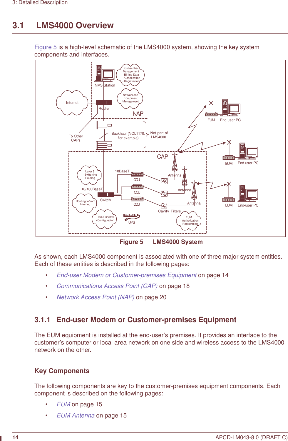
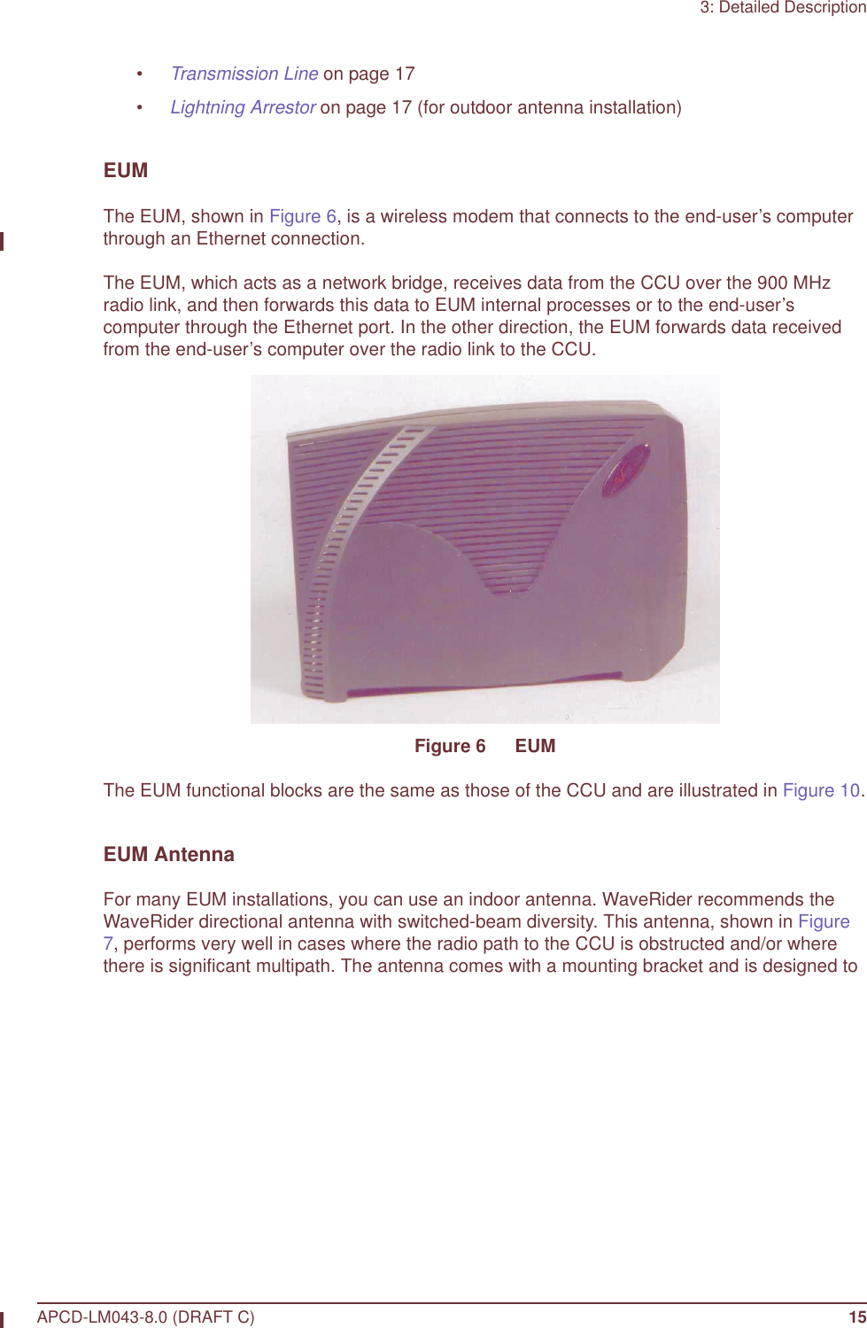
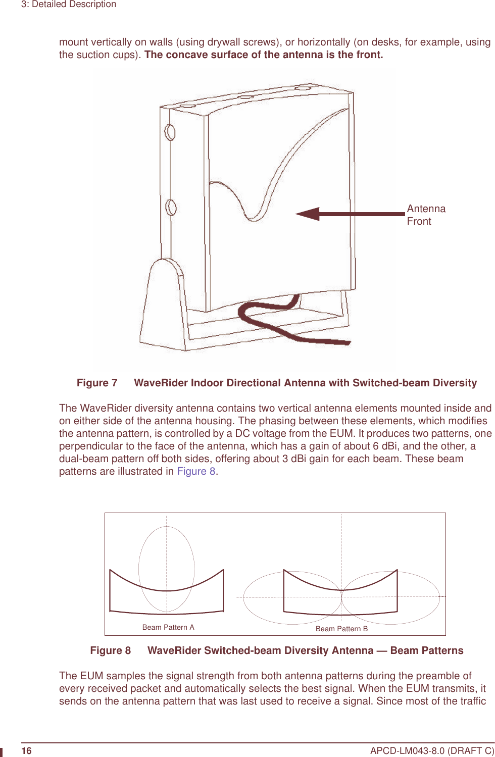
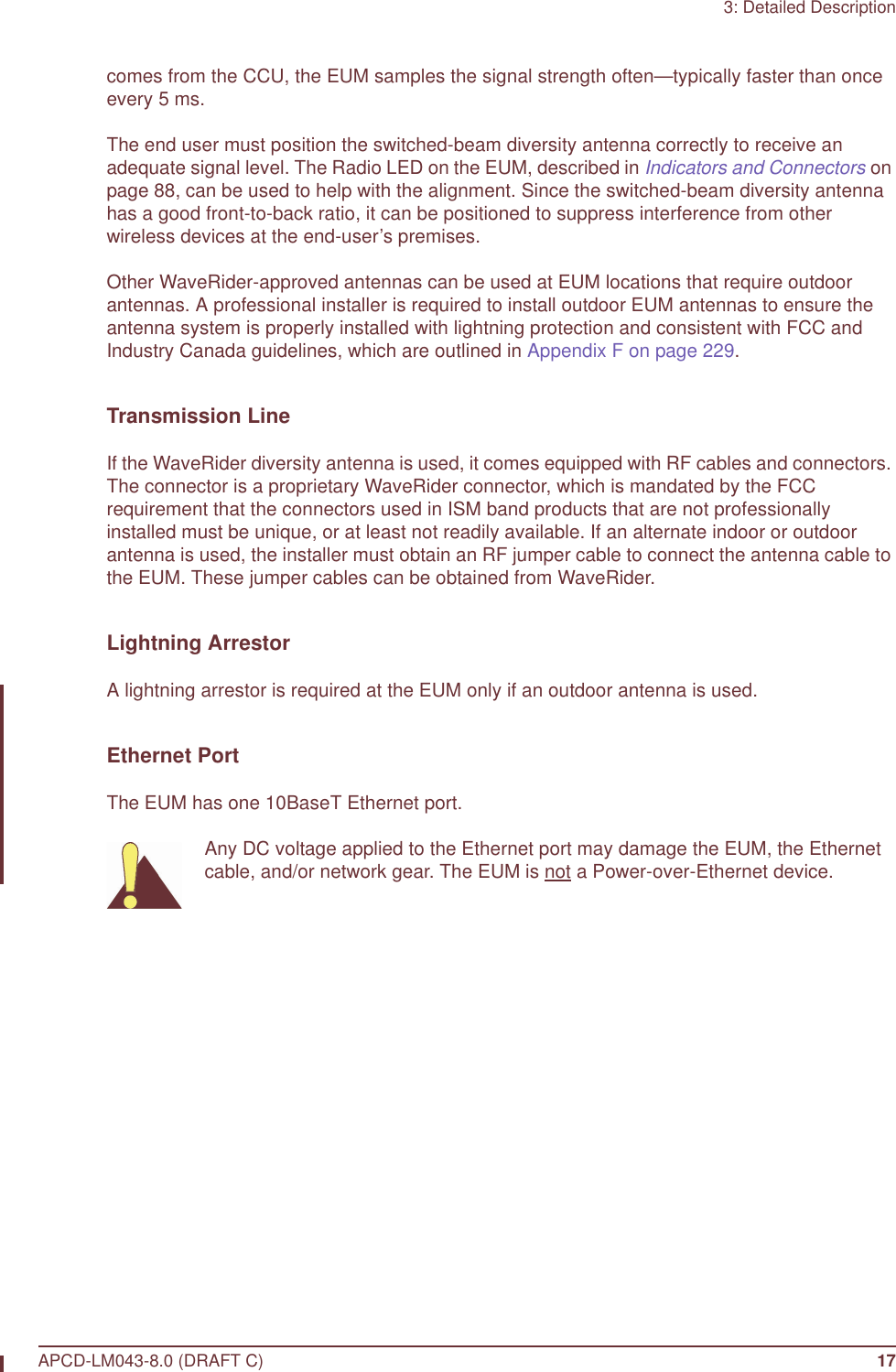
User Manual LMS4000 900MHz Part 1
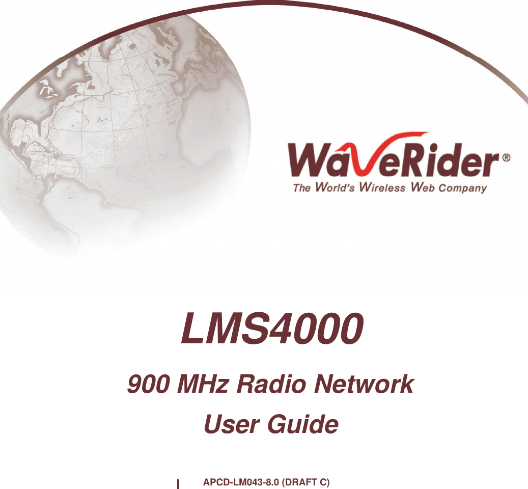


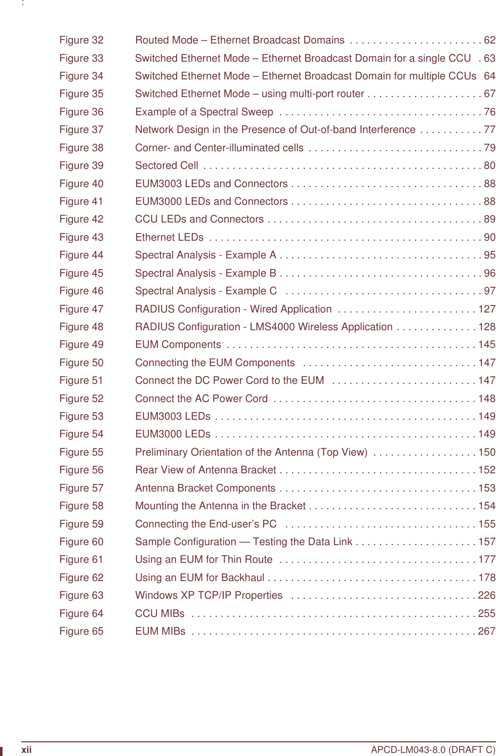
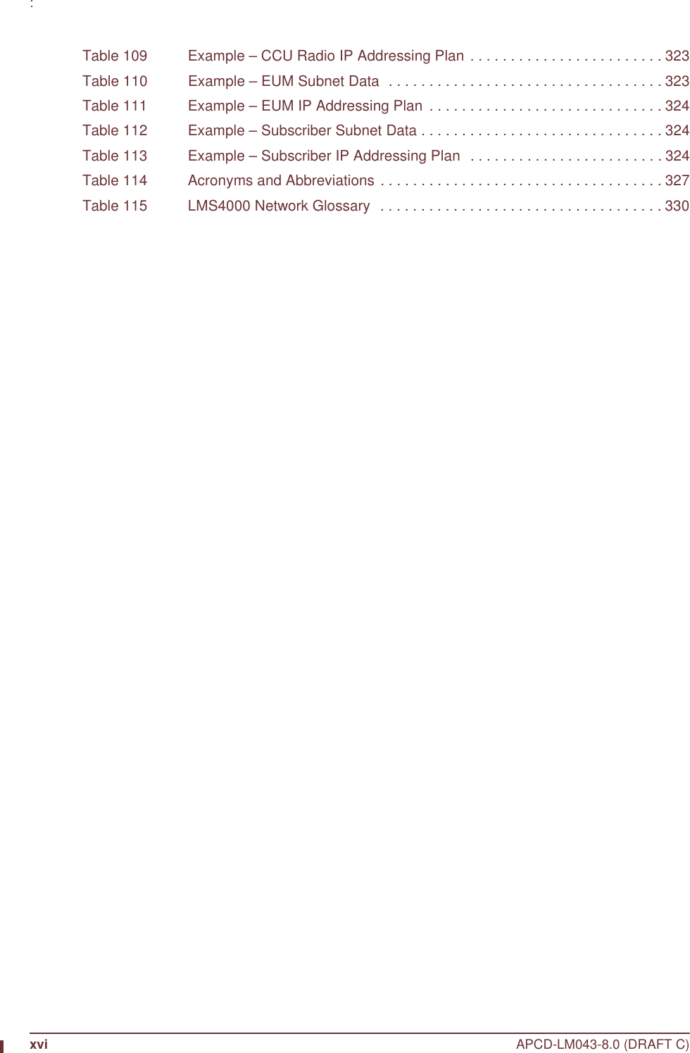
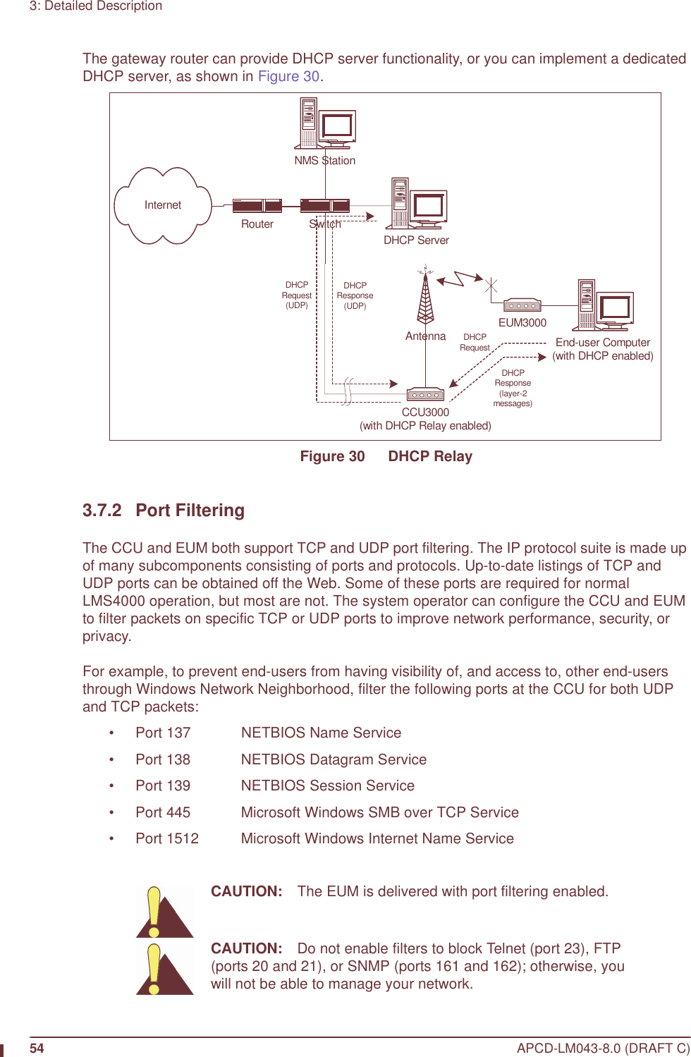
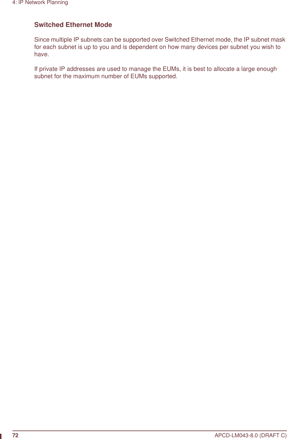
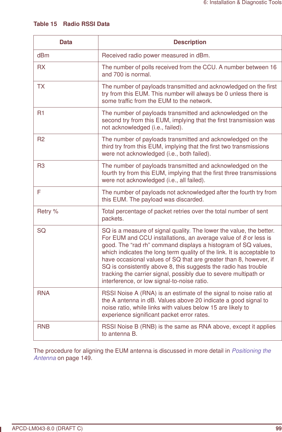
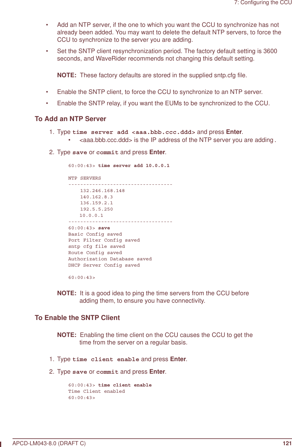
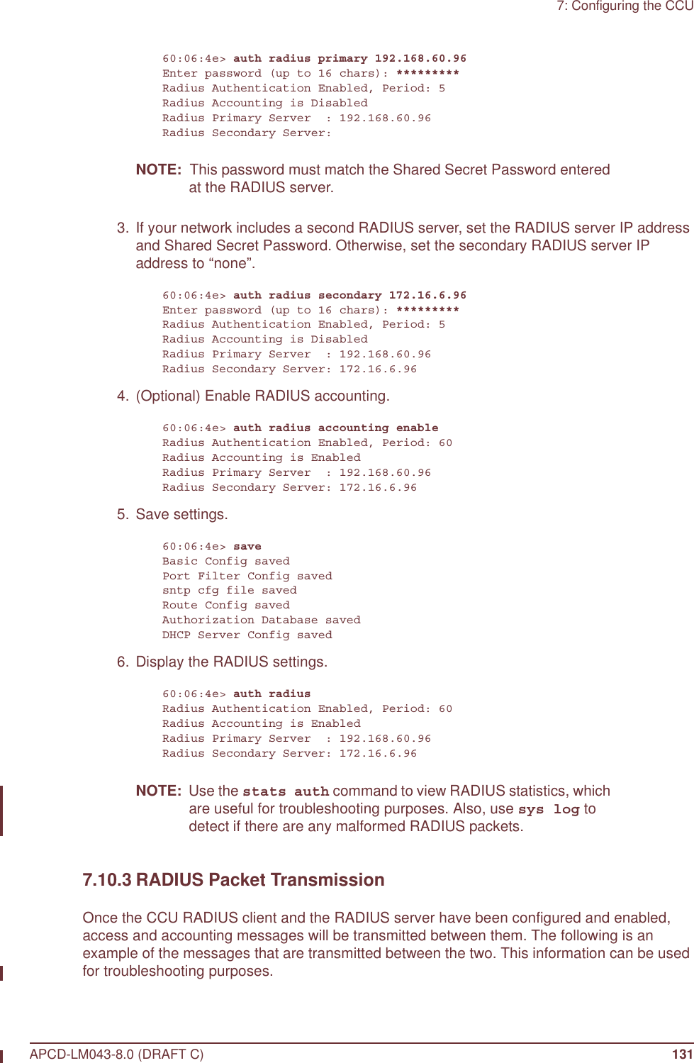
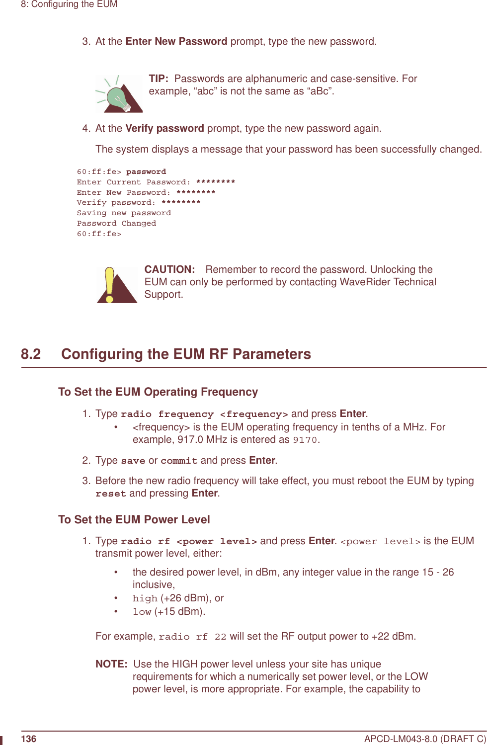
![: APCD-LM043-8.0 (DRAFT C) xxvRADIUS Authorization and Accounting SupportThe CCU now supports RADIUS authorization and accounting. When enabled, the CCU generates a RADIUS access-request message for each registered EUM on a periodic basis. The responses from the RADIUS server are used to maintain the authorization table.If accounting is enabled, the CCU sends periodic accounting updates to the RADIUS server for each registered EUM. These updates contain the Input and Output Packet and Byte counts for each EUM (Input is received from EUM, Output is transmitted to EUM).The following new RADIUS commands are available on the CCU:• auth radius disable• auth radius enable• auth radius primary• auth radius secondary• auth radius period• auth radius acct disable• auth radius acct enable• stats authAll RADIUS commands take effect immediately (without a reboot).RADIUS settings are stored in basic.cfg, with the shared secret passwords securely encrypted.The authorization table has a new column indicating whether an entry was entered from the CLI (static) or by a RADIUS response (radius). Non-response to RADIUS requests following the first is indicated in this column as well.Air Table Accounting InfoThe Tx-octet, Tx-packet, Rx-octet and Rx-packet counts maintained for RADIUS accounting are also printed out in the registration table as shown below:Maximum Associations: 75Deregistration Count: 8REGISTERED EUMs EUM ID GOS Class RSSI[dBm] Time[s] Rx-Octets Rx-Packets Tx-Octets Tx-Packets-------------------------------------------------------------------------------60:30:02 bronze -63 3 2177379 1471 42042 766 1 EUMs registered of 300 allowedLow Impact PollingThe polling algorithm has been modified to reduce the number of CCU transmissions under low load—and therefore the amount of time the spectrum is occupied—without reducing capacity or affecting latency. This improvement is achieved primarily by eliminating redundant random access polls.](https://usermanual.wiki/Vecima-Networks/EUM3004.User-Manual-LMS4000-900MHz-Part-1/User-Guide-372627-Page-25.png)

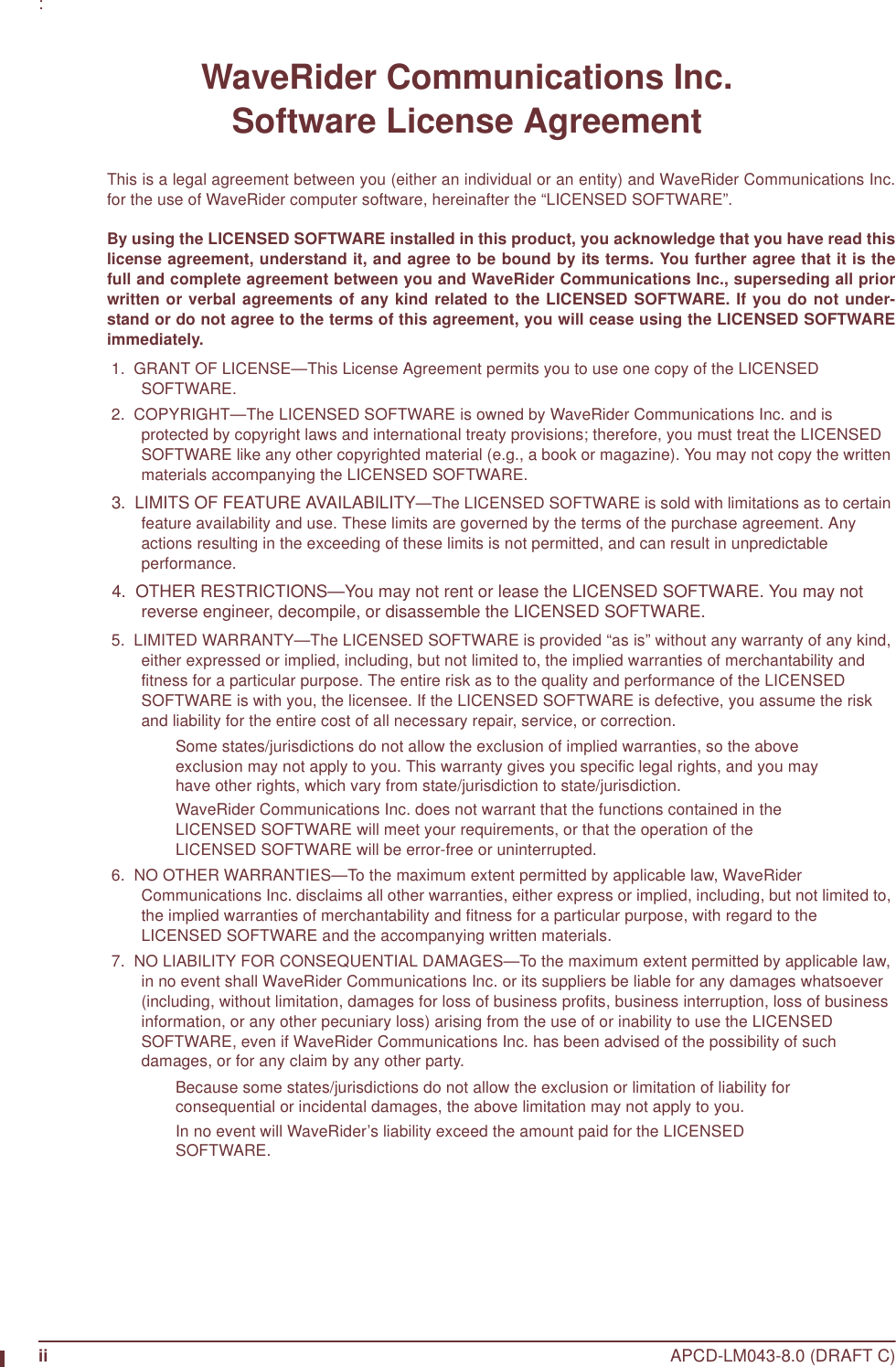
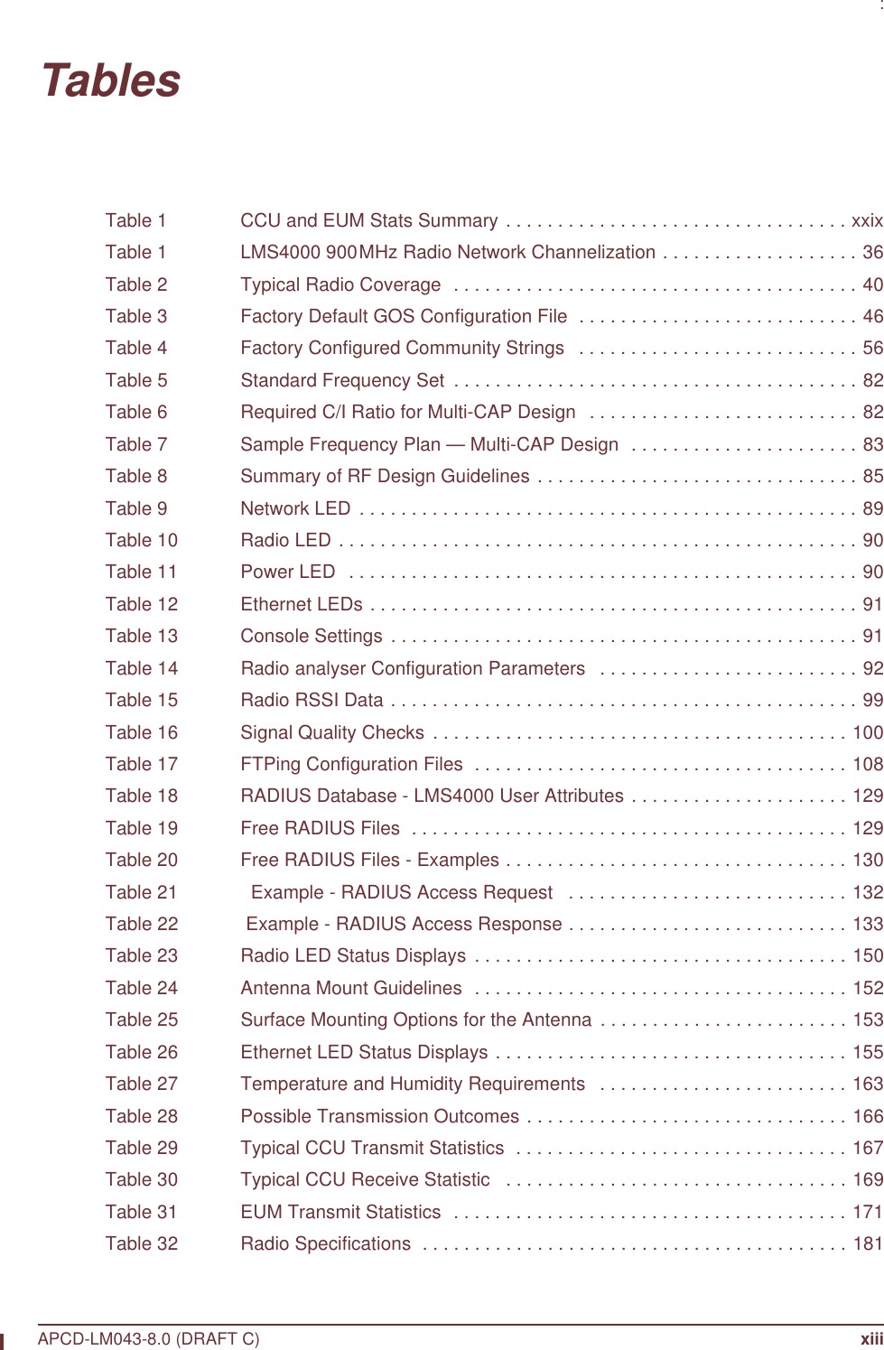
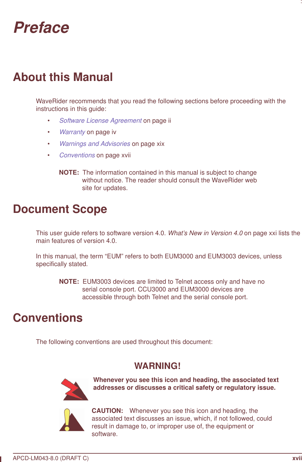
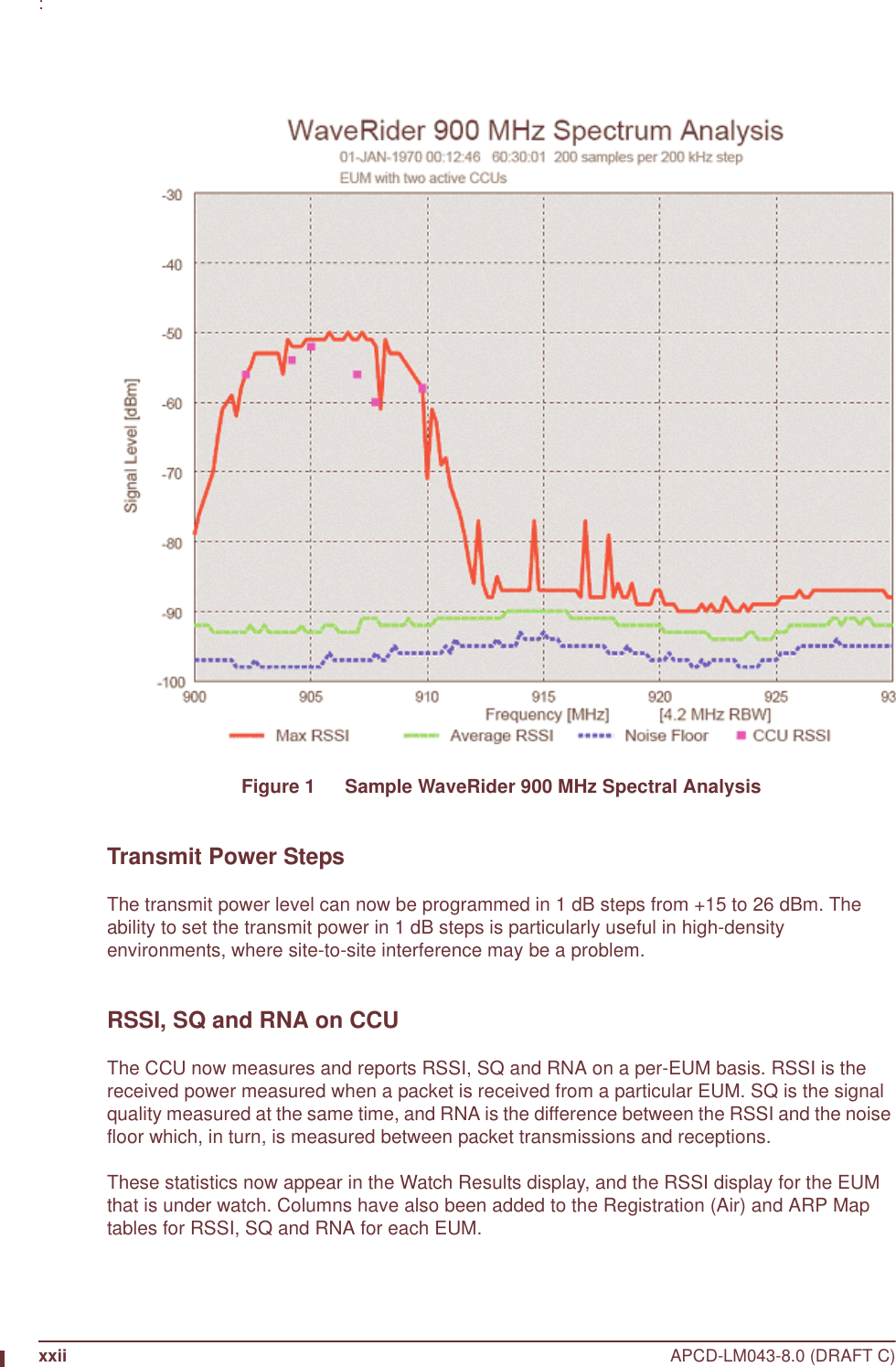
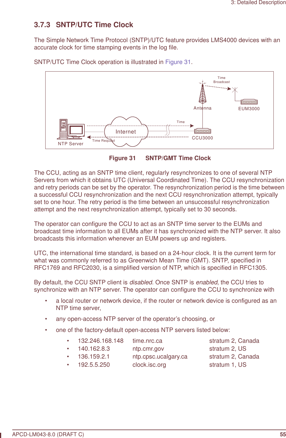
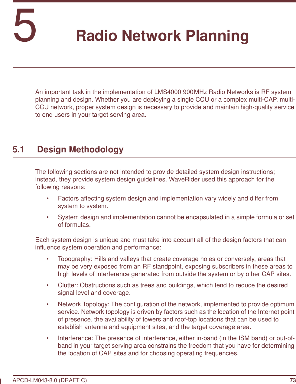
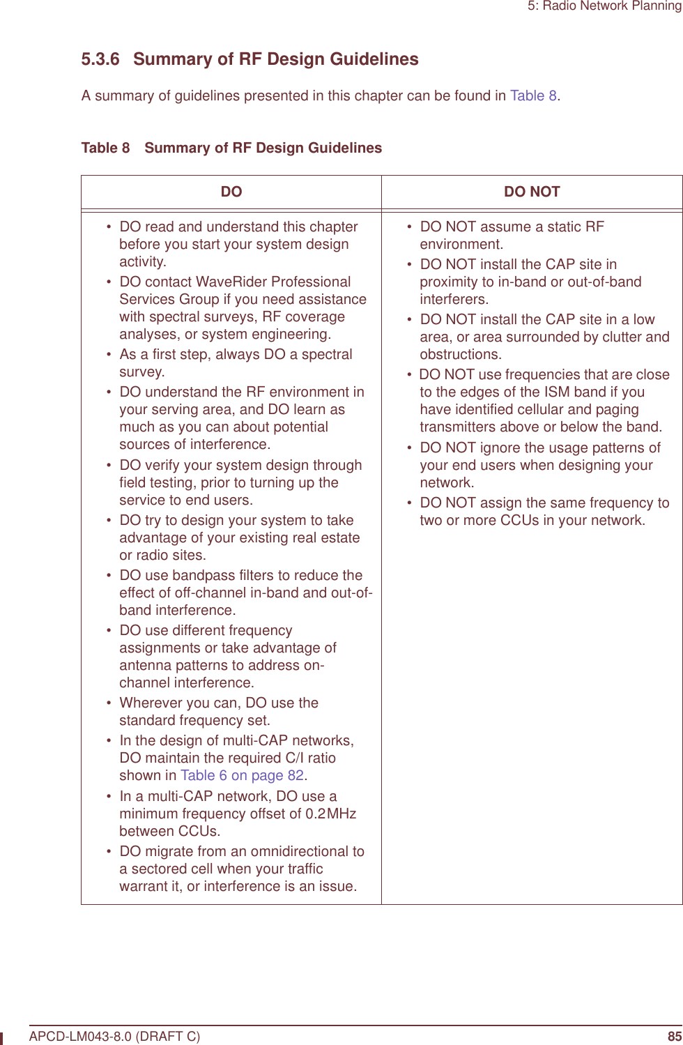
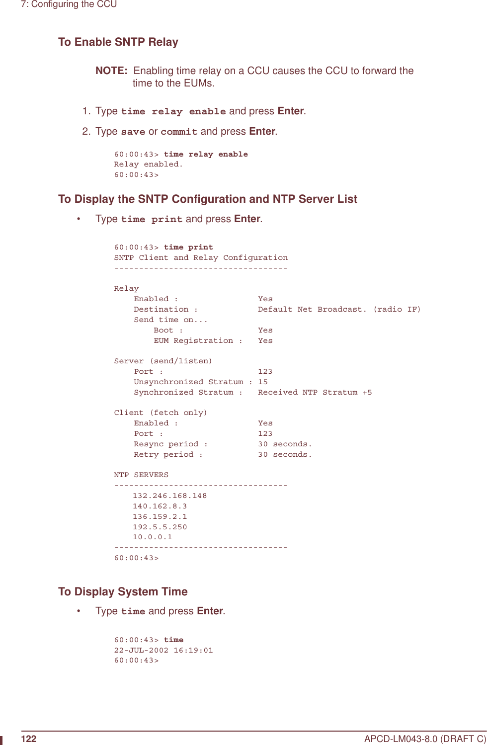
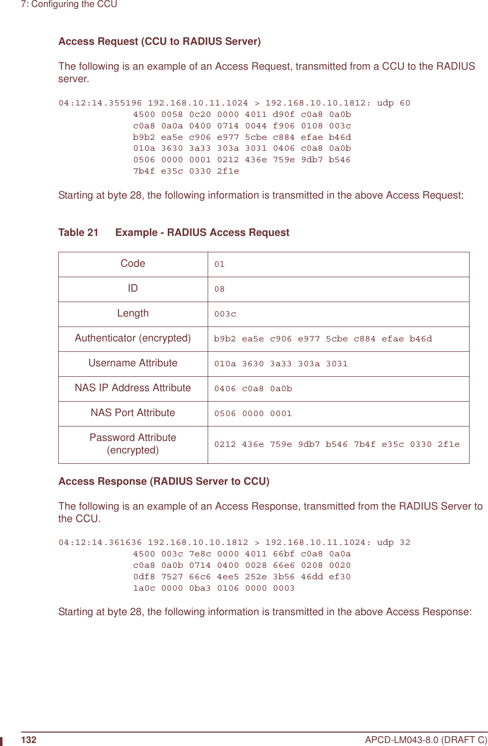
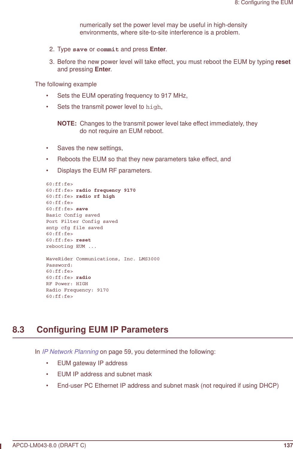
![xxx APCD-LM043-8.0 (DRAFT C): Radio Meter ImprovementThe radio meter command can now take an interval in seconds [1-30] as an argument and prints the metered values in rates per second, over that interval. The printouts continue at that interval until a key is pressed or the console times out. If no argument is given, the totals are printed. Only GOS classes that had some activity during the interval are displayed. Determining the Software Version on a CCU or EUMIf you are uncertain which software version you have installed on a CCU or EUM, use the following commands to determine the version.To Determine the Software Version on a CCU or EUM 1. Open the CCU or EUM console, as described in Access Interface on page 221. 2. At the prompt, type sys ver and press Enter.The software version is listed under the SA1110 heading. The Hardware Rev. is “A” if the device is a CCU3000 or EUM3000, and Hardware Rev. is “B” if the device is an EUM3003.60:03:3a> sys ver SA1110-------------------------------------------------CPU : WaveRider LMS3000 - ARMSA1110Hardware Rev. : AOS-BSP Version : 5.4/1.4Software Version: v4.0Software Build : 9 - Polled MACCreation Date : Mar 24 2003 ATMEL------------------------------------------------Vendor : WaveRiderFirmware Version: V2(p)1.2Hardware Rev. : V1(CCU) Bootrom-------------------------------------------------Copyright 1984-2002 WaveRider Communications, Inc.VxWorks version 1.4Bootrom release v4.0Created Mar 24 2003, 16:25:1060:03:3a>](https://usermanual.wiki/Vecima-Networks/EUM3004.User-Manual-LMS4000-900MHz-Part-1/User-Guide-372627-Page-30.png)

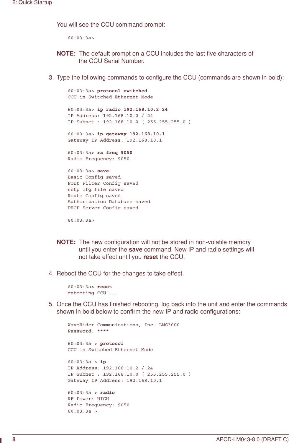


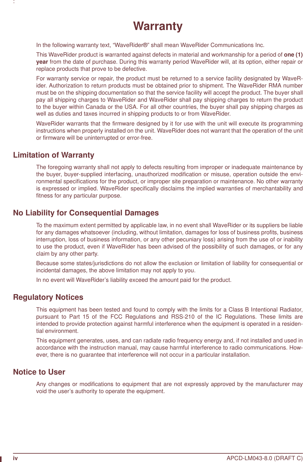
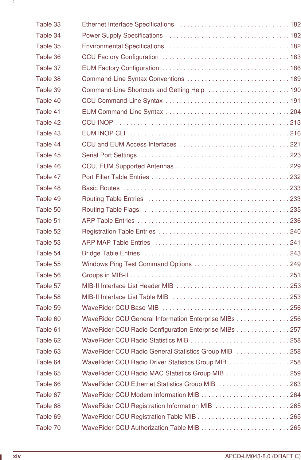
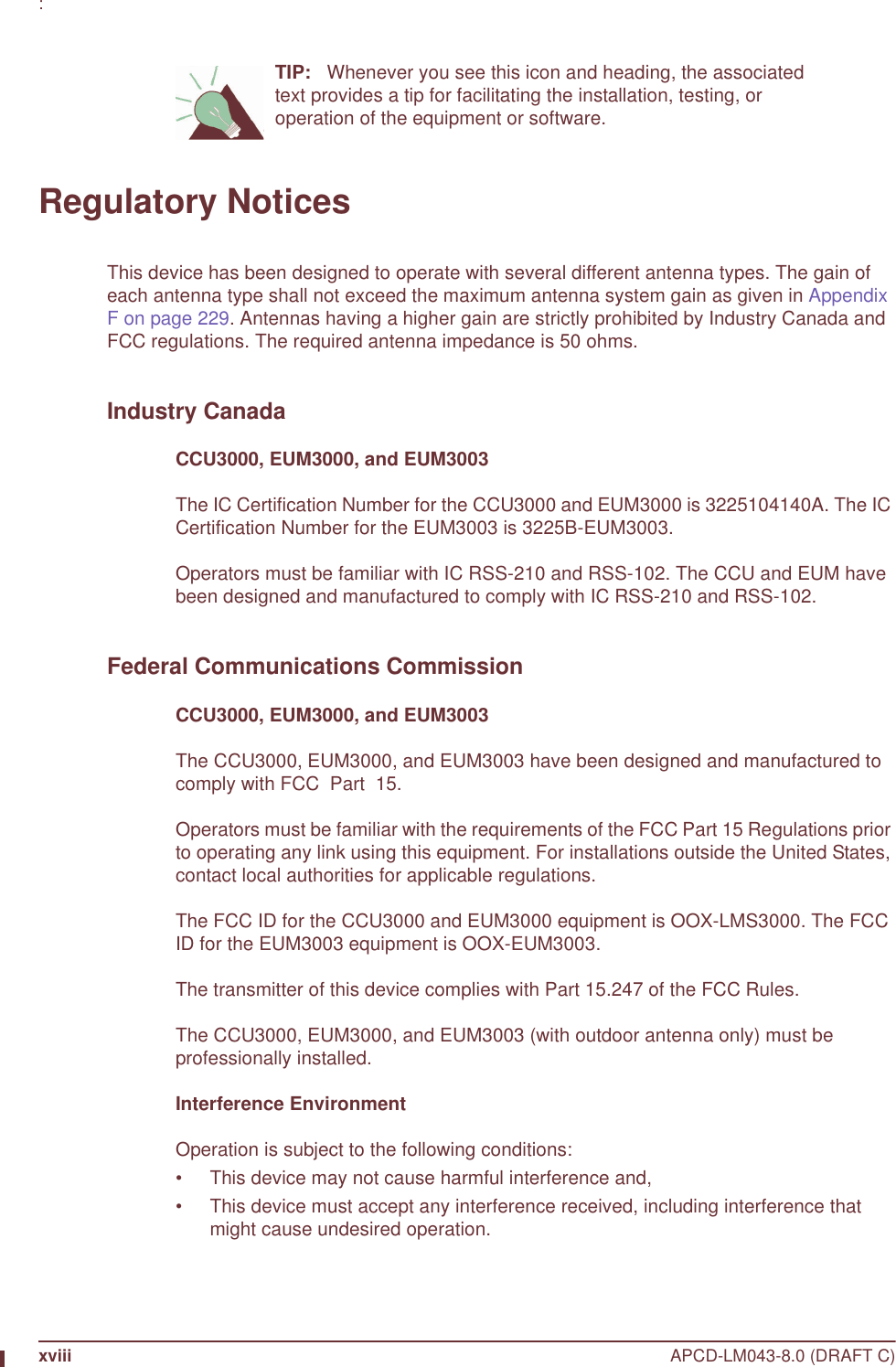
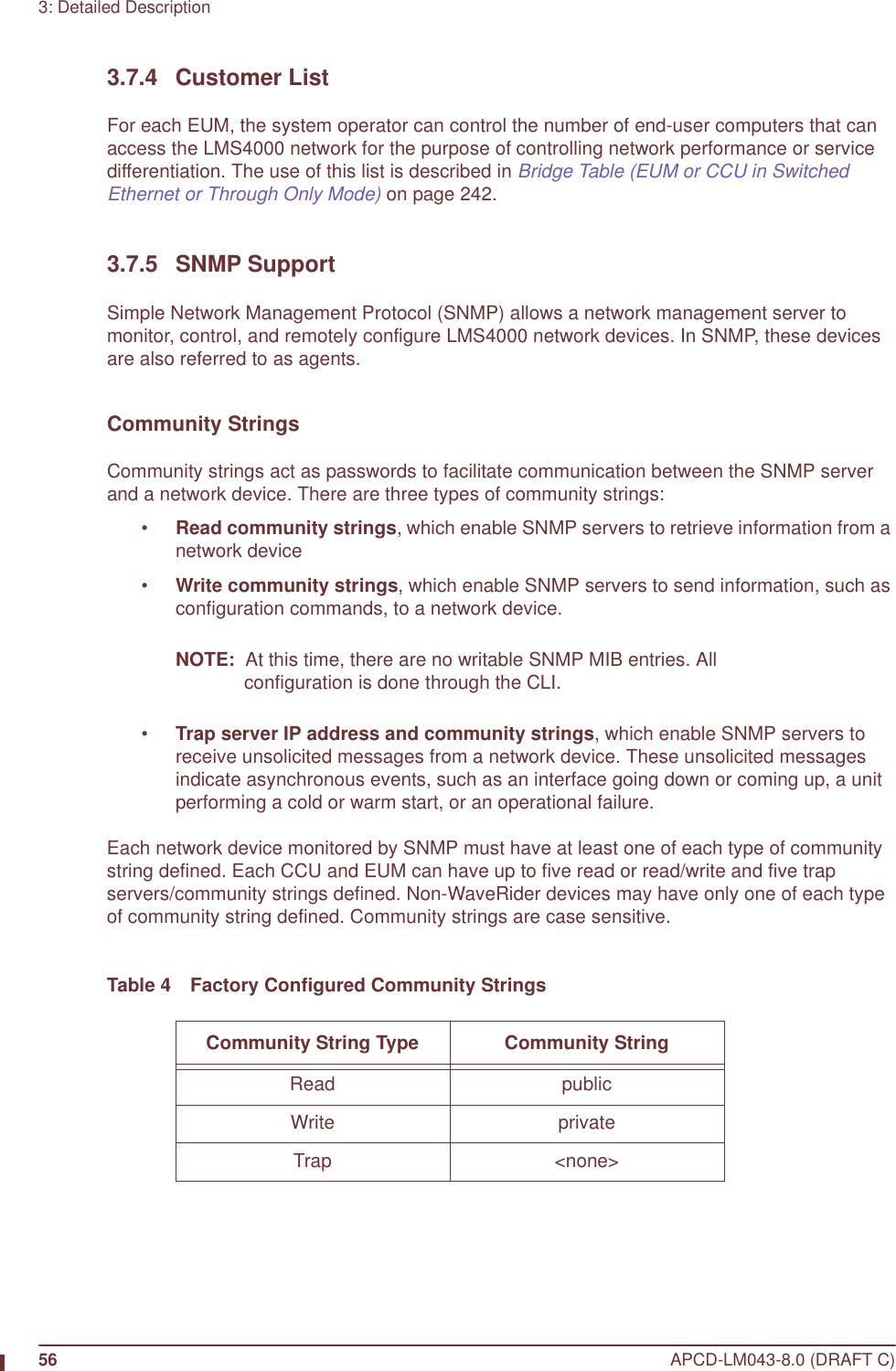
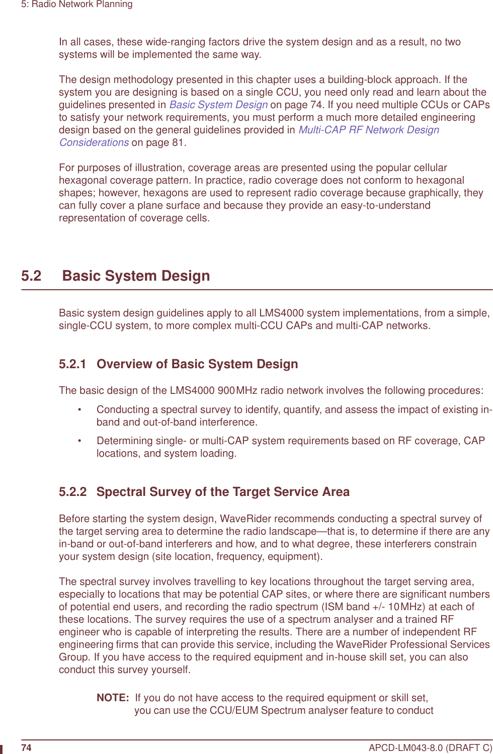
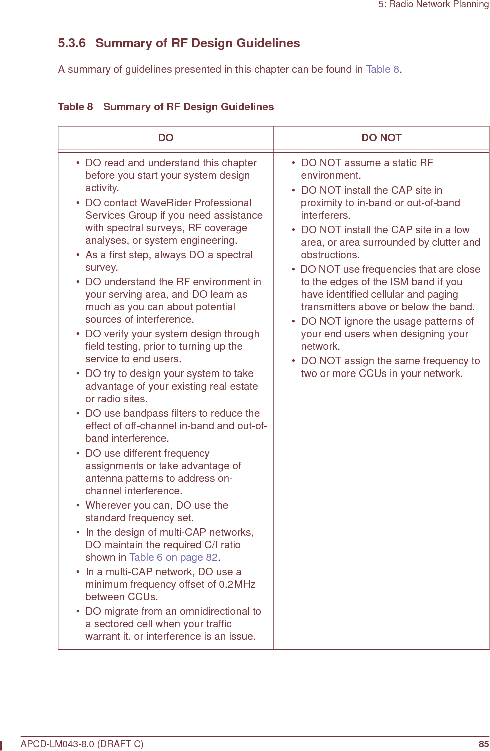
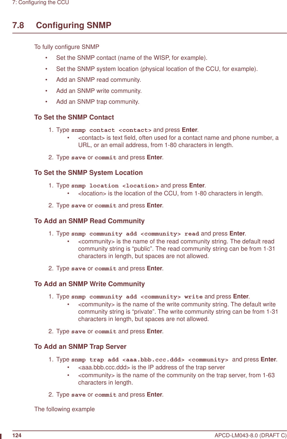
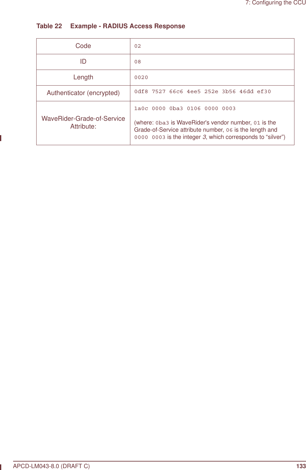
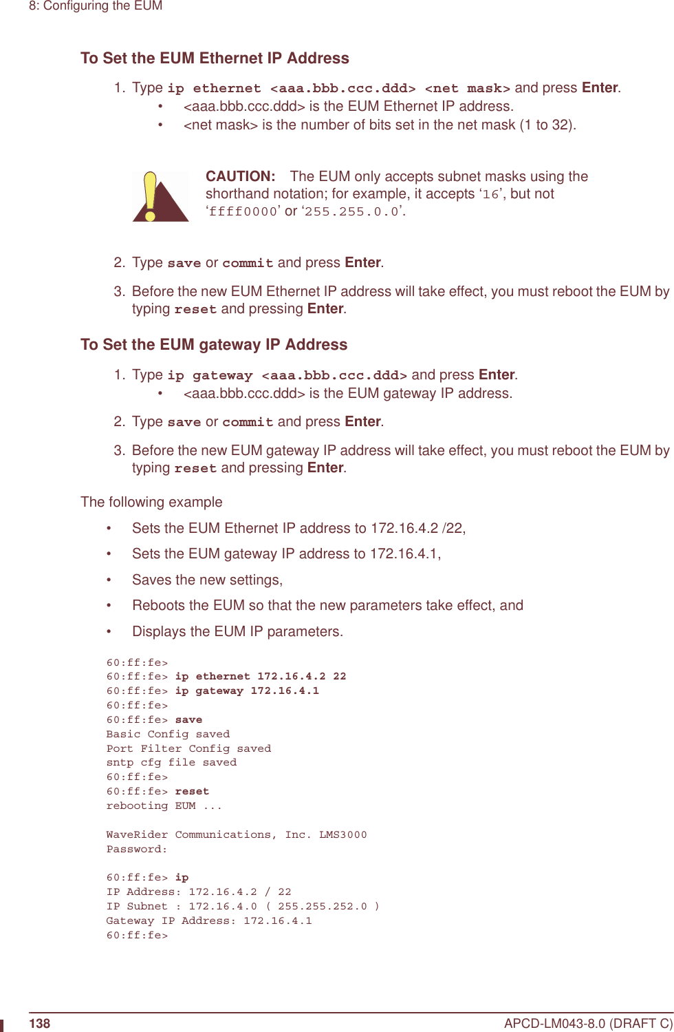
![46 APCD-LM043-8.0 (DRAFT C)3: Detailed DescriptionTable 3 Factory Default GOS Configuration FileNOTE: While recognizing that the performance of data transmission through packet radio networks is randomly dependent on many variables, typical FTP rates based on empirical data are included in the table to demonstrate the performance that the operator might expect on single, large FTP transfers using maximum-sized packets.There are several important observations that can be made about the above service-class descriptions:• All of the default service classes impose a limit on the maximum polling rate.• The Silver and Gold service classes have a lower bound on the polling rate (12 and 22 polls per second [pps] respectively). The Polling MAC treats this limit as a minimum committed level, which is subject to overall radio link capacity.• In determining the order and frequency with which to poll EUMs, the CCU first tries to ensure all associated EUMs are polled no more frequently than the maximum service class polling rate, and no less frequently than the minimum service class polling rate.• As the system usage increases, the end-user throughput in all classes decreases from the maximum. Bronze users see the largest reduction, then Gold users, and then Best Effort users. When all users have been reduced to 256 kbps (the minimum threshold for Gold), the next reduction will be shared by the Best Effort, Bronze, and Silver class users (Gold will not be reduced further), until the minimum threshold for Silver is reached. After this, if further reductions are required, this reduction would be shared equally between the Best Effort and Bronze users. In practice, the bursty nature of Internet usage is such that this methodical reduction in throughput is not apparent to the end-user, and these variations in service level tend to be instantaneous and transitory. Overall, end-users tend to see a relatively high average throughput consistent with their assigned GOS class, as is shown later in detailed simulation results based on real user data.Service Class Polling Rate (polls/second) FTP Rate (see note) Operator AssignedBest Effort 1 - 34 0 - 384 kbps YesBronze 1 - 90 0 - 1024 kbps YesSilver 12 - 22 128 - 256 kbps YesGold 22 - 46 256 - 512 kbps YesBroadcast Varies with channel load,from 16 to 29 Not applicable NoDenied 0 0 Yes](https://usermanual.wiki/Vecima-Networks/EUM3004.User-Manual-LMS4000-900MHz-Part-1/User-Guide-372627-Page-76.png)


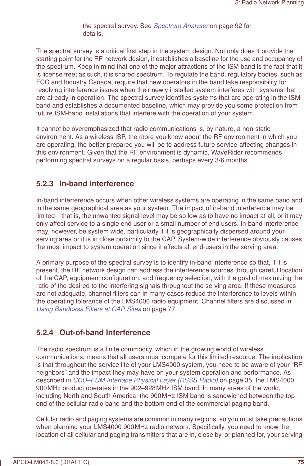
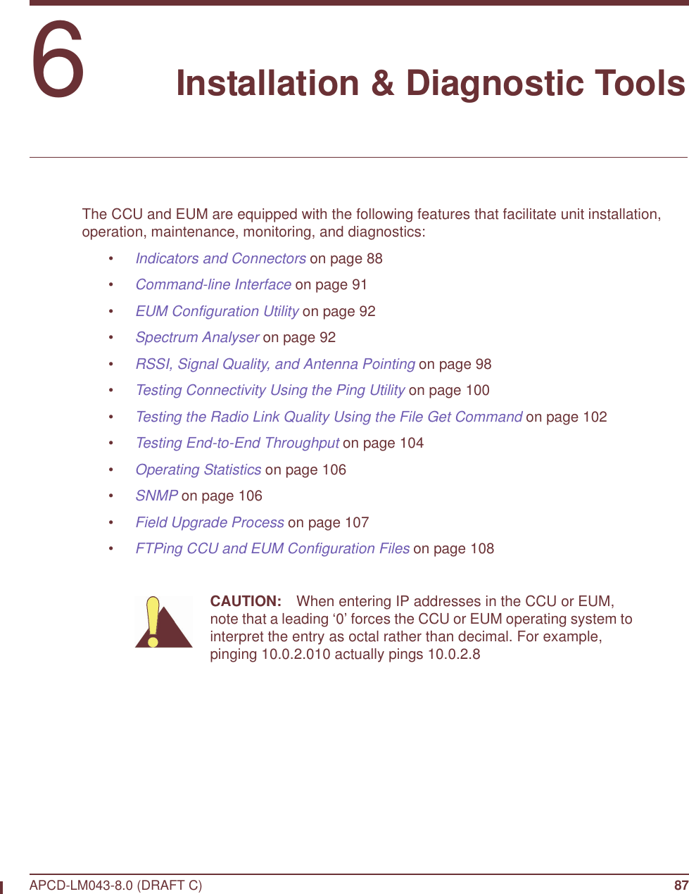


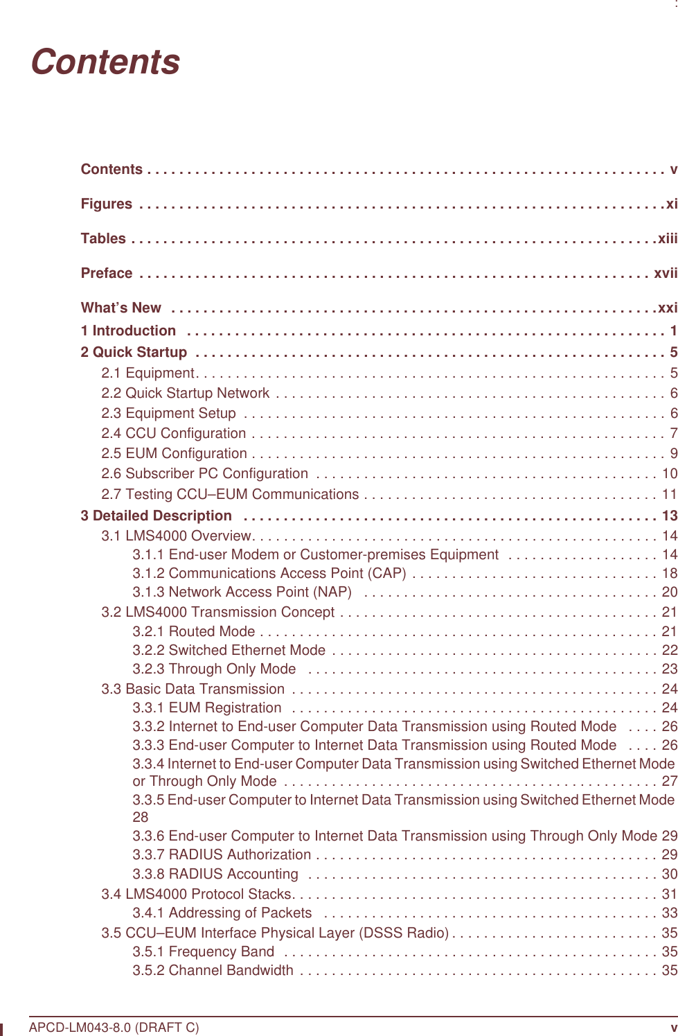
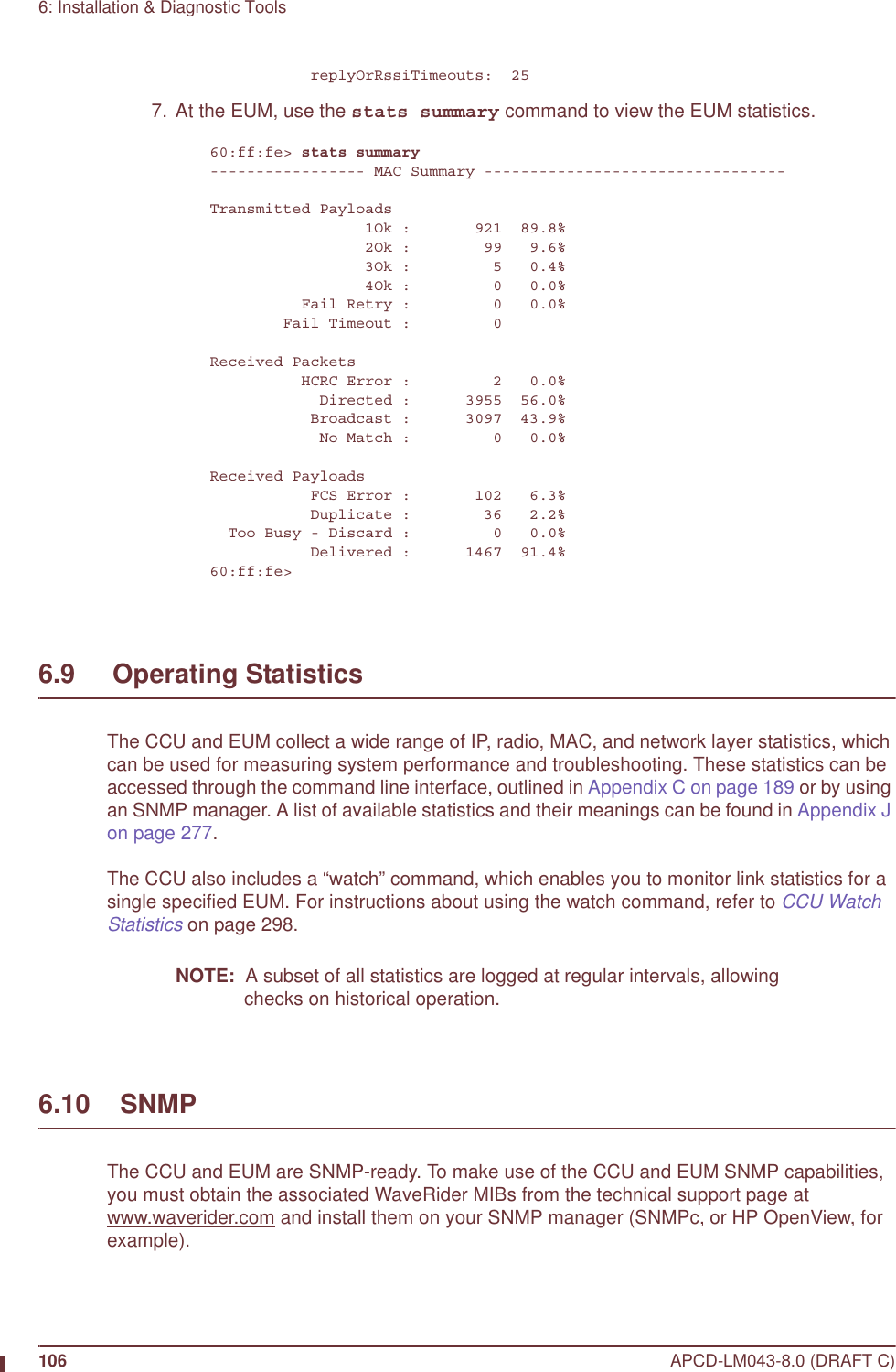
![6: Installation & Diagnostic ToolsAPCD-LM043-8.0 (DRAFT C) 103file transfer completeTransfered "/tffs0/null" Okay.60:ff:fe>NOTE: For more information about the “file get” command, refer to Appendix C on page 189. 4. At the CCU, use the watch command to view the EUM watch statistics.60:03:3a> watch The EUMID under watch is: 60:ff:fe Grade of service: be RSSI [dBm]: -24 Time since last payload: 0 Input Octets: 2378095 Input Packets: 3370 Output Octets: 2731787 Output Packets: 3344 rxPktsDirected: 44743 rxPktsBroadcast: 19 rxPktsDuplicate: 0 rxPktsFCSFail: 2 rxPayloadsDelivered: 2584 rxPktsEmpty: 42176 txPkts: 44767 txPktsEmpty: 42154 txPayloads: 2613 txPayloads1Ok: 2585 txPayloads2Ok: 14 txPayloads3Ok: 0 txPayloads4Ok: 0 txPayloadsFailRetry: 0 txPayloadsFailTimeout: 0 txPayloadsFailQueueTooLong: 0 replyOrRssiTimeouts: 25 5. At the EUM, use the stats summary command to view the EUM statistics60:ff:fe> stats summary----------------- MAC Summary ---------------------------------Transmitted Payloads 1Ok : 921 89.8% 2Ok : 99 9.6% 3Ok : 5 0.4% 4Ok : 0 0.0% Fail Retry : 0 0.0% Fail Timeout : 0Received Packets HCRC Error : 2 0.0% Directed : 3955 56.0% Broadcast : 3097 43.9% No Match : 0 0.0%Received Payloads FCS Error : 102 6.3% Duplicate : 36 2.2% Too Busy - Discard : 0 0.0% Delivered : 1467 91.4%60:ff:fe>](https://usermanual.wiki/Vecima-Networks/EUM3004.User-Manual-LMS4000-900MHz-Part-1/User-Guide-372627-Page-133.png)

![6: Installation & Diagnostic ToolsAPCD-LM043-8.0 (DRAFT C) 105ftp> hashHash mark printing On ftp: (2048 bytes/hash mark) .ftp> binary200 Type set to I, binary modeftp> get null200 Port set okay150 Opening BINARY mode data connection##########################################################################################################################################################################################################################226 Transfer completeftp: 463713 bytes received in 10.80Seconds 42.96Kbytes/sec.ftp>bye221 Bye...See you later. 5. Enter the following commands to put the null file to the CCU.Connected to <aaa.bbb.ccc.ddd>.220 FTP server readyUser (<aaa.bbb.ccc.ddd>:(none)):331 Password requiredPassword:230 User logged inftp> hashHash mark printing On ftp: (2048 bytes/hash mark) .ftp> binary200 Type set to I, binary modeftp> put null200 Port set okay150 Opening BINARY mode data connection##########################################################################################################################################################################################################################226 Transfer completeftp: 463713 bytes sent in 8.30Seconds 55.86Kbytes/sec.ftp>bye221 Bye...See you later. 6. At the CCU, use the watch command to view the EUM watch statistics.60:03:3a> watch The EUMID under watch is: 60:ff:fe Grade of service: be RSSI [dBm]: -24 Time since last payload: 0 Input Octets: 2378095 Input Packets: 3370 Output Octets: 2731787 Output Packets: 3344 rxPktsDirected: 44743 rxPktsBroadcast: 19 rxPktsDuplicate: 0 rxPktsFCSFail: 2 rxPayloadsDelivered: 2584 rxPktsEmpty: 42176 txPkts: 44767 txPktsEmpty: 42154 txPayloads: 2613 txPayloads1Ok: 2585 txPayloads2Ok: 14 txPayloads3Ok: 0 txPayloads4Ok: 0 txPayloadsFailRetry: 0 txPayloadsFailTimeout: 0 txPayloadsFailQueueTooLong: 0](https://usermanual.wiki/Vecima-Networks/EUM3004.User-Manual-LMS4000-900MHz-Part-1/User-Guide-372627-Page-135.png)


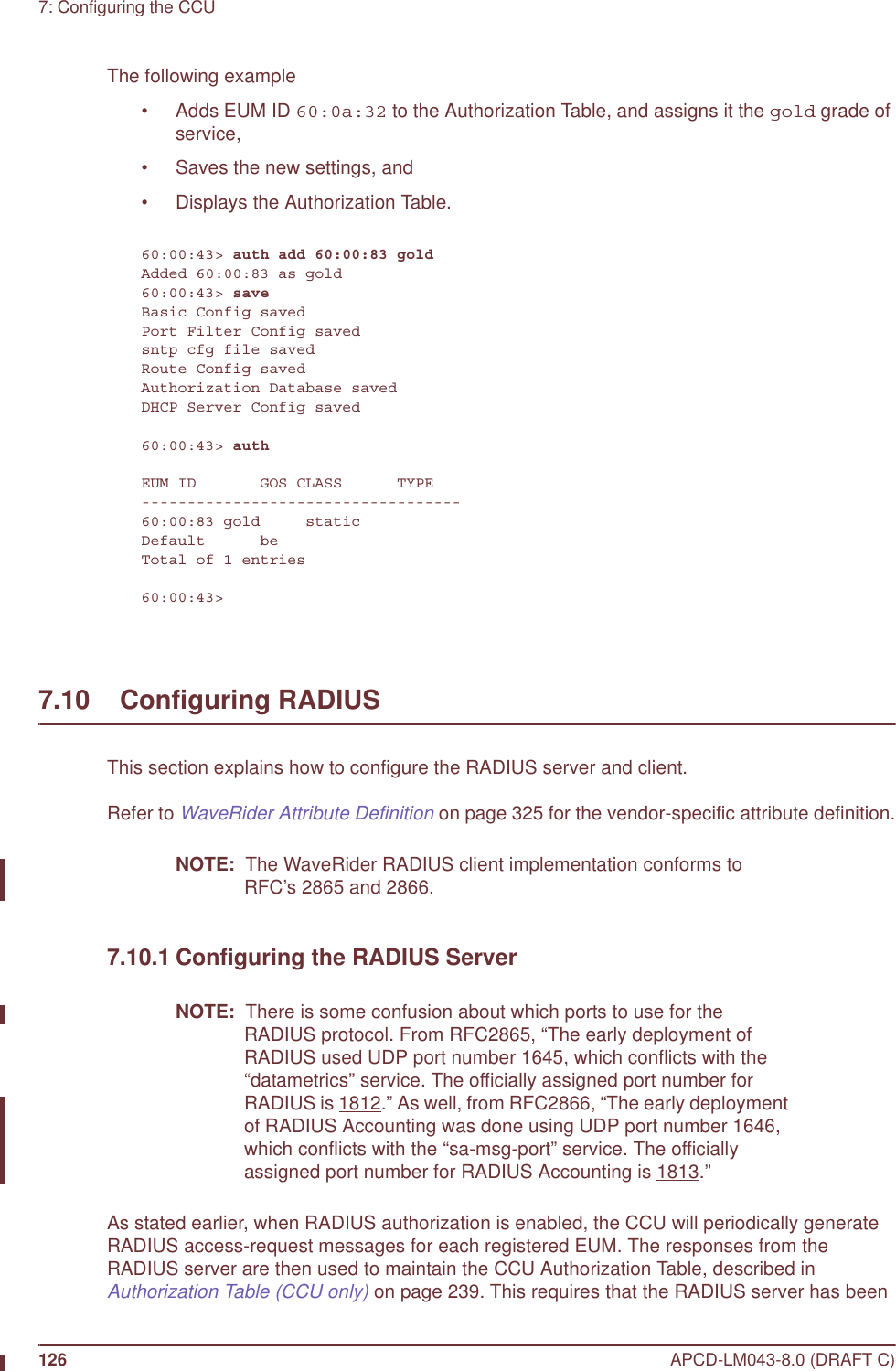

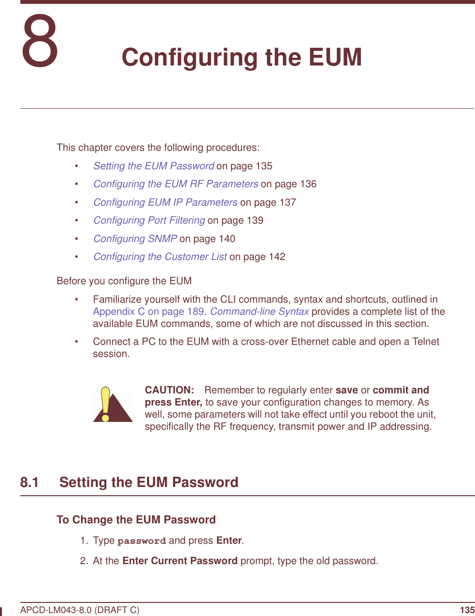
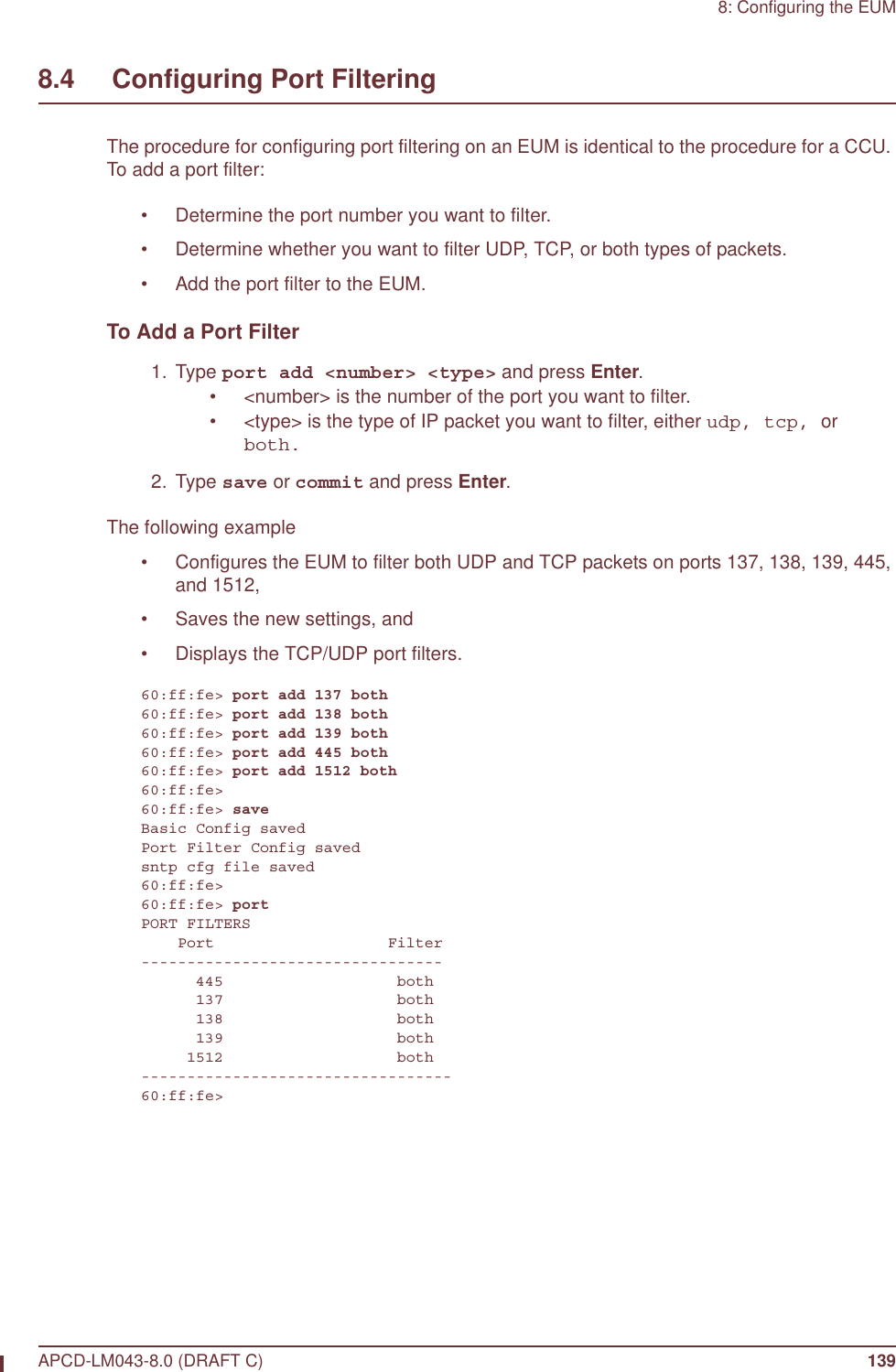

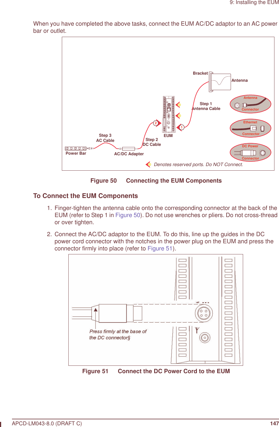
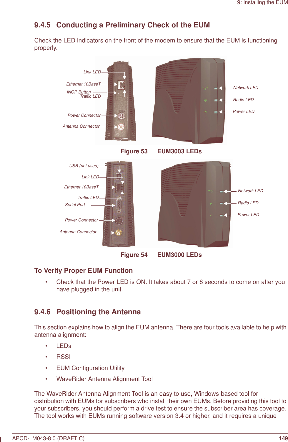
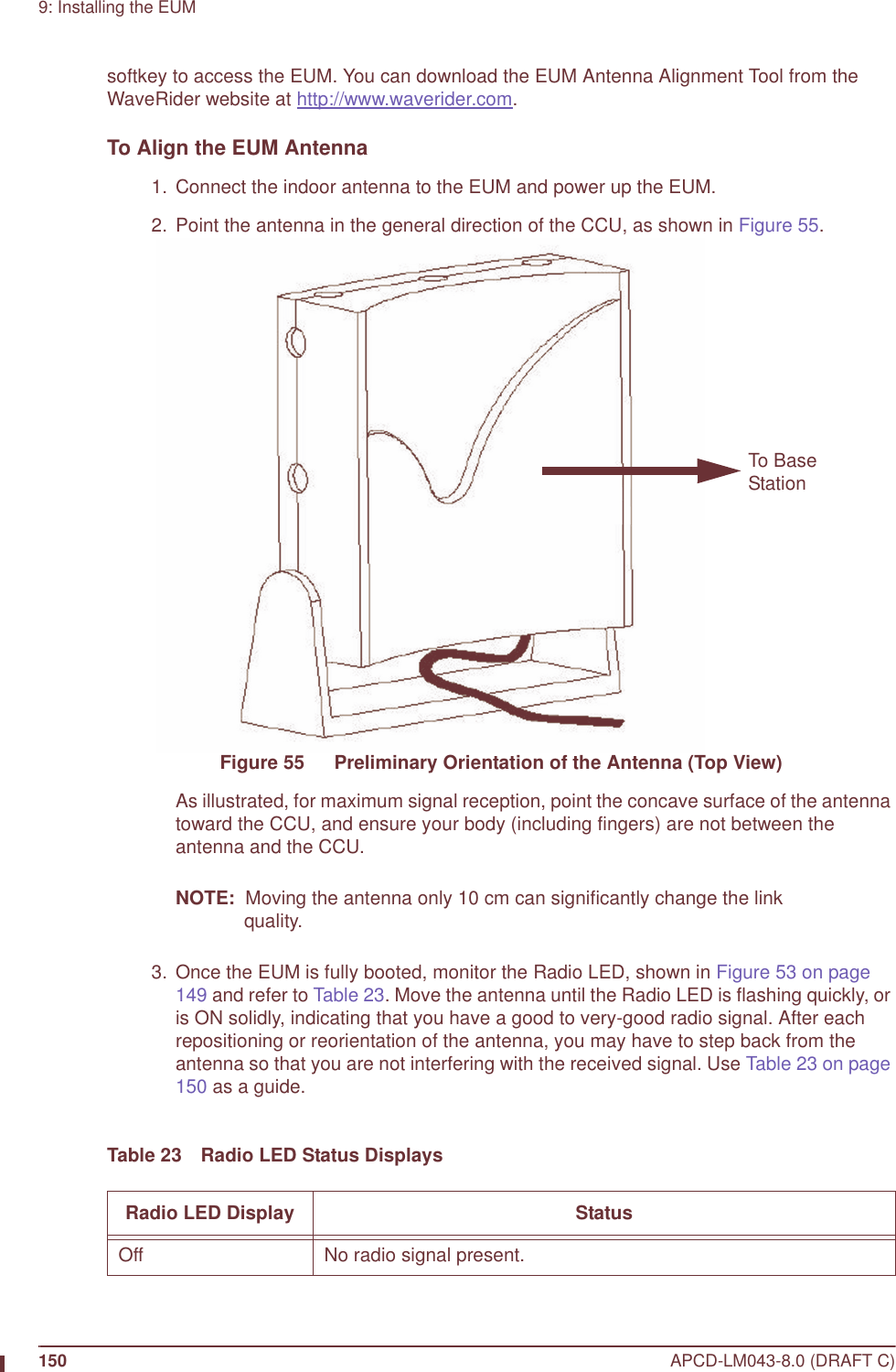
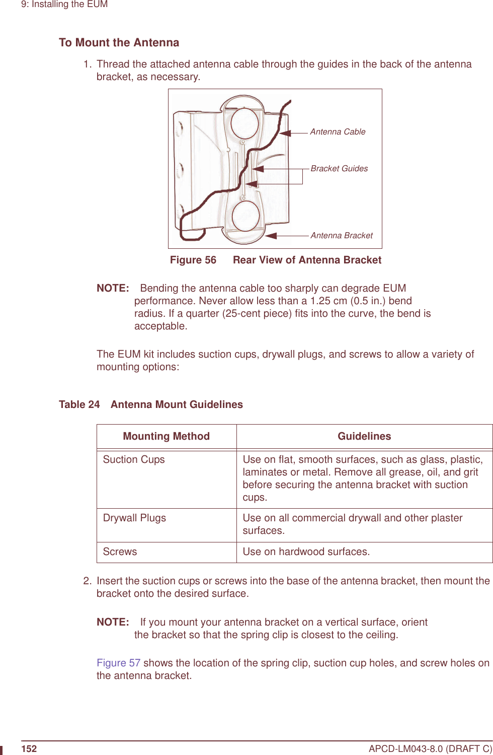
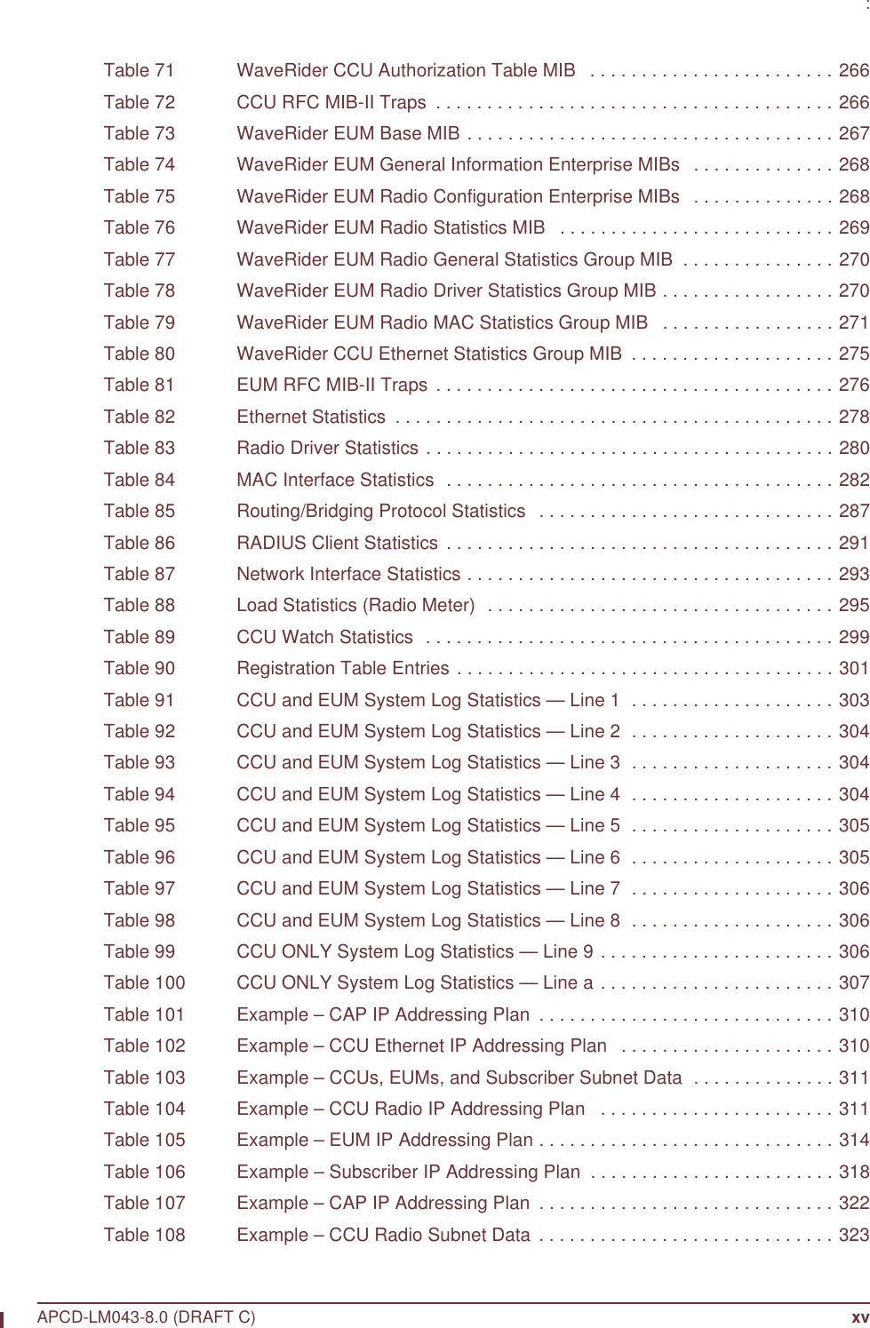
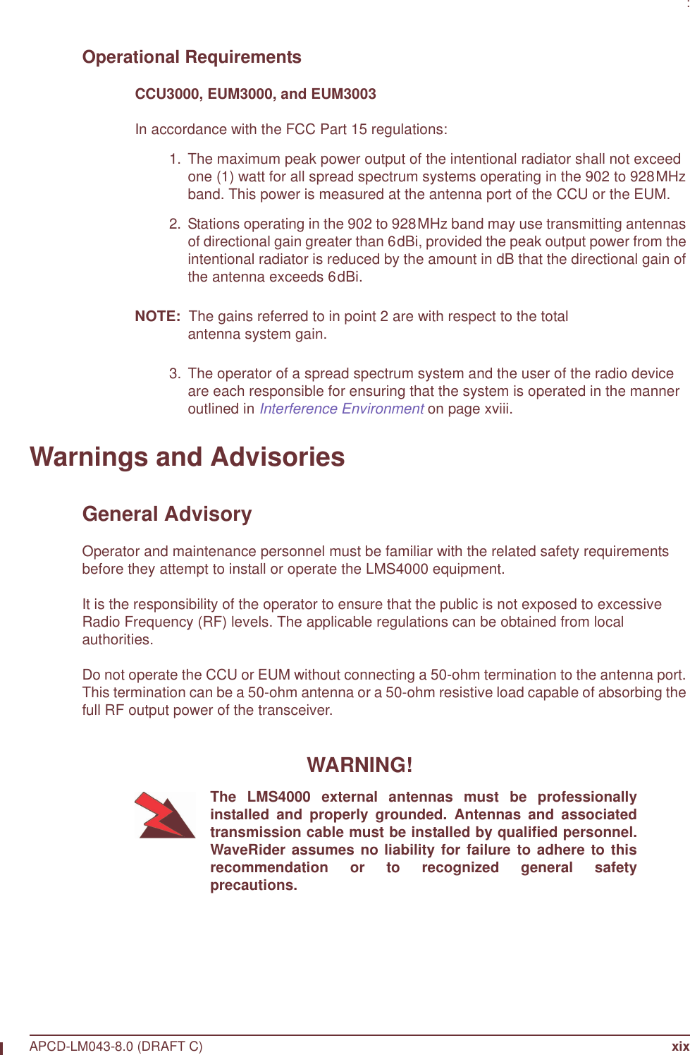
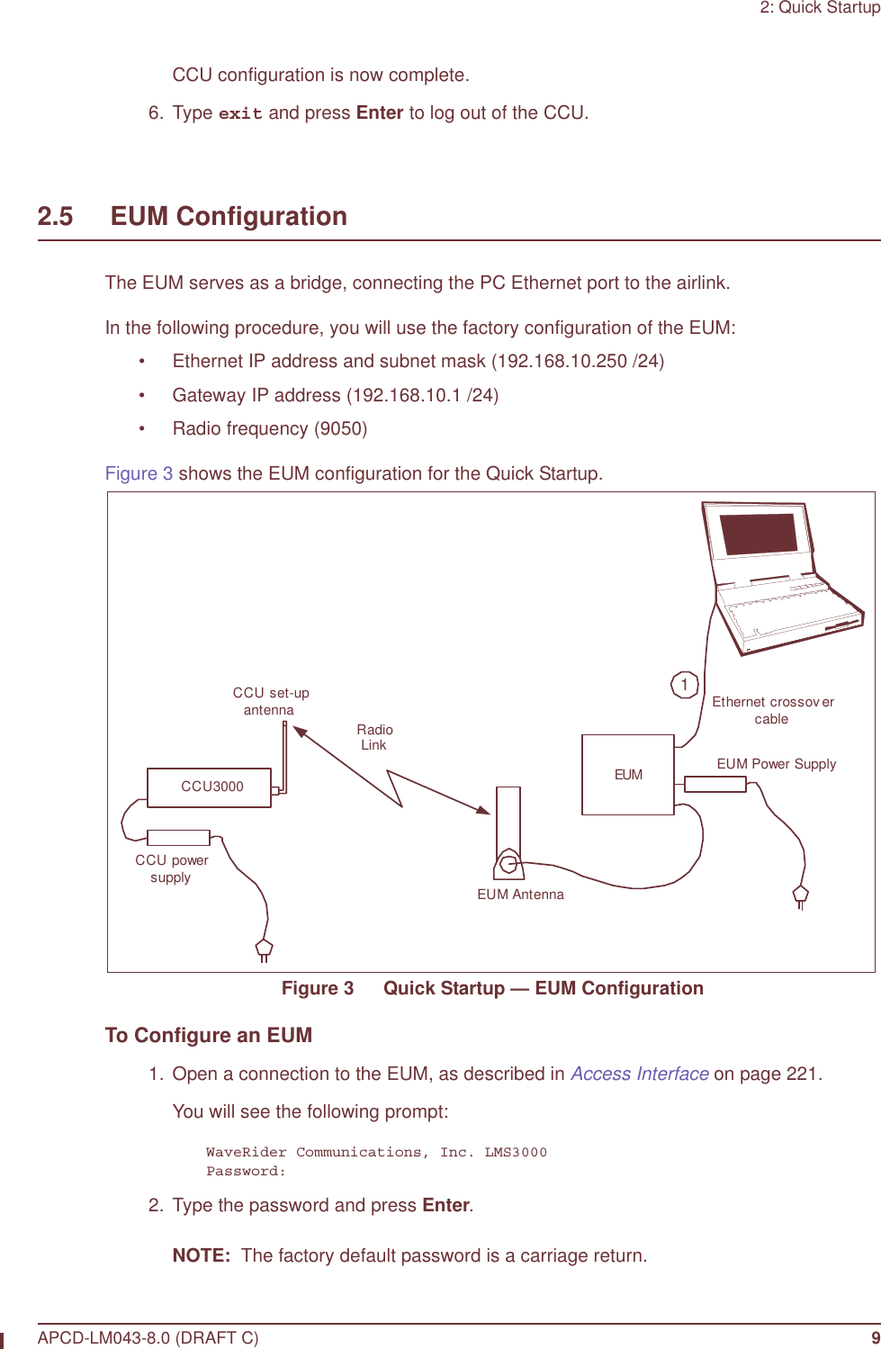
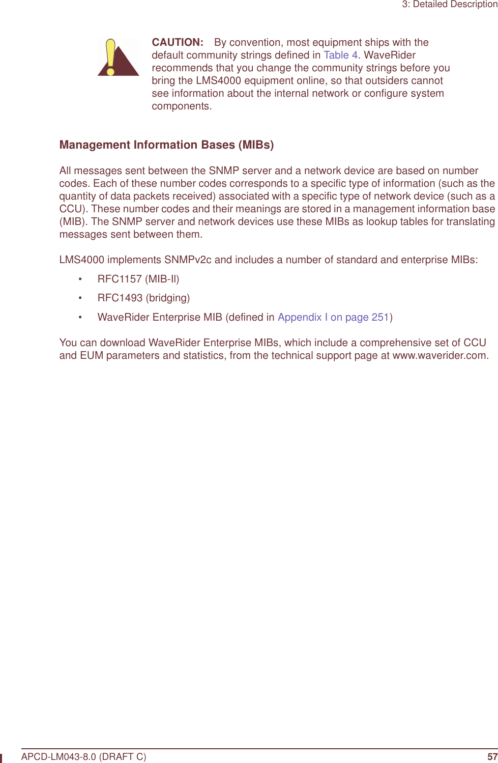
![9: Installing the EUMAPCD-LM043-8.0 (DRAFT C) 151 4. If the best location produces a Fast Flash or ON Solid Radio LED, then the received signal level is good to excellent, and this is a good location to install the antenna. 5. If the Radio LED is off or flashes slowly, then the antenna should be moved to a better location. Keep in mind that the antenna and EUM do not have to be located in the same room as the end-user’s PC since up to 100m (300ft.) of CAT5 data cable with a ferrite bead can connect the EUM to the PC. To attain the best possible signal below the Fast Flash LED level, turn on the Continuous RSSI through the command-line interface, as follows:60:ff:fe> rad rssiPress any key to stopRSSI[dBm] RX; TX; R1; R2; R3; F;Retry%; SQ; RNA; RNBRSSI: -36 0; 0; 0; 0; 0; 0; 0; 7; 71; 71RSSI: -36 18; 2; 0; 0; 0; 0; 0; 5; 72; 71RSSI: -36 18; 2; 0; 0; 0; 0; 0; 8; 73; 72RSSI: -36 18; 3; 0; 0; 0; 0; 0; 6; 73; 72RSSI: -37 18; 2; 0; 0; 0; 0; 0; 5; 72; 72RSSI: -37 18; 2; 0; 0; 0; 0; 0; 6; 71; 71RSSI: -36 18; 2; 0; 0; 0; 0; 0; 5; 72; 7260:ff:fe> 6. Adjust the antenna location and pointing for maximum RSSI. You may need to adjust the antenna and then step back each time to read the RSSI, so you do not obstruct the signal from the CCU. 7. Once you have found a good location, you are ready to mount the antenna, as described in section 9.4.7, Mounting the Antenna.9.4.7 Mounting the AntennaThe antenna bracket is designed to accommodate the RF cable and act as a strain relief.Slow Flash ON/OFF 0.83 times per second. The signal strength is poor to marginal.Fast Flash ON/OFF 2.5 times per second. The signal strength is good.Solid On The signal strength is very good.Radio LED Display Status](https://usermanual.wiki/Vecima-Networks/EUM3004.User-Manual-LMS4000-900MHz-Part-1/User-Guide-372627-Page-181.png)