Vecima Networks EUM3005 Wireless Modem User Manual EUM3005 User Guide
Vecima Networks Inc. Wireless Modem EUM3005 User Guide
UserManual.wiki
>
Vecima Networks
>
EUM3005 User Manual
Manual
Navigation menu
Upload a User Manual
Namespaces
Wiki Guide
HTML
PDF
Info
Views
User Manual
Discussion / Help
Navigation


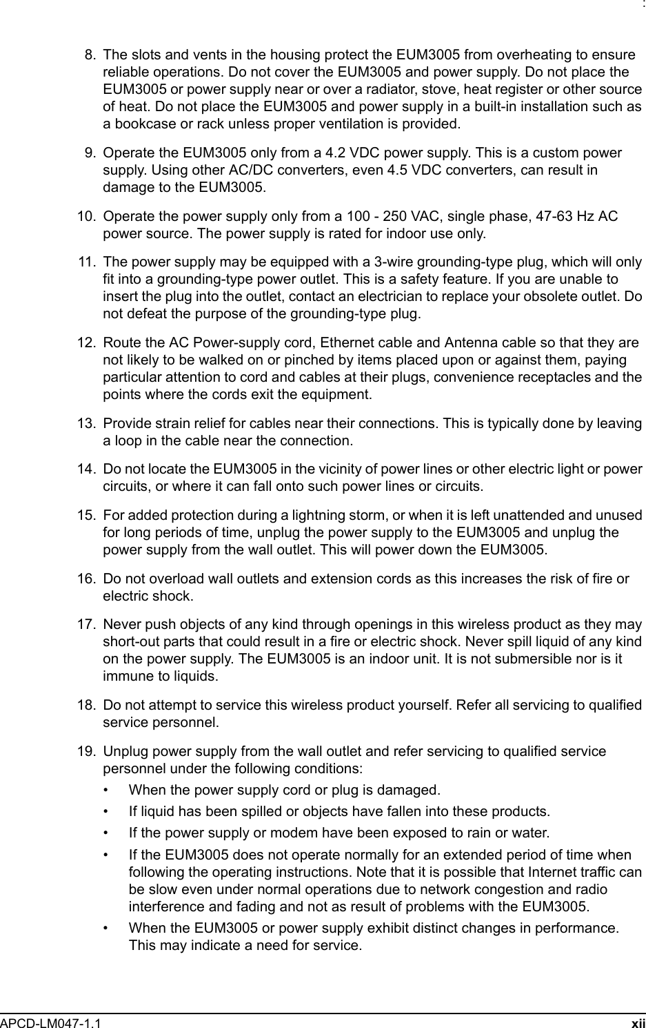
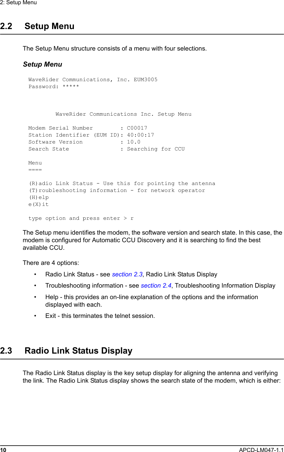
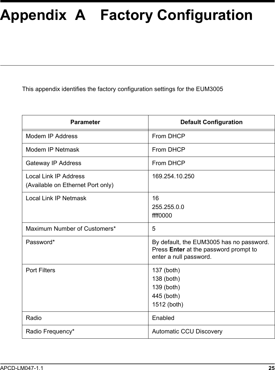
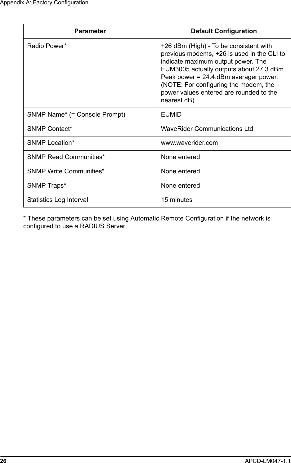
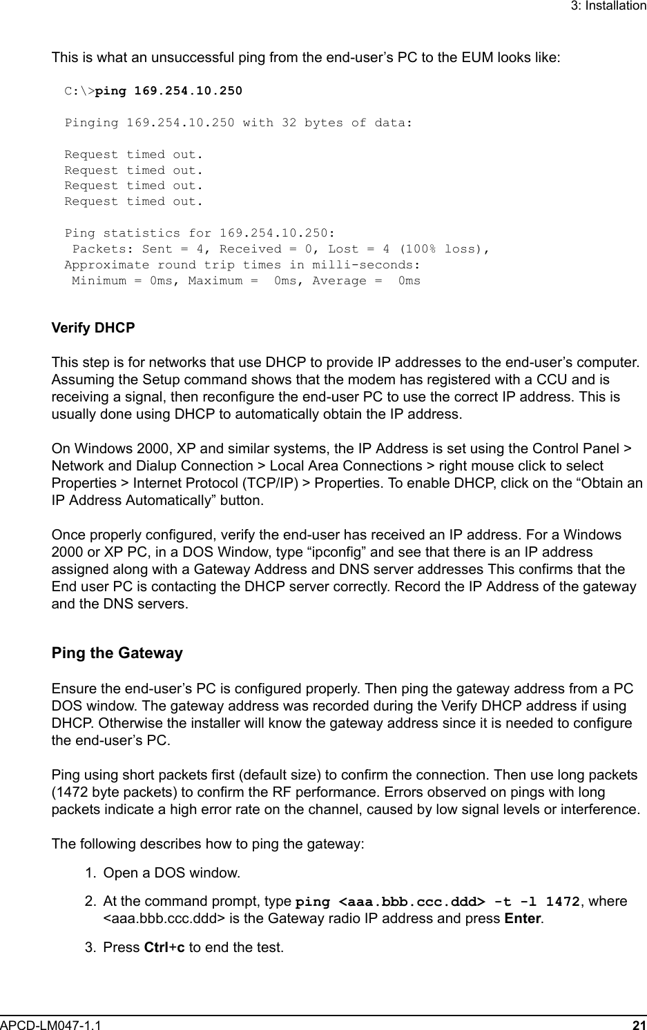
![2: Setup MenuAPCD-LM047-1.1 13with the installation, then the installer may contact the network operator and report the information on this display so that the network operator can troubleshoot the installation.The troubleshooting information display is shown below.Troubleshooting information Display WaveRider Communications Inc. Diagnostic Information----------------- MAC Summary ---------------------------------Transmitted Payloads 1Ok : 35 100.0% 2Ok : 0 0.0% 3Ok : 0 0.0% 4Ok : 0 0.0% Fail Retry : 0 0.0% Fail Timeout : 1Received Packets HCRC Error : 23993 3.0% Directed : 6948 0.8% Broadcast : 11178 1.4% No Match : 753093 94.7%Received Packets with Payloads FCS Error : 0 0.0% Duplicate : 0 0.0% Too Busy - Discard : 0 0.0% Delivered : 73 100.0%-------------------- IP Summary --------------------DHCP Enabled : YESIP Address: 192.168.10.250 / 24IP Subnet : 192.168.10.0 ( 255.255.255.0 )Gateway IP Address: 192.168.10.1------------------- Radio Summary ------------------RF Power: 26 dBmAuto Mode - Locked on frequency 9114 RSSI[dBm] RX; TX; R1; R2; R3; F;Retry%; SQ; RNA; RNBRSSI: -69 1; 0; 0; 0; 0; 0; 0; 8; 31; 29](https://usermanual.wiki/Vecima-Networks/EUM3005/User-Guide-525964-Page-27.png)
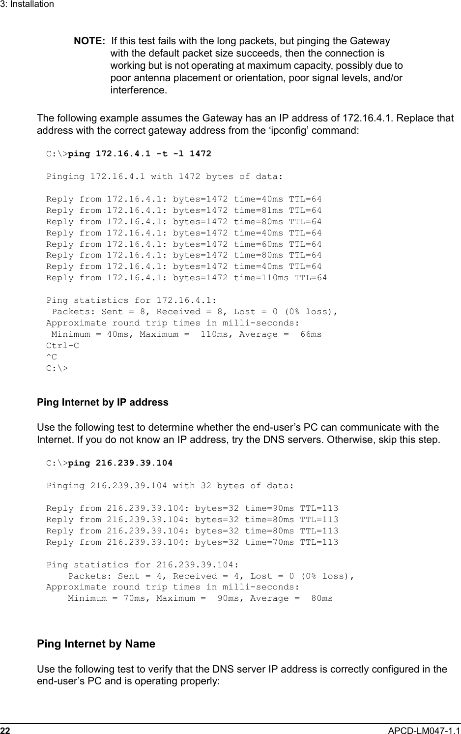
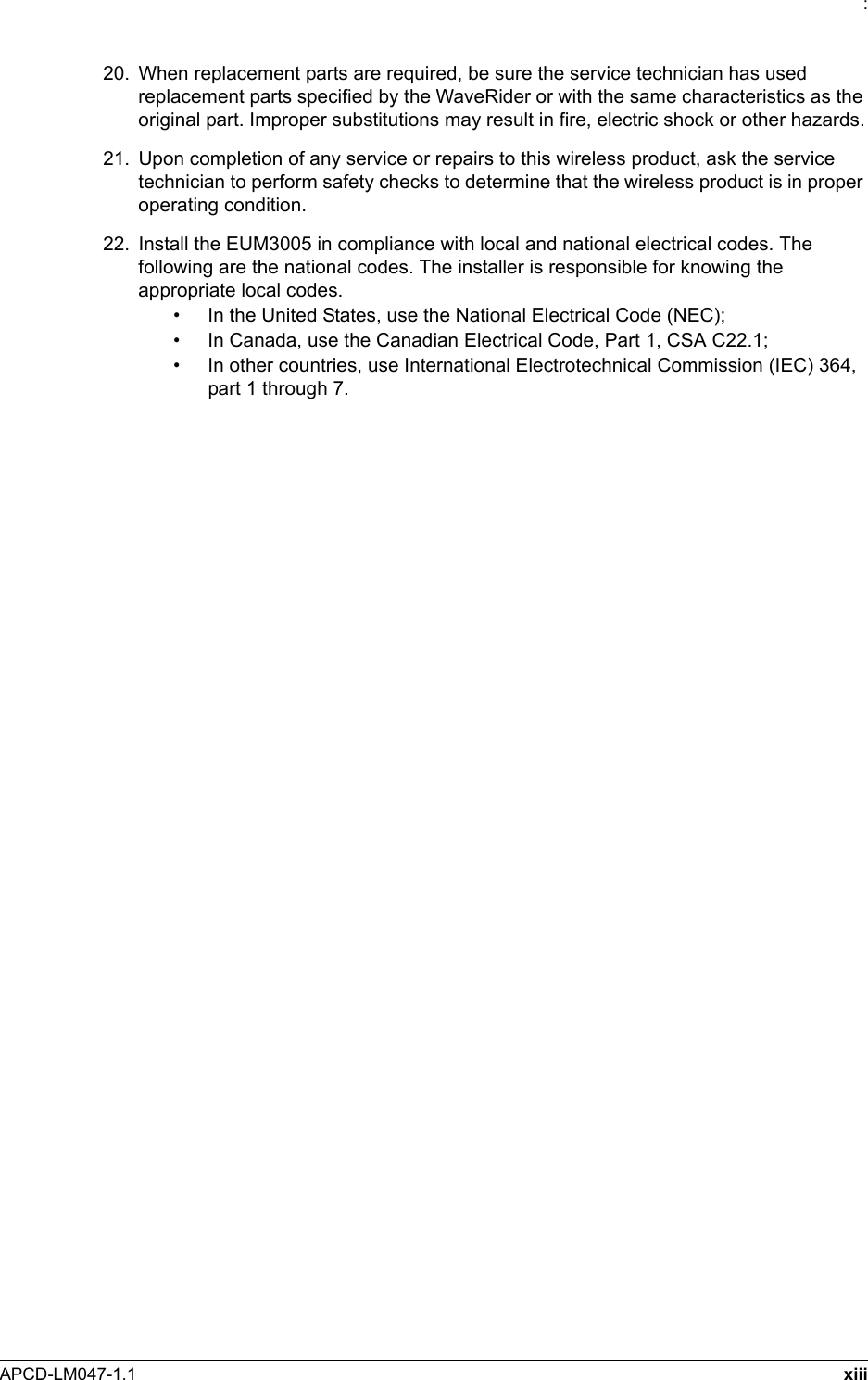
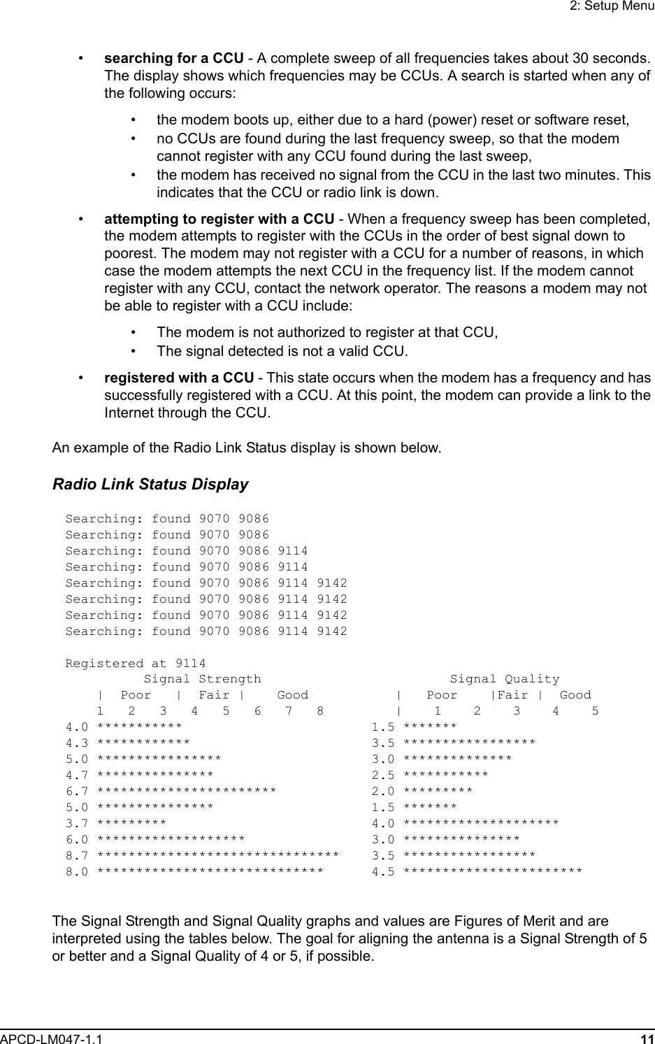
![3: InstallationAPCD-LM047-1.1 23C:\> ping www.google.comPinging www.google.akadns.net [216.239.39.104] with 32 bytes of data:Reply from 216.239.39.104: bytes=32 time=72ms TTL=241Reply from 216.239.39.104: bytes=32 time=69ms TTL=241Reply from 216.239.39.104: bytes=32 time=76ms TTL=241Reply from 216.239.39.104: bytes=32 time=68ms TTL=241Ping statistics for 216.239.39.104: Packets: Sent = 4, Received = 4, Lost = 0 (0% loss),Approximate round trip times in milli-seconds: Minimum = 68ms, Maximum = 76ms, Average = 71ms3.4 Post-InstallationOnce a good link between the CCU and the EUM3005 has been established, the configuration can be completed automatically using the Automatic Remote Configuration feature with a RADIUS Server and database in which the EUM3005 information has been entered. The network operator must update the RADIUS database for the new modem. The configurable items that can be included in the Automatic Remote Configuration include:• password, • all SNMP parameters, • RF Frequency (including enabling Automatic CCU Discovery)• number of customers.If the Automatic Remote Configuration feature is not used, then the network operator can connect to the EUM3005 over the air and complete the configuration.Details on configuring a RADIUS Server or manually configuring an individual EUMs are covered in the LMS4000 Managing the Network manual or other manuals, available on the WaveRider web-site.](https://usermanual.wiki/Vecima-Networks/EUM3005/User-Guide-525964-Page-37.png)