Vecima Networks MA4367 MCS Transmitter / Upconverter System User Manual ma4367 ml 03 sd
Vecima Networks Inc. MCS Transmitter / Upconverter System ma4367 ml 03 sd
UserManual.wiki
>
Vecima Networks
>
MA4367 User Manual
User Manual
Navigation menu
Upload a User Manual
Namespaces
Wiki Guide
HTML
PDF
Info
Views
User Manual
Discussion / Help
Navigation

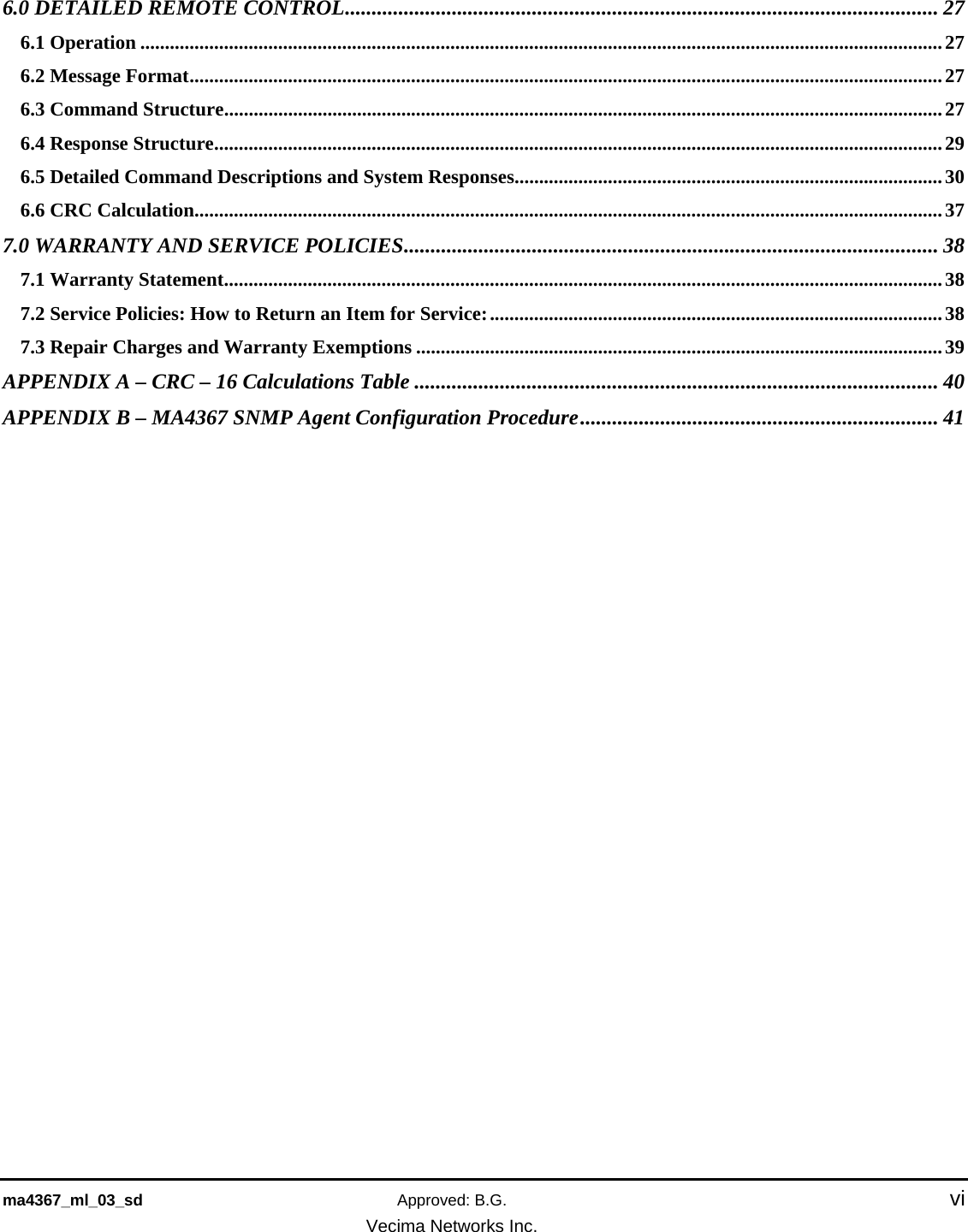
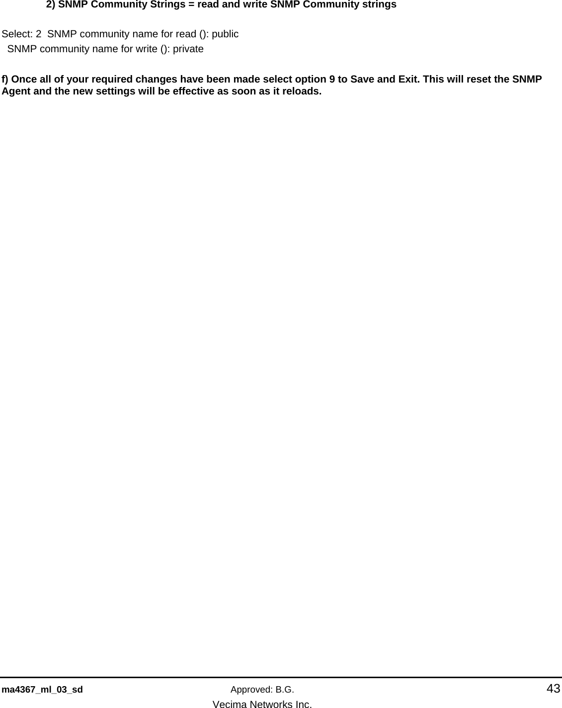
![ma4367_ml_03_sd Approved: B.G. 8 Vecima Networks Inc. 1.5 Specifications IF INPUT IF Center Frequency 44.00 MHz Input Bandwidth 6.0 MHz IF Input Level 25 to 35 dBmV Input Connector F female connector, 75 ohm IF AGC Selectable enable/disable RF OUTPUT Output Frequency Band 2505 to 2681 MHz Linear Output Power [64/256 QAM] +36 dBm for MER >= 38 dB Output level adjustment 0 to -15 dB Spectrum Inverted relative to IF input Output Connector N female connector, 50 ohm Frequency Step Size 62.5 kHz steps, 2505 to 2681 MHz Output Bandwidth 6.0 MHz Frequency Stability (10 to 40°C) ±3 kHz (MA4011B/MA4012B TCXO 1 ppm) Gain Flatness ±0.8 dB over 6 MHz Gain Stability ±0.7 dB (10 to 40°C) Mute Level -60 dBc Phase Noise -94 dBc/Hz at 10 kHz offset POWER CONSUMPTION AC Option 120 VAC nominal (100 to 240 VAC), 50/60 Hz, 175 W max. DC Option -48 VDC nominal (-36 to -60 VDC), 175 W max. MISCELLANEOUS Remote Control Interface RS232/RS485 (SNMP or alarm contact closure optional) Remote Control Connector RJ45 (in and out) Operating Temperature 10 to 40°C (50 to 104°F) Relative Humidity 95% max. Configuration Standard 19" rack mount, 4U height, front panel control/display Dimensions 17.5" (w) x 13.7" (d) x 7" (h) (44.4 x 34.8 x 17.8 cm) COMPONENTS MA4003 MMDS Chassis MA4011B (AC) or MA4012B (DC) power/control modules MA4061B MMDS Upconverter MA4070C MMDS Power Amplifier Specifications subject to change without notice. 1.6 Available MA4367 System Configurations The MA4367 is available in the following configurations: System Description MA4367AC 2.5GHz TX/UC System,100-240VAC MA4367AC/SNMP 2.5GHz TX/UC System,100-240VAC,SNMP MA4367AC/SNMP/EA 2.5GHz TX/UC System,100-240VAC,SNMP,ExternalAlarm MA4367DC 2.5GHz TX/UC System,-48VDC MA4367DC/SNMP 2.5GHz TX/UC System,-48VDC,SNMP MA4367DC/SNMP/EA 2.5GHz TX/UC System,-48VDC,SNMP,ExternalAlarm](https://usermanual.wiki/Vecima-Networks/MA4367/User-Guide-845062-Page-8.png)
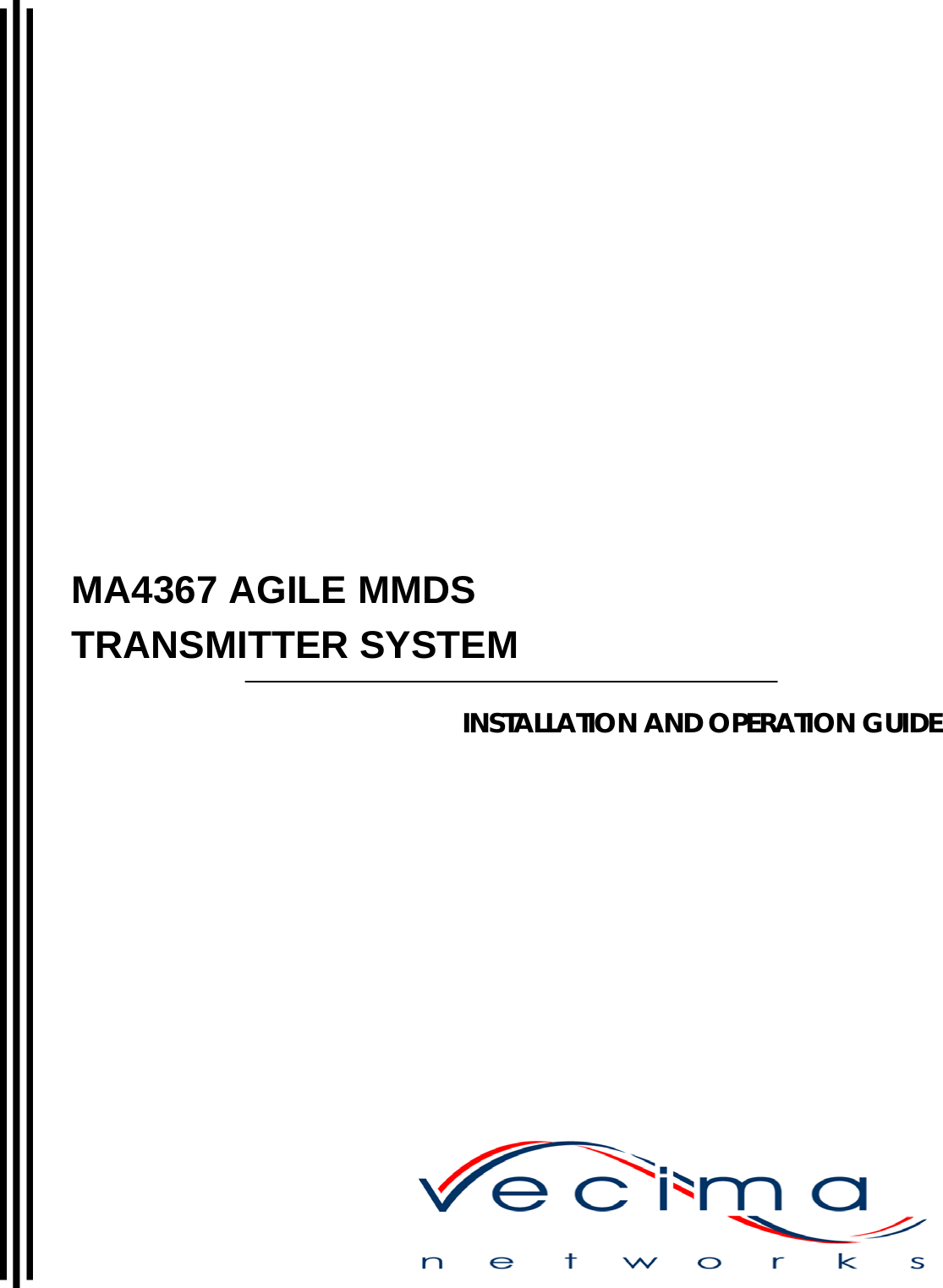
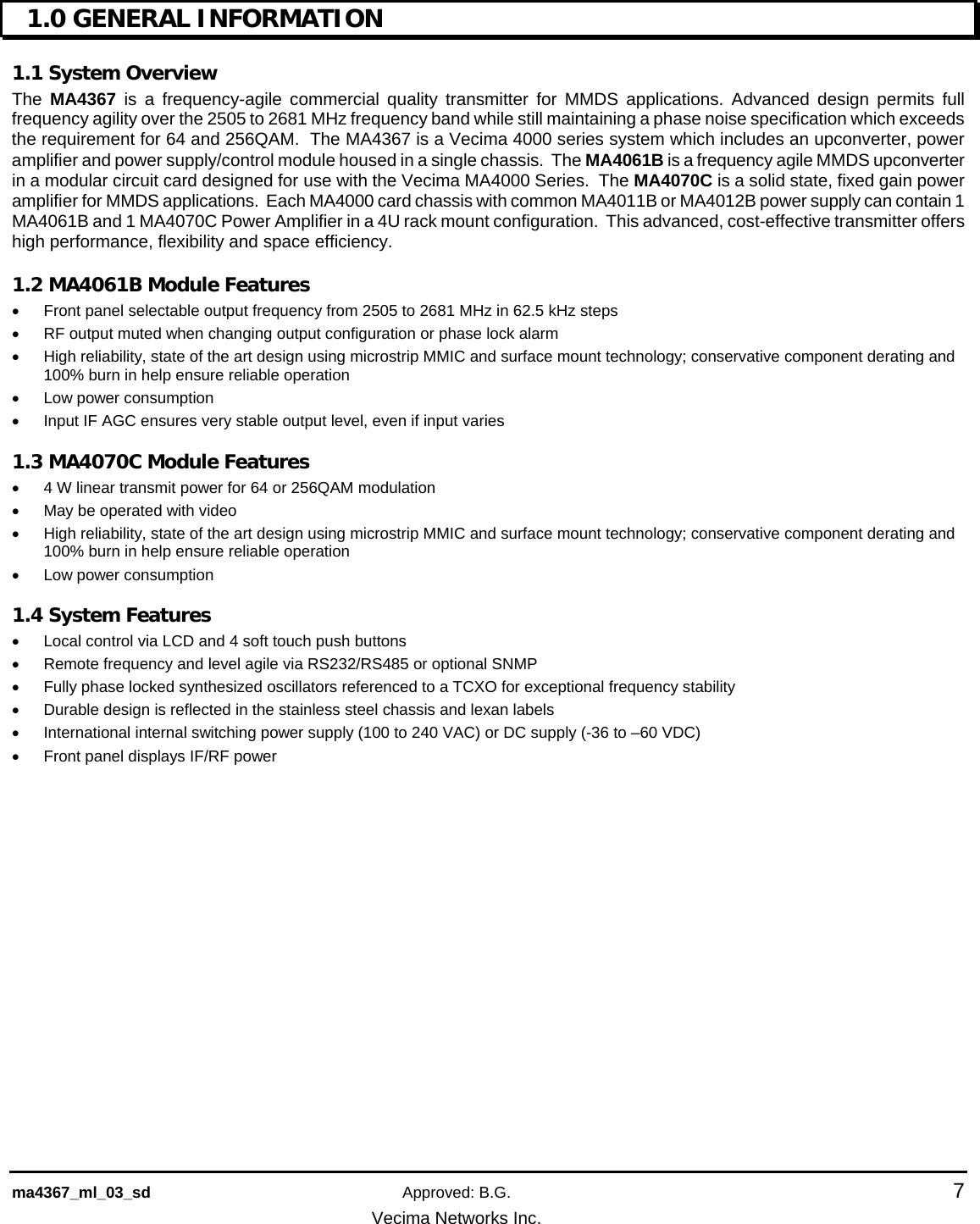
![ma4367_ml_03_sd Approved: B.G. 41 Vecima Networks Inc. APPENDIX B – MA4367 SNMP AGENT CONFIGURATION PROCEDURE The MA4367 SNMP agent is an optional feature that must be factory installed at time of order a) Once PC on same 10.10.10.0 network is connected to the unit with a cross-over Ethernet cable try pinging the unit. This can be done from the DOS prompt. Microsoft Windows XP [Version 5.1.2600] (C) Copyright 1985-2001 Microsoft Corp. C:\>ping 10.10.10.11 Pinging 10.10.10.11 with 32 bytes of data: Reply from 10.10.10.11: bytes=32 time=1ms TTL=64 Reply from 10.10.10.11: bytes=32 time=1ms TTL=64 Reply from 10.10.10.11: bytes=32 time=1ms TTL=64 Reply from 10.10.10.11: bytes=32 time=2ms TTL=64 Ping statistics for 10.10.10.11: Packets: Sent = 4, Received = 4, Lost = 0 (0% loss), Approximate round trip times in milli-seconds: Minimum = 1ms, Maximum = 2ms, Average = 1ms b) In order to be sure that you are indeed connected to the right unit check the arp cache. The MAC/physical address listed for 10.10.10.11 should be the same address listed on the back label of the unit. C:\>arp -a Interface: 10.10.10.2 --- 0x10004 Internet Address Physical Address Type 10.10.10.11 00-20-4a-72-1b-5c dynamic c) In order to access the SNMP Agent configuration menus telnet to 10.10.10.11 9999. C:\>telnet 10.10.10.11 9999 *** Wavecom SNMP Proxy Agent Serial Number 7207004 MAC address 00:20:4A:72:1B:5C Software version V5.20 Press Enter to go into Setup Mode](https://usermanual.wiki/Vecima-Networks/MA4367/User-Guide-845062-Page-41.png)