Vecima Networks MA4367 MCS Transmitter / Upconverter System User Manual ma4367 ml 03 sd
Vecima Networks Inc. MCS Transmitter / Upconverter System ma4367 ml 03 sd
User Manual

MA4367 AGILE MMDS
TRANSMITTER SYSTEM
INSTALLATION AND OPERATION GUIDE

ma4367_ml_03_sd Approved: B.G. ii
Vecima Networks Inc.
Document: ma4367_ml_03_sd
Approved: B.G.
Proprietary to Vecima Networks Inc.
All rights reserved.
No part of this publication may be reproduced in any form or by any means used to make any derivative work (such as translation, transformation or
adaptation) without written permission from Vecima Networks Inc.
Vecima Networks Inc. reserves the right to revise this publication and to make changes in content from time to time without obligation on the part of
Vecima Networks Inc. to provide notification of such revision or change.
Vecima Networks Inc. provides this guide without warranty of any kind, either implied or expressed, including, but not limited to, the implied warranties of
merchantability and fitness for a particular purpose. Vecima Networks Inc. may make improvements or changes in the product(s) described in this
manual at any time.
Specifications subject to change without notice — Printed in Canada

ma4367_ml_03_sd Approved: B.G. iii
Vecima Networks Inc.
Thank you for purchasing this product from Vecima Networks!
Vecima Networks is a leading technology design center and provides
innovative solutions for the ongoing video, voice and data delivery revolution.
Since 1988, our design powerhouse has created custom RF and digital products for technology
leaders such as AT&T, Cisco Systems, Cogeco, Comcast and Cox Communications. All Vecima
Networks products benefit from this ground-breaking expertise.
Vecima Networks designs and manufactures:
z 256 QAM Upconverters z Digital Video Modulators z Agile CATV Modulators
z Frequency Translators z Spread Spectrum Devices z MMDS Transceivers
z Off-air/CATV Demodulators z Wireless Cable MMDS z Wireless Cable LMDS
z Edge Devices z Video On Demand Products and more!
For additional product or corporate information, please contact Vecima Networks at:
Vecima Networks Inc.
150 Cardinal Place
Saskatoon, SK Canada S7L 6H7
Tel: (306) 955-7075
Fax: (306) 955-9919
Web: www.vecimanetworks.com
Email: sales@vecimanetworks.com

ma4367_ml_03_sd Approved: B.G. iv
Vecima Networks Inc.
SAFETY PRECAUTIONS
1. Before installing and operating this equipment, read all Safety, Installation and Operating sections. Retain this manual
for future reference.
2. Follow all instructions — Failure to do so may result in damage to the unit or severe personal injury.
3. The user should not attempt servicing. There are no user serviceable parts inside. Refer all servicing to factory
qualified personnel.
4. Shock Hazard — An electrical shock hazard exists when the chassis cover is removed as is required to set internal
controls. Always disconnect power from the unit before removing the cover.
5. Cleaning — Do not use liquid or aerosol cleaners. Use a damp cloth for cleaning.
Warning Do not work on the system or connect or disconnect cables during periods of lightning activity.
LES PRÉCAUTIONS DE SÉCURITÉ
1. Avant d'installer ou d'opérer cet équipement, lisez, toutes les sections de sécurités, d'installations et d'opérations.
Gardez ce manuel comme source de référence.
2. Suivez toutes instructions - si non, vous risquez d'endommager la machine ou de vous blesser sérieusement.
3. N'essayez pas de réparer cet équipement vous même. Référez toutes revisions nécessaire au personnel qualifié de
la manufacture.
4. Risque de choc - Il y a un risque de décharge électrique qui existe quand la couverture du châssis est enlevée,
comme est nécessaire pour ajuster les contrôls internes. Il faut toujours couper l'électricité avant d'enlever le
couvercle pour faire aucun ajustage.
5. Le nettoyage - n'utilisez pas de nettoyeurs aérosols ou liquides. Utilisez un tissu humide pour nettoyer.
Attention Ne pas travailler sur le système ni brancher ou débrancher les câbles pendant un orage du foudre.

ma4367_ml_03_sd Approved: B.G. v
Vecima Networks Inc.
INDEX
1.0 GENERAL INFORMATION.......................................................................................................................... 7
1.1 System Overview .........................................................................................................................................................7
1.2 MA4061B Module Features........................................................................................................................................7
1.3 MA4070C Module Features .......................................................................................................................................7
1.4 System Features...........................................................................................................................................................7
1.5 Specifications ...............................................................................................................................................................8
1.6 Available MA4367 System Configurations ...............................................................................................................8
2.0 INSTALLATION ............................................................................................................................................. 9
2.1 Unpacking the Unit .....................................................................................................................................................9
2.2 Operating Environment..............................................................................................................................................9
2.3 Power Requirements.................................................................................................................................................10
2.4 Rack Mounting..........................................................................................................................................................10
2.5 Module Installation/Replacement............................................................................................................................10
3.0 OPERATION ................................................................................................................................................. 11
3.1 Front Panel Description............................................................................................................................................11
3.2 Front Panel Operating Modes..................................................................................................................................15
3.3 Remote Control Operating Instructions .................................................................................................................19
4.0 REAR PANEL CONNECTIONS .................................................................................................................. 20
4.1 MA4011B – AC Power/Control Module..................................................................................................................20
4.1 MA4012B – DC Power/Control Module..................................................................................................................20
4.2 MA4061B - MMDS Upconverter Card ...................................................................................................................23
4.3 MA4070C - Power Amplifier....................................................................................................................................23
5.0 STATUS AND ERROR CODES ................................................................................................................... 24
5.1 MA4061B Status and Error Codes..........................................................................................................................24
5.2 MA4070C Status and error Codes...........................................................................................................................25
5.3 MA4011B Power/Control Module Status and Error Codes..................................................................................26

ma4367_ml_03_sd Approved: B.G. vi
Vecima Networks Inc.
6.0 DETAILED REMOTE CONTROL............................................................................................................... 27
6.1 Operation ...................................................................................................................................................................27
6.2 Message Format.........................................................................................................................................................27
6.3 Command Structure..................................................................................................................................................27
6.4 Response Structure....................................................................................................................................................29
6.5 Detailed Command Descriptions and System Responses.......................................................................................30
6.6 CRC Calculation........................................................................................................................................................37
7.0 WARRANTY AND SERVICE POLICIES.................................................................................................... 38
7.1 Warranty Statement..................................................................................................................................................38
7.2 Service Policies: How to Return an Item for Service:............................................................................................38
7.3 Repair Charges and Warranty Exemptions ...........................................................................................................39
APPENDIX A – CRC – 16 Calculations Table .................................................................................................. 40
APPENDIX B – MA4367 SNMP Agent Configuration Procedure................................................................... 41

ma4367_ml_03_sd Approved: B.G. 7
Vecima Networks Inc.
1.0 GENERAL INFORMATION
1.1 System Overview
The MA4367 is a frequency-agile commercial quality transmitter for MMDS applications. Advanced design permits full
frequency agility over the 2505 to 2681 MHz frequency band while still maintaining a phase noise specification which exceeds
the requirement for 64 and 256QAM. The MA4367 is a Vecima 4000 series system which includes an upconverter, power
amplifier and power supply/control module housed in a single chassis. The MA4061B is a frequency agile MMDS upconverter
in a modular circuit card designed for use with the Vecima MA4000 Series. The MA4070C is a solid state, fixed gain power
amplifier for MMDS applications. Each MA4000 card chassis with common MA4011B or MA4012B power supply can contain 1
MA4061B and 1 MA4070C Power Amplifier in a 4U rack mount configuration. This advanced, cost-effective transmitter offers
high performance, flexibility and space efficiency.
1.2 MA4061B Module Features
• Front panel selectable output frequency from 2505 to 2681 MHz in 62.5 kHz steps
• RF output muted when changing output configuration or phase lock alarm
• High reliability, state of the art design using microstrip MMIC and surface mount technology; conservative component derating and
100% burn in help ensure reliable operation
• Low power consumption
• Input IF AGC ensures very stable output level, even if input varies
1.3 MA4070C Module Features
• 4 W linear transmit power for 64 or 256QAM modulation
• May be operated with video
• High reliability, state of the art design using microstrip MMIC and surface mount technology; conservative component derating and
100% burn in help ensure reliable operation
• Low power consumption
1.4 System Features
• Local control via LCD and 4 soft touch push buttons
• Remote frequency and level agile via RS232/RS485 or optional SNMP
• Fully phase locked synthesized oscillators referenced to a TCXO for exceptional frequency stability
• Durable design is reflected in the stainless steel chassis and lexan labels
• International internal switching power supply (100 to 240 VAC) or DC supply (-36 to –60 VDC)
• Front panel displays IF/RF power

ma4367_ml_03_sd Approved: B.G. 8
Vecima Networks Inc.
1.5 Specifications
IF INPUT
IF Center Frequency 44.00 MHz
Input Bandwidth 6.0 MHz
IF Input Level 25 to 35 dBmV
Input Connector F female connector, 75 ohm
IF AGC Selectable enable/disable
RF OUTPUT
Output Frequency Band 2505 to 2681 MHz
Linear Output Power [64/256 QAM] +36 dBm for MER >= 38 dB
Output level adjustment 0 to -15 dB
Spectrum Inverted relative to IF input
Output Connector N female connector, 50 ohm
Frequency Step Size 62.5 kHz steps, 2505 to 2681 MHz
Output Bandwidth 6.0 MHz
Frequency Stability (10 to 40°C) ±3 kHz (MA4011B/MA4012B TCXO 1 ppm)
Gain Flatness ±0.8 dB over 6 MHz
Gain Stability ±0.7 dB (10 to 40°C)
Mute Level -60 dBc
Phase Noise -94 dBc/Hz at 10 kHz offset
POWER CONSUMPTION
AC Option 120 VAC nominal (100 to 240 VAC), 50/60 Hz, 175 W max.
DC Option -48 VDC nominal (-36 to -60 VDC), 175 W max.
MISCELLANEOUS
Remote Control Interface RS232/RS485 (SNMP or alarm contact closure optional)
Remote Control Connector RJ45 (in and out)
Operating Temperature 10 to 40°C (50 to 104°F)
Relative Humidity 95% max.
Configuration Standard 19" rack mount, 4U height, front panel control/display
Dimensions 17.5" (w) x 13.7" (d) x 7" (h) (44.4 x 34.8 x 17.8 cm)
COMPONENTS
MA4003 MMDS Chassis
MA4011B (AC) or MA4012B (DC) power/control modules
MA4061B MMDS Upconverter
MA4070C MMDS Power Amplifier
Specifications subject to change without notice.
1.6 Available MA4367 System Configurations
The MA4367 is available in the following configurations:
System Description
MA4367AC 2.5GHz TX/UC System,100-240VAC
MA4367AC/SNMP 2.5GHz TX/UC System,100-240VAC,SNMP
MA4367AC/SNMP/EA 2.5GHz TX/UC System,100-240VAC,SNMP,ExternalAlarm
MA4367DC 2.5GHz TX/UC System,-48VDC
MA4367DC/SNMP 2.5GHz TX/UC System,-48VDC,SNMP
MA4367DC/SNMP/EA 2.5GHz TX/UC System,-48VDC,SNMP,ExternalAlarm

ma4367_ml_03_sd Approved: B.G. 9
Vecima Networks Inc.
2.0 INSTALLATION
CAUTION: This device must be professionally installed.
1 mW/CM2 is the maximum permissible exposure for radio transmitters between 1.5 to 100 GHz for uncontrolled environments.
The installer of this radio equipment must ensure that the antenna is located or pointed such that it does not emit RF fields in
excess of the FCC recommended limits.
For more information, refer to the Federal Communications Commission guidelines on radio frequency safety, accessible
through their Web site: www.fcc.gov.
2.1 Unpacking the Unit
Carefully remove the equipment from its packing material and set it on a solid surface, such as a table or desk. If it appears
damaged in any way, notify the carrier, and keep all packing materials for inspection by the carrier’s agent.
2.2 Operating Environment
The MA4367 system includes an active cooling fan tray which forces cooling air from the bottom through to the top of the
chassis. For adequate ventilation, a space of 1U (1.75”) should be left in the rack, directly above the MA4367 chassis for warm
air exhaust. It is designed to operate at temperatures ranging from 10 to 40oC (50 to 104oF). As with all electrical equipment,
operation at excessive temperature accelerates the deterioration of components. For this reason, measures should be taken to
prevent the build up of excessive heat in the rack.
Antenna Requirements
The MA4367 is operated with a user-supplied antenna. Please consult table 2.2A for further information. Mount the antenna
according to the manufacturer’s instructions.
TABLE 2.2A: ANTENNA LIST
Transmitter Power Antenna Type Antenna Gain Safe Distance
(Watts) (dBm) (dBi) (meters)
4 36.0 Omni 10 0.59
4 36.0
180° Sectoral 9.5 0.56
4 36.0
180° Sectoral 12.5 0.79
4 36.0
120° Sectoral 11 0.66
4 36.0
120° Sectoral 14 0.93
4 36.0
90° Sectoral 13 0.83
4 36.0
90° Sectoral 16 1.18
( Caution: The antenna(s) used for MA4367 Agile MMDS Transmitter system is to be installed in an
outdoor fixed environment. The antenna is to be mounted on an outdoor permanent structure with a
minimum separation distance of 1.5 meters between the antenna elements and nearby persons.
RF exposure compliance is addressed at the time of licensing.
( The maximum recommended antenna gain is 18 dBi.

ma4367_ml_03_sd Approved: B.G. 10
Vecima Networks Inc.
2.3 Power Requirements
The equipment is supplied with either an AC international auto-ranging internal power supply which allows it to be powered
from any 100 to 240 VAC; 50 to 60 Hz source, or a DC supply capable of operating from –36 to –60 VDC.
Check the total current consumption of all equipment on the same line before applying power to the MA4367 system.
Avoid sharing a power source that feeds heavy motors or other equipment, which require large current drains.
2.4 Rack Mounting
The MA4367 system is designed for standard rack mounting in a 19” equipment rack. It requires 4U (7.00”) of vertical rack
space. It should be installed in a rack allowing access to the back of the unit. The upconverter should be isolated from
strong RF radiation emanating from local equipment in the rack. Power line transients that may cause damage to the unit
should be avoided. For adequate ventilation, a space of 1U (1.75”) should be left in the rack, directly above the MA4367
chassis for warm air exhaust.
2.5 Module Installation/Replacement
1. Power off the chassis using the rear panel power switch
2. Disconnect the RF cables from the rear of the corresponding module
3. Using a screwdriver, loosen the corresponding front panel captive screws until the module is free to pull forward
4. Insert the replacement module and retighten the front panel captive screws
5. Turn on the power switch
6. Configure the output frequency and IF/RF levels. Note that after power cycle, the frequency of the MA4061B needs to be re-entered
in order for the power detectors on the MA4070C to lock on properly.
7. Reconnect the rear panel RF cables
ma4367_ml_03_sd Approved: B.G. 11
Vecima Networks Inc.
3.0 OPERATION
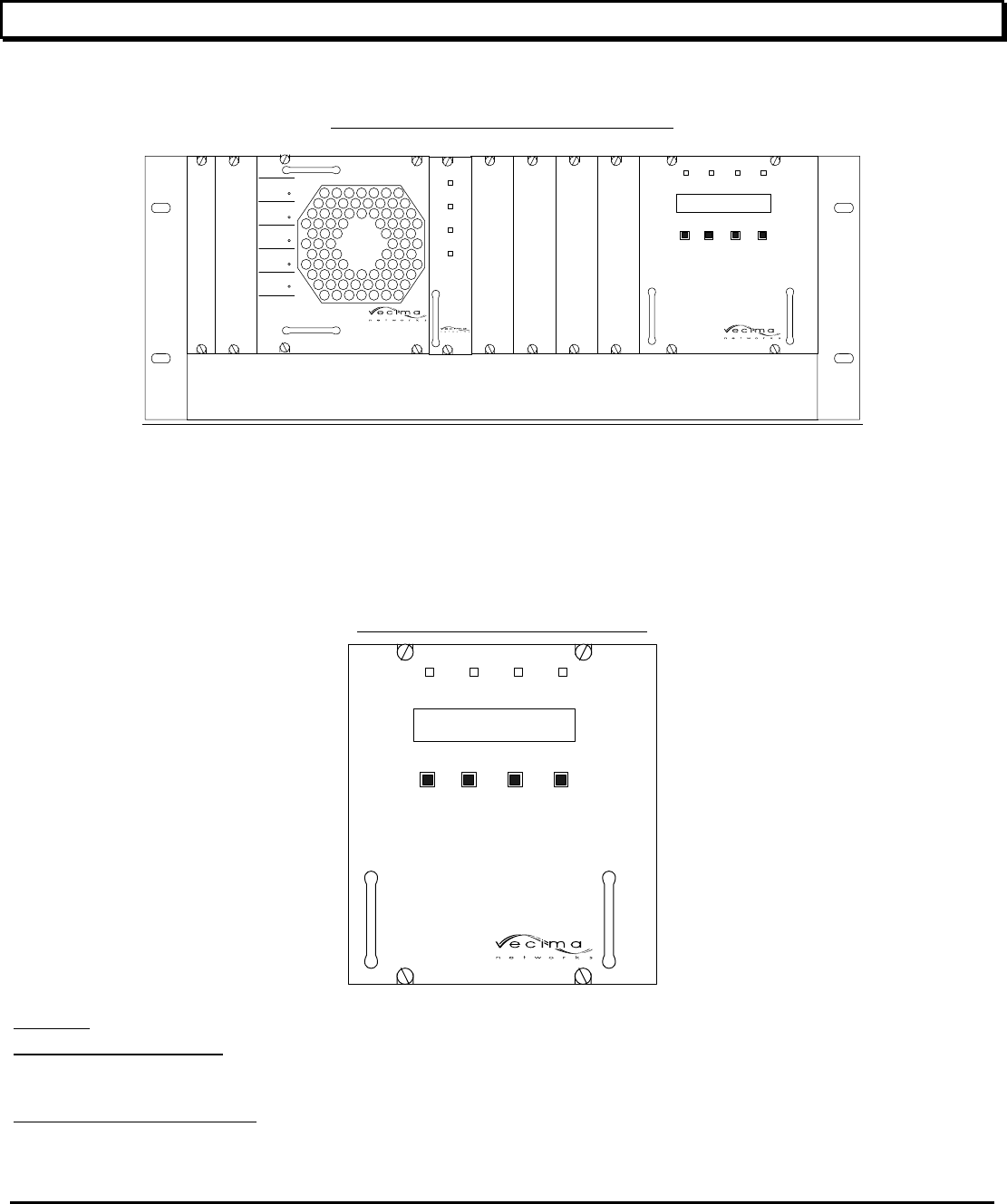
3.1 Front Panel Description
DIAGRAM 3.1A : FRONT PANEL – MA4367 SYSTEM
Vecima Networ ks
MA4009B
POWER ALARM MODULE
SELECT AUX
SYSTEM 4000
POWER SUPPLY
MA4011B
DOWN UP MODE MODULE
SELECT
Vecima Networ ks
MA4009B
Vecima Networks
MA4009B
Vecima Networks
MA4009B
Vecima Networks
MA4009B
MA4070C MMDS
POWER AMPLIFIER
2.5-2.7 GHz
DC
POWER
RF HIGH
ALARM
RF LOW
ALARM
HIGH REV.
POWER
ALARM
UNIT
SELECT
POWER
MODULE
SELECT
ALARM
RF ENABLED
MA4061B
MMDS DIGITAL
UPCONVERTER
As shown in Diagram 3.1A, the power/control module front panel has an LCD display, four soft touch push buttons, and 4
indicator LEDs. All other modules have 4 indicator LEDs. Modules are configured using push buttons on the power supply
module, or via the remote interface. If no configuration adjustments are being made via the front panel controls, the display
back light will shut off after a five minute interval. Pressing any of the front panel buttons will re-enable the back light.
3.1.1 MA4011B/MA4012B Power/Control Modules
DIAGRAM 3.1B : FRONT PANEL – MA4367
POWER ALARM MODULE
SELECT AUX
SYSTEM 4000
POWER SUPPLY
MA4011B
DOWN UP MODE MODULE
SELECT
DISPLAY
The first line on the display is the Mode Information Line. It shows the settings for the currently selected module. The possible
operating modes depend upon the currently selected module (See Section 3.2, Front Panel Operating Modes for a detailed
description of the available modes).
The second line on the display is the Status Information Line. The Status Line is divided as follows:
The two leftmost characters are “mX” where X is replaced by the currently selected module address. When used with the
MA4070C Power Amp Module or the MA4070C Power Amp Module, they can be installed as shown in Diagram 3.1A.

ma4367_ml_03_sd Approved: B.G. 12
Vecima Networks Inc.
( Each MA4003 chassis can accommodate one MA4061B Upconverter Module and one MA4070C Power Amplifier
Module.
The next two characters are “sXX” where “XX” indicate the status code for the currently selected module. Refer to Section
5.0, Status Codes for a list of current status codes.
The next two characters are “eXX” where “XX” indicates the error code for the currently selected module. (This code is only
displayed when it is non-zero). Refer to Section 6.0, Error Codes for the list of current error codes.
The final three characters indicate if local front panel control of the MA4003 chassis is enabled. Local/Remote control is
indicated by “L/R” while remote-only control is indicated by “R”. With remote-only control, the local control via the front
panel is locked out.
MODULE SELECT BUTTON
The MODULE SELECT button allows the user to select the module to display and/or control (the MODULE SELECT LED
will be lit on the selected module, and the LCD display will indicate the module address in the status line).
MODE BUTTON
The MODE button allows the user to cycle through each of the various modes for the selected module.
UP/DOWN BUTTONS
The UP/DOWN buttons adjust the settings for the currently selected mode of the selected module.
POWER ON LED
When the green POWER ON indicator is illuminated, the module has been correctly installed and powered on.
ALARM LED
A constant Alarm LED on the MA4011B/MA4012B indicates a critical alarm condition. Detailed alarm information is
available by selecting the module from the front panel and observing the status and error codes on the LCD display.
MODULE SELECT LED
When the green MODULE SELECT indicator is illuminated, it indicates that the corresponding module has been selected
from the front panel or via the remote control interface.
AUX LED
This LED is reserved for future use.
ma4367_ml_03_sd Approved: B.G. 13
Vecima Networks Inc.
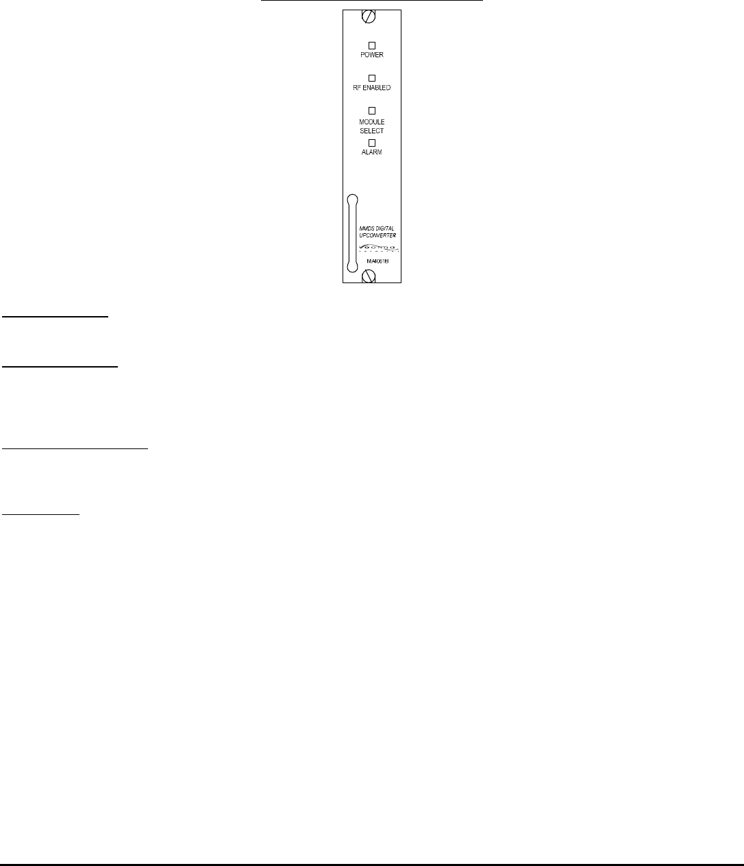
3.1.2 MA4061B – Upconverter Card
DIAGRAM 3.1C : FRONT PANEL – MA4367
POWER ON LED
When the green POWER ON indicator is illuminated, the module has been correctly installed and powered on.
RF ENABLED LED
When the green RF ENABLED indicator is illuminated, the internal output circuitry is enabled to provide an RF output. The
RF ENABLED indicator does not necessarily indicate the presence of an output, it only reflects that the module is capable
of an RF output if an IF input is applied and the levels configured.
MODULE SELECT LED
When the green MODULE SELECT indicator is illuminated, it indicates that the corresponding module has been selected
from the front panel or via the remote control interface.
ALARM LED
The red MA4061B ALARM indicator has two modes. A flashing Alarm LED indicates a non-critical alarm condition (i.e. soft
alarm). A constant Alarm LED indicates a critical alarm condition (i.e. hard alarm). Detailed alarm information is available
by selecting the corresponding module from the front panel and observing the status and error codes on the LCD display.
ma4367_ml_03_sd Approved: B.G. 14
Vecima Networks Inc.
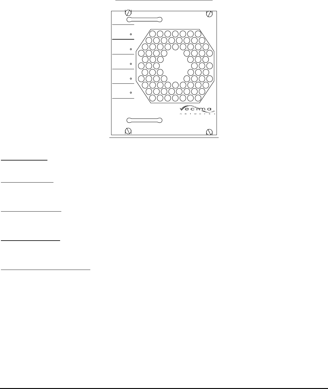
3.1.3 MA4070C – Power Amplifier
DIAGRAM 3.1D : FRONT PANEL – MA4367
MA4070C MMDS
POWER AMPLIFIER
2.5-2.7 GHz
DC
POWER
RF HIGH
ALARM
RF LOW
ALARM
HIGH REV.
POWER
ALARM
UNIT
SELECT
DC POWER LED
When the green DC POWER indicator is illuminated, the module has been correctly installed and powered on.
UNIT SELECT LED
When the green UNIT SELECT indicator is illuminated, the corresponding module has been selected from the front panel
or via the remote control interface.
RF HIGH ALARM LED
When the RF HIGH ALARM LED is illuminated, detected power levels have exceeded acceptable limits. Limits will
depend on whether default or custom thresholds are set.
RF LOW ALARM LED
When the RF LOW ALARM LED is illuminated, detected power levels have fallen below acceptable limits. Limits will
depend on whether default or custom thresholds are set.
HIGH REV POWER ALARM LED
When the HIGH REV POWER ALARM LED is illuminated, detected power levels have exceeded acceptable limits. Limits
will depend on whether default or custom thresholds are set.

ma4367_ml_03_sd Approved: B.G. 15
Vecima Networks Inc.
3.2 Front Panel Operating Modes
3.2.1 MA4061B Upconverter Modes
FREQUENCY
When this mode is selected, the display will read: Frq XXXX.XXXX MHz
The displayed frequency is the current configured Output Frequency. To adjust the output frequency, use the UP/DOWN
buttons. Single stepping will allow 62.5 kHz adjustment, while holding the buttons depressed will change the frequency more
quickly.
( The displayed frequency represents the center of the band.
( During frequency change, the output is muted and the RF ENABLED indicator is turned off for 5 seconds to avoid
undesirable interference.
AUTO IF
When this mode is selected, the display will read: IF AGC Enabled
or
IF AGC Disabled
Pressing the Up or Down buttons will toggle the display between Enabled and Disabled. When enabled, the MA4061B will
automatically optimize the IF level and ensure it is within a pre-set threshold range (default ±0.5 dB). When disabled, the IF
level can be manually adjusted as described in the next section.
( The Auto IF mode should only be used for continuous IF inputs (non-bursty).
( If the IF level is not within ±4.0 dB of the optimum level during Auto IF mode, the output will be muted to avoid
undesirable interference, and the Alarm LED will be on.
( At the time of shipping, the AUTO IF is enabled.
IF LEVEL ADJUST
When this mode is selected, the display will read: IFPwr ±XX.X dB
The display indicates the approximate IF power level measured at the internal IF power detector. To adjust the IF level, use the
UP/DOWN buttons. To configure the MA4061B Upconverter for optimum performance, the IF level should be adjusted to read
approximately 0.0 dB (-0.5 to +0.5). An IF level less than 0 dB will degrade noise performance and a level above 0 dB will
promote intermodulation products.
( The IF level can only be adjusted if the Auto IF mode is disabled.
RF OUTPUT LEVEL ADJUST
When this mode is selected, the display will read: RFPwr ±XX.X dBm
The display indicates the approximate RF output power level measured by the internal RF power detector at the output of the
MA4061B upconverter. To adjust the RF level, use the UP/DOWN buttons. The RF output level may be set within the range of -
15 dBm to +3 dBm.
( Ensure that the IF level is correctly set before adjusting the RF level.
( Adjustments of the MA4061B output level will also directly affect the output level of the MA4070C power amplifier.

ma4367_ml_03_sd Approved: B.G. 16
Vecima Networks Inc.
OUTPUT ENABLE/DISABLE
When this mode is selected, the display will read: Output Enabled
or
Output Disabled
Pressing the Up or Down buttons will toggle the display between Enabled and Disabled. When enabled, the RF output from the
MA4061B Upconverter is enabled. When disabled, the RF output from the MA4061B Upconverter is disabled.
( An RF output is only present when there is a valid IF input configured as described in the previous sections.
This means that at the time of shipping, the output is disabled until a valid input is applied.
IF AND RF ALARM THRESHOLD SETTING
The IF and RF alarm threshold can be configured by the user via remote control.
Default settings are as follows: IF +4, -4 dB, alarm function enabled
RF -15, +4 dBm, alarm function enabled
The IF and RF alarms can be independently enabled or disabled via remote control. Refer to Section 6.5, Detailed Command
Descriptions and System Responses for instructions on how to adjust these settings.
DEFAULT SETTINGS
At the time of shipping from factory, the default settings of the MA4061B are:
AUTO IF AGC enabled
IF & RF Thresholds enabled
Output is disabled (until a vaild input is supplied)
The default status code at the time of shipping is s0E. Once a valid input is applied, this status will change.
3.2.2 MA4070C Power Amplifier Modes
FORWARD POWER
When this mode is selected, the display will read: Fwd Pwr XX.X dB
The display indicates the approximate RF power at the output of the MA4070C power amplifier. To adjust the RF level, use the
UP/DOWN buttons. Note that since the MA4070C is a fixed gain device, the MA4367 transmitter actually adjusts the RF output
power of the MA4061B upconverter. Therefore any changes made to the MA4070C output level will also be reflected in the
MA4061B output level. The RF level is measured by the internal RF power detector at the output of the MA4367 power
amplifier. The detector measures from +20 dBm to +40 dBm. It is recommended to use a calibrated external power meter for
accurate setting of the power level.
( If operating by remote control, adjustments of the forward power level cannot be made directly. The power
must be adjusted by altering the MA4061B output level.
REVERSE POWER
When this mode is selected, the display will read: Rev Pwr XX.X dBm
The display indicates the approximate RF power level returned to the card from mismatched connections, etc. The detector measures from
+20dBm to +40dBm

ma4367_ml_03_sd Approved: B.G. 17
Vecima Networks Inc.
OUTPUT ENABLE/DISABLE
When this mode is selected, the display will read: Output Enabled
or
Output Disabled
Pressing the Up or Down buttons will toggle the display between Enabled and Disabled. When enabled, the RF output from the MA4070C
Power Amplifier is enabled. When disabled, the RF output from the MA4070C Power Amplifier is disabled.
TEMP
When this mode is selected, the screen indicates the internal temperature of the amplifier.
FORWARD AND REVERSE ALARM THRESHOLD SETTING
The IF and RF alarm threshold can be configured by the user via remote control.
Default settings are as follows: ForwardHigh +41 dB, alarm function disabled
ForwardLow +20 dB, alarm function disabled
ReverseHigh +40 dBm, alarm function disabled
The alarms can be independently enabled or disabled via remote control. Refer to Section 6.5, Detailed Command
Descriptions and System Responses for instructions on how to adjust these settings.

ma4367_ml_03_sd Approved: B.G. 18
Vecima Networks Inc.
3.2.3 MA4011B/MA4012B Power/Control Module Modes
ADDRESS
When this mode is selected, the display will read:
Address XXX
( The displayed address is the currently selected MA4003 chassis Address. A different address can be
selected by pressing the Up or Down buttons. The MA4003 chassis has an address from 001 - 999.
The address is only used for remote control and monitoring purposes. The factory default address is
999.
INTERFACE SELECT
When this mode is selected, the display will read: RS232 Selected
or
Comm Disabled
or
SNMP Selected
or
SNMPext Selected
or
Terminl Selected
or
RS485 Selected
Pressing the Up or Down buttons will toggle the display between the above modes.
( The Remote Interface Connector Pinout will change depending upon the Interface Type selected.
Please refer to Section 4.1, Power/Control Module Rear Panel Connection for details.
RS232 SELECTED
In this mode, the external interface is RS232. The interface connector is the lower RJ-45 socket on the rear panel of the power
supply. The display will indicate R/L in the lower right-hand corner. See Section 4.1 for electrical interface details and section 6
for remote control details.
COMM DISABLED
In this mode, remote communications is disabled. The display will still indicate R/L in the corner.
SNMP SELECTED
In this mode, the SNMP communications is enabled. Choosing this mode will set the unit to remote control only, as indicated
by "R" in the corner of the display. In this mode, local control of the unit via the front panel buttons is disabled. See below for
instructions on exiting this mode from the front panel to re-enable local control.
SNMPEXT SELECTED
In this mode, the SNMP communications is enabled using an external SNMP module. This mode in not used unless an
external SNMP module is delivered with the unit. Choosing this mode will set the unit to remote control only, as indicated by
"R" in the corner of the display. In this mode, local control of the unit via the front panel buttons is disabled. See below for
instructions on exiting this mode from the front panel to re-enable local control.
SNMP Breakout Feature

ma4367_ml_03_sd Approved: B.G. 19
Vecima Networks Inc.
This SNMP breakout feature has been added in order to provide the function of exiting from the SNMP control via the front
panel. When the MA4012B power supply indicates SNMP SELECTED or SNMPext SELECTED, the modules in the chassis
will be periodically polled and "R" is displayed in the corner of the display to indicate only remote control is allowed.
SNMP Breakout Procedure
To break out of SNMP control:
1. Press and hold the Module Select button for approximately 10 seconds.
2. Upon release of the Module Select button, all communication to the controller, including SNMP, is
disabled and COMM DISABLED is displayed on the front panel.
Re- enabling SNMP
When the SNMP Controller is in the COMM DISABLED state:
1. Select SNMP ENABLED or “SNMPext ENABLED from the communication type menu.
2. After 5 seconds, the front panel will automatically be locked out.
NOTE: The SNMP module will begin or continue polling if SNMP has been previously enabled through the
MIB browser. There may be some delay, as long as 6 1/2 minutes, before a full chassis scan is performed.
TERMINAL SELECTED
In this mode, the RS232 interface is enabled, with operation suitable for connection to a terminal or terminal emulator. The
remote protocol is similar to the normal RS232 operation, except the timing restrictions are eliminated, permitting regular typing
speed for the commands. The display will indicate R/L in the lower right-hand corner.
RS485 SELECTED
In this mode, the external interface is RS485. The interface connector is the lower RJ-45 socket on the rear panel of the power
supply. The display will indicate R/L in the lower right-hand corner. See section 4.1 for electrical interface details and section 6
for remote control details.
SOFTWARE REVISION
When this mode is selected, the revision number of the software is displayed.
BUTTON GUARD
This mode may be selected to guard against accidental contact of the front panel buttons that may change the settings of the
MA4367. When button guard is set to ON, the buttons will be disabled after the display backlight is extinguished. To re-enable
the buttons, follow the instructions on the display: press the down button and then the mode button. The button guard feature
will still be active and the buttons will again be disabled when the backlight is extinguished.
3.3 Remote Control Operating Instructions
The MA4000 system may be controlled via the RS232/RS485 Remote Interface connector. (Refer to Section 4.1, Power/Control
Module Rear Panel Connections for the connector pin-out).
The input data rate can be 9600, 14400, or 28800 baud. The MA4000 System Controller will automatically determine which
data rate is in use and adjust accordingly. There are no user settings relating to baud rate selection.
For additional information refer to Section 6.0, Detailed Remote Control.
ma4367_ml_03_sd Approved: B.G. 20
Vecima Networks Inc.
4.0 REAR PANEL CONNECTIONS
The MA4367 can use either an AC or DC power/control module. The diagram below shows a rear panel with an AC
power/control module.
DIAGRAM 4.0A: REAR PANEL – MA4367 SYSTEM
REMOTE
INTERFACE
MADE IN
CANADA
100-240VAC, 4A MAX.
50-60Hz
FUSE 5A, 250V
ALARM
10MHz
REF IN
RF OUT
IF IN
MMDS DIGITAL
UPCONVERTER
Vecima Networks
MA4061B
RF OUT RF IN
MMDS
POWER AMPLIFIER
Vecima Networks
MA4070C
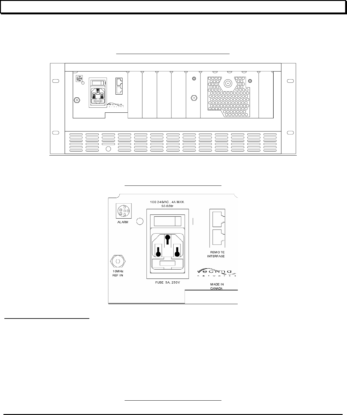
4.1 MA4011B – AC Power/Control Module
DIAGRAM 4.1A : REAR PANEL – MA4367
AC POWER ENTRY MODULE
The AC input accepts input from 100 – 240 VAC. The fuse is internal to the IEC holder. If the fuse requires replacement, ensure
the voltage and current rating is correct. Turn off the AC power switch and then remove the AC cord to power off the chassis.
4.1 MA4012B – DC Power/Control Module
DIAGRAM 4.1B : REAR PANEL – MA4367
ma4367_ml_03_sd Approved: B.G. 21
Vecima Networks Inc.
48V - - -
RS232/RS485
MADE IN
CANADA
36-60VDC, 9A MAX.
ALARM
10MHz
REF IN
REMOTE
INTERFACE
FUSE 10A
60VDC
DC INPUT
The DC input accepts input voltages from 36 to 60 VDC. An indicating fuse is included which exposes a marker if the fuse is
blown. If the fuse requires replacement, ensure the voltage and current rating is correct. The fuse type is a 10 Amp, 125VDC
indicating telecom-style fuse. Suggested part numbers are Bussman GMT-10 or Littlefuse 0481010. The fuse mounts with the
indicator to the right. The DC power switch may be used for turning the power on and off to the entire chassis.
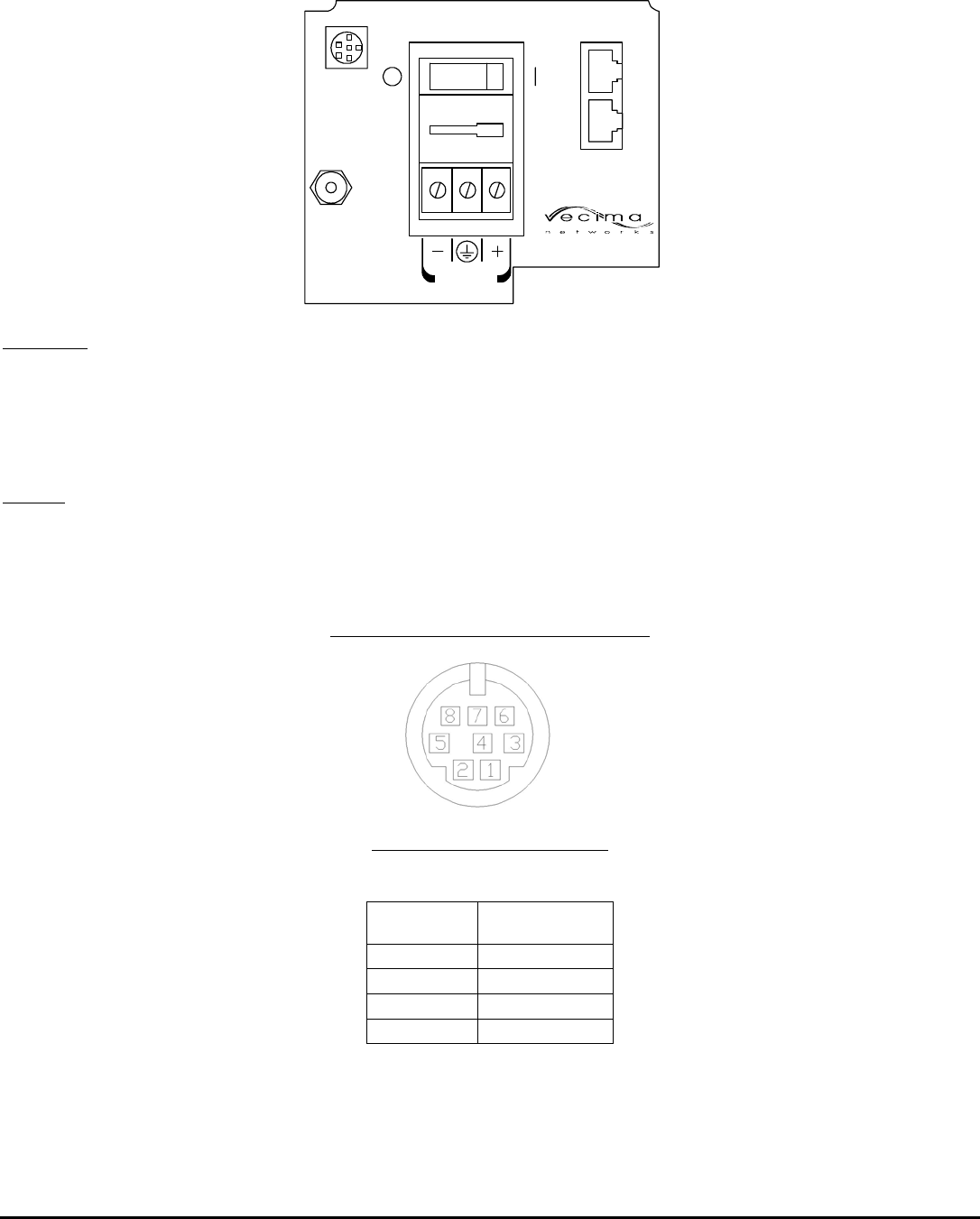
ALARM
This connector is used for an external alarm monitor. It is an 8-pin miniature circular connector. The indicated pins are
connected to a dry-contact relay that is active when an alarm is present in the chassis. See Table 4.1A and Diagram 4.1B for
the connector pin descriptions.
DIAGRAM 4.1B : ALARM SOCKET CONNECTIONS
TABLE4.1A : ALARM SOCKET PINOUT
Pin Number Function
5 Common
6 Normally closed
7 Normally open
1, 2, 3, 4, 8 Not connected
ma4367_ml_03_sd Approved: B.G. 22
Vecima Networks Inc.
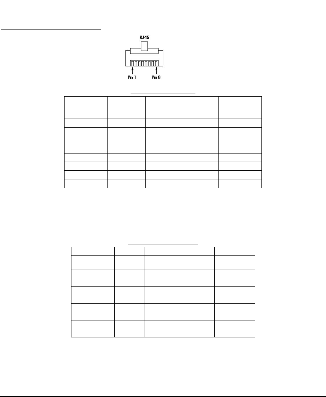
REMOTE INTERFACE
The Remote Interface connector is a dual RJ45. The upper socket is used for the Ethernet interface with the lower socket used
for RS232 or RS485. The pin-out for the matching RJ45 plug is shown in the following table and diagram:
DIAGRAM 4.1C : RJ45 PLUG CONNECTIONS
TABLE 4.1B : RS232 PIN-OUT
Terminal Upconverter
RJ45 Pin Signal Direction Signal RJ45 Pin
1 CTS
← CTS 1
2 DSR
← DSR 2
3 RXD
← TXD 3
4 RXD/GND — RXD/GND 4
5 TXD/GND — TXD/GND 5
6 TXD
→ RXD 6
7 DTR
→ DTR 7
8 RTS
→ RTS 8
( Note: The above pin-out allows a straight through RJ45 cable to be used for connection between the
terminal and the MA4003 chassis. It is also possible to use an RJ45 - DB25 adapter to connect to a PC or
similar RS232 standard serial port.
TABLE 4.1C: RS485 PIN-OUT
Terminal Upconverter
RJ45 Pin Signal Direction Signal RJ45 Pin
1 NC
NC 1
2 NC NC 2
3 A
↔ A 3
4 GND — GND 4
5 GND — GND 5
6 B
↔ B 6
7 NC NC 7
8 NC NC 8
( Note: The above pin-out allows connection to an RS485 communications bus. If desired, an RS485 -
RS232 converter and an RJ45 - DB25 adapter can be used to connect to a PC or similar RS232 serial port.
ma4367_ml_03_sd Approved: B.G. 23
Vecima Networks Inc.
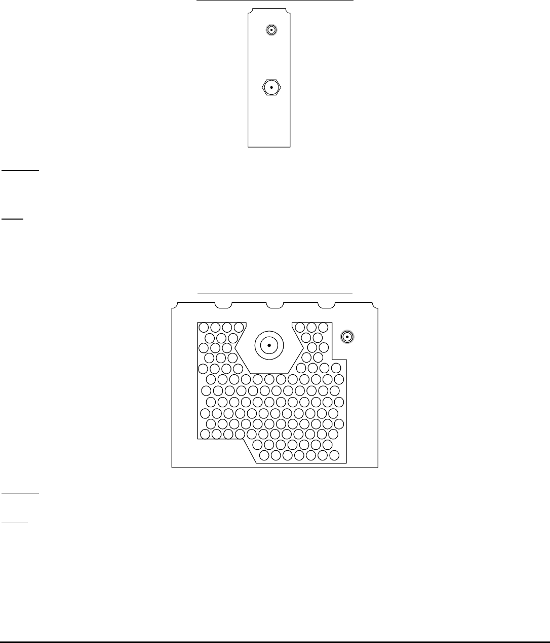
4.2 MA4061B - MMDS Upconverter Card
DIAGRAM 4.2A : REAR PANEL – MA4367
RF OUT
The RF out SMA connector provides the RF output signal from 2505 to 2681 MHz with a level of -15 to 3 dBm. The impedance
is 50 ohm.
IF IN
The IF Input F connector accepts an input signal at 44 MHz with up to a 6 MHz bandwidth from a 75 ohm source. The level
should be from +25 to +35 dBmV.
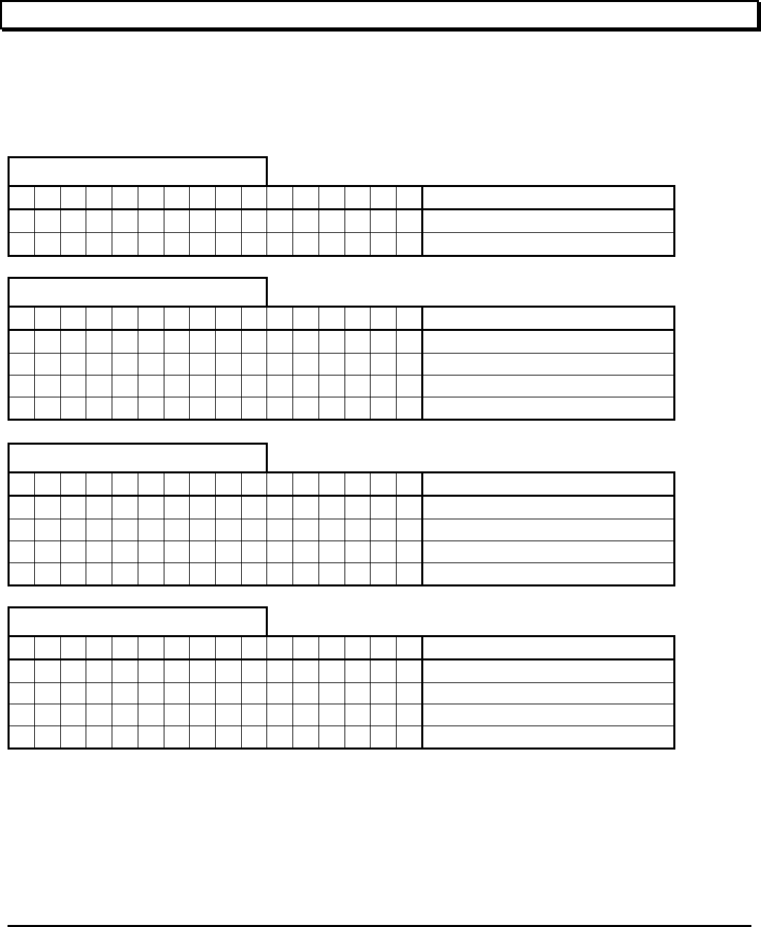
4.3 MA4070C - Power Amplifier
DIAGRAM 4.3A: REAR PANEL – MA4367
RF OUT
The RF output N connector provides the RF output signal from 2505 to 2681 MHz. The impedance is 50 ohm
RF IN
The RF Input SMA connector accepts an input signal at 2505 to 2681 MHz with up to a 6 MHz bandwidth from a 50 ohm
source.
RF OUT RF IN
MMDS
POWER AMPLIFIER
Vecima Networks
MA4070C
RF OUT
IF IN
MMDS DIGITAL
UPCONVERTER
Vecima Networks
MA4061B
ma4367_ml_03_sd Approved: B.G. 24
Vecima Networks Inc.
5.0 STATUS AND ERROR CODES
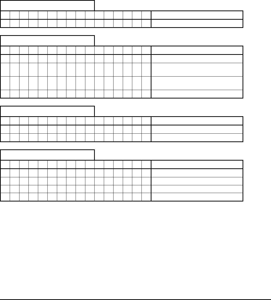
5.1 MA4061B Status and Error Codes
The status and error codes are displayed on line 2 of the LCD display. They consist of an ‘s’ or ‘e’ character followed by a 2
digit hexadecimal number. The following tables can be used to interpret the meaning of the digits. For example, a display of
s02 e40 indicates that IF AGC is enabled and there is an IF Threshold error. If there are no errors, the error code will not be
displayed, and only the status will be visible.
Status Code Left Digit
0 1 2 3 4 5 6 7 8 9 A B C D E F Status
•
Backup relay enabled
• • • • • • • • • • • • • • Unused
Status Code Right Digit
0 1 2 3 4 5 6 7 8 9 A B C D E F Status
• • • • • • • • Output is disabled
• •
• •
• •
• • IF AGC is enabled
• • • •
• • • • IF threshold detection is enabled
• • • • • • • • RF threshold detection is enabled
Error Code Left Digit
0 1 2 3 4 5 6 7 8 9 A B C D E F Status
• • • • • • • • Fixed LO error
• •
• •
• •
• • IF AGC error
• • • •
• • • • IF threshold error
• • • • • • • • RF threshold error
Error Code Right Digit
0 1 2 3 4 5 6 7 8 9 A B C D E F Status
• • • • • • • • Output is muted
• •
• •
• •
• • Hard alarm condition
• • • •
• • • • Soft alarm condition
• • • • • • • • Variable LO error
ma4367_ml_03_sd Approved: B.G. 25
Vecima Networks Inc.
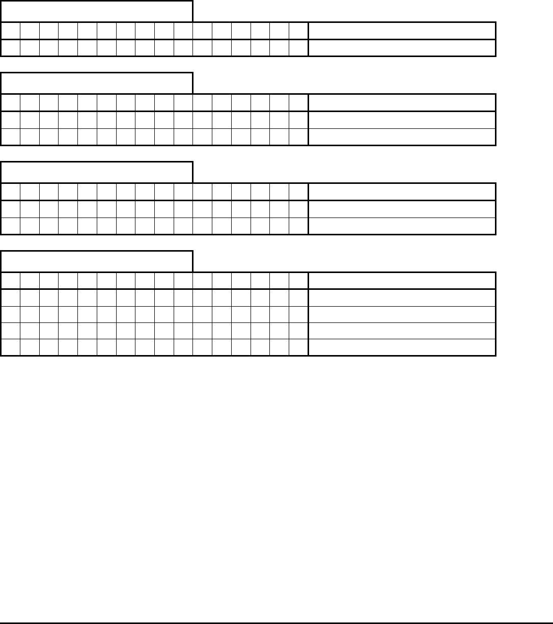
5.2 MA4070C Status and error Codes
The status and error codes are displayed on line 2 of the LCD display. They consist of an ‘s’ or ‘e’ character followed by a 2
digit hexadecimal number. The following tables can be used to interpret the meaning of the digits. If there are no errors, the
error code will not be displayed, and only the status will be visible.
Status Code Left Digit
0 1 2 3 4 5 6 7 8 9 A B C D E F Status
• • • • • • • • • • • • • • • Unused
Status Code Right Digit
0 1 2 3 4 5 6 7 8 9 A B C D E F Status
• • • • • • • • Output is disabled
• •
• •
• •
• • Forward power high threshold
detection is enabled
• • • •
• • • • Forward power low threshold
detection is enabled
• • • • • • • • RF threshold detection is enabled
Error Code Left Digit
0 1 2 3 4 5 6 7 8 9 A B C D E F Status
•
Reverse power threshold error
• • • • • • • • • • • • • • Unused
Error Code Right Digit
0 1 2 3 4 5 6 7 8 9 A B C D E F Status
• • • • • • • • Hard alarm condition
• •
• •
• •
• • Soft alarm condition
• • • •
• • • • Forward power high threshold error
• • • • • • • • Forward power low threshold error
ma4367_ml_03_sd Approved: B.G. 26
Vecima Networks Inc.
5.3 MA4011B Power/Control Module Status and Error Codes
The status and error codes are displayed on line 2 of the LCD display. They consist of an ‘s’ or ‘e’ character followed by a 2
digit hexadecimal number. The following tables can be used to interpret the meaning of the digits. If there are no errors, the
error code will not be displayed, and only the status will be visible.
Status Code Left Digit
0 1 2 3 4 5 6 7 8 9 A B C D E F Status
• • • • • • • • • • • • • • • Unused
Status Code Right Digit
0 1 2 3 4 5 6 7 8 9 A B C D E F Status
•
Local control locked out
• • • • • • • • • • • • • • Unused
Error Code Left Digit
0 1 2 3 4 5 6 7 8 9 A B C D E F Status
•
5 Volt supply under voltage
• • • • • • • • • • • • • • Unused
Error Code Right Digit
0 1 2 3 4 5 6 7 8 9 A B C D E F Status
• • • • • • • • Hard alarm condition
• •
• •
• •
• • Unused
• • • •
• • • • 24 Volt supply under voltage
• • • • • • • • 10 Volt supply under voltage

ma4367_ml_03_sd Approved: B.G. 27
Vecima Networks Inc.
6.0 DETAILED REMOTE CONTROL
6.1 Operation
The MA4367 system may be controlled via the RS232/RS485 Remote Interface connector. (See Section 4.1,
Power/Control Module Rear Panel Connections for the connector pin-out).
The input data rate can be 9600, 14400, or 28800 baud. The MA4000 System Controller will automatically determine which
data rate is in use and adjust accordingly. There are no user settings relating to baud rate selection.
6.2 Message Format
All messages to the MA4000 system controller consist of a sequence of ASCII characters. Messages must meet the
following guidelines in order to be correctly interpreted by the controller.
• There can be no more than 75 ms between consecutive message bytes.
• After receiving the entire message, the MA4000 System Controller will require approximately 200 ms to process and respond to
the message.
• Only one message can be processed at a time, consequently the user must wait for a reply before sending a new message.
• Commands sent to an invalid chassis address will be discarded without a response.
6.3 Command Structure
The command structure consists of a sequence of ASCII characters terminated by a carriage return. All ASCII characters
are case-insensitive unless otherwise indicated. Commands are to be in one of the following two general formats:
<start>ADD<sp>MOD<sp>CC<sp>CRC<cr>
or
<start>ADD<sp>MOD<sp>CC<sp>PARM<sp>CRC<cr>
<start> ASCII Asterisk character
<sp> ASCII Space character
<cr> ASCII Carriage Return character
ADD = Address (3 ASCII characters)
Addresses are 3 digit numbers. Three digits (including leading zeros) are required to correctly define an address.
MOD = Module (1 ASCII character)
A = Module A (Leftmost module)
B = Module B
.
.
J = Module J (Next to Power Control Module)
CC = Command Code (2 or 3 ASCII characters)

ma4367_ml_03_sd Approved: B.G. 28
Vecima Networks Inc.
MA4061B Command Codes
FL = Load Frequency IAS = Set IF AGC Threshold
AI = Set IF Attenuation IAE = Enable IF AGC Threshold
AR = Set RF Attenuation IAD = Disable IF AGC Threshold
OE = Enable Output RTS = Set RF Threshold
OD = Disable Output RTD = Disable RF Threshold
ITS = Set IF Threshold RTE = Enable RF Threshold
ITD = Disable IF Threshold SU = Unit Status Request
ITE = Enable IF Threshold LE = Enable Local Control
LD = Disable Local Control
MA4070C Command Codes
OE = Enable Output FPHS = Forward Power High Set
OD = Disable Output FPHE = Forward Power Hi Enable
SU = Unit Status Request FPHD = Forward Power High Disable
SC = Configuration Status Request FPLS = Forward Power Low Set
LE = Enable Local Control FPLE = Forward Power Low Enable
LD = Disable Local Control FPLD = Forward Power Low Disable
RPS = Reverse Power Threshold Set
RPE = Reverse Power Threshold Enable
RPE = Reverse Power Threshold Disable
CRC = CRC-16 checksum (3 characters)
The checksum is preferred, but not required. If the checksum is used, the first character is an ASCII “V” followed by the low and high
bytes respectively of the computed CRC 16 checksum (the checksum characters are not necessarily ASCII). The checksum is to be
computed on all characters after the initial <start> character up to, and including, the first “V” character in the CRC section. If the
checksum is not used, the 3 characters should be ASCII “NNN” (they must be uppercase).
PARM is one or more characters, and is command specific.

ma4367_ml_03_sd Approved: B.G. 29
Vecima Networks Inc.
6.4 Response Structure
The response structure will consist of a sequence of ASCII characters, terminated by a carriage return. Responses will be
in one of the two following general formats:
<start>ADD<sp>R<sp>RC<sp>CRC<cr>
or
<start>ADD<sp>R<sp>RC<sp>PARM<sp>CRC<cr>
There will be one response returned for all commands.
<start> ASCII Asterisk character
<sp> ASCII Space character
<cr> ASCII Carriage Return character
ADD = Address (3 characters)
The address of the unit that is responding to the command.
R = ASCII “R” character (1 character)
Indicates that this is a response to a previous message.
RC = Response Code (3 characters)
OK = Command Accepted
MOD = Command Denied because the addressed module is invalid
ERR = Command Denied because of Syntax Error
CRC = Command Denied because of CRC-16 error
CRC = CRC-16 checksum (3 characters)
The response checksum is always valid. The first character will be an ASCII “V” followed by the low and high bytes
respectively of the computed CRC 16 checksum (the checksum characters are not necessarily ASCII). The checksum will be
computed on all characters after the initial <start> character up to, and including, the first “V” character in the CRC section.
PARM is one or more characters, and is command specific.

ma4367_ml_03_sd Approved: B.G. 30
Vecima Networks Inc.
6.5 Detailed Command Descriptions and System Responses
6.5.1 MA4061B Upconverter Detailed Command Descriptions and System Responses
This section defines each of the command codes and the associated parameters for the MA4061B Upconverter module.
FL - Load Frequency
Description: Loads the frequency for the specified module.
Parameters: Desired frequency in MHz, in the form XXXX.XXXX. Leading zeros are optional, but not required. The decimal point
and four trailing characters are required. Valid input frequencies are between 2505.0000 MHz and 2681.0000 MHz.
Valid trailing characters are multiples of 0.0625 MHz, all others will be denied.
Example: *999<sp>A<sp>FL<sp>2500.0625<sp>CRC<cr>
Response: OK or MOD or ERR or CRC
AI - Set IF Attenuation
Description: Sets the IF attenuation for the specified module.
Parameters: Desired IF attenuation in dB, in the form XX.XX. Leading zeros are optional, but not required. The decimal point and
two trailing characters are required. Valid attenuation values are between 0 dB and 25 dB in 0.25 dB steps. Valid
trailing characters are 00, 25, 50 or 75.
Example: *999<sp>A<sp>AI<sp>10.50<sp>CRC<cr>
Response: OK or MOD or ERR or CRC
AR - Set RF Attenuation
Description: Sets the RF attenuation for the specified module.
Parameters: Desired RF output attenuation in dB, in the form XX.XX. Leading zeros are optional, but not required. The decimal
point and two trailing characters are required. Valid attenuation values are between 0 dB and 39.75 dB in 0.25 dB
steps. Valid trailing characters are 00, 25, 50 or 75.
Example: *999<sp>A<sp>AR<sp>4.25<sp>CRC<cr>
Response: OK or MOD or ERR or CRC
ITS - Set IF Threshold
Description: Sets the IF thresholds for the specified module.
Parameters: Desired IF thresholds in dB, in the form X.X<sp>-X.X. Leading zeros are optional, but not required. The decimal point
and trailing character is required. The first parameter is the positive threshold and can range between 4.0 and 0.0 dB.
The second parameter is the negative threshold and can range between 0.0 and -4.0 dB. The trailing character can
range between 0.0 and 0.9.
Example: *999<sp>A<sp>ITS<sp>1.5<sp>-1.5<sp>CRC<cr>
Response: OK or MOD or ERR or CRC
ITE - Enable IF Threshold
Description: Enables IF Threshold detection for the specified module.
Parameters: None
Example: *999<sp>A<sp>ITE<sp>CRC<cr>
Response: OK or MOD or ERR or CRC

ma4367_ml_03_sd Approved: B.G. 31
Vecima Networks Inc.
ITD - Disable IF Threshold
Description: Disables IF Threshold detection for the specified module.
Parameters: None
Example: *999<sp>A<sp>ITD<sp>CRC<cr>
Response: OK or MOD or ERR or CRC
IAS - Set Auto IF Threshold
Description: Sets the Auto IF Thresholds for the specified module.
Parameters: Desired IF thresholds in dB, in the form X.X<sp>-X.X. Leading zeros are optional, but not required. The decimal point
and trailing character is required. The first parameter is the positive threshold and can range between 4.0 and 0.0 dB.
The second parameter is the negative threshold and can range between 0.0 and -4.0 dB. The trailing character can
range between 0.0 and 0.9.
Example: *999<sp>A<sp>IAS<sp>1.5<sp>-1.5<sp>CRC<cr>
Response: OK or MOD or ERR or CRC
IAE - Enable Auto IF
Description: Enables Auto IF Mode for the specified module.
Parameters: None
Example: *999<sp>A<sp>IAE<sp>CRC<cr>
Response: OK or MOD or ERR or CRC
IAD - Disable Auto IF
Description: Disables Auto IF Mode for the specified module.
Parameters: None
Example: *999<sp>A<sp>IAD<sp>CRC<cr>
Response: OK or MOD or ERR or CRC
RTS - Set RF Threshold
Description: Sets the RF Thresholds for the specified module.
Parameters: Desired RF thresholds in dBm, in the form XX.X<sp>XX.X. Leading zeros are optional, but not required. The decimal
point and trailing character is required. The first parameter indicates the high threshold, and the second indicates the
low threshold. The trailing character can range between 0.0 and 0.9.
Example: *999<sp>A<sp>RTS<sp>60.0<sp>50.0<sp>CRC<cr>
Response: OK or MOD or ERR or CRC
RTE - Enable RF Threshold
Description: Enables RF Threshold detection for the specified module.
Parameters: None
Example: *999<sp>A<sp>RTE<sp>CRC<cr>
Response: OK or MOD or ERR or CRC
RTD - Disable RF Threshold
Description: Disables RF Threshold detection for the specified module.
Parameters: None

ma4367_ml_03_sd Approved: B.G. 32
Vecima Networks Inc.
Example: *999<sp>A<sp>RTD<sp>CRC<cr>
Response: OK or MOD or ERR or CRC
OE - Enable Output
Description: Turns on the Output from the specified module.
Parameters: None
Example: *999<sp>A<sp>OE<sp>CRC<cr>
Response: OK or MOD or ERR or CRC
OD - Disable Output
Description: Turns off the Output from the specified module.
Parameters: None
Example: *999<sp>A<sp>OD<sp>CRC<cr>
Response: OK or MOD or ERR or CRC
LE - Enable Local Control
Description: Enables local control of the MA4367 system. The module address must indicate a valid module even though the
command does not change any module settings.
Parameters: None
Example: *999<sp>A<sp>LE<sp>CRC<cr>
Response: OK or MOD or ERR or CRC
LD - Disable Local Control
Description: Disables local control of the MA4367 system. The module address must indicate a valid module even though the
command does not change any module settings.
Parameters: None
Example: *999<sp>A<sp>LD<sp>CRC<cr>
Response: OK or MOD or ERR or CRC
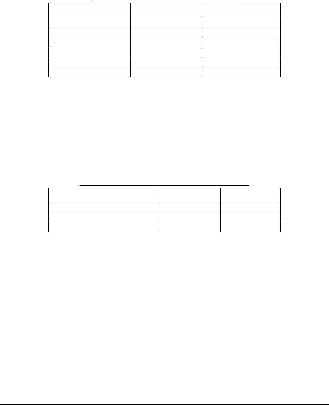
SU - Status Unit Request
Description: The Status Unit Request command returns the factory model and revision history for the specified module. The
detailed contents of the reply are shown in the response section.
Parameters: None
Example: *999<sp>A<sp>SU<sp>CRC<cr>
Response: OK or MOD or ERR or CRC
If the response is OK, then the following parameters will also be returned in the order shown below. (Note: X may be
replaced by any valid character. All other characters will be as shown).
TABLE 6.5.1A : RESPONSE PARAMETERS FOR STATUS UNIT REQUEST
Parameter (Units) Format Example
Model XXXXXXXXXXX Upconverter
Module SN XXXXXXX 0123456
Hardware Revision XXX 010 (i.e. Rev 1.0)
Microcontroller Revision XXX 010 (i.e. Rev 1.0)
PLD Revision XXX 010 (i.e. Rev 1.0)

ma4367_ml_03_sd Approved: B.G. 33
Vecima Networks Inc.
Miscellaneous 16 chars

ma4367_ml_03_sd Approved: B.G. 34
Vecima Networks Inc.
6.5.2 MA4070C Power Amplifier Detailed Command Descriptions and System Responses
This section defines each of the command codes and the associated parameters for the MA4070C Power Amplifier module.
OE - Enable Output
Description: Turns on the Output from the specified module.
Parameters: None
Example: *999<sp>A<sp>OE<sp>CRC<cr>
Response: OK or MOD or ERR or CRC
OD - Disable Output
Description: Turns off the Output from the specified module.
Parameters: None
Example: *999<sp>A<sp>OD<sp>CRC<cr>
Response: OK or MOD or ERR or CRC
LE - Enable Local Control
Description: Enables local control of the MA4367 system. The module address must indicate a valid module even though the
command does not change any module settings.
Parameters: None
Example: *999<sp>A<sp>LE<sp>CRC<cr>
Response: OK or MOD or ERR or CRC
LD - Disable Local Control
Description: Disables local control of the MA4367 system. The module address must indicate a valid module even though the
command does not change any module settings.
Parameters: None
Example: *999<sp>A<sp>LD<sp>CRC<cr>
Response: OK or MOD or ERR or CRC
SU - Status Unit Request
Description: The Status Unit Request command returns the factory model and revision history for the specified module. The
detailed contents of the reply are shown in the response section.
Parameters: None
Example: *999<sp>A<sp>SU<sp>CRC<cr>
Response: OK or MOD or ERR or CRC
If the response is OK, then the following parameters will also be returned in the order shown below. (Note: X may be
replaced by any valid character. All other characters will be as shown).
ma4367_ml_03_sd Approved: B.G. 35
Vecima Networks Inc.
TABLE 6.5.2A : RESPONSE PARAMETERS FOR STATUS UNITS REQUEST
Parameter (Units) Format Example
Model XXXXXXXXXXX MA4070C
Module SN XXXXXXX 0123456
Hardware Revision XXX 010 (i.e. Rev 1.0)
Microcontroller Revision XXX 010 (i.e. Rev 1.0)
Miscellaneous 16 chars
SC - Status Configuration Request
Description: The Status Configuration Request command returns the active configuration, including error codes and alarm status
for the addressed module. It also returns the current status of the power supply module. The detailed contents of the
reply are shown in the response section.
Parameters: None
Example: *999<sp>A<sp>SC<sp>CRC<cr>
Response: OK or ERR or CRC or MOD
If the response is OK, then the following parameters will also be returned in space delimited format in the order
shown below. (Note: X may be replaced by any valid character. All other characters will be as shown). Error codes
are the last two digits reported on the status code line. Refer to Section 6.0, Error Codes for more details.
TABLE6.5.2B : RESPONSE PARAMETERS FOR STATUS CONFIGURATION REQUEST
Parameter (Units) Format Example
MA4070C Status Code XXXX 0101
MA4070C RF Power (dBm) XXX.X 31.5
MA4070C RF Reverse Power (dBm) XX.X < 20
FPHS – Forward Power High Set
Description: Sets the Forward Power High for the specified module. When the Forward Power High is enabled, and the RF Power
is above the threshold limit, a non-critical alarm will be triggered.
Parameters: Desired RF Thresholds in dBm, in the form XX.X. The decimal point and trailing characters are required. The trailing
character can range between 0.0 and 0.9
Example: *999<sp>B<sp>FPHS<sp>38.0<sp>CRC<cr>
Response: OK or MOD or ERR or CRC
FPHE – Enable Forward Power High
Description: Enables the Forward Power High for the specified module. When the Forward Power High is enabled, and the RF
Power is above the threshold limit, a non-critical alarm will be triggered.
Parameters: None
Example: *999<sp>B<sp>FPHE<sp>CRC<cr>
Response: OK or MOD or ERR or CRC

ma4367_ml_03_sd Approved: B.G. 36
Vecima Networks Inc.
FPHD – Disable Forward Power High
Description: Disables the Forward Power High for the specified module.
Parameters: None
Example: *999<sp>B<sp>FPHD<sp>CRC<cr>
Response: OK or MOD or ERR or CRC
FPLS – Set Forward Power Low
Description: Sets the Forward Power Low for the specified module. When the Forward Power Low is enabled, and the RF Power
is below the threshold limit, a non-critical alarm will be triggered.
Parameters: Desired RF Thresholds in dBm, in the form XX.X. The decimal point and trailing characters are required. The trailing
character can range between 0.0 and 0.9
Example: *999<sp>B<sp>FPLS<sp>34.0<sp>CRC<cr>
Response: OK or MOD or ERR or CRC
FPLE – Enable Forward Power Low
Description: Enables the Forward Power Low for the specified module. When the Forward Power Low is enabled, and the RF
Power is below the threshold limit, a non-critical alarm will be triggered.
Parameters: None
Example: *999<sp>B<sp>FLPE<sp>CRC<cr>
Response: OK or MOD or ERR or CRC
FPLD – Disable Forward Power Low
Description: Disables the Forward Power Low for the specified module.
Parameters: None
Example: *999<sp>B<sp>FPLD<sp>CRC<cr>
Response: OK or MOD or ERR or CRC
RPS – Set Reverse Power Threshold
Description: Sets the Reverse Power Threshold for the specified module. When the Reverse Power Threshold is enabled, and
the RF Power is above the threshold limit, a non-critical alarm will be triggered.
Parameters: Desired RF Thresholds in dBm, in the form XX.X. The decimal point and trailing characters are required. The trailing
character can range between 0.0 and 0.9
Example: *999<sp>B<sp>RPS<sp>25.0<sp>CRC<cr>
Response: OK or MOD or ERR or CRC
RPE – Enable Reverse Power Threshold
Description: Sets the Reverse Power Threshold for the specified module. When the Reverse Power Threshold is enabled, and
the RF Power is above the threshold limit, a non-critical alarm will be triggered.
Parameters: None
Example: *999<sp>B<sp>RPE<sp>CRC<cr>
Response: OK or MOD or ERR or CRC
RPD – Disable Reverse Power Threshold
Description: Disables the Reverse Power Threshold for the specified module.
Parameters: None
Example: *999<sp>B<sp>RPD<sp>CRC<cr>
Response: OK or MOD or ERR or CRC

ma4367_ml_03_sd Approved: B.G. 37
Vecima Networks Inc.
6.6 CRC Calculation
The CRC calculations are performed using a table driven approach. The polynomial used is X^16+X^15+X^2+1.
Only the basic algorithm and lookup table will be described here. Sample code is available on request. For further information,
this approach is described in detail in the following paper:
Perez, Aram; Byte-wise CRC Calculations, IEEE Micro, June 1983, pp. 40 - 50
The algorithm for the CRC calculation is as follows:
Exclusive-OR the input byte with the low-order byte of the CRC register to get X.
Shift the CRC register 8 bits to the right.
Exclusive-OR the CRC register with the contents of the table, using X as an index.
Repeat steps 1 - 3 for all message bytes.
( Note: The CRC register is 16 bits long, and should be cleared to 0 before beginning the calculations.
For the transmit message: After all the message bytes have been processed, the CRC is tagged on to the end of the
message with the least significant byte first.
For the received message: After all the received message bytes have been processed, the resulting CRC should be zero. If it
is not zero, at least one bit error has occurred. If it is zero, it is assumed that no errors have occurred.

ma4367_ml_03_sd Approved: B.G. 38
Vecima Networks Inc.
7.0 WARRANTY AND SERVICE POLICIES
7.1 Warranty Statement
Vecima warrants its products to be free from defects in workmanship or materials for a period of two years. The warranty
begins on the date of the original shipment from Vecima to its customer. No claim may be allowed for expenses incurred in
installation or use. No other expressed or implied warranties shall apply to the goods sold. Vecima is not responsible for
delayed shipments, other loss beyond Vecima’s control, or consequential damages of any kind arising in connection with the
use of its products. This warranty is a return-to-factory warranty only. During the warranty period Vecima will at its option,
replace, repair or refund the price paid for any item which is returned for service. This warranty does not apply to units that
have been physically or environmentally abused.
7.2 Service Policies: How to Return an Item for Service:
Before returning any item for service, an R.M.A. (Returned Material Authorization) number must be assigned by Vecima. A
unique R.M.A. number will be assigned for each item being returned. When requesting an R.M.A. number, please be prepared
to provide the model, Vecima serial number, original invoice number, your purchase order number and an adequate fault
description. The serial number of a unit can be found on a barcode label similar to the one pictured below. R.M.A. service is
available Monday to Friday from 8:30 a.m. to 4:30 p.m. CST (statutory holidays excepted).
To obtain an R.M.A. number you may:
Call: (306) 955-7075, press ‘0’ for Operator, or ‘3’ for Service Dept.
Fax: (306) 384-0086 — Attention: R.M.A. Request
Email: support@vecimanetworks.com
Once an R.M.A. number has been assigned, please refer to it in all correspondence and make certain that all applicable R.M.A.
numbers are clearly marked on the outside of each package being returned. You must also ensure that each product is
shipped to Vecima in its original shipping container (or equivalent) via Prepaid carrier, with appropriate insurance and customs
documentation (where required). Vecima will not accept collect shipments, damaged shipments or shipments unaccompanied
by an R.M.A. number.
For items still under Warranty – Items will be returned from Vecima Inc. to its customer via prepaid ground carrier. The
customer is responsible for any additional costs incurred, including custom clearance and duties. Any alternate means of
shipment must be requested by the customer and will be subject to additional charges.
For items no longer under Warranty – Items will be returned from Vecima Inc. to its customer via prepaid ground carrier at
the customer’s expense. The customer is responsible for any additional costs incurred, including custom clearance and duties.
Any alternate means of shipment must be requested by the customer and will be subject to additional charges.
Shipping Instructions will be provided by the repair center when the RMA number is sent to the customer.

ma4367_ml_03_sd Approved: B.G. 39
Vecima Networks Inc.
7.3 Repair Charges and Warranty Exemptions
Items returned beyond the warranty period or items that do not qualify for warranty service are subject to additional out-of-
warranty repair charges. Descriptions of these charges and warranty exemptions are below:
1) Repair turnaround time is typically 5-14 business days after receipt of the item at Vecima.
A Flat Rate Repair Charge will apply to all out-of-warranty items. Flat Rate Repair Charges are subject to change
without notice.
2) Any faults due to customer error (ie - incorrect set-up or configuration settings) are subject to the current Test Fee and
will be exempt from warranty.
3) Items returned with inadequate fault descriptions are subject to the current Test Fee.
4) In the event that no fault is found, the item is subject to the current Test Fee and will be
exempt from warranty.
5) Any product exhibiting external damage (either from shipping, improper handling or use) will be subject to inspection. If
said damages are determined to be the cause of failure, the item will be exempt from warranty.
All repairs to correct the external damage are subject to Time & Materials Charges (parts and labor at current rates).
6) Items with damage caused by unauthorized repairs or by external devices are subject to current out-of-warranty Flat
Rate Repair Charges and are exempt from warranty.
7) All products returned for Factory Optioning are subject to the applicable current Option Charge plus Test Fee. Factory-
optioned products carry the balance of the original warranty or a 90 day warranty, whichever is greater.
All out-of-warranty repairs and test fees must be approved by the customer in writing. No repairs will be made until the
customer’s Purchase Order or Out-Of-Warranty Repair Authorization is received.

ma4367_ml_03_sd Approved: B.G. 40
Vecima Networks Inc.
APPENDIX A – CRC – 16 CALCULATIONS TABLE
All values in the table are in Hex format.
X TERM ENTRY X TERM ENTRY
X
TERM ENTRY
X
TERM ENTRY X TERM ENTRY
0 0 33 1540 66 2A80 99 6AC0 CC 5500
1 C0C1 34 D701 67 EA41 9A 6B80 CD 95C1
2 C181 35 17C0 68 EE01 9B AB41 CE 9481
3 140 36 1680 69 2EC0 9C 6900 CF 5440
4 C301 37 D641 6A 2F80 9D A9C1 D0 9C01
5 3C0 38 D201 6B EF41 9E A881 D1 5CC0
6 280 39 12C0 6C 2D00 9F 6840 D2 5D80
7 C241 3A 1380 6D EDC1 A0 7800 D3 9D41
8 C601 3B D341 6E EC81 A1 B8C1 D4 5F00
9 6C0 3C 1100 6F 2C40 A2 B981 D5 9FC1
A 780 3D D1C1 70 E401 A3 7940 D6 9E81
B C741 3E D081 71 24C0 A4 BB01 D7 5E40
C 500 3F 1040 72 2580 A5 7BC0 D8 5A00
D C5C1 40 F001 73 E541 A6 7A80 D9 9AC1
E C481 41 30C0 74 2700 A7 BA41 DA 9B81
F 440 42 3180 75 E7C1 A8 BE01 DB 5B40
10 CC01 43 F141 76 E681 A9 7EC0 DC 9901
11 CC0 44 3300 77 2640 AA 7F80 DD 59C0
12 D80 45 F3C1 78 2200 AB BF41 DE 5880
13 CD41 46 F281 79 E2C1 AC 7D00 DF 9841
14 F00 47 3240 7A E381 AD BDC1 E0 8801
15 CFC1 48 3600 7B 2340 AE BC81 E1 48C0
16 CE81 49 F6C1 7C E101 AF 7C40 E2 4980
17 E40 4A F781 7D 21C0 B0 B401 E3 8941
18 A00 4B 3740 7E 2080 B1 74C0 E4 4B00
19 CAC1 4C F501 7F E041 B2 7580 E5 8BC1
1A CB81 4D 35C0 80 A001 B3 B541 E6 8A81
1B B40 4E 3480 81 60C0 B4 7700 E7 4A40
1C C901 4F F4441 82 6180 B5 B7C1 E8 4E00
1D 9C0 50 3C00 83 A141 B6 B681 E9 8EC1
1E 880 51 FCC1 84 6300 B7 7640 EA 8F81
1F C841 52 FD81 85 A3C1 B8 7200 EB 4F40
20 D801 53 3D40 86 A281 B9 B2C1 EC 8D01
21 18C0 54 FF01 87 6240 BA B381 ED 4DC0
22 1980 55 3FC0 88 6600 BB 7340 EE 4C80
23 D941 56 3E80 89 A6C1 BC B101 EF 8C41
24 1B00 57 FE41 8A A781 BD 71C0 F0 4400
25 DBC1 58 FA01 8B 6740 BE 7080 F1 84C1
26 DA81 59 3AC0 8C A501 BF B041 F2 8581
27 1A40 5A 3B80 8D 65C0 C0 5000 F3 4540
28 1E00 5B FB41 8E 6480 C1 90C1 F4 8701
29 Dec-01 5C 3900 8F A441 C2 9181 F5 47C0
2A DF81 5D F9C1 90 6C00 C3 5140 F6 4680
2B 1F40 5E F881 91 ACC1 C4 9301 F7 8641
2C DD01 5F 3840 92 AD81 C5 53C0 F8 8201
2D 1DC0 60 2800 93 6D40 C6 5280 F9 42C0
2E 1C80 61 E8C1 94 AF01 C7 9241 FA 4380
2F DC41 62 E981 95 6FC0 C8 9601 FB 8341
30 1400 63 2940 96 6.00E+80 C9 56C0 FC 4100
31 D4C1 64 EB01 97 AE41 CA 5780 FD 81C1
32 D581 65 2BC0 98 AA01 CB 9741 FE 8081
FF 4040

ma4367_ml_03_sd Approved: B.G. 41
Vecima Networks Inc.
APPENDIX B – MA4367 SNMP AGENT CONFIGURATION PROCEDURE
The MA4367 SNMP agent is an optional feature that must be factory installed at time of order
a) Once PC on same 10.10.10.0 network is connected to the unit with a cross-over Ethernet cable try pinging the
unit. This can be done from the DOS prompt.
Microsoft Windows XP [Version 5.1.2600]
(C) Copyright 1985-2001 Microsoft Corp.
C:\>ping 10.10.10.11
Pinging 10.10.10.11 with 32 bytes of data:
Reply from 10.10.10.11: bytes=32 time=1ms TTL=64
Reply from 10.10.10.11: bytes=32 time=1ms TTL=64
Reply from 10.10.10.11: bytes=32 time=1ms TTL=64
Reply from 10.10.10.11: bytes=32 time=2ms TTL=64
Ping statistics for 10.10.10.11:
Packets: Sent = 4, Received = 4, Lost = 0 (0% loss),
Approximate round trip times in milli-seconds:
Minimum = 1ms, Maximum = 2ms, Average = 1ms
b) In order to be sure that you are indeed connected to the right unit check the arp cache. The MAC/physical
address listed for 10.10.10.11 should be the same address listed on the back label of the unit.
C:\>arp -a
Interface: 10.10.10.2 --- 0x10004
Internet Address Physical Address Type
10.10.10.11 00-20-4a-72-1b-5c dynamic
c) In order to access the SNMP Agent configuration menus telnet to 10.10.10.11 9999.
C:\>telnet 10.10.10.11 9999
*** Wavecom SNMP Proxy Agent
Serial Number 7207004 MAC address 00:20:4A:72:1B:5C
Software version V5.20
Press Enter to go into Setup Mode

ma4367_ml_03_sd Approved: B.G. 42
Vecima Networks Inc.
d) Press Enter at the point to load the Setup Mode; the Current Settings will then be displayed.
Current settings:
Hardware: Ethernet Autodetect AUI
IP addr: 010.010.010.011
No gateway set
Netmask: 255.255.255.000--- not set ---
Baudrate: 09600
I/F Mode: 4C
Flow: 00
Chassis addr: 999
SNMPEnable: No
SNMP community name for read:
SNMP community name for write:
Change Setup
0 Basics
1 Connection
2 Community strings
8 Exit
9 Save and exit
Select:
e) As you can see there are 03 main submenus:
0) Basic = SNMP Agent IP Address, subnet mask, IP for SNMP Manager/Traps, password set
Select: 0
IP Address: (010) .(010) .(010) .(011)
Set Gateway IP Address (N) N
Netmask: Number of Bits for Host Part (0=default) (08)
IP Address for SNMP Traps: (000) .(000) .(000) .(000)
Change telnet config password (N) N
1) Connection = Baudrate, I/F Mode, Chassis address, SNMP Enable
Select: 1
Baudrate (09600)
I/F Mode (4C) ?
Flow (00) ?
Chassis address (999) ← Note: must be same as Chassis Address set on MA4012B
SNMPEnable (N) N

ma4367_ml_03_sd Approved: B.G. 43
Vecima Networks Inc.
2) SNMP Community Strings = read and write SNMP Community strings
Select: 2 SNMP community name for read (): public
SNMP community name for write (): private
f) Once all of your required changes have been made select option 9 to Save and Exit. This will reset the SNMP
Agent and the new settings will be effective as soon as it reloads.

150 Cardinal Place
Saskatoon, Saskatchewan, Canada S7L 6H7
Tel: (306) 955-7075
Fax: (306) 955-9919
Web: www.vecimanetworks.com
Email: sales@vecimanetworks.com