Vecima Networks MMT9000 Mobile Wan Vehicle Radio User Manual EUM3005 User Guide
Vecima Networks Inc. Mobile Wan Vehicle Radio EUM3005 User Guide
UserManual.wiki
>
Vecima Networks
>
MMT9000 User Manual
Manual
Navigation menu
Upload a User Manual
Namespaces
Wiki Guide
HTML
PDF
Info
Views
User Manual
Discussion / Help
Navigation
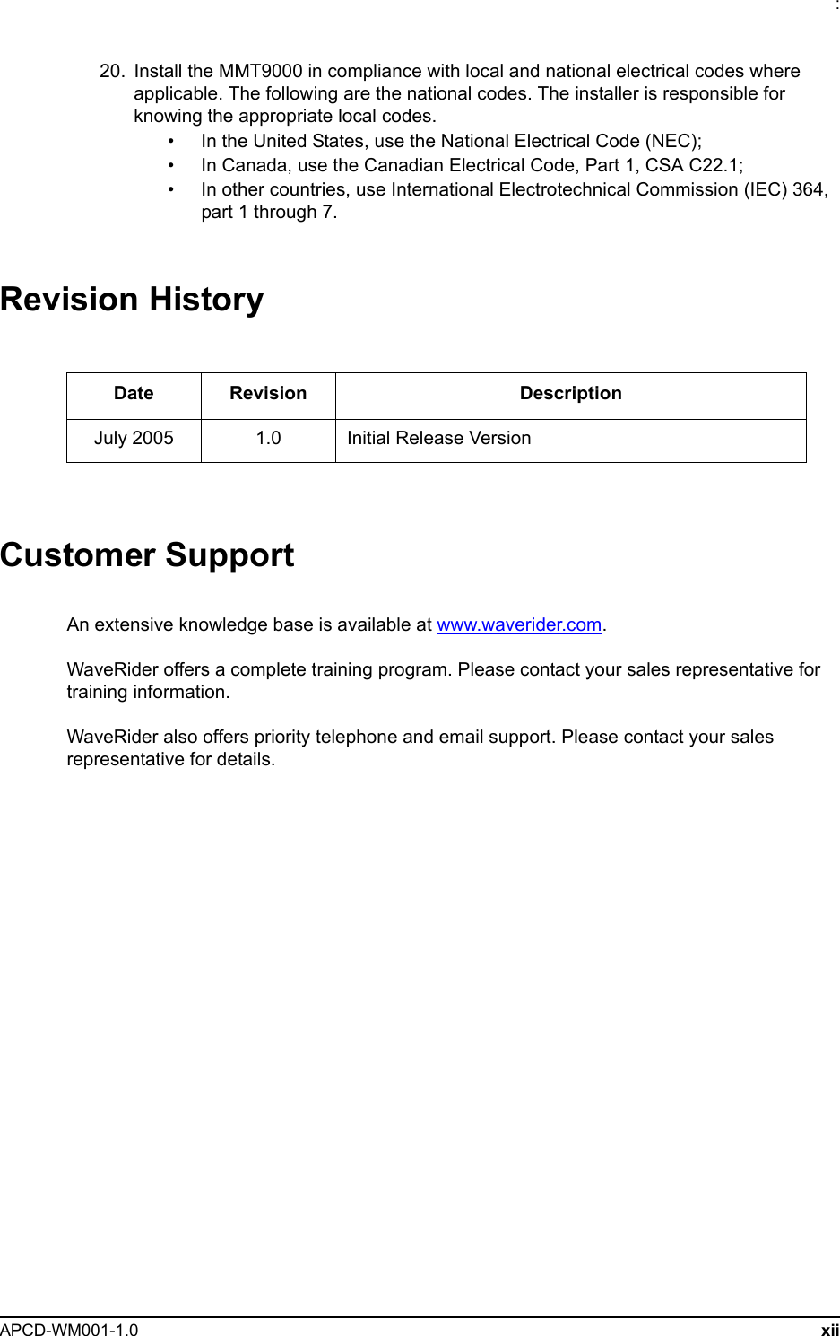
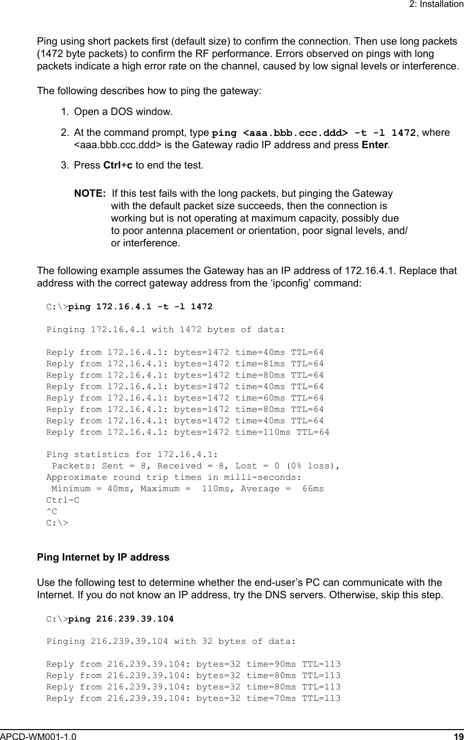
![2: InstallationAPCD-WM001-1.0 20Ping statistics for 216.239.39.104: Packets: Sent = 4, Received = 4, Lost = 0 (0% loss),Approximate round trip times in milli-seconds: Minimum = 70ms, Maximum = 90ms, Average = 80msPing Internet by NameUse the following test to verify that the DNS server IP address is correctly configured in the end-user’s PC and is operating properly:C:\> ping www.google.comPinging www.google.akadns.net [216.239.39.104] with 32 bytes of data:Reply from 216.239.39.104: bytes=32 time=72ms TTL=241Reply from 216.239.39.104: bytes=32 time=69ms TTL=241Reply from 216.239.39.104: bytes=32 time=76ms TTL=241Reply from 216.239.39.104: bytes=32 time=68ms TTL=241Ping statistics for 216.239.39.104: Packets: Sent = 4, Received = 4, Lost = 0 (0% loss),Approximate round trip times in milli-seconds: Minimum = 68ms, Maximum = 76ms, Average = 71ms2.4 Post-InstallationOnce a good link between the Base Station and the MMT9000 has been established, the configuration can be completed automatically using the Automatic Remote Configuration feature with a RADIUS Server and database in which the MMT9000 information has been entered. To use this feature, the network operator must update the RADIUS database for the new modem. This can be done before the modem is installed, in which case the modem will be automatically configured as soon as it has established a link. The configurable items that can be included in the Automatic Remote Configuration include:• password, • all SNMP parameters, • RF Frequency (including enabling Nomadic Base Station Discovery)• number of customers.If the Automatic Remote Configuration feature is not used, then the network operator can connect to the MMT9000 over the air and complete the configuration.Details on configuring a RADIUS Server or manually configuring an individual MMT9000s are covered in the LMS4000 Managing the Network manual or other manuals, available on the WaveRider web-site.](https://usermanual.wiki/Vecima-Networks/MMT9000/User-Guide-570844-Page-32.png)
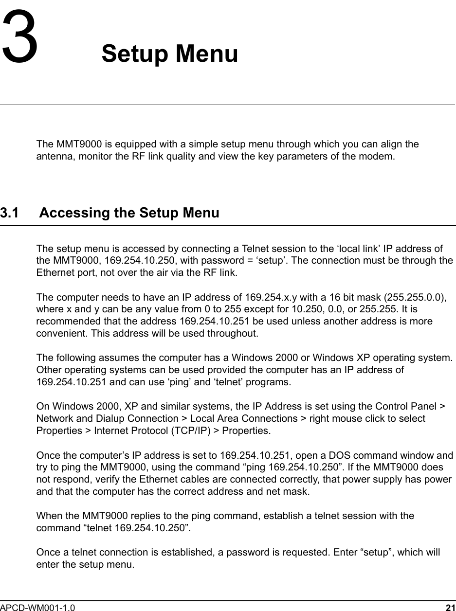
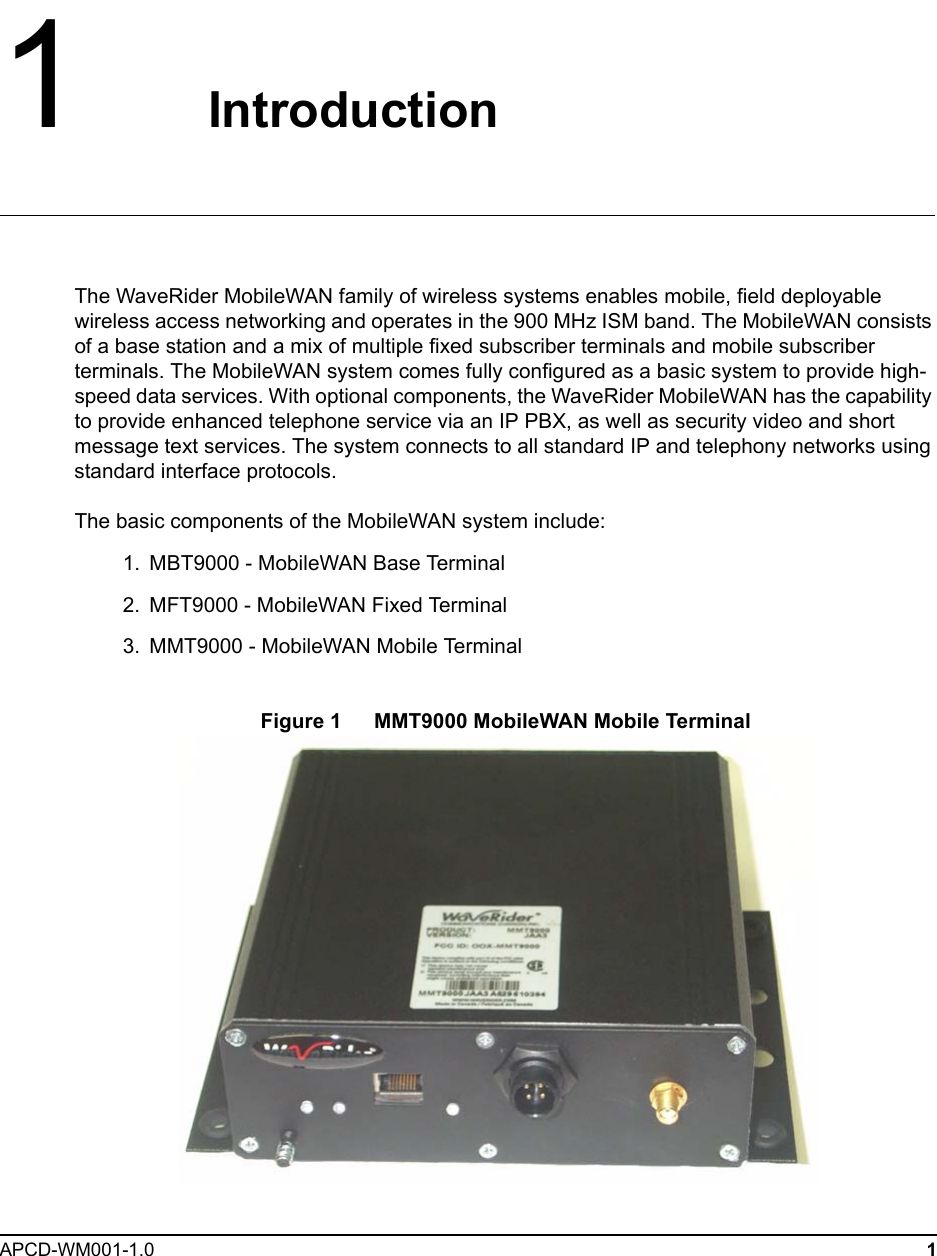
![3: Setup MenuAPCD-WM001-1.0 25The troubleshooting information display is shown below.Troubleshooting information Display MMT9000 Diagnostic Information----------------- MAC Summary ---------------------------------Transmitted Payloads 1Ok : 35 100.0% 2Ok : 0 0.0% 3Ok : 0 0.0% 4Ok : 0 0.0% Fail Retry : 0 0.0% Fail Timeout : 1Received Packets HCRC Error : 23993 3.0% Directed : 6948 0.8% Broadcast : 11178 1.4% No Match : 753093 94.7%Received Packets with Payloads FCS Error : 0 0.0% Duplicate : 0 0.0% Too Busy - Discard : 0 0.0% Delivered : 73 100.0%-------------------- IP Summary --------------------MMT9000 configuration Host Name . . . . . . . . . . . . : eum61-01-38 Physical Address. . . . . . . . . : 00:90:c8:61:01:38 IP Address. . . . . . . . . . . . : 207.54.100.172 Subnet Mask . . . . . . . . . . . : 255.255.255.240 Default Gateway . . . . . . . . . : 207.54.100.166 DHCP Server . . . . . . . . . . . : 207.54.100.166 Lease Obtained. . . . . . . . . . : 22-Jul-2005 22:58:36 Lease Expires . . . . . . . . . . : 23-Jul-2005 22:58:35------------------- Radio Summary ------------------RF Power: 26 dBmNomadic Mode - Locked on 60:0a:e0 at frequency 9114Using default search list (all frequencies).Printing non-zero frequencies onlyFrequency RSS FOM SQ FOM 9050 7.0 3.3 9086 7.0 2.3 9114 8.0 2.7 RSSI[dBm] RX; TX; R1; R2; R3; F;Retry%; SQ; RNA; RNBRSSI: -73 18; 0; 0; 0; 0; 0; 0; 8; 23; 23](https://usermanual.wiki/Vecima-Networks/MMT9000/User-Guide-570844-Page-37.png)