Vecima Networks MMT9000 Mobile Wan Vehicle Radio User Manual EUM3005 User Guide
Vecima Networks Inc. Mobile Wan Vehicle Radio EUM3005 User Guide
Manual

MMT9000
Installation Guide
APCD-WM001-1.0

:
APCD-WM001-1.0 ii
Copyright
© 2005 by WaveRider Communications Inc. You
may copy and/or print as many copies of this manual
as you wish, as long as the software license
agreement and this copyright statement are included.
Vers. 1.0, July 2005
The following are trademarks or registered trademarks of their respective companies or organi-
zations:
Windows XP/Microsoft
Windows 2000/Microsoft

:
APCD-WM001-1.0 iii
Software License Agreement
This is a legal agreement between you (either an individual or an entity) and WaveRider Communica-
tions Inc. for the use of WaveRider computer software, hereinafter the “LICENSED SOFTWARE”.
By using the LICENSED SOFTWARE installed in this product, you acknowledge that you have
read this license agreement, understand it, and agree to be bound by its terms. You further
agree that it is the full and complete agreement between you and WaveRider Communications
Inc., superseding all prior written or verbal agreements of any kind related to the LICENSED
SOFTWARE. If you do not understand or do not agree to the terms of this agreement, you will
cease using the LICENSED SOFTWARE immediately.
1. GRANT OF LICENSE—This License Agreement permits you to use one copy of the LICENSED
SOFTWARE.
2. COPYRIGHT—The LICENSED SOFTWARE is owned by WaveRider Communications Inc. and
is protected by copyright laws and international treaty provisions; therefore, you must treat the
LICENSED SOFTWARE like any other copyrighted material (e.g., a book or magazine).
3. LIMITS OF FEATURE AVAILABILITY—The LICENSED SOFTWARE is sold with limitations as
to certain feature availability and use. These limits are governed by the terms of the purchase
agreement. Any actions resulting in the exceeding of these limits is not permitted, and can result
in unpredictable performance.
4. OTHER RESTRICTIONS—You may not rent or lease the LICENSED SOFTWARE. You
may not reverse engineer, decompile, or disassemble the LICENSED SOFTWARE.
5. LIMITED WARRANTY—The LICENSED SOFTWARE is provided “as is” without any warranty of
any kind, either expressed or implied, including, but not limited to, the implied warranties of
merchantability and fitness for a particular purpose. The entire risk as to the quality and
performance of the LICENSED SOFTWARE is with you, the licensee. If the LICENSED
SOFTWARE is defective, you assume the risk and liability for the entire cost of all necessary
repair, service, or correction.
Some states/jurisdictions do not allow the exclusion of implied warranties, so the
above exclusion may not apply to you. This warranty gives you specific legal
rights, and you may have other rights, which vary from state/jurisdiction to state/
jurisdiction.
WaveRider Communications Inc. does not warrant that the functions contained in
the LICENSED SOFTWARE will meet your requirements, or that the operation of
the LICENSED SOFTWARE will be error-free or uninterrupted.
6. NO OTHER WARRANTIES—To the maximum extent permitted by applicable law, WaveRider
Communications Inc. disclaims all other warranties, either express or implied, including, but not
limited to, the implied warranties of merchantability and fitness for a particular purpose, with
regard to the LICENSED SOFTWARE and the accompanying written materials.
7. NO LIABILITY FOR CONSEQUENTIAL DAMAGES—To the maximum extent permitted by
applicable law, in no event shall WaveRider Communications Inc. or its suppliers be liable
for any damages whatsoever (including, without limitation, damages for loss of business
profits, business interruption, loss of business information, or any other pecuniary loss)
arising from the use of or inability to use the LICENSED SOFTWARE, even if WaveRider
Communications Inc. has been advised of the possibility of such damages, or for any claim
by any other party.
Because some states/jurisdictions do not allow the exclusion or limitation of liability for
consequential or incidental damages, the above limitation may not apply to you. In no event will
WaveRider’s liability exceed the amount paid for the LICENSED SOFTWARE.

:
APCD-WM001-1.0 iv
Warranty
In the following warranty text, “WaveRider®” shall mean WaveRider Communications Inc.
This WaveRider product is warranted against defects in material and workmanship for a period
of one (1) year from the date of purchase. During this warranty period WaveRider will, at its
option, either repair or replace products that prove to be defective.
For warranty service or repair, the product must be returned to a service facility designated by
WaveRider. Authorization to return products must be obtained prior to shipment. The WaveR-
ider RMA number must be on the shipping documentation so that the service facility will accept
the product. The buyer shall pay all shipping charges to WaveRider and WaveRider shall pay
shipping charges to return the product to the buyer within Canada or the USA. For all other
countries, the buyer shall pay shipping charges as well as duties and taxes incurred in shipping
products to or from WaveRider.
WaveRider warrants that the firmware designed by it for use with the unit will execute its pro-
gramming instructions when properly installed on the unit. WaveRider does not warrant that the
operation of the unit or firmware will be uninterrupted or error-free.
Limitation of Warranty
The foregoing warranty shall not apply to defects resulting from improper or inadequate mainte-
nance by the buyer, buyer-supplied interfacing, unauthorized modification or misuse, operation
outside the environmental specifications for the product, or improper site preparation or mainte-
nance. No other warranty is expressed or implied. WaveRider specifically disclaims the implied
warranties of merchantability and fitness for any particular purpose.
No Liability for Consequential Damages
To the maximum extent permitted by applicable law, in no event shall WaveRider or its suppli-
ers be liable for any damages whatsoever (including, without limitation, damages for loss of
business profits, business interruption, loss of business information, or any other pecuniary
loss) arising from the use of or inability to use the product, even if WaveRider has been advised
of the possibility of such damages, or for any claim by any other party.
Because some states/jurisdictions do not allow the exclusion or limitation of liability for conse-
quential or incidental damages, the above limitation may not apply to you.
In no event will WaveRider’s liability exceed the amount paid for the product.
Regulatory Notices
This equipment has been tested and found to comply with the limits for a Class B Intentional
Radiator, pursuant to Part 15 of the FCC Regulations. These limits are intended to provide pro-
tection against harmful interference when the equipment is operated in a residential environ-
ment.
This equipment generates, uses, and can radiate radio frequency energy and, if not installed
and used in accordance with the instruction manual, may cause harmful interference to radio
communications. However, there is no guarantee that interference will not occur in a particular
installation.
Notice to User
Any changes or modifications to equipment that are not expressly approved by WaveRider may
void the user’s authority to operate the equipment.

APCD-WM001-1.0 v
Contents
Figures . . . . . . . . . . . . . . . . . . . . . . . . . . . . . . . . . . . . . . . . . . . . . . . . . . . . . . . . . . . . . . . . . . vi
Tables . . . . . . . . . . . . . . . . . . . . . . . . . . . . . . . . . . . . . . . . . . . . . . . . . . . . . . . . . . . . . . . . . . vii
Preface . . . . . . . . . . . . . . . . . . . . . . . . . . . . . . . . . . . . . . . . . . . . . . . . . . . . . . . . . . . . . . . . .viii
1 Introduction . . . . . . . . . . . . . . . . . . . . . . . . . . . . . . . . . . . . . . . . . . . . . . . . . . . . . . . . . . . . 1
1.1 MMT9000 Features. . . . . . . . . . . . . . . . . . . . . . . . . . . . . . . . . . . . . . . . . . . . . . . . . . . . 2
1.2 Document Scope . . . . . . . . . . . . . . . . . . . . . . . . . . . . . . . . . . . . . . . . . . . . . . . . . . . . . 3
1.3 MMT9000 - MobileWAN Mobile Terminal . . . . . . . . . . . . . . . . . . . . . . . . . . . . . . . . . . . 4
1.3.1 MMT9000 Modem - External Indicators and Connectors . . . . . . . . . . . . . . . . . 5
1.3.2 MMT9000 Suite of Antennas . . . . . . . . . . . . . . . . . . . . . . . . . . . . . . . . . . . . . . . 7
1.3.3 MMT9000 Nomadic Operation . . . . . . . . . . . . . . . . . . . . . . . . . . . . . . . . . . . . . 9
2 Installation . . . . . . . . . . . . . . . . . . . . . . . . . . . . . . . . . . . . . . . . . . . . . . . . . . . . . . . . . . . . 10
2.1 Installation Checklist . . . . . . . . . . . . . . . . . . . . . . . . . . . . . . . . . . . . . . . . . . . . . . . . . . 10
2.2 Pre-Installation Steps . . . . . . . . . . . . . . . . . . . . . . . . . . . . . . . . . . . . . . . . . . . . . . . . . 11
2.2.1 Network and MMT9000 Configuration . . . . . . . . . . . . . . . . . . . . . . . . . . . . . . 11
2.2.2 Verifying the MMT9000 Components . . . . . . . . . . . . . . . . . . . . . . . . . . . . . . . 12
2.2.3 End-Users PC . . . . . . . . . . . . . . . . . . . . . . . . . . . . . . . . . . . . . . . . . . . . . . . . . 12
2.3 Installation Steps. . . . . . . . . . . . . . . . . . . . . . . . . . . . . . . . . . . . . . . . . . . . . . . . . . . . . 13
2.3.1 Locating the MMT9000 . . . . . . . . . . . . . . . . . . . . . . . . . . . . . . . . . . . . . . . . . . 13
2.3.2 Connecting to Vehicle Power System . . . . . . . . . . . . . . . . . . . . . . . . . . . . . . . 14
2.3.3 Connecting the End-User’s PC . . . . . . . . . . . . . . . . . . . . . . . . . . . . . . . . . . . . 14
2.3.4 Locating the MMT9000 Antenna . . . . . . . . . . . . . . . . . . . . . . . . . . . . . . . . . . . 15
2.3.5 Testing the Data Link . . . . . . . . . . . . . . . . . . . . . . . . . . . . . . . . . . . . . . . . . . . 16
2.4 Post-Installation . . . . . . . . . . . . . . . . . . . . . . . . . . . . . . . . . . . . . . . . . . . . . . . . . . . . . 20
3 Setup Menu . . . . . . . . . . . . . . . . . . . . . . . . . . . . . . . . . . . . . . . . . . . . . . . . . . . . . . . . . . . . 21
3.1 Accessing the Setup Menu . . . . . . . . . . . . . . . . . . . . . . . . . . . . . . . . . . . . . . . . . . . . . 21
3.2 Setup Menu. . . . . . . . . . . . . . . . . . . . . . . . . . . . . . . . . . . . . . . . . . . . . . . . . . . . . . . . . 22
3.3 Radio Link Status Display . . . . . . . . . . . . . . . . . . . . . . . . . . . . . . . . . . . . . . . . . . . . . . 22
3.4 Troubleshooting Information Display . . . . . . . . . . . . . . . . . . . . . . . . . . . . . . . . . . . . . 24
Appendix A Factory Configuration . . . . . . . . . . . . . . . . . . . . . . . . . . . . . . . . . . . . . . . . 27
Appendix B Ethernet Cables and Connectors . . . . . . . . . . . . . . . . . . . . . . . . . . . . . . 29

APCD-WM001-1.0 vi
Figures
Figure 1 MMT9000 MobileWAN Mobile Terminal . . . . . . . . . . . . . . . . . . . . . . . . . . . . 1
Figure 2 MMT9000 Components . . . . . . . . . . . . . . . . . . . . . . . . . . . . . . . . . . . . . . . . . 5
Figure 3 MMT9000 Modem - External Indicators and Connectors . . . . . . . . . . . . . . . 6
Figure 4 MMT9000 Suite of Antennas . . . . . . . . . . . . . . . . . . . . . . . . . . . . . . . . . . . . . 8
Figure 5 Possible Locations for MMT9000 . . . . . . . . . . . . . . . . . . . . . . . . . . . . . . . . 13
Figure 6 Possible Locations for MMT9000 Mobile Antenna . . . . . . . . . . . . . . . . . . . 15
Figure 7 T568A Wiring . . . . . . . . . . . . . . . . . . . . . . . . . . . . . . . . . . . . . . . . . . . . . . . 31
Figure 8 T568B Wiring . . . . . . . . . . . . . . . . . . . . . . . . . . . . . . . . . . . . . . . . . . . . . . . 31

APCD-WM001-1.0 vii
Tables
Table 1 Ethernet Status LEDs . . . . . . . . . . . . . . . . . . . . . . . . . . . . . . . . . . . . . . . . . . 6
Table 2 Signal Level LED Status . . . . . . . . . . . . . . . . . . . . . . . . . . . . . . . . . . . . . . . . 6
Table 3 MMT9000 Mobile Antennas . . . . . . . . . . . . . . . . . . . . . . . . . . . . . . . . . . . . . 7
Table 4 MT9000 Mobile Antenna Mounts . . . . . . . . . . . . . . . . . . . . . . . . . . . . . . . . . 8
Table 5 Pre-Installation Stage Checklist . . . . . . . . . . . . . . . . . . . . . . . . . . . . . . . . . 10
Table 6 Installation Stage Checklist . . . . . . . . . . . . . . . . . . . . . . . . . . . . . . . . . . . . . 11
Table 7 MMT9000 Wiring to Vehicle Power System . . . . . . . . . . . . . . . . . . . . . . . . 14
Table 8 Signal Strength Figure of Merit . . . . . . . . . . . . . . . . . . . . . . . . . . . . . . . . . . 24
Table 9 Signal Quality Figure of Merit . . . . . . . . . . . . . . . . . . . . . . . . . . . . . . . . . . . 24
Table 10 Ethernet Interface Specifications . . . . . . . . . . . . . . . . . . . . . . . . . . . . . . . . 30
Table 11 Wiring T568A and T568B ends for Ethernet Cables . . . . . . . . . . . . . . . . . . 30
:
APCD-WM001-1.0 viii
Preface
Conventions
The following conventions are used throughout this document:
WARNING!
Whenever you see this icon and heading, the associated text
addresses or discusses a critical safety or regulatory issue.
CAUTION: Whenever you see this icon and heading, the
associated text discusses an issue, which, if not followed, could
result in damage to, or improper use of, the equipment or
software.
TIP: Whenever you see this icon and heading, the associated
text provides a tip for facilitating the installation, testing, or
operation of the equipment or software.
Regulatory Notices
This device has been designed to operate with only the antenna types listed in this manual.
This device has been tested using unshielded Ethernet CAT-5 cable.
There can be no modications made to the MMT9000 or its antennas without the express
permission of WaveRider. Failure to comply may void the user’s authority to operate this
equipment in accordance with FCC regulations.
Federal Communications Commission
The MMT9000 has been designed and manufactured to comply with FCC Part 15.
Operators must be familiar with the requirements of the FCC Part 15 Regulations prior
to operating any link using this equipment. For installations outside the United States,
contact local authorities for applicable regulations.
The FCC ID for the MMT9000 equipment is OOX-MMT9000.
The transmitter of this device complies with Part 15.247 of the FCC Rules.

:
APCD-WM001-1.0 ix
Note: This equipment has been tested and found to comply with the limits for a Class
B digital device, pursuant to part 15 of the FCC Rules. These limits are designed to
provide reasonable protection against harmful interference in a residential installation.
This equipment generates, uses and can radiate radio frequency energy and, if not
installed and used in accordance with the instructions, may cause harmful
interference to radio communications. However, there is no guarantee that
interference will not occur in a particular installation. If this equipment does cause
harmful interference to radio or television reception, which can be determined by
turning the equipment off and on, the user is encouraged to try to correct the
interference by one or more of the following measures:
• Reorient or relocate the receiving antenna.
• Increase the separation between the equipment and receiver.
• Connect the equipment into an outlet on a circuit different from that to which the
receiver is connected.
• Consult the dealer or an experienced radio/TV technician for help.
Interference Environment
Operation is subject to the following conditions:
• This device may not cause harmful interference and,
• This device must accept any interference received, including interference that
might cause undesired operation.
Operational Requirements
In accordance with the FCC Part 15 regulations:
1. The maximum average power output of the intentional radiator shall not
exceed one (1) watt (30 dBm) for all spread spectrum systems operating in
the 902 to 928MHz band.
2. Stations operating in the 902 to 928MHz band may use transmitting antennas
of directional gain greater than 6dBi, provided the average output power from
the intentional radiator is reduced by the amount in dB that the directional gain
of the antenna exceeds 6dBi.
3. The operator of a spread spectrum system and the user of the radio device
are each responsible for ensuring that the system is operated in the manner
outlined in Interference Environment on page ix.
The MMT9000 with its certified antenna complies with these requirements.
Warnings and Advisories
General Advisory
Installers, operators and maintenance personnel must be familiar with the related safety
requirements before they attempt to install or operate the MMT9000.

:
APCD-WM001-1.0 x
It is the responsibility of the operator to ensure that the public is not exposed to excessive
Radio Frequency (RF) levels. The applicable regulations can be obtained from local
authorities.
WARNING!
To comply with FCC RF exposure limits, the MMT9000 mobile
antennas must be mounted to provide a separation distance
of 20cm (8 inches) or more from all persons. The MMT9000
panel antenna must be mounted to provide a separation
distance of 30cm (12 inches) or more from all persons. The
distance is measured from the nearest point of the antenna to
the human body.
WARNING!
The MMT9000 is only to be installed by qualified professional
installers, who are familiar FCC regulations and with
installing radio transmission equipment, especially in
vehicles. The installer must be familiar with all installation
procedures and restrictions contained herein.
Important Safeguards
WARNING!
CAUTION: To reduce risk of electrical shock, do not remove
covers, since there are no user-serviceable parts inside.
Refer servicing to qualified personnel.
1. Read all these instructions before installing and operating the MMT9000.
2. Retain these instructions for future reference.
3. Heed all warnings on the MMT9000 and in these instructions.
4. Follow all instructions.
5. Disconnect MMT9000 from its power source before cleaning. Clean only with a damp
cloth.
6. Use only attachments recommended by WaveRider.
7. The metal housing protects the MMT9000 from overheating to ensure reliable
operations. Do not cover the MMT9000. Although the MMT9000 has been rated for a
wide range of temperatures, it will perform better and longer if proper ventilation is
provided.

:
APCD-WM001-1.0 xi
8. Operate the MMT9000 only from a 13.8 VDC (+-/25%) power supply, such as a
standard vehicle power system. Using other voltages, such as 24 VDC or AC power,
can result in damage to the MMT9000.
9. Use the fuse assembly provided to protect the MMT9000 from power surges in the
vehicle power system as well as protecting the power system from short circuits in the
MMT9000 or its power cable.
10. Route the Power-supply cable, Ethernet cable and Antenna cable so that they are not
likely to be walked on or pinched by items placed upon or against them, paying
particular attention to cord and cables at their plugs, convenience receptacles and the
points where the cords exit the equipment.
11. Provide strain relief for cables near their connections. This is typically done by leaving
a loop in the cable near the connection.
12. Do not locate the MMT9000 in the vicinity of power lines or other electric light or power
circuits, or where it can fall onto such power lines or circuits.
13. For added protection during a lightning storm, or when it is left unattended and unused
for long periods of time, unplug the MMT9000. This will power down the MMT9000.
14. Never push foreign objects of any kind through openings (e.g. Ethernet jack) in this
wireless product as they may short-out parts that could result in a fire or electric shock
and damage the unit.
15. The MMT9000 is a rugged unit that can tolerate a wide range of environments if
installed correctly, but it is not rated as being submersible nor immune to all liquids
from all directions. If the MMT9000 may experience rain, then mount the unit so that
the rain does not fall on or drip directly onto the connector endplate.
16. Do not attempt to service this wireless product yourself. Refer all servicing to qualified
service personnel.
17. Unplug the unit and refer servicing to qualified service personnel under the following
conditions:
• When the power supply cord or plug is damaged.
• If the MMT9000 does not operate normally for an extended period of time when
following the operating instructions. Note that it is possible that Internet traffic can
be slow even under normal operations due to network congestion and radio
interference and fading and not as result of problems with the MMT9000.
• When the MMT9000 exhibits distinct changes in performance. This may indicate a
need for service.
18. When replacement parts are required, be sure the service technician has used
replacement parts specified by WaveRider or with the same characteristics as the
original part. Improper substitutions may result in fire, electric shock or other hazards.
19. Upon completion of any service or repairs to this wireless product, ask the service
technician to perform safety checks to determine that the wireless product is in proper
operating condition.

:
APCD-WM001-1.0 xii
20. Install the MMT9000 in compliance with local and national electrical codes where
applicable. The following are the national codes. The installer is responsible for
knowing the appropriate local codes.
• In the United States, use the National Electrical Code (NEC);
• In Canada, use the Canadian Electrical Code, Part 1, CSA C22.1;
• In other countries, use International Electrotechnical Commission (IEC) 364,
part 1 through 7.
Revision History
Customer Support
An extensive knowledge base is available at www.waverider.com.
WaveRider offers a complete training program. Please contact your sales representative for
training information.
WaveRider also offers priority telephone and email support. Please contact your sales
representative for details.
Date Revision Description
July 2005 1.0 Initial Release Version
APCD-WM001-1.0 1
1 Introduction
The WaveRider MobileWAN family of wireless systems enables mobile, field deployable
wireless access networking and operates in the 900 MHz ISM band. The MobileWAN consists
of a base station and a mix of multiple fixed subscriber terminals and mobile subscriber
terminals. The MobileWAN system comes fully configured as a basic system to provide high-
speed data services. With optional components, the WaveRider MobileWAN has the capability
to provide enhanced telephone service via an IP PBX, as well as security video and short
message text services. The system connects to all standard IP and telephony networks using
standard interface protocols.
The basic components of the MobileWAN system include:
1. MBT9000 - MobileWAN Base Terminal
2. MFT9000 - MobileWAN Fixed Terminal
3. MMT9000 - MobileWAN Mobile Terminal
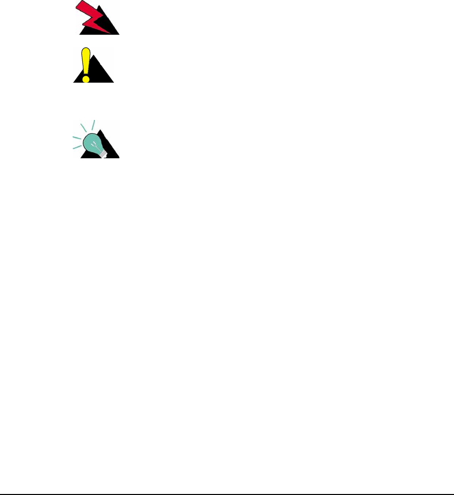
Figure 1 MMT9000 MobileWAN Mobile Terminal

1: Introduction
APCD-WM001-1.0 2
The MMT9000 is the first component of the MobileWAN family to be released. The MMT9000
is a rugged vehicle data-radio that provides Ethernet access to the IP-based internet. The
MMT9000 has been designed to be easily installed into a vehicle and be powered from a
vehicle's 12 VDC1 power system.
1.1 MMT9000 Features
The MMT9000 is well suited for mobile applications in the following industries:
• remote works sites,
• private communications networks,
• municipal governments,
• public works,
• large construction projects,
• homeland security,
• public safety (non life threatening),
• industrial solutions, and
• special events.
The MMT9000 is capable of delivering high-speed data, voice, and video. It can work with
VPNs and other security middle ware.
The MMT9000 is a mobile wireless modem that connects to the user's computer through an
Ethernet connection. It is intended to be installed in a vehicle and provides an interface to the
customer's computer or local area network on one side and wireless access to the LMS4000
network on the other.
The MMT9000, which acts as a network bridge, receives data from the Base Station
(MBT9000, CCU3000 or NCL1900)2 over the 900 MHz radio link, and forwards this data to the
user's computer through the Ethernet port. In the other direction, the MMT9000 forwards data
received from the user's computer over the radio link to the Base Station.
The MMT9000 has a compact form factor designed for use in a vehicle, including emergency
vehicles. The MMT9000 has outstanding RF performance in a hostile mobile environment.
Temperature, vibration, shock, exposure to moisture and ease of installation have all been
considered in the modem packaging. Set-up and configuration is rapid and simple.
1. We refer to the MMT9000 as being powered by 12 VDC. This is by convention and
refers to the 12 VDC power system on most vehicles. The actual input power
specification is 13.8 VDC +/- 25%.
2. We will use the generic term “Base Station” throughout this document to stand for any of
the WaveRider 900 MHz base station products, the CCU3000, NCL1900 or MBT9000

1: Introduction
APCD-WM001-1.0 3
Features of the MMT9000 include:
•Nomadic Base Station Discovery (factory default) - The MMT9000 searches all
available channels or channels from a user-defined list. The MMT9000 selects which
Base Station or access point to establish a connection based on airlink quality and
authorization acceptance. With this and DCHP Client enabled (factory defaults), the
installer does not need to enter ANY configuration parameters into the MMT9000 in
order to install it.
•DHCP Client (factory default)- The MMT9000 can obtain its IP address, subnet mask
and IP gateway information from a DHCP server, reducing the amount of
configuration required for installation. This allows the network operator to reassign IP
addresses to MMT9000s without having to access the mobile terminal itself.
•Auto Remote Configuration - The MMT9000 will accept parameters from a RADIUS
server to set other configurable parameters in the modem. These parameters include:
password, all SNMP parameters, RF Frequency (including enabling auto-discovery),
and number of hosts.
•Monitoring Tools - The MMT9000 has a Windows GUI, LEDs and a SETUP Menu to
make monitoring the airlink very accessible to the user. The MMT9000 supports the
local link IP address, 169.254.10.250, on its Ethernet port at all times. Using the local-
link address, the user can use the password “setup” at any time to call up the setup
menu that allows any user to check the RF link quality to verify connectivity.
•Mobile and Fixed Antennas - The MMT9000 is certified to work with a variety of
antennas, including whip antennas that can be permanently mounted on a vehicle or
magnetically mounted and a high-gain panel antenna that can be mounted on a
mobile command center or permanently installed as required.
•Interoperable with LMS4000 System - The MMT9000 can connect to the MBT9000,
CCU3000 or NCL1900 as Base Stations. It can also share the network with a mixture
of MMT9000s, MFT9000s, and residential EUMs. Thus the MMT9000 can use a
network designed exclusively for its use and/or existing LMS4000 networks.
Detailed specifications for the MMT9000 can be found on the WaveRider website.
1.2 Document Scope
This installation guide provides general guidelines for the installation and configuration of the
MMT9000, its performance, and any required regulatory information, including approved
installation notices. The Setup menu is described, which can be used to align the MMT9000
antennas.
The concepts for the MobileWAN family of components are the same as the fixed wireless
LMS4000 family. Related information can be found in the suite of available LMS4000
manuals, which includes the following:
•LMS4000 900 MHz Radio Networking Concepts (APCD-LM053)
•LMS4000 Data Networking Concepts (APCD-LM050)
•LMS4000 Managing the Network (APCD-LM052)
•LMS4000 CLI Reference Manual (APCD-LM051)

1: Introduction
APCD-WM001-1.0 4
•LMS4000 SNMP Reference Manual (APCD-LM049)
• Acronyms and Glossary (APCD-LM056)
These manuals provide information not included in this Installation Guide, including
information on:
• Planning, installing and managing the network.
• Diagnostic tools for the network and modems.
• Details on the Command Line Interface and methods of accessing the modems.
• Manual configuration of the modem via the CLI.
• Glossary of network terms.
These manuals can be found on WaveRider’s Web site (http://www.waverider.com).
NOTE: The installer may be required to manually configure the
MMT9000. In this case, the installer should be familiar with
LMS4000 CLI Reference Manual (APCD-LM051).
Other documents on the WaveRider web site are useful to assist in installing and operating the
MMT9000.
WaveRider recommends that you be familiar with the following sections before proceeding
with the instructions in this guide:
•Software License Agreement on page iii
•Warranty on page iv
•Conventions on page viii
•Warnings and Advisories on page ix
•Important Safeguards on page x
NOTE: The information contained in this manual is subject to change
without notice. The reader should consult the WaveRider web
site for updates.
1.3 MMT9000 - MobileWAN Mobile Terminal
Figure 2 shows the components that make up the MMT9000 MobileWAN Mobile Terminal.
Key elements of the MMT9000 are described on the following pages:
•MMT9000 Modem - External Indicators and Connectors on page 5
•MMT9000 Suite of Antennas on page 7
•MMT9000 Nomadic Operation on page 9
1: Introduction
APCD-WM001-1.0 5
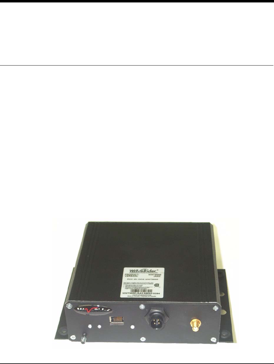
Figure 2 MMT9000 Components
1.3.1 MMT9000 Modem - External Indicators and Connectors
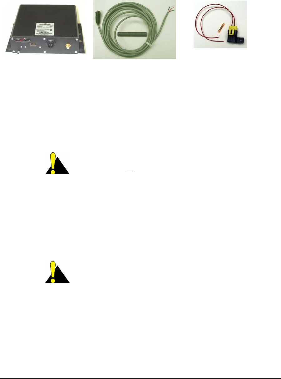
All interfaces on the MMT9000 are on one side of the radio for ease of installation. The
following interfaces are:
• Ethernet port - 10BaseT RJ45 receptacle to connect the modem to the end-user’s
computer. Details on the Ethernet port are found in Appendix B on page 29.
CAUTION: Any DC voltage applied to the Ethernet port may
damage the MMT9000, the Ethernet cable, and/or network gear.
The MMT9000 is not a Power-over-Ethernet device.
• SMA-F Antenna Port - for connecting one of the approved mobile or fixed antennas to
the MMT9000. See section 1.3.2, MMT9000 Suite of Antennas for details on the
antennas.
• DC Power Connector - a watertight, locking 4 pin receptacle receives the connector
from vehicle power system cable. The MMT9000 comes with an 18-ft. cable for
connecting to the vehicle power system as well as a fuse assembly. The pin out and
connection details are discussed in Connecting to Vehicle Power System on page 14.
CAUTION: Use standard vehicle power system (13.8 VDC +/-
25%) only. Any other voltage can result in damage to the modem.
• Chassis Ground Lug - this should be connected to the vehicle chassis or ground
system.
The MMT9000 also has 3 LEDs. Figure 3 shows the layout of the MMT9000 Connectors and
LEDs, while Table 1 and Table 2 explain what each LED means.
MMT9000 Modem Fuse Assembly12 VDC Power Cable
1: Introduction
APCD-WM001-1.0 6
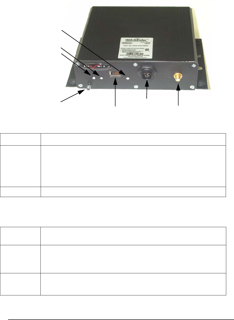
Figure 3 MMT9000 Modem - External Indicators and Connectors
Table 1 Ethernet Status LEDs
Table 2 Signal Level LED Status
Signal Level
Ethernet Link
Ethernet Socket
Power Connector
Antenna Connector
Ethernet Traffic
Ground Lug
LED State Ethernet Status
Ethernet Link If the Link LED is ON, the Ethernet physical connection is configured and working
properly. If the Link LED is OFF, then the Ethernet physical connection is not
working properly, which could be because the wrong type of cable was used or
there is a problem with the host or device Ethernet interface.
If connecting directly to the end-user PC, use the crossover Ethernet cable pro-
vided. If connecting to a router or switch, use a straight-through cable.
Ethernet Traffic The Ethernet Traffic LED flashes whenever the link is transferring data.
Signal Level
State Status
Flashing The MMT9000 has adequate signal level to support the radio link. As the signal
level increases, the flash rate increases. If possible, turn or move the antenna
slowly until the Signal Level LED flashes as fast as possible (i.e. turn panel
antenna, reposition magnetic mounted antennas).
Off The MMT9000 does not have adequate signal level (<-86 dBm). Move and/or
turn the antenna until it begins flashing. If a permanently mounted mobile
antenna is being used, then the vehicle needs to move.

1: Introduction
APCD-WM001-1.0 7
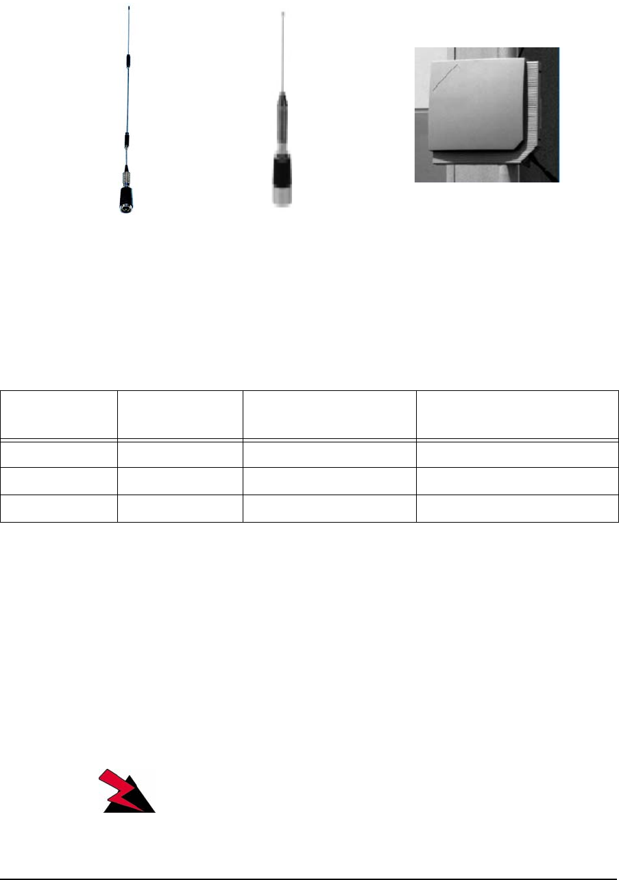
1.3.2 MMT9000 Suite of Antennas
Only the following antennas are approved by FCC to be used with the MMT9000. All of these
antennas and their mounting assemblies can be purchased from WaveRider.
The end user must position the antenna correctly to receive an adequate signal level.This is
especially true of the panel antenna which is a directional antenna. The Radio LED on the
MMT9000, described in section 1.3.1, MMT9000 Modem - External Indicators and
Connectors, or the Setup menu, described in Setup Menu on page 21, can be used to help
with the alignment..
WARNING!
To comply with FCC RF exposure limits, the MMT9000 mobile
antennas must be mounted to provide a separation distance
of 20cm (8 inches) or more from all persons. The MMT9000
panel antenna must be mounted to provide a separation
distance of 30cm (12 inches) or more from all persons. The
distance is measured from the nearest point of the antenna to
the human body.
MMT9000 Mobile Antennas
The MMT9000 is designed for use with variety of mobile whip antennas. The following mobile
antennas has been certified to be used with MMT9000:
Table 3 MMT9000 Mobile Antennas
NOTE: The mobile antennas must be mounted on a metal surface at
least 1 Meter diameter for best performance.
Maker Model Gain Mount
Pacific Wireless RFLMA9 7 dBi RFLMM-110
MAXRAD MUF9035NGP(S) 5 dBi BGMML or BMAML
MAXRAD MUF9025NGP(S) 5 dBi BGMML or BMAML
MAXRAD MUF9003NGP(S) 3 dBi BGMML or BMAML
MAXRAD MUF9035NGP(S) 3 dBi BGMML or BMAML
MAXRAD MUF9000NGP(S) Unity BGMML or BMAML
1: Introduction
APCD-WM001-1.0 8
Figure 4 MMT9000 Suite of Antennas
The following are the mounting options for these mobile antennas:
Table 4 MT9000 Mobile Antenna Mounts
*1 - Installer will need to replace existing connector with SMA-M connector to mate with
MMT9000.
MMT9000 Fixed Antenna
The MMT9000 has an FCC-approved, fixed outdoor panel antenna, the Maxrad Z1836. It is
provided with 25-ft. LMR200 RF cable. Since the panel antenna has a 65 degree beam width
and better than 17 dB front-to-back ratio, it can be positioned to suppress interference from
other wireless devices.
WARNING!
To comply with FCC RF exposure limits, the MMT9000 panel
antenna use at least 6 feet of LMR200 cable.
Pacific Wireless
RFLMA9
MAXRAD
MUF9035NGPS
MAXRAD
Z1836
Maker Model Type Cable Length / Type
Provided
Pacific Wireless RFLMM-110 RFLinx Magnetic Mount 10-ft. RG-58/U (*1)
MAXRAD BGMML Magnetic Mount 12-ft. LMR195
MAXRAD BMAML Permanent Mount 12-ft. LMR195

1: Introduction
APCD-WM001-1.0 9
1.3.3 MMT9000 Nomadic Operation
A key feature of the MMT9000 is its Nomadic Operations. This feature allows the MMT9000 to
quickly search for the best Base Station. Should the signal from theBase Station become too
poor, the MMT9000 re-searches for the next Base Station. In this way, the MMT9000 is never
out of touch with a Base Station for more than a few seconds, provided that it is moving
around within the coverage areas of several base stations.
To implement Nomadic Operations, the MMT9000 constantly monitors the signal from the
Base Station. When the packet error rate goes above 15% for 15 seconds, the MMT9000
searches through a list of frequencies and registers with the “best” Base Station that will allow
it to register.
The factory default is for the MMT9000 to search all 101 frequencies. To speed up the search,
a list of frequencies to be used can be configured to force the MMT9000 to search only the
relevant frequencies.
Care must be taken when designing an LMS network that will support nomadic units. If an
MMT9000 moves between two Base Station that support the same IP subnet (i.e. are in
switched mode on the same Ethernet broadcast domain) then service will continue nearly
uninterrupted. However, if an MMT9000 moves between two Base Station supporting
separate IP subnets (routed mode or separate domains), then the end-user’s PC(s) will have
to have new IP addresses, by DHCP or mobile IP protocols.
The “break-on-line” feature can assist in triggering the end-user PC to get a new IP address.
This feature disables the Ethernet port on the MMT9000 for a configurable period of time when
a search for a new base station frequency is started. Disabling the Ethernet port for long
enough forces most current operating systems on the user's computer to request a new IP
address, gateway and DNS servers via DHCP. For computers running Windows XP,
WaveRider recommends a 7 second break time. Use the command “rad freq nomadic 7” to set
the MMT9000 to nomadic mode with a 7 second break time.
The “break-on-line” feature only works if the PC is directly connected to the MMT9000
Ethernet port. If a hub or switch is placed between the PC and the MMT9000, the PC will not
lose its Ethernet link, since that is provided by the hub or switch.
If the MMT9000 itself has its DHCP client enabled, then it will use DHCP to get a new IP
address for the modem when it changes Base Stations.

APCD-WM001-1.0 10
2 Installation
The MMT9000 must be installed by a professional installer who is familiar with the FCC
regulations that apply to the MMT9000. Familiarity with installing vehicle-mounted 2-way radio
equipment is highly desirable. Best practices applicable to vehicle mounted radio systems
should be followed for providing power and grounding to the modem as well as antenna
placement on a vehicle.
2.1 Installation Checklist
A successful installation is divided into pre-installation, installation and post-installation stages,
with each stage outlined in the following checklists.
The Pre-Installation Stage Checklist involves the Network Operator as well as the installer.
Table 5 Pre-Installation Stage Checklist
When everything is ready for the installation stage, then the installer performs the following
steps:
Step Discussion
section 2.2.1, Network and
MMT9000 Configuration
The network must be properly configured by the
Network Operator to accept the new modem.
section 2.2.2, Verifying the
MMT9000 Components
Ensure that all the needed parts are included.
section 2.2.3, End-Users PC The end-user’s PC requires an Ethernet Network
Interface to accept the data from the MMT9000.

2: Installation
APCD-WM001-1.0 11
Table 6 Installation Stage Checklist
Once the installation is complete and verified, the network operator can complete the Post-
installation Stage, using the Automatic Remote Configuration feature or manually over the air.
This is discussed in section 2.4, Post-Installation
2.2 Pre-Installation Steps
2.2.1 Network and MMT9000 Configuration
There are a number of steps that must be undertaken by the network operator before installing
an MMT9000. For more information, see the LMS4000 Data Networking Concepts (APCD-
LM050), LMS4000 900 MHz Radio Networking Concepts (APCD-LM053), LMS4000
Managing the Network (APCD-LM052), and LMS4000 CLI Reference Manual (APCD-LM051)
on the WaveRider web-site.
1. Base Station Authorization: Ensure that the MMT9000 is authorized at one or more
Base Stations with the appropriate Grade of Service.
2. IP Addresses: Configure a DHCP server to accept the new MMT9000’s request(s) for
an IP address, if the modem has DHCP enabled (factory default). If not using DHCP,
then the MMT9000 must be manually configured with the following settings:
• IP address
• Subnet mask
• Gateway IP address
3. Frequency Assignment: If the Nomadic Base Station Discovery feature (factory
default) is used, then the MMT9000 will search for the Base Station upon power up.
Step Discussion
section 2.3.1, Locating the
MMT9000
For vehicle installation, the MMT9000 should be mounted
in an appropriate location. The MMT9000 is rugged
enough to be mounted in any partly protected location.
section 2.3.2, Connecting to
Vehicle Power System
The MMT9000 is powered from the vehicle’s 12 VDC
power system.
section 2.3.3, Connecting
the End-User’s PC
Connect the modem to the end-user’s PC.
section 2.3.4, Locating the
MMT9000 Antenna
The MMT9000 mobile antennas mount to vehicle roofs or
trunks. The external panel can be mounted on command
centers, trailers, etc. Find the best location for mounting
the MMT9000 antenna at least 20 cm away from where
people will stand.
section 2.3.5, Testing the
Data Link
Confirm that the link is functioning correctly.

2: Installation
APCD-WM001-1.0 12
This is the recommended approach. If for some reason this is not acceptable, then the
MMT9000 must be configured with its radio frequency.
The easiest installation uses the MMT9000 factory defaults, so that the modem will gets all its
IP address information from DHCP and its RF Frequency from the Nomadic Base Station
Discovery feature.
Other useful information for the installer includes:
• The IP address of a site that accepts pings as well as the name of a site that accepts
pings, for testing the data link.
• Whether modem is being connected directly to end-user PC or via an Ethernet switch
or IP router. In the latter cases, the installer must provide a straight-through Ethernet
cable to connect the modem to the switch/router.
2.2.2 Verifying the MMT9000 Components
See MMT9000 - MobileWAN Mobile Terminal on page 4 for more information on the MMT9000
kit. Verify that the MMT9000 kit is complete with:
• MMT9000 modem
• Power cable assembly
• Fuse assembly
In addition to the modem itself, verify that the antenna selected for the installation is complete,
including:
• Antenna
• Antenna Mounting hardware, be it a magnetic or vehicle mount for the mobile
antennas or clamping hardware for the panel antenna
Equipment that is needed but not provided since it will unique to each installation, includes:
• Ethernet cable - this will be a straight-through or cross-over cable depending on
whether the end-user’s PC is connected to a switch or directly to the MMT9000.
• Mounting bolts, washers and nuts - for attaching the MMT9000 rail to an equipment
tray, directly to the vehicle or to some other attachment point.
2.2.3 End-Users PC
Ensure that the end-user PC is equipped with an Ethernet interface.
2: Installation
APCD-WM001-1.0 13
2.3 Installation Steps
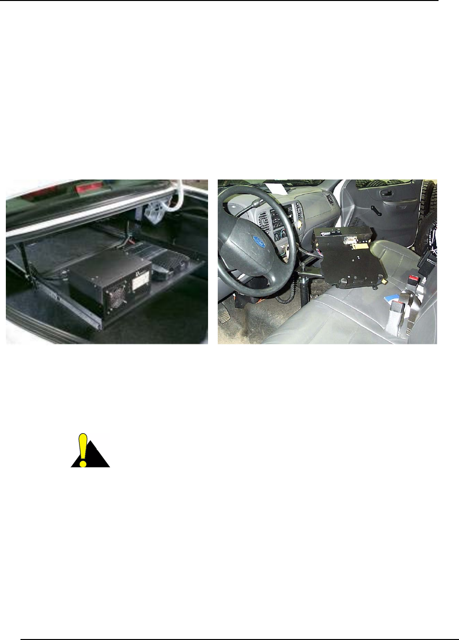
2.3.1 Locating the MMT9000
The MMT9000 has been designed and tested for a rugged mobile environment. It is designed
to meet IP53 rating (dust protected, light rain), so an additional enclosure to house the modem
is not required. The MMT9000 can be installed in the trunk area or in the passenger
compartment of the vehicle. Do not install in the engine compartment.
The location of the MMT9000 in a vehicle should be close as possible to the mobile antenna to
reduce cable insertion loss.
Figure 5 Possible Locations for MMT9000
Other possible locations for the MMT9000 are. under the driver or passenger seat, trunk side
panel or trunk floor
CAUTION: If the MMT9000 is likely to be exposed to rain or
spray, orient the MMT9000 so that the connector endplate is more
protected.This can be achieved by having the connectors facing
down or facing away from the exposed side. All connectors except
the Ethernet connector are waterproof. If the Ethernet connector is subjected
to too much spray, it can leak and/or short out until dry. Ensure the boot of the
Ethernet cable is snug against the chassis.
Trunk Shelf Console Floor

2: Installation
APCD-WM001-1.0 14
2.3.2 Connecting to Vehicle Power System
The MMT9000 is designed to work directly from the vehicle +12VDC electrical system or from
a +12VDC power distribution panel.
Included in the MMT9000 kit is an 18-ft., 4-wire, 18-gauge cable with an 2-amp inline fuse kit
(see Figure 2 on page 5). The connector to the modem is a twist-lock assembly. The following
table shows the wire color and its purpose:
The MMT9000 also has a ground lug on the connector endplate which should be connected to
the vehicle ground system.
The MMT9000 can be installed in other locations than just a vehicle, so long as the input
power is 13.8 VDC +/- 25% and there is a ground system.
2.3.3 Connecting the End-User’s PC
The Ethernet interface on the MMT9000 is a 10BaseT Ethernet RJ-45 receptacle. If
connecting directly to the end-user’s PC, a crossover cable is required. If connecting to an
Ethernet hub or switch, a straight-through Ethernet cable is used.
The Ethernet cable must be able to withstand the same environment as the MMT9000, so
cable rated as CAT5 outdoor or better is recommended
An Ethernet surge suppressor should be connected as close as possible to the MMT9000
Ethernet interface. This suppressor must be connected to the chassis ground.
As noted, there are many ways to connect the MMT9000 to the end-user’s PC, using Ethernet
switches, IP routers, etc. The discussion below is for the simplest, most direct method of
connection.
1. Connect the end-user’s PC by attaching a crossover Ethernet cable between the
Ethernet port on the end-user’s computer and the Ethernet port on the modem.
2. Apply power and wait 10 seconds for the MMT9000 to come up.
3. Check the Ethernet LEDs on the Ethernet interface of the modem and/or end-user’s
PC to ensure the Ethernet connection between the MMT9000 and the end-user’s PC
is active. Refer to Table 1 on page 6 for an explanation of the Ethernet LEDs normally
provided on Ethernet interface cards.
Table 7 MMT9000 Wiring to Vehicle Power System
Wire Color Description
Black 0 VDC (Battery Negative side)
Red +12 VDC
White Ignition Sense: +12VDC turns unit on. Tie to
Red if not using ignition sensing
Green Chassis ground, same ground as antenna
base.
2: Installation
APCD-WM001-1.0 15
4. When attempting to send data to, or receive data from, the Internet, check the
Ethernet Traffic LED to ensure data transmission is taking place. This LED flashes as
data traffic passes between the end-user’s PC and the MMT9000
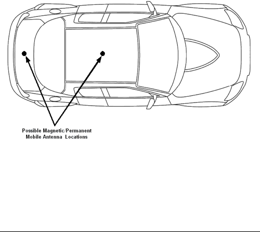
2.3.4 Locating the MMT9000 Antenna
Mobile Antenna
The mobile antennas for the MMT9000 should be mounted on the top of the vehicle or in the
middle of the trunk lid. These locations provide good unobstructed locations that are at least
20 cm away from people. WaveRider also recommends that the MMT9000 antenna be
mounted away from other radio system antennas to reduce possible interference between
systems.
These guidelines apply to both fixed and magnetic mount mobile antennas. The magnetic
mount antennas are intended to be put into position when the vehicle has stopped. The
magnet may not hold when the vehicle is moving
.
Figure 6 Possible Locations for MMT9000 Mobile Antenna
Panel Antenna
The MMT9000 panel antenna is intended for outdoor installation, either in a permanent or
semi-permanent (e.g. on the top of a mobile command centre vehicle that is usually left in
place for many hours or days). The major difference is that the antenna in a semi-permanent
location must be re-adjusted for each new location.

2: Installation
APCD-WM001-1.0 16
2.3.5 Testing the Data Link
Omni-directional Mobile Antennas are designed to capture radio signals from any direction.
Repositioning the antenna (or vehicle) may be needed if the signal levels are not adequate in
a given location. Generally, it is better to have the antenna as high as possible. Also the
further away from surfaces that can reflect the radio waves the better, so parking away from
buildings is usually better.
When using the panel antenna at a new location, be sure to orient the antenna so that it is
pointing at the best signal.
Use the Radio LED to help in positioning or orienting the antenna. The Radio LED will flash
more quickly if the signal improves. If the Radio LED does not flash at all, then there is no
radio signal in that position or orientation.
Alternatively, the Setup Menu as described in section 3, Setup Menu provides the figures of
merit for the signal. The goal for a good installation is to have the Signal Strength FOM in the
range of 5-8 and the Signal Quality FOM to be in the range 4-5. However, there are many
good installations with lower figures of merit. Using the LEDs or Setup Menu, you can
determine if the location has adequate figures of merit. MMT9000. In most cases, a signal
strength of 5 with a signal quality of 4 is a better signal that a signal strength of 6 and signal
quality of 2.
The following are simple tests that the installer or end-user can perform to ensure that the link
is functioning correctly. These tests may be used for each new location, especially if the link
does not appear to be working as expected. If any test fails, then the subsequent tests are
likely to fail as well until the problem is resolved
NOTE: Turn off all cordless phones in the customer’s premises, and any
other equipment that uses the 900MHz ISM band. Once the
installation is complete, turn this equipment back on and monitor
for interference or degraded signal quality.
1. Ping the MMT9000: Configure the end-user’s PC to have an IP address on subnet
169.254.x.x and ping the MMT9000 at IP address “169.254.10.250” (see Ping the
MMT9000 on page 17 for more details if needed).
2. Assess the Link: Use the Setup Menu as described in Setup Menu on page 21 to
assess the Radio Link Status and to get the Troubleshooting information to baseline
the installation. This test verifies that the end-user’s PC is communicating with the
MMT9000 and provides insight into the state of the RF link. This test is recommended
since it provides details on the state of the modem and what Base Station(s) it has
located.
3. Verify DHCP: If the network assigns end-user PC’s IP addresses by DHCP, then
reconfigure the end-user PC to use DHCP to automatically obtain its IP address.
Verify the end-user PC has received an IP address, by using the DOS command
“ipconfig” and seeing that an IP address is assigned along with Gateway and DNS
server addresses This confirms that the End user PC is contacting the DHCP server
correctly.See Verify DHCP on page 18 if more details are required.
4. Ping the Gateway: Assuming the end-user PC has an IP address and a Gateway
address as shown by the “ipconfig” command, ping the gateway to determine if it can

2: Installation
APCD-WM001-1.0 17
be reached. See Ping the Gateway on page 18 if more details are required. This step
assume your gateway will respond to pings.
5. Ping Internet by IP address: If everything is good so far, try pinging a known Internet
address. If successful, then you know that the end-user PC can access the general
Internet. See Ping Internet by IP address on page 19 if more details are required.
6. Ping Internet by Name: Ping a known named Internet address (e.g. “ping
www.google.com” or some equivalent). Even if the site refuses ping commands, you
should get the IP address for the named site. If so, this shows that DNS is working
correctly. See Ping Internet by Name on page 20 if more details are required.
7. Link Speed Test: Go to a known web-site that offers link speed testing, such as
“http://bandwidthplace.com/speedtest/”. Follow their instructions and determine the
link speed. There are many factors affecting the link speed between the end-user’s
PC and the test site, including the assigned grade-of-service for the modem, the
loading on the Base Station sector and the loading over the rest of the Internet. So this
test is not the best test for ensuring that the modem to Base Station link is operating at
its correct speed. But it should indicate that the PC is able to communicate with a site
on the Internet.
If any of these tests fail, then the installer may need to check the modem, the antenna and its
alignment, the cabling, the PC’s configuration and the RF link. If all of these appear good, then
the installer should contact the Network Operator for further troubleshooting advice.
The following sections provide more detail for some of the steps for Testing the Data Link.
Ping the MMT9000
Note that the MMT9000 may be on a different sub-net than the end-user’s PC, so pinging the
IP address assigned to the MMT9000 will go through the Base Station. Therefore, we ping the
MMT9000 using the local link IP address as the 1st test.
1. Ensure the end-user’s PC is configured with an IP address of 169.254.10.251,
netmask = 16 (or 255.255.0.0). See Setup Menu on page 21 for more information.
2. Ping the MMT9000’s local-link IP address 169.254.10.250, from the end-user’s PC, as
follows:
• Open a DOS window in the end-user’s PC.
• At the command prompt, type ping 169.254.10.250 and press Enter.
3. If there is no response, check the following:
• The end-user’s computer IP address settings.
• The Ethernet link light on the PC.
• The Ethernet crossover cable between the MMT9000 and the end-user’s PC,
to ensure that the pins have not been damaged.
4. If there is a response, but with errors, check the Ethernet crossover cable.
This is what a successful ping from the end-user’s PC to the MMT9000 looks like:
C:\>ping 169.254.10.250
Pinging 169.254.10.250 with 32 bytes of data:

2: Installation
APCD-WM001-1.0 18
Reply from 169.254.10.250: bytes=32 time<10ms TTL=64
Reply from 169.254.10.250: bytes=32 time<10ms TTL=64
Reply from 169.254.10.250: bytes=32 time<10ms TTL=64
Reply from 169.254.10.250: bytes=32 time<10ms TTL=64
Ping statistics for 169.254.10.250:
Packets: Sent = 4, Received = 4, Lost = 0 (0% loss),
Approximate round trip times in milli-seconds:
Minimum = 0ms, Maximum = 0ms, Average = 0ms
This is what an unsuccessful ping from the end-user’s PC to the MMT9000 looks like:
C:\>ping 169.254.10.250
Pinging 169.254.10.250 with 32 bytes of data:
Request timed out.
Request timed out.
Request timed out.
Request timed out.
Ping statistics for 169.254.10.250:
Packets: Sent = 4, Received = 0, Lost = 4 (100% loss),
Approximate round trip times in milli-seconds:
Minimum = 0ms, Maximum = 0ms, Average = 0ms
Verify DHCP
This step is for networks that use DHCP to provide IP addresses to the end-user’s computer.
Assuming the Setup command shows that the modem has registered with a Base Station and
is receiving a signal, then reconfigure the end-user PC to use the correct IP address. This is
usually done using DHCP to automatically obtain the IP address.
On Windows 2000, XP and similar systems, the IP Address is set using the Control Panel >
Network and Dialup Connection > Local Area Connections > right mouse click to select
Properties > Internet Protocol (TCP/IP) > Properties. To enable DHCP, click on the “Obtain an
IP Address Automatically” button.
Once properly configured, verify the end-user has received an IP address. For a Windows
2000 or XP PC, in a DOS Window, type “ipconfig” and see that there is an IP address
assigned along with a Gateway Address and DNS server addresses This confirms that the
End user PC is contacting the DHCP server correctly. Record the IP Address of the gateway
and the DNS servers.
Ping the Gateway
Ensure the end-user’s PC is configured properly. Then ping the gateway address from a PC
DOS window. The gateway address was recorded during the Verify DHCP address if using
DHCP. Otherwise the installer will know the gateway address since it is needed to configure
the end-user’s PC.

2: Installation
APCD-WM001-1.0 19
Ping using short packets first (default size) to confirm the connection. Then use long packets
(1472 byte packets) to confirm the RF performance. Errors observed on pings with long
packets indicate a high error rate on the channel, caused by low signal levels or interference.
The following describes how to ping the gateway:
1. Open a DOS window.
2. At the command prompt, type ping <aaa.bbb.ccc.ddd> -t -l 1472, where
<aaa.bbb.ccc.ddd> is the Gateway radio IP address and press Enter.
3. Press Ctrl+c to end the test.
NOTE: If this test fails with the long packets, but pinging the Gateway
with the default packet size succeeds, then the connection is
working but is not operating at maximum capacity, possibly due
to poor antenna placement or orientation, poor signal levels, and/
or interference.
The following example assumes the Gateway has an IP address of 172.16.4.1. Replace that
address with the correct gateway address from the ‘ipconfig’ command:
C:\>ping 172.16.4.1 -t -l 1472
Pinging 172.16.4.1 with 1472 bytes of data:
Reply from 172.16.4.1: bytes=1472 time=40ms TTL=64
Reply from 172.16.4.1: bytes=1472 time=81ms TTL=64
Reply from 172.16.4.1: bytes=1472 time=80ms TTL=64
Reply from 172.16.4.1: bytes=1472 time=40ms TTL=64
Reply from 172.16.4.1: bytes=1472 time=60ms TTL=64
Reply from 172.16.4.1: bytes=1472 time=80ms TTL=64
Reply from 172.16.4.1: bytes=1472 time=40ms TTL=64
Reply from 172.16.4.1: bytes=1472 time=110ms TTL=64
Ping statistics for 172.16.4.1:
Packets: Sent = 8, Received = 8, Lost = 0 (0% loss),
Approximate round trip times in milli-seconds:
Minimum = 40ms, Maximum = 110ms, Average = 66ms
Ctrl-C
^C
C:\>
Ping Internet by IP address
Use the following test to determine whether the end-user’s PC can communicate with the
Internet. If you do not know an IP address, try the DNS servers. Otherwise, skip this step.
C:\>ping 216.239.39.104
Pinging 216.239.39.104 with 32 bytes of data:
Reply from 216.239.39.104: bytes=32 time=90ms TTL=113
Reply from 216.239.39.104: bytes=32 time=80ms TTL=113
Reply from 216.239.39.104: bytes=32 time=80ms TTL=113
Reply from 216.239.39.104: bytes=32 time=70ms TTL=113

2: Installation
APCD-WM001-1.0 20
Ping statistics for 216.239.39.104:
Packets: Sent = 4, Received = 4, Lost = 0 (0% loss),
Approximate round trip times in milli-seconds:
Minimum = 70ms, Maximum = 90ms, Average = 80ms
Ping Internet by Name
Use the following test to verify that the DNS server IP address is correctly configured in the
end-user’s PC and is operating properly:
C:\> ping www.google.com
Pinging www.google.akadns.net [216.239.39.104] with 32 bytes of data:
Reply from 216.239.39.104: bytes=32 time=72ms TTL=241
Reply from 216.239.39.104: bytes=32 time=69ms TTL=241
Reply from 216.239.39.104: bytes=32 time=76ms TTL=241
Reply from 216.239.39.104: bytes=32 time=68ms TTL=241
Ping statistics for 216.239.39.104:
Packets: Sent = 4, Received = 4, Lost = 0 (0% loss),
Approximate round trip times in milli-seconds:
Minimum = 68ms, Maximum = 76ms, Average = 71ms
2.4 Post-Installation
Once a good link between the Base Station and the MMT9000 has been established, the
configuration can be completed automatically using the Automatic Remote Configuration
feature with a RADIUS Server and database in which the MMT9000 information has been
entered.
To use this feature, the network operator must update the RADIUS database for the new
modem. This can be done before the modem is installed, in which case the modem will be
automatically configured as soon as it has established a link.
The configurable items that can be included in the Automatic Remote Configuration include:
• password,
• all SNMP parameters,
• RF Frequency (including enabling Nomadic Base Station Discovery)
• number of customers.
If the Automatic Remote Configuration feature is not used, then the network operator can
connect to the MMT9000 over the air and complete the configuration.
Details on configuring a RADIUS Server or manually configuring an individual MMT9000s are
covered in the LMS4000 Managing the Network manual or other manuals, available on the
WaveRider web-site.

APCD-WM001-1.0 21
3 Setup Menu
The MMT9000 is equipped with a simple setup menu through which you can align the
antenna, monitor the RF link quality and view the key parameters of the modem.
3.1 Accessing the Setup Menu
The setup menu is accessed by connecting a Telnet session to the ‘local link’ IP address of
the MMT9000, 169.254.10.250, with password = ‘setup’. The connection must be through the
Ethernet port, not over the air via the RF link.
The computer needs to have an IP address of 169.254.x.y with a 16 bit mask (255.255.0.0),
where x and y can be any value from 0 to 255 except for 10.250, 0.0, or 255.255. It is
recommended that the address 169.254.10.251 be used unless another address is more
convenient. This address will be used throughout.
The following assumes the computer has a Windows 2000 or Windows XP operating system.
Other operating systems can be used provided the computer has an IP address of
169.254.10.251 and can use ‘ping’ and ‘telnet’ programs.
On Windows 2000, XP and similar systems, the IP Address is set using the Control Panel >
Network and Dialup Connection > Local Area Connections > right mouse click to select
Properties > Internet Protocol (TCP/IP) > Properties.
Once the computer’s IP address is set to 169.254.10.251, open a DOS command window and
try to ping the MMT9000, using the command “ping 169.254.10.250”. If the MMT9000 does
not respond, verify the Ethernet cables are connected correctly, that power supply has power
and that the computer has the correct address and net mask.
When the MMT9000 replies to the ping command, establish a telnet session with the
command “telnet 169.254.10.250”.
Once a telnet connection is established, a password is requested. Enter “setup”, which will
enter the setup menu.

3: Setup Menu
APCD-WM001-1.0 22
3.2 Setup Menu
The Setup Menu structure consists of a menu with four selections.
Setup Menu
MMT9000 Setup Menu
Modem Serial Number : 610138
Station Identifier : 61:01:38
Software Version : 10.4
Search State : Searching for best signal
Menu
====
(R)adio Link Status - Use this for pointing the antenna
(T)roubleshooting information - for network operator
(H)elp
e(X)it
type option and press enter >
The Setup menu identifies the modem, the software version and search state. In this case, the
modem is configured for Nomadic Base Station Discovery and it is searching to find the best
available Base Station.
There are 4 options:
• Radio Link Status - see section 3.3, Radio Link Status Display
• Troubleshooting information - see section 3.4, Troubleshooting Information Display
• Help - this provides an on-line explanation of the options and the information
displayed with each.
• Exit - this terminates the telnet session.
3.3 Radio Link Status Display
The Radio Link Status display is the key setup display for aligning the antenna and verifying
the link. The Radio Link Status display shows the search state of the modem, which is either:

3: Setup Menu
APCD-WM001-1.0 23
•searching for a Base Station - A complete sweep of all frequencies takes about 30
seconds. The display shows which frequencies may be Base Stations. A search is
started when any of the following occurs:
• the modem boots up, either due to a hard (power) reset or software reset,
• no Base Stations are found during the last frequency sweep, so that the
modem cannot register with any Base Station found during the last sweep,
• the modem has received no signal from the Base Station in the last two
minutes. This indicates that the Base Station or radio link is down.
•attempting to register with a Base Station - When a frequency sweep has been
completed, the modem attempts to register with the Base Stations in the order of best
signal down to poorest. The modem may not register with a Base Station for a number
of reasons, in which case the modem attempts the next Base Station in the frequency
list. If the modem cannot register with any Base Station, contact the network operator.
The reasons a modem may not be able to register with a Base Station include:
• The modem is not authorized to register at that Base Station,
• The signal detected is not a valid Base Station.
•registered with a Base Station - This state occurs when the modem has a frequency
and has successfully registered with a Base Station. At this point, the modem can
provide a link to the Internet through the Base Station.
An example of the Radio Link Status display is shown below.
Radio Link Status Display
Searching: found 9070 9086
Searching: found 9070 9086
Searching: found 9070 9086 9114
Searching: found 9070 9086 9114
Searching: found 9070 9086 9114 9142
Searching: found 9070 9086 9114 9142
Searching: found 9070 9086 9114 9142
Searching: found 9070 9086 9114 9142
Registered at 9114
Signal Strength Signal Quality
| Poor | Fair | Good | Poor |Fair | Good
1 2 3 4 5 6 7 8 | 1 2 3 4 5
4.0 *********** 1.5 *******
4.3 ************ 3.5 *****************
5.0 **************** 3.0 **************
4.7 *************** 2.5 ***********
6.7 *********************** 2.0 *********
5.0 *************** 1.5 *******
3.7 ********* 4.0 ********************
6.0 ******************* 3.0 ***************
8.7 ******************************* 3.5 *****************
8.0 ***************************** 4.5 ***********************
The Signal Strength and Signal Quality graphs and values are Figures of Merit (FOM) and are
interpreted using the tables below. The goal for aligning the antenna is a Signal Strength of 5
or better and a Signal Quality of 4 or 5, if possible.
3: Setup Menu
APCD-WM001-1.0 24
Table 8 Signal Strength Figure of Merit
Table 9 Signal Quality Figure of Merit
Getting any Signal Strength reading at all indicates that packets are being received from the
Base Station. The higher the signal strength and signal quality indicators, the lower the packet
error rate and the higher the fade margin for the MMT9000. The goal should be a signal
strength of 5 or higher and a signal quality of 4 or 5. Regardless of the levels, the MMT9000
should be aligned so that the indicators are the highest possible for the given site.
3.4 Troubleshooting Information Display
The troubleshooting information is provided to allow the network operator to troubleshoot the
link.
The information provided below is a brief description of the statistics provided. A detailed
understanding of this information is not required to install the MMT9000. If there are problems
with the installation, then the installer may contact the network operator and report the
information on this display so that the network operator can troubleshoot the installation.
FOM Meaning Received Signal is at least Received Signal is less than
1Extremely poor -92 dBm
2Very Poor -92 dBm -89 dBm
3Poor -89 dBm -86 dBm
4Marginal -86 dBm -83 dBm
5Okay -83 dBm -80 dBm
6Good -80 dBm -77 dBm
7Very Good -77 dBm -74 dBm
8Excellent -74 dBm
FOM Meaning
0Extremely Poor
1Very poor
2Poor
3Adequate
4Good
5Very Good

3: Setup Menu
APCD-WM001-1.0 25
The troubleshooting information display is shown below.
Troubleshooting information Display
MMT9000 Diagnostic Information
----------------- MAC Summary ---------------------------------
Transmitted Payloads
1Ok : 35 100.0%
2Ok : 0 0.0%
3Ok : 0 0.0%
4Ok : 0 0.0%
Fail Retry : 0 0.0%
Fail Timeout : 1
Received Packets
HCRC Error : 23993 3.0%
Directed : 6948 0.8%
Broadcast : 11178 1.4%
No Match : 753093 94.7%
Received Packets with Payloads
FCS Error : 0 0.0%
Duplicate : 0 0.0%
Too Busy - Discard : 0 0.0%
Delivered : 73 100.0%
-------------------- IP Summary --------------------
MMT9000 configuration
Host Name . . . . . . . . . . . . : eum61-01-38
Physical Address. . . . . . . . . : 00:90:c8:61:01:38
IP Address. . . . . . . . . . . . : 207.54.100.172
Subnet Mask . . . . . . . . . . . : 255.255.255.240
Default Gateway . . . . . . . . . : 207.54.100.166
DHCP Server . . . . . . . . . . . : 207.54.100.166
Lease Obtained. . . . . . . . . . : 22-Jul-2005 22:58:36
Lease Expires . . . . . . . . . . : 23-Jul-2005 22:58:35
------------------- Radio Summary ------------------
RF Power: 26 dBm
Nomadic Mode - Locked on 60:0a:e0 at frequency 9114
Using default search list (all frequencies).
Printing non-zero frequencies only
Frequency RSS FOM SQ FOM
9050 7.0 3.3
9086 7.0 2.3
9114 8.0 2.7
RSSI[dBm] RX; TX; R1; R2; R3; F;Retry%; SQ; RNA; RNB
RSSI: -73 18; 0; 0; 0; 0; 0; 0; 8; 23; 23

3: Setup Menu
APCD-WM001-1.0 26
The MAC Summary shows the breakdown for transmitted and received packets and payloads.
All values are expressed as a count and percentage of total packets or payloads. A payload is
a packet with real data.
• Transmitted Payloads: shows how many payloads were successfully transmitted the
1st time or needed to be sent a 2nd, 3rd or 4th time to get through, as well as how
many packets failed to get through at all. Note that traffic must be sent from the end
user PC in order to generate enough traffic to be meaningful. The rules of thumb are:
• 1OK should be at least 90%, otherwise the link may not be good enough.
• The 1OK packets should be 1000 or more to be a reasonable representation
of the link.
• Received packets: shows the classification of all packets received from the Base
Station, whether they contain payloads or not and whether they are directed to this
modem or not. This data is for information only and does not indicate the quality of the
link for the installer.
• Received packets with payloads: shows the disposal of the received packets with
payloads for this modem, either directed to the modem or broadcast to all modems.
Only the delivered payloads are successfully received. The rule of thumb here is that
the delivered payloads should be better than 95%, otherwise the link is suspect.

APCD-WM001-1.0 27
Appendix A Factory Configuration
This appendix identifies the factory configuration settings for the MMT9000
Parameter Default Configuration
Modem IP Address From DHCP
Modem IP Netmask From DHCP
Gateway IP Address From DHCP
Local Link IP Address
(Available on Ethernet Port only)
169.254.10.250
Local Link IP Netmask 16
255.255.0.0
ffff0000
Maximum Number of Customers* 5
Password* By default, the MMT9000 has no password.
Press Enter at the password prompt to
enter a null password.
Port Filters 137 (both)
138 (both)
139 (both)
445 (both)
1512 (both)
Radio Enabled
Radio Frequency* Nomadic Base Station Discovery

Appendix A: Factory Configuration
APCD-WM001-1.0 28
* These parameters can be set using Automatic Remote Configuration if the network is
configured to use a RADIUS Server.
Radio Power* +26 dBm (High) - To be consistent with
previous modems, +26 is used in the CLI to
indicate maximum output power. The
MMT9000 actually outputs about 27.3 dBm
Peak power = 26.0.dBm average power.
(NOTE: For configuring the modem, the
power values entered are rounded to the
nearest dB)
SNMP Name* (= Console Prompt) Station ID
SNMP Contact* WaveRider Communications Ltd.
SNMP Location* www.waverider.com
SNMP Read Communities* None entered
SNMP Write Communities* None entered
SNMP Traps* None entered
Statistics Log Interval 15 minutes
Parameter Default Configuration

APCD-WM001-1.0 29
Appendix B Ethernet Cables and
Connectors
The MMT9000 may use cross-over or straight through Ethernet cables, depending on the type
of installation:
•Cross-over Cable: If a cable is connected directly between the MMT9000 and a PC,
use a crossover Ethernet cable. A cross-over cable has one end wired according to
T568A and the other end according to T568B. Both ends have RJ45 connectors.
•Straight-Through Cable: If MMT9000 is connected to an Ethernet switch or router
use a straight-through Ethernet cable, which has both ends wired according to T568A
(or both according to T568B) with RJ45 connectors.
The Ethernet cable used for the MMT9000 must have at least the RX and TX pairs wired as
shown in Table 10 with NO power on the other wires.

Appendix B: Ethernet Cables and Connectors
APCD-WM001-1.0 30
Table 10 Ethernet Interface Specifications
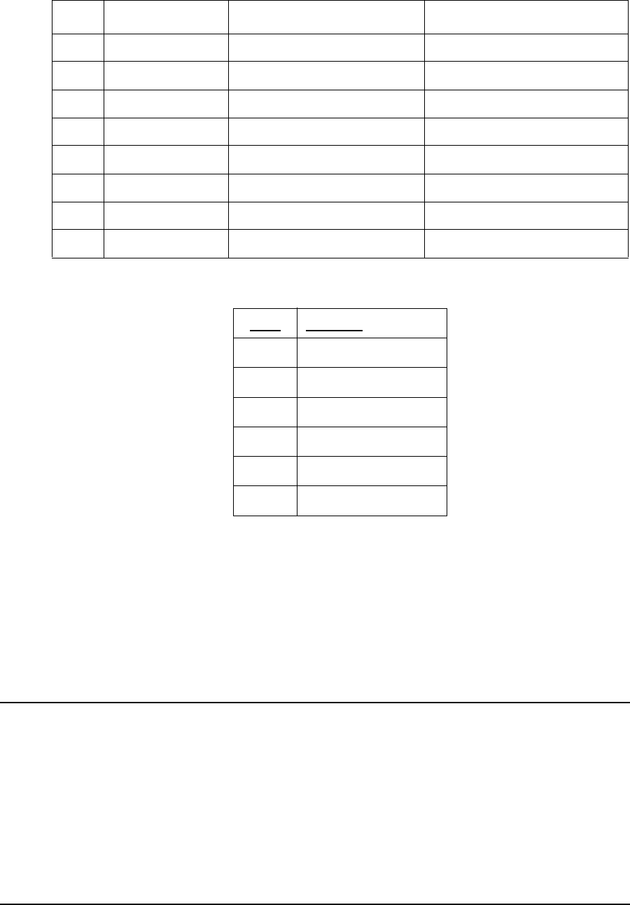
The following table and figures show the definitions of wiring for T568A and T568B
connectors, used to make cross-over and straight-through Ethernet cables as found in ANSI/
TIA/EIA-568-B.2 “Balanced Twisted Pair Cabling Components”.
Table 11 Wiring T568A and T568B ends for Ethernet Cables
Straight-through Ethernet cables have T568A wiring at both ends (or T568B at both ends)
while Cross-over cables have T568A at one end and T568B at the other end.
MMT9000 Physical Interface RJ45 (Ethernet) socket
Wiring standard TIA - T568A
Pin - Pair/Wire - Color
Pin 1 - 3/a - Green/White
Pin 2 - 3/b - Solid Green
Pin 3 - 2/a - Orange/White
Pin 4 - 1/b - Solid Blue
Pin 5 - 1/a - Blue/White
Pin 6 - 2/b - Solid Orange
Pin 7 - 4/a - Brown/White
Pin 8 - 4/b - Solid Brown
TX Data + (Output from MMT9000)
TX Data - (Output from MMT9000)
RX Data + (Input to MMT9000)
Not Used.
Not Used.
RX Data - (Input to MMT9000)
Not Used.
Not Used.
#Description T568A T568B
1Connectors RJ-45 RJ-45
2Wiring standard T568A T568B
3Pair/Wire - Color
3/a – Green/White
3/b – Solid Green
2/a - Orange/White
1/b – Solid Blue
1/a – Blue/White
2/b – Solid Orange
4/a – Brown/White
4/b – Solid Brown
Pin 1
Pin 2
Pin 3
Pin 4
Pin 5
Pin 6
Pin 7
Pin 8
(Pins in bold are different
from T568A)
Pin 3
Pin 6
Pin 1
Pin 4
Pin 5
Pin 2
Pin 7
Pin 8
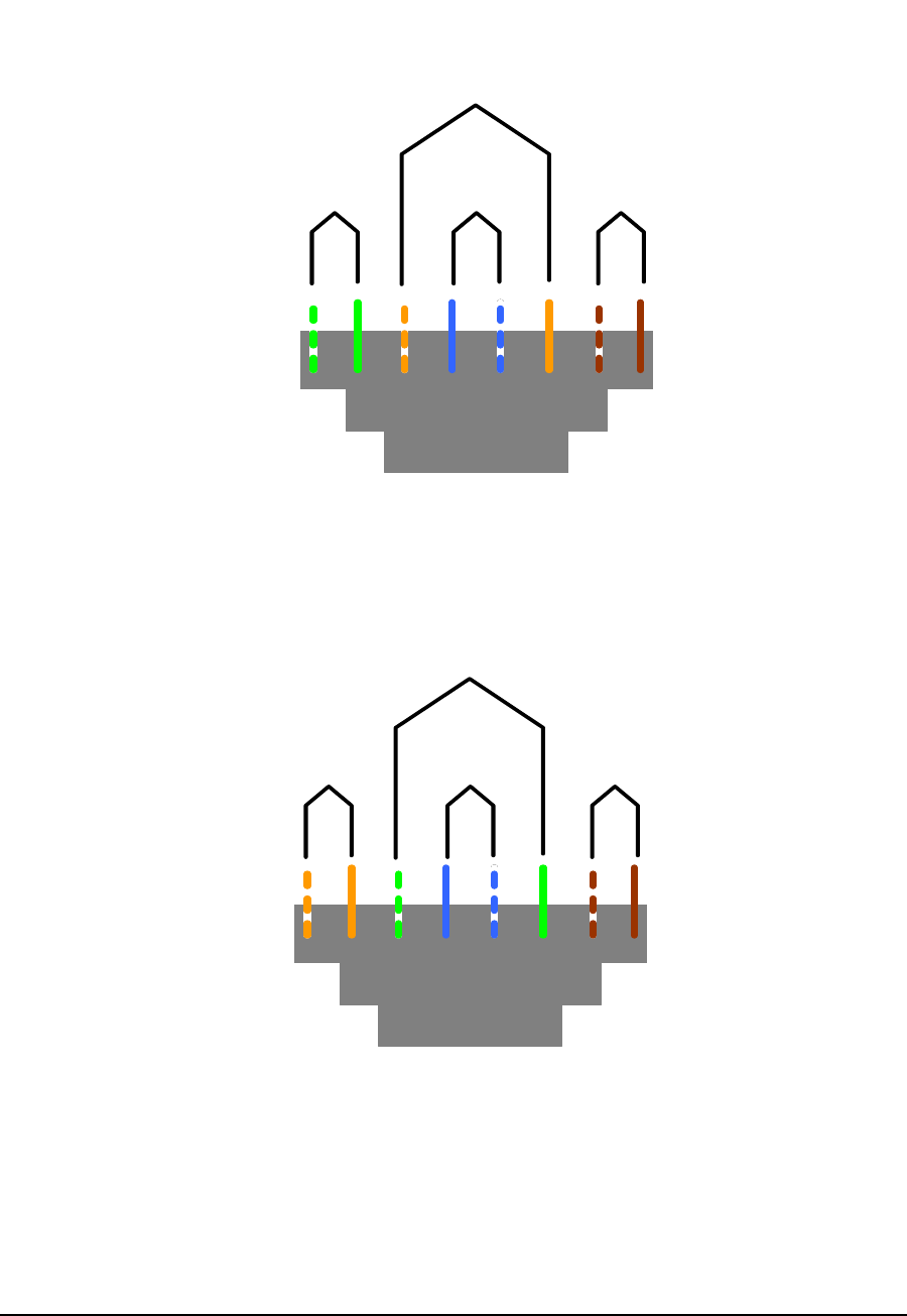
Appendix B: Ethernet Cables and Connectors
APCD-WM001-1.0 31
Figure 7 T568A Wiring
Figure 8 T568B Wiring
Pair 2
T568A W iring Scheme
Pair 3 Pair 1 Pair 4
T568B W iring Scheme
Pair 3
Pair 2 Pair 1 Pair 4