Vecima Networks NCL1100 User Manual Installation and Operation Manual
Vecima Networks Inc. Installation and Operation Manual
Contents
- 1. Installation and Operation Manual
- 2. Change to Users Manual
- 3. Revised RF Safety Satement
Installation and Operation Manual

1990/07/21
NETWORK COMMUNICATIONS LINK 1100
NCL1100
INSTALLATION AND
OPERATION MANUAL
WaveRider Communications Inc.
www.waverider.com

NCL1100 Installation & Operation Manual
1990/07/21 – 2 –
NCL1100 INSTALLATION AND OPERATION MANUAL
© 1999 by WaveRider Communications Inc. All rights reserved. This manual may not be
reproduced in whole or in part without the express written permission of WaveRider
Communications Inc.
The information contained in this manual is subject to change without notice.
FEDERAL COMMUNICATIONS COMMISSION (USA)
This device complies with Part 15 of the FCC rules. Operation of this device is subject to the
following conditions:
• This device may not cause harmful interference.
• This device must accept any interference even if it may cause undesired operation.
• The FCC ID of this device is LXX11.
WARNING
You must install and use this device in strict accordance with
the manufacturer’s instructions, and use it only with the
manufacturer’s supplied antennae, cables, and other
accessories.
There is, however, no guarantee that interference from other radio communications will not
occur in a particular commercial installation. In the event that these devices do cause harmful
interference to an authorized radio service, the user operator must stop operating the devices
until the harmful interference is eliminated.
WaveRider Communications is not responsible for any radio or television interference caused
by improper use of this device, or by the substitution or attachment of connecting cables and
equipment other than specified by WaveRider Communications. The correction of
interference caused by such improper use is the sole responsibility of the user.

NCL1100 Installation & Operation Manual
1990/07/21 – 3 –
Contents
1 INTRODUCTION ....................................................................................................................................4
1-1 Parts List...........................................................................................................................................4
1-2 About the NCL1100 Network Communications Link ........................................................................4
2 INSTALLATION.......................................................................................................................................5
2-1 Preparation .......................................................................................................................................5
2-2 NCL1100 Installation ........................................................................................................................5
2-3 LAN Connection................................................................................................................................7
2-4 Normal Operating Messages............................................................................................................7
2-5 Error Messages ................................................................................................................................7
3 DIAGNOSTICS .......................................................................................................................................7
4 SNMP INSTALLATION .........................................................................................................................11
List of Tables
Table 1: pcagent.cfg Fields and Default Values.........................................................................................12
List of Figures
Figure 1: Potential Obstacles to Line-of-Sight ..............................................................................................6
Figure 2: Back Panel, Indoor Unit.................................................................................................................6
Figure 3: Screen, Normal Mode ...................................................................................................................8
Figure 4: Screen, RF Packets Outgoing.......................................................................................................9
Figure 5: Display for Local RF Site during Testing .....................................................................................10
Figure 6: Display for Remote RF Site during Testing.................................................................................10
Figure 7: Display for Local and Remote Sites During Testing....................................................................11
Figure 8: Spectrum Analyzer Display of Interference .................................................................................11
Table of Revisions
Revision Date Comments
July 21, 1999 Preliminary user manual release

NCL1100 Installation & Operation Manual
1990/07/21 – 4 –
1 Introduction
This manual explains how to install an NCL1100 Network Communications Link system and
operate it in an Ethernet or Token Ring environment, either under IEEE 802.3 or Ethernet II
specifications. Ethernet II is not supported at this time for the Token Ring to Ethernet bridge,
only Token Ring to IEEE 802.2/802.3 is supported. WaveRider Communications can only
provide support for hardware and software that are sold with the NCL1100. WaveRider
Communications does not provide support for any third-party equipment.
If you purchased an outdoor antenna kit, use its manual for detailed instructions about how to
install a directional antenna.
1-1 Parts List
The parts included in the NCL1100 package are:
• one bridge
• one power cord
• this manual
If any parts are missing, please contact your vendor.
1-2 About the NCL1100 Network Communications Link
The NCL1100 Network Communications Link is a platform upon which a LAN transmission
system is built. Its basic capabilities include MAC-layer address filtering for traffic
management and security. In addition to this, it can use RF techniques to transmit to another
site. The NCL1100 configuration you purchased includes the spread-spectrum interface for
transmission at speeds up to 11 million bits per second (11 Mb/s).
The system consists of an indoor unit that functions as a MAC layer bridge. It contains the
cards needed to interface to the LAN and to provide RF communications to the other site.
The system utilizes an outdoor antenna, lightning protector, and connecting cable.
The NCL1100 is a MAC layer, self-learning bridge that supports all Ethernet 802.2/802.3 and
Ethernet II Protocols, and Token Ring (Token Ring use has restraints that you must follow).
These protocols include:
• Novell IPX, SPX
• Decnet
• LAT
• TN3270
• TCP/IP
• UDP/IP
• SNMP
• XNS/MS
• Appletalk
• ISO
• Banyan Vines

NCL1100 Installation & Operation Manual
1990/07/21 – 5 –
The NCL1100 unit determines its environment at power-up, and builds its own address tables
based on the observed activity on the LAN segment to which it is attached. The system is
designed this way to minimize the required set-up and user administration.
2 Installation
Although the NCL1100 Network Communications Link is as user-friendly as possible, keep in
mind the design considerations. The NLC1100 is a complete point-to-point microwave
system that uses spread-spectrum techniques. Take the same precautions as you do when
you install any microwave system.
2-1 Preparation
Evaluate the path length and characteristics. Unless the path fits the default characteristics,
have a qualified engineer perform path calculations. The default characteristics include using
50 feet (16.7 m) of coaxial cable between the antenna and the indoor system. The maximum
distance between the antennae is 5 miles (8 km). You can make trade-offs with these
factors, such as extending the cable length by having a higher-gain antenna or having a path
shorter than 5 miles (8 km). As distance increases, you must maintain proper obstacle
clearance.
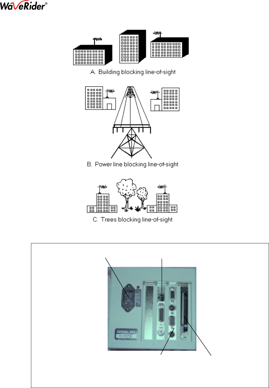
Ensure that the line-of-sight exists; refer to Figure 1. You have a clear line-of-sight when you
can clearly see the remote site, as well as the required Fresnel zone clearance, when you
stand on the first site and look towards the second site. As well, ensure that there are no
large reflective surfaces on the path, such as large buildings with metallic glass surfaces or
crowded parking lots. Avoid installation on tall downtown buildings where higher-powered
systems are installed, because of potential interference.
2-2 NCL1100 Installation
You must install the indoor unit in a temperature-controlled environment, and provide a
110/230 VAC outlet. The unit draws less than 5 amps. The indoor unit is stand-alone and
can sit on a shelf or desk, or you can mount it on the wall with the optional wall-mount
brackets. Do not power up the units until they are connected to the LAN and RF interfaces at
both sites; refer to Figure 2. This is necessary to ensure that the start-up diagnostic tests
pass, and proper terminations prevent the equipment from damage. As well as the
110/230 VAC, 50/60 Hz connection and a coaxial cable from the antenna, make a third
connection to the indoor unit from the LAN itself. This connection is available in three types
on the back of the unit: 10BASE-T, AUI, and BNC.
WARNING!
You may cause permanent damage to the unit if any NCL1100 RF
port is not terminated correctly and you power up the unit.
Connect the indoor unit to a 110/230 VAC, 50/60 Hz power outlet.
NCL1100 Installation & Operation Manual
1990/07/21 – 6 –
Figure 1: Potential Obstacles to Line-of-Sight
Figure 2: Back Panel, Indoor Unit
110/220 VAC 10BASE-T, AUI, or BNC Ports
CPU card RF card

NCL1100 Installation & Operation Manual
1990/07/21 – 7 –
2-3 LAN Connection
The port for the network interface card includes three interfaces: an AUI connector, a
10BASE-T connector, and a BNC or 10BASE-2 connector. You can only use one port at a
time and this is determined automatically during the boot or start-up process; therefore, you
must connect the LAN before you power up the bridge.
Do not power up the NCL1100 system until you make all the connections. If you power it up
before you make the connections, you may need to power it down, then up again after you
make the connections.
Once you make the proper connections, the system immediately begins building address
tables of nodes located on the local and remote LANs. It uses these tables to filter packets
not destined for the remote LAN, thereby maximizing throughput capability.
NOTE: If you move a node from one side of the NCL1100 connection to the other, you
can power both systems off, then on, so that they can re-establish the table
necessary for the new node location. Alternatively, press the b key on the
keyboard at each unit, while the NCL1100 system is running, to re-establish the
table necessary for the new node location.
2-4 Normal Operating Messages
During normal operation, the NCL1100 system displays these messages:
• Testing RF Interface Card…
• Testing LAN interface Card…
• Cards Initialized…
2-5 Error Messages
When there are problems, the system displays these error messages:
• Unable to open file The InterBuilding Link.CFG
Cause: The configuration file for IBL.EXE was not present in the current directory
when you started the NCL1100, or the file does not exist.
Cure: Type dir and the file name at the C> prompt to ensure that the IBL.EXE
and Link.CFG files are present. If the files are not present, use the
WaveRider Communications website at www.waverider.com for
technical support.
• Network Card Error : Loopback test failed
Cause: The NCL1100 could not perform a successful loopback test on the
network card. The failure may be due to an incorrect cable connection,
incorrect cable termination, or a severe network load during the loopback
test.
Cure: Ensure that the LAN cable is connected and terminated properly, then try
again. If the problem persists, disconnect the network card and
terminate it, then try again. If this fails, replace the card.
3 Diagnostics
The NCL1100 has a VGA-compatible output connector on the back of the unit. If you
experience problems with the system, plug a standard VGA-compatible monitor into this
connector to display the diagnostic screens. Once you connect a VGA-compatible monitor to

NCL1100 Installation & Operation Manual
1990/07/21 – 8 –
the unit, you can monitor several things while the link is operating, without affecting the link.
Also, you can add a standard PC keyboard to execute other diagnostic commands.
As the NCL1100 loads, the initial test routines display messages. A failed test points to the
possible problem, such as a poor LAN or RF connection on the back of the unit.
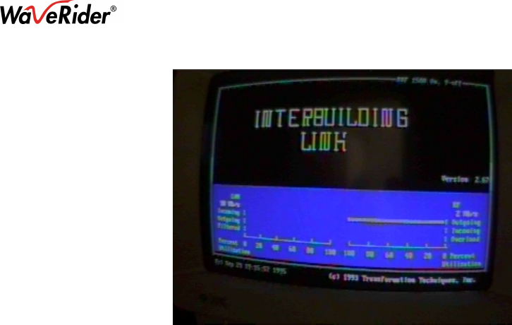
After the Network Communications Link is loaded, it displays an inactive status screen. To
activate the status screen, press the R key once. The system begins to display activity in real
time, and updates the display screen approximately once every second. The information
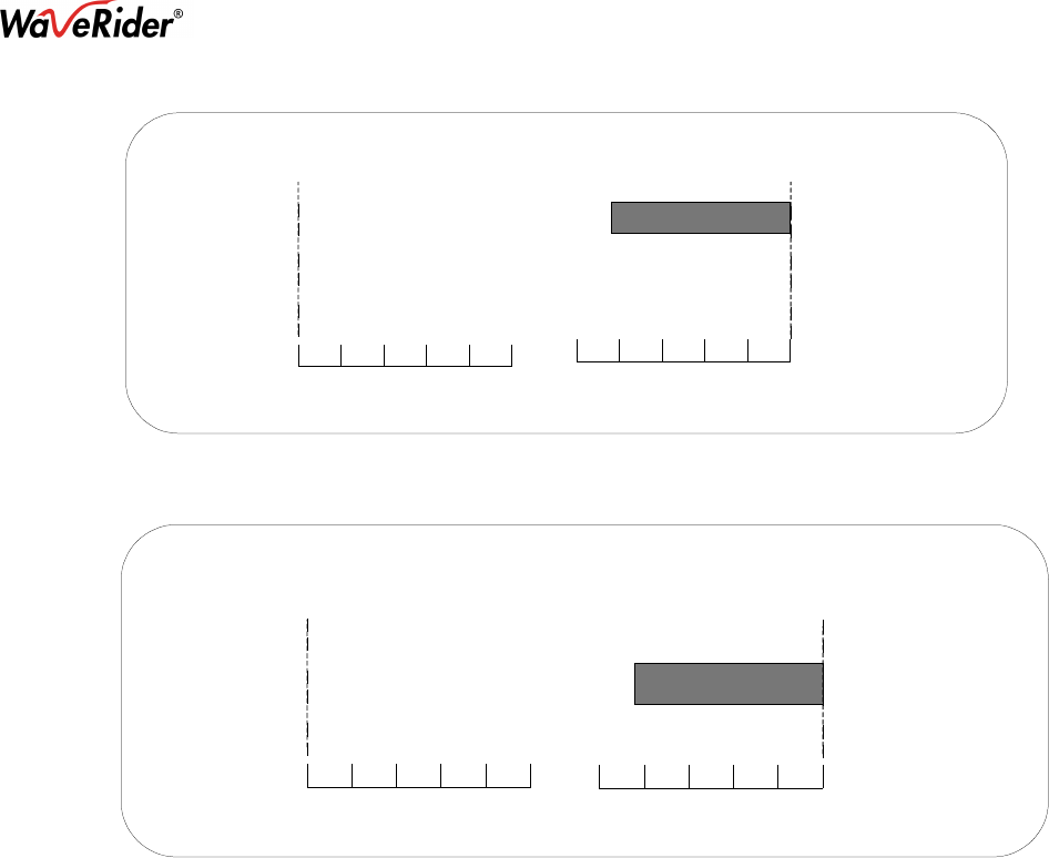
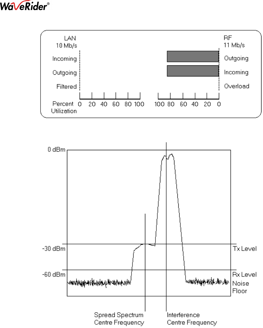
includes the bar graphs illustrated in Figure 5, Figure 6, and Figure 7.
RF Outgoing, Incoming:
The graph on the right-hand side of the screen shows the transmitting
and receiving utilization per second of the RF section of the system.
LAN Outgoing, Incoming:
The graph on the left-hand side of the screen shows the transmitting and
receiving utilization per second of the LAN section of the system.
Filtered: The graph on the left-hand side of the screen shows the percentage of
incoming LAN packets that were filtered.
Overload: This is the percentage of incoming LAN packets that are discarded due
to full internal buffers. The packets are discarded by the FIFO method,
i.e., the oldest packet is discarded first.
All throughput displays are a percent of utilization, that is, the graph is from zero to one
hundred percent, which is the percentage of total throughput available. On an 11 Mb/s link,
one hundred percent throughput equals 11 Mb/s.
Figure 3 is the display screen in the normal mode, with no packet activity to generate bar
graphs on the screen.
Figure 4 is a diagnostic screen that shows RF packets outgoing. Note that since only one
bridge is transmitting, the outgoing utilization is 100%. On the 11 Mb/s, however, the
maximum utilization is 84%, with the packet size set at 1514 (T 1514 then <Enter>).
Figure 3: Screen, Normal Mode
NCL1100 Installation & Operation Manual
1990/07/21 – 9 –
Figure 4: Screen, RF Packets Outgoing
As well as the normal display screen, the NCL1100 has a diagnostic utility included. This
utility diagnoses the RF link; use it only if the NCL1100 display shows that the RF link failed
(no incoming and/or outgoing packets).
After you run the tt and yy RF tests, connect the LAN and attempt communication across the
link. By leaving the LAN disconnected until you run all RF tests, you can determine which
side of the link has the problem, LAN or RF.
Press these keys: to have this happen:
T T <Enter> 1496-byte packets are sent in one direction
Y Y <Enter> 1496 byte packets go in both directions and activate the remote unit
The screen displays the packets sent and received by the system. These packets are test
packets of approximately 1496 bytes in length. The bar graphs on the lower half of the screen
show the packets received and sent since the last screen update. The system updates the
screen approximately once/second. Outgoing packets are shown even if the RF link, between
the local and remote RF sites, is not working. If the RF link is not working, however, no
incoming RF packets are shown at the remote RF site even if the local RF site is placed in a
test mode so that the local site generates outgoing RF packets. If only one end is transmitting
and the other end is receiving, then the RF utilization shows 84% incoming at the remote site
and 84% outgoing at the local site, unless interference or another system decreases
performance. Refer to Figure 5 and Figure 6. To terminate this test, power off and then on
both indoor units, or press T or Y once.
NCL1100 Installation & Operation Manual
1990/07/21 – 10 –
Figure 5: Display for Local RF Site during Testing
Incoming
Outgoing
Filtered
Incoming
Outgoing
Percent
Utilization
Overload
LAN RF
11 Mb/s
10 Mb/s
020406080100
0 20 40 60 80 100
Figure 6: Display for Remote RF Site during Testing
Incoming
Outgoing
Filtered
Incoming
Outgoing
Percent
Utilization
Overload
LAN RF
11 Mb/s
10 Mb/s
020406080100
020406080100
You can use a second diagnostic method to test the RF link, but it does not test the hardware.
To perform this test, follow these instructions:
1. Power both indoor units off, then on, to ensure that you use the proper command line
during the test procedure.
2. After the NCL1100 system is running and the display screen appears at both sites, at the
local site press the R key to activate the display, then press yy. This action places both
RF sites in the test mode, sending and receiving the opposite site’s packets.
3. When both sites are transmitting and receiving test packets, check that the RF utilization
shows approximately 44% incoming and outgoing at both the local and remote sites.
Figure 7 illustrates the monitors for both the remote and local RF sites, when both sites
are transmitting and receiving. This is the yy test.
4. If the incoming RF utilization is less than 44%, then the RF link portion of the system is
suspect. Focus your trouble-shooting on the coaxial cable, antenna, or interference.
5. If the RF link is not working, the coaxial cable is connected properly, and the antennae
are in unobstructed alignment with each other, then you many need a spectrum analyzer
(refer to Figure 8) to pinpoint interfering frequencies and take corrective action. You can,
however, move the antenna slightly in an alignment-type pattern, while it is on its mast, to
correct the problem; or use nearby objects to shield the antenna from the offending
frequency.
NCL1100 Installation & Operation Manual
1990/07/21 – 11 –
Figure 7: Display for Local and Remote Sites During Testing
Figure 8: Spectrum Analyzer Display of Interference
4 SNMP Installation
This section describes how to configure and use SNMP (simple network management
protocol) on the wireless link. The wireless bridge includes an SNMP agent that collects
valuable statistical and configuration information about the network interface card inside your
wireless link. Network administrators analyze this information to keep their networks
operating at peak efficiency.
The SNMP agent maintains a database of statistical and configuration information in RAM. It
obtains this information directly from the wireless bridge during operation. With this true

NCL1100 Installation & Operation Manual
1990/07/21 – 12 –
SNMP agent, any SNMP manager (e.g., Hewlett Packard’s Openview, Sun Microsystem’s
SunNet Manager) can directly monitor the LAN side of the wireless bridge.
If you purchased the SNMP upgrade package, you can use the SNMP agent with IPX and
TCP/IP networks. Although the SNMP agent does not require you to load a particular
operating system or protocol stack, an IP address must be available if it is to communicate
with SNMP stations using TCP/IP protocol. You can configure the SNMP at any time.
You need a monitor and keyboard to configure the SNMP agent in the wireless bridge. An
editor is included with the bridge to allow you to edit a file called pcagent.cfg. The agent is
configured when you use the editor to edit this file. The procedure for using this editor is:
1. From the main service monitoring screen that shows the bar graphs, press the X key.
The system exits the bridge’s normal operating mode and displays a DOS-like prompt.
2. At this prompt, type CLS and then press <Enter> to clear the screen.
3. Type
E pcagent.cfg and press <Enter>.
4. Edit the displayed fields or accept the defaults. Refer to Table 1 for the fields and their
default values.
5. Hold down the <ALT> key and press the X key to exit and save the file.
6. Hold down the <CTRL> and <ALT> keys, and press the <DELETE> key to reboot the system
and return it to the normal operating mode, or power off and on the system again.
Table 1: pcagent.cfg Fields and Default Values
Field Default Value
ComStr TTI
sysContact TTI
sysName TTI
sysLocation TTI
smcDosWsIpAdr * 123.123.001.001
smcDosWsTrapDstAdr.1 † 123.123.002.002
smcDosWsTrapDstPro.1 ‡ 2
smcDosWsTrapDstAdr.2 † 123.123.003.003
smcDosWsTrapDstPro.2 ‡ 2
smcDosWsTrapDstAdr.3 † 123.123.004.004
smcDosWsTrapDstPro.3 ‡ 2
• * smcDosWsIpAdr is the IP address string in the configuration file. It is assigned a value
in the form X.X.X.X, where each X is a value from 0 to 255. The alphabetic object name
is upper- and lower-case sensitive. You need an IP address if agent/SNMP
communicates with SNMP management stations using the TCP/IP protocol.
• † In a TCP/IP network, these are IP addresses of network management stations to which
to send traps (alerts) if an alarm occurs.
In an IPX network, these are IPX network addresses (e.g., smcDosWsTrapDstAdr.1) of
the network management stations where traps are sent. Traps can be sent to a
maximum of three management stations (Adr.1, Adr.2, and Adr.3).
• ‡ In an IPX network, if the network management station is on another network, the
protocol specified here must be acceptable to the router on the local network.
An example is smcDosWsTrapDstPro.1 = 2. The protocols include:
1 = not used

NCL1100 Installation & Operation Manual
1990/07/21 – 13 –
2 = TCP/IP (Ethernet and Token Ring)
3 = IPX with Ethernet II frame type (Ethernet only)
4 = IPX with 802.2 (LLC) frame type (Ethernet and Token Ring)
5 = IPX with SNAP frame type (Ethernet and Token Ring)
6 = IPX with 802.3 frame type (Ethernet only)