Vecima Networks TR2126SE TR2126SE MMDS/MDS Transceiver User Manual
Vecima Networks Inc. TR2126SE MMDS/MDS Transceiver
UserManual.wiki
>
Vecima Networks
>
TR2126SE User Manual
User manual
Navigation menu
Upload a User Manual
Namespaces
Wiki Guide
HTML
PDF
Info
Views
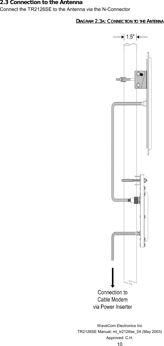
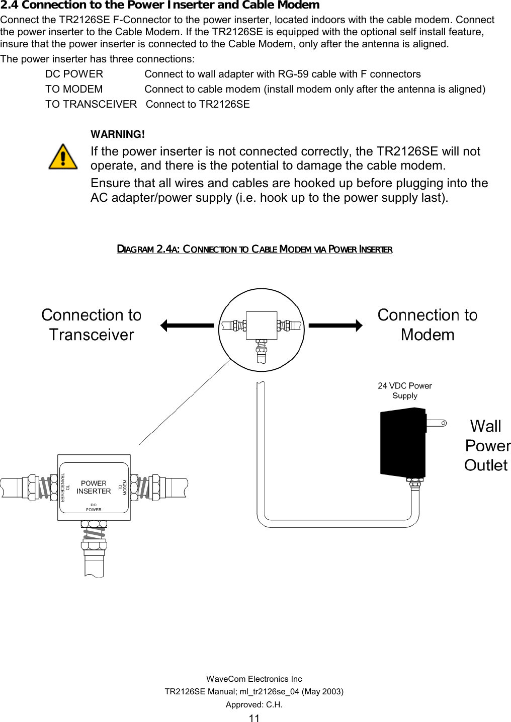
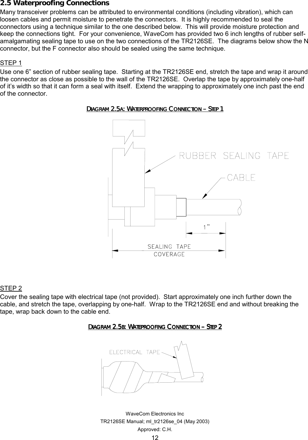
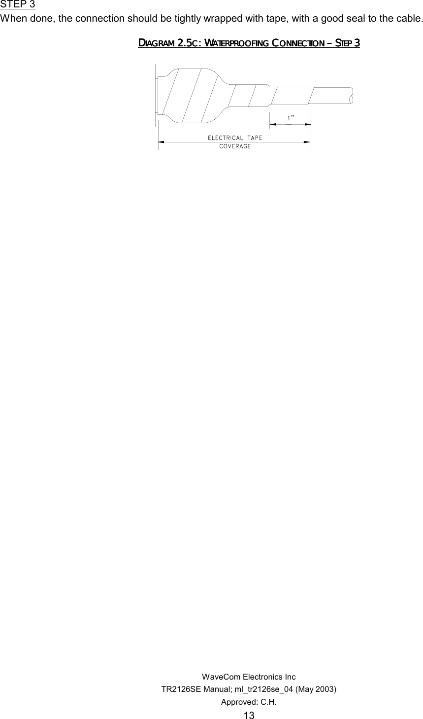
User Manual
Discussion / Help
Navigation