Vecima Networks TR2126SE TR2126SE MMDS/MDS Transceiver User Manual
Vecima Networks Inc. TR2126SE MMDS/MDS Transceiver
User manual
MDS/MMDS Transceiver
TR2126SE
INSTALLATION AND OPERATION
GUIDE FOR SYSTEM OPERATORS

WaveCom Electronics Inc
TR2126SE Manual; ml_tr2126se_04 (May 2003)
Approved: C.H.
ii
Proprietary to WaveCom Electronics Inc.
All rights reserved.
No part of this publication may by reproduced in any form or by any means or used to make any derivative work (such as translation,
transformation or adaptation) without written permission from WaveCom Electronics Inc.
WaveCom Electronics Inc. reserves the right to revise this publication and to make changes in content from time to time without obligation
on the part of WaveCom Electronics Inc. to provide notification of such revision or change.
WaveCom Electronics Inc. provides this guide without warranty of any kind, either implied or expressed, including, but not limited to, the
implied warranties of merchantability and fitness for a particular purpose. WaveCom Electronics Inc. may make improvements or
changes in the product(s) described in this manual at any time.
TR2126SE Manual; ml_tr2126se_04 (May 2003); Approved: C.H.
Specifications subject to change without notice — Printed in Canada
WaveCom Electronics Inc
TR2126SE Manual; ml_tr2126se_04 (May 2003)
Approved: C.H.
iii
Thank-you for purchasing this product and
welcome to WaveCom!
You have chosen an innovative solution from a leading
technology design center in the ongoing TV & data delivery
revolution.
No doubt you’ve been thinking that the future of your television delivery system includes new technologies
such as Digital TV, Internet Over Cable, Wireless Cable. By selecting WaveCom, you are benefiting from
the same design powerhouse that since 1988 has created custom RF and digital products for technology
leaders such as AT&T, Cisco Systems, Cogeco, Comcast, and Cox Communications.
WaveCom designs and manufactures:
✔
✔✔
✔Agile CATV Modulators ✔
✔✔
✔256 QAM Upconverters ✔
✔✔
✔Digital Video Modulators
✔
✔✔
✔Frequency Translators ✔
✔✔
✔Spread Spectrum Devices ✔
✔✔
✔Off-Air Demodulators
✔
✔✔
✔Video-On-Demand Products ✔
✔✔
✔Wireless Cable MMDS ✔
✔✔
✔Wireless Cable LMDS
✔
✔✔
✔Frequency Stackers ✔
✔✔
✔MMDS Transceivers ✔
✔✔
✔Satellite Receivers
and more! Designs to fill the market needs of the CATV industry – both foreign and domestic.
For additional product or corporate information, contact us:
On the web at: www.WaveCom.ca
By sending email to: sales@WaveCom.ca
By telephone: (306) 955-7075
By fax: (306) 955-9919
By snail mail: WaveCom Electronics Inc.
150 Cardinal Place
Saskatoon, SK Canada S7L 6H7
WaveCom's Corporate Mandate
is to be a leading worldwide designer and manufacturer of state-
of-the-art communications equipment and components. Through
the remarkable success of our customers and business partners,
WaveCom innovations are achieving this goal.

WaveCom Electronics Inc
TR2126SE Manual; ml_tr2126se_04 (May 2003)
Approved: C.H.
iv
SAFETY PRECAUTIONS
1. Before installing and operating this equipment, read all Safety, Installation and Operating sections. Retain
this manual for future reference.
2. Follow all instructions — Failure to do so may result in damage to the unit or severe personal injury.
3. Servicing should not be attempted by the user. There are no user serviceable parts inside. Refer all
servicing to factory qualified personnel.
4. Shock Hazard — An electrical shock hazard exists when the chassis cover is removed as is required to set
internal controls. Always disconnect power from the unit before removing the cover.
5. Cleaning — Do not use liquid or aerosol cleaners. Use a damp cloth for cleaning.
Warning Do not work on the system or connect or disconnect cables during periods of lightning activity.
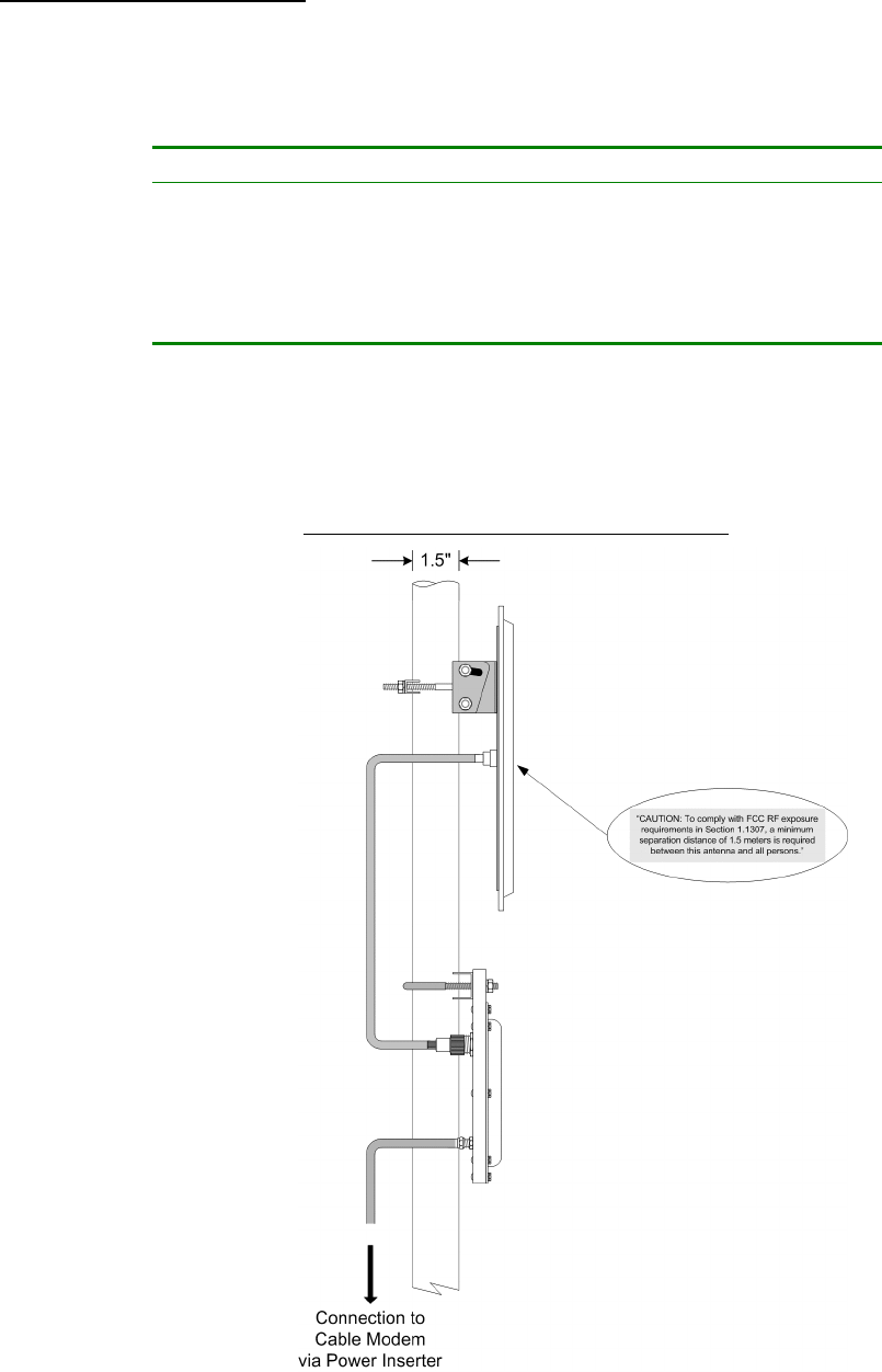
CAUTION: To comply with FCC RF exposure requirements in section 1.1307, a minimum separation
distance of 1.5 meters is required between this antenna and all persons.
LES PRÉCAUTIONS DE SÉCURITÉ
1. Avant d'installer ou d'opérer cet équipement, lisez, toutes les sections de sécurités, d'installations et
d'opérations. Gardez ce manuel comme source de référence.
2. Suivez toutes instructions - si non, vous risquez d'endommager la machine ou de vous blesser
sérieusement.
3. N'essayez, pas de réparer cet équipement vous même. Référez toutes revisions nécessaire au personnel
qualifié de la manufacture.
4. Risque de choc - Il y a un risque de décharge électrique qui existe quand la couverture du châssis est
enlevée, comme est nécessaire pour ajuster les contrôlcs internes. Il faut toujours couper l'électricité avant
d'enlever le couvercle pour faire aucun ajustage.
5. Le nettoyage - n'utilisez pas de nettoyeurs aérosols ou liquides. Utilisez un tissu humide pour nettoyer.
Attention Ne pas travailler sur le système ni brancher ou débrancher les câbles pendant un orage du
foudre.
CAUTION: To comply with FCC RF exposure requirements in section
1.1307, a minimum separation distance of 1.5 meters is required between
this antenna and all persons.
☛ Important Installation Instructions

WaveCom Electronics Inc
TR2126SE Manual; ml_tr2126se_04 (May 2003)
Approved: C.H.
v
INDEX
1.0 GENERAL INFORMATION ....................................................................................................... 6
1.1 Functional Overview..............................................................................................................................6
1.2 Module Features.....................................................................................................................................6
1.3 Specifications..........................................................................................................................................7
2.0 INSTALLATION.......................................................................................................................... 8
2.1 Unpacking the Unit................................................................................................................................8
2.2 Mounting the Unit..................................................................................................................................8
2.2.1 Mounting the TR2126SE...................................................................................................................................8
2.2.2 Mounting the Antenna .......................................................................................................................................9
2.3 Connection to the Antenna..................................................................................................................10
2.4 Connection to the Power Inserter and Cable Modem.......................................................................11
2.5 Waterproofing Connections................................................................................................................12
3.0 TUNING THE ANTENNA ........................................................................................................ 14
3.1 Preparation for Tuning .......................................................................................................................14
3.2 Signal Strength and Alignment...........................................................................................................14
3.3 Resetting the Beeper ............................................................................................................................14
4.0 WARRANTY STATEMENT AND SERVICE POLICY .......................................................... 15
4.1 Warranty Statement ............................................................................................................................15
4.2 Service Policies: How to Return an Item for Service:.......................................................................15
4.3 Repair Charges and Warranty Exemptions......................................................................................16

WaveCom Electronics Inc
TR2126SE Manual; ml_tr2126se_04 (May 2003)
Approved: C.H.
6
1.0 GENERAL INFORMATION
1.1 Functional Overview
The WaveCom TR2126SE is an MDS/MMDS Transceiver for use in wireless systems. The TR2126SE
integrates an LNA, downconverter, upconverter, power amplifier, RF and IF diplexers to provide a one-box
solution for two-way wireless RF communications. The TR2126SE and antenna are situated outdoors and
connected to a cable modem indoors by standard RG-59 cable. A single RF connector on the weatherproofed
enclosure provides the interface to the transmit/receive antenna for rapid setup. The Transceiver is
configured to work with standard cable modem frequency plans and levels, permitting direct connection. The
Transceiver also includes an RF mute function to reduce power consumption and broadband noise emissions.
1.2 Module Features
• +27 dBm output for high reverse channel system gain
• Microprocessor controlled gain compensation over temperature
• Low Phase Noise
• Automatic transmit RF mute (transmits only when an IF signal is present)
• Fully weatherized unit, suitable for outdoor mounting
• Audible self install indicator (optional feature)

WaveCom Electronics Inc
TR2126SE Manual; ml_tr2126se_04 (May 2003)
Approved: C.H.
7
1.3 Specifications
UPCONVERTER SPECIFICATIONS
IF Input Frequency 14.375 to 26.375 MHz
RF Output Frequency 2150 to 2162 MHz
Output (1dB Compression Point) +27 dBm
Gain 20 ± 2 dB across full temperature range
Gain Flatness +/- 1 dB
In-band Spurious -60 dBc
Out-of-band Spurious -60 dBc
Phase Noise -93 dBc/Hz @ 10 kHz
-115 dBc/Hz @ 100 KHz
IF Level for RF Activation +3 dBmV
DOWNCONVERTER SPECIFICATIONS
RF Input Frequency 2500 to 2686 MHz
IF Output Frequency 222 to 408 MHz
Nominal Gain 32 ± 2 dB
Gain Flatness +/- 1.5 dB; ± 0.3 dB/ 6 MHz
Noise Figure ≤5.0 dB @ 20C, typically 4.0 dB
Output 3rd Order Intercept +22 dBm at nominal gain
WCS Rejection 70 dB
Combined Image and PCS Rejection 85 dB
Spurious -65 dBm max.
Phase Noise -93 dBc/Hz @ 10 kHz
-115 dBc/Hz @ 100 kHz
GENERAL
Frequency Setting & Stability ± 7.5 kHz (-40 to +60°C)
Frequency Stability Over Time <±10 kHz over 10 years
RF Connector N female, 50 ohms
IF Connector F female, 75 ohms
Input/Output VSWR 2:1
DC Supply 12 to 24 V, 12 Watts max.
Operating Temperature -40 to +60°C (-40 to +140°F)
Size 6" x 8" x 0.9" (15.24 x 20.32 x 2.29 cm)
Mounting Pole mount (1” to 1.75” (25mm to 44mm) diameter)
Specifications subject to change without notice.
WaveCom Electronics Inc
TR2126SE Manual; ml_tr2126se_04 (May 2003)
Approved: C.H.
8
2.0 INSTALLATION
2.1 Unpacking the Unit
Carefully remove the equipment from its packing material and set it on a solid surface, such as a table or
desk. If it appears damaged in any way, notify the carrier, and keep all packing materials for inspection by the
carrier’s agent.
2.2 Mounting the Unit
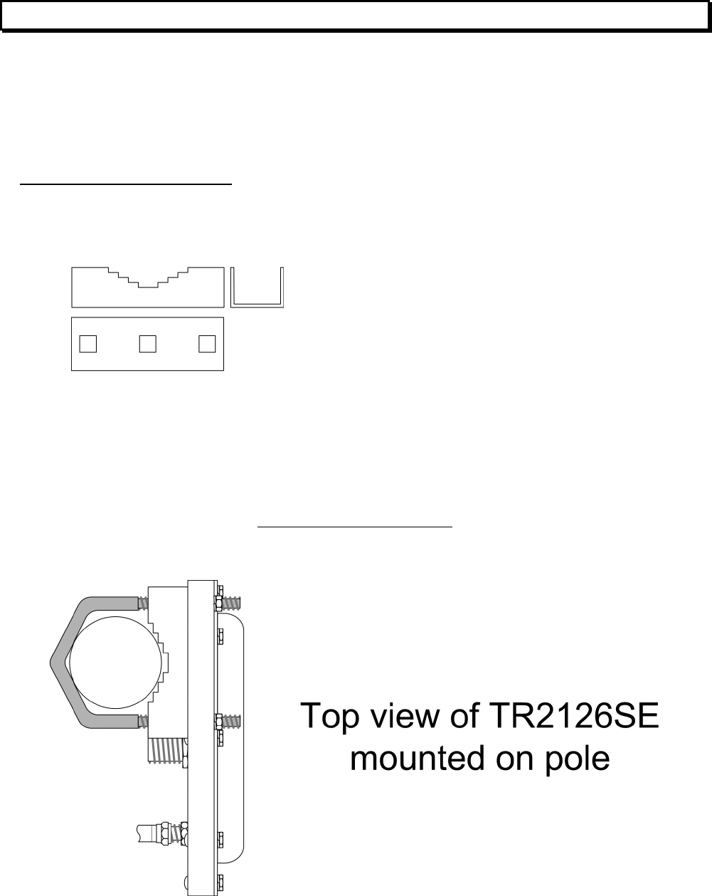
2.2.1 Mounting the TR2126SE
The following hardware is included in the box for mounting the TR2126SE to the pole:
• 1 pole catch
• 1 V-bolt
• 2 ¼”x20 flange locknuts for connecting V-bolt and pole catch to the pole
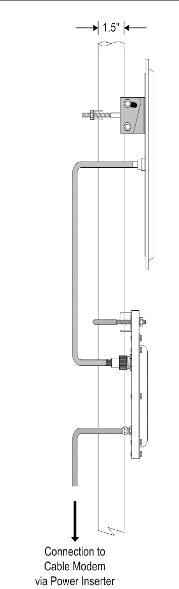
The TR2126SE was designed for mounting to a pole with a diameter of 1.0" to 1.75". Please ensure that the
pole used is attached securely to the building or other mounting location. Simply secure the TR2126SE unit to
a pole as shown in Figure 2.2A with F-Connector on the bottom.
D
DD
DIAGRAM
IAGRAM IAGRAM
IAGRAM 2.2
2.22.2
2.2A
AA
A: M
: M: M
: MOUNTING THE
OUNTING THE OUNTING THE
OUNTING THE U
UU
UNIT
NITNIT
NIT
WaveCom Electronics Inc
TR2126SE Manual; ml_tr2126se_04 (May 2003)
Approved: C.H.
9
2.2.2 Mounting the Antenna
Mount the antenna according to the manufacturer’s instructions.
☛ The TR2126SE is intended for use with flat planar arrays and dipole/parabolic reflectors. Please
consult table 2.2B for further information.
☛ Table 2.2B: Antenna List
Transceiver Power Antenna Type Antenna Gain
(Watts) (dBm) (dBi)
0.316 25 Flat planar array 12
0.316 25 Flat planar array 18
0.316 25 Dipole/parabolic reflector 21
0.316 25 Dipole/parabolic reflector 24
☛ Included with the TR2126SE unit is a self-adhesive label for application to the antenna. To
operate the TR2126SE in compliance with FCC regulations, you must apply the included label to
the antenna. Peel off the protective backing from the label and affix it to the antenna such that
the label is readable from a distance of 5 feet.
D
DD
DIAGRAM
IAGRAM IAGRAM
IAGRAM 2.2
2.22.2
2.2C
CC
C: A
: A: A
: APPLYING THE
PPLYING THE PPLYING THE
PPLYING THE S
SS
SELF
ELFELF
ELF-
--
-A
AA
ADHESIVE
DHESIVE DHESIVE
DHESIVE L
LL
LABEL
ABELABEL
ABEL
WaveCom Electronics Inc
TR2126SE Manual; ml_tr2126se_04 (May 2003)
Approved: C.H.
10
2.3 Connection to the Antenna
Connect the TR2126SE to the Antenna via the N-Connector
D
DD
DIAGRAM
IAGRAM IAGRAM
IAGRAM 2.3
2.32.3
2.3A
AA
A: C
: C: C
: CONNECTION TO THE
ONNECTION TO THE ONNECTION TO THE
ONNECTION TO THE A
AA
ANTENNA
NTENNANTENNA
NTENNA
WaveCom Electronics Inc
TR2126SE Manual; ml_tr2126se_04 (May 2003)
Approved: C.H.
11
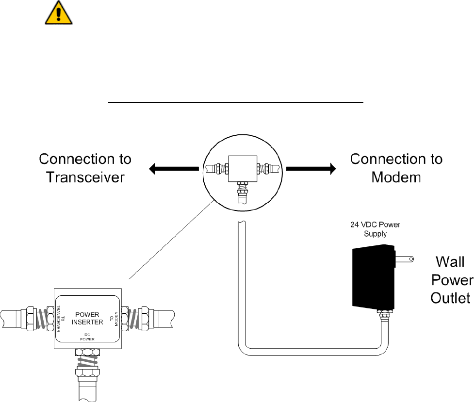
2.4 Connection to the Power Inserter and Cable Modem
Connect the TR2126SE F-Connector to the power inserter, located indoors with the cable modem. Connect
the power inserter to the Cable Modem. If the TR2126SE is equipped with the optional self install feature,
insure that the power inserter is connected to the Cable Modem, only after the antenna is aligned.
The power inserter has three connections:
DC POWER Connect to wall adapter with RG-59 cable with F connectors
TO MODEM Connect to cable modem (install modem only after the antenna is aligned)
TO TRANSCEIVER Connect to TR2126SE
WARNING!
If the power inserter is not connected correctly, the TR2126SE will not
operate, and there is the potential to damage the cable modem.
Ensure that all wires and cables are hooked up before plugging into the
AC adapter/power supply (i.e. hook up to the power supply last).
D
DD
DIAGRAM
IAGRAM IAGRAM
IAGRAM 2.4
2.42.4
2.4A
AA
A: C
: C: C
: CONNECTION TO
ONNECTION TO ONNECTION TO
ONNECTION TO C
CC
CABLE
ABLE ABLE
ABLE M
MM
MODEM VIA
ODEM VIA ODEM VIA
ODEM VIA P
PP
POWER
OWER OWER
OWER I
IIINSERTER
NSERTERNSERTER
NSERTER
WaveCom Electronics Inc
TR2126SE Manual; ml_tr2126se_04 (May 2003)
Approved: C.H.
12
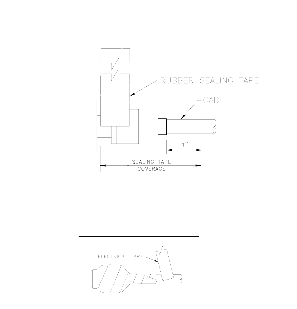
2.5 Waterproofing Connections
Many transceiver problems can be attributed to environmental conditions (including vibration), which can
loosen cables and permit moisture to penetrate the connectors. It is highly recommended to seal the
connectors using a technique similar to the one described below. This will provide moisture protection and
keep the connections tight. For your convenience, WaveCom has provided two 6 inch lengths of rubber self-
amalgamating sealing tape to use on the two connections of the TR2126SE. The diagrams below show the N
connector, but the F connector also should be sealed using the same technique.
STEP 1
Use one 6” section of rubber sealing tape. Starting at the TR2126SE end, stretch the tape and wrap it around
the connector as close as possible to the wall of the TR2126SE. Overlap the tape by approximately one-half
of it’s width so that it can form a seal with itself. Extend the wrapping to approximately one inch past the end
of the connector.
D
DD
DIAGRAM
IAGRAM IAGRAM
IAGRAM 2.5
2.52.5
2.5A
AA
A: W
: W: W
: WATERPROO
ATERPROOATERPROO
ATERPROOFING
FING FING
FING C
CC
CONNECTION
ONNECTION ONNECTION
ONNECTION –
––
– S
S S
STEP
TEP TEP
TEP 1
11
1
STEP 2
Cover the sealing tape with electrical tape (not provided). Start approximately one inch further down the
cable, and stretch the tape, overlapping by one-half. Wrap to the TR2126SE end and without breaking the
tape, wrap back down to the cable end.
D
DD
DIAGRAM
IAGRAM IAGRAM
IAGRAM 2.5
2.52.5
2.5B
BB
B: W
: W: W
: WATEPROOFING
ATEPROOFING ATEPROOFING
ATEPROOFING C
CC
CONNECTION
ONNECTION ONNECTION
ONNECTION –
––
– S
S S
STEP
TEP TEP
TEP 2
22
2

WaveCom Electronics Inc
TR2126SE Manual; ml_tr2126se_04 (May 2003)
Approved: C.H.
13
STEP 3
When done, the connection should be tightly wrapped with tape, with a good seal to the cable.
D
DD
DIAGRAM
IAGRAM IAGRAM
IAGRAM 2.5
2.52.5
2.5C
CC
C: W
: W: W
: WATERPROOFING
ATERPROOFING ATERPROOFING
ATERPROOFING C
CC
CONNECTION
ONNECTION ONNECTION
ONNECTION –
––
– S
S S
STEP
TEP TEP
TEP 3
33
3

WaveCom Electronics Inc
TR2126SE Manual; ml_tr2126se_04 (May 2003)
Approved: C.H.
14
3.0 TUNING THE ANTENNA
Note: This section applies only to TR2126SE transceivers fitted with the optional self-install
feature.
3.1 Preparation for Tuning
Before tuning the antenna insure that the Cable Modem is not connected to the power inserter. The Cable
Modem signal will prevent the signal strength indicator from responding to very weak receive signals.
3.2 Signal Strength and Alignment
The TR2126SE is equipped with an audible alignment aid that simplifies the setup process. It permits the
antenna to be aligned to the hub site without the use of the cable modem or any test equipment.
The aid consists of a level detector for the full receive band, and a beeper sealed into the unit that sounds at a
rate that increases with increasing level. The beeper is activated only for about 3 to 10 minutes each time
power is applied to the TR2126SE.
To use the aid, first mount the TR2126SE and the antenna with the antenna mounts left loose to permit
alignment. Connect the antenna to the TR2126SE ANTENNA port, and apply DC power to the TR2126SE
through the MODEM port when you are ready to begin. The beeper will start sounding. Point the antenna in
the general direction of the hub site, then move the antenna to maximize the rate of the beeper. The highest
rate heard represents the highest receive signal level and the best alignment. Tighten the antenna mounts.
The beeper will automatically mute between 3 and 10 minutes after the unit was powered up, turning off faster
with higher received signal level.
The detector operates over a wide level range. Installations that are closer to the hub site and consequently
receive a larger signal will have a higher beep rate than an installation further out. In each case, finding the
alignment with the highest beep rate indicates the best alignment.
Note that the TR2126SE alignment aid does not discriminate between signals in the receive band. If signals
other than those from the hub are present, this could result in a misalignment. In this case, a conventional
alignment technique would need to be employed.
3.3 Resetting the Beeper
To reset the timer for alignment, simply unplug the power supply from its AC connection. Wait 5 seconds, then
plug the power supply back into its AC connection. The beeper will begin beeping as soon as power is
available.
WaveCom Electronics Inc
TR2126SE Manual; ml_tr2126se_04 (May 2003)
Approved: C.H.
15
4.0 WARRANTY STATEMENT AND SERVICE POLICY
4.1 Warranty Statement
WaveCom warrants its products to be free from defects in workmanship or materials for a period of two years.
The warranty begins on the date of the original shipment from WaveCom to its customer. No claim may be
allowed for expenses incurred in installation or use. No other expressed or implied warranties shall apply to
the goods sold. WaveCom is not responsible for delayed shipments, other loss beyond WaveCom’s control,
or consequential damages of any kind arising in connection with the use of its products. This warranty is a
return-to-factory warranty only. During the warranty period WaveCom will at its option, replace, repair or
refund the price paid for any item which is returned for service. This warranty does not apply to units that
have been physically or environmentally abused.
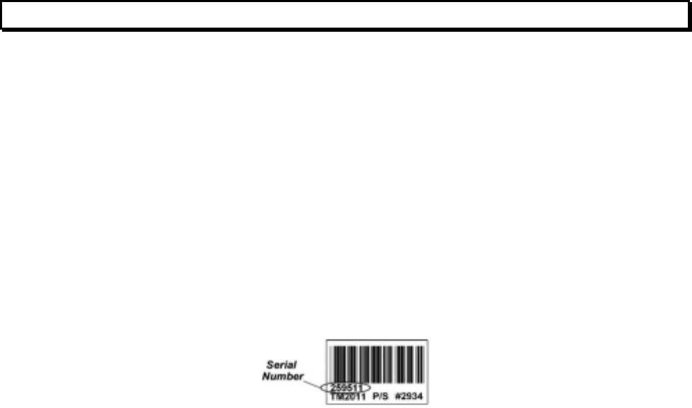
4.2 Service Policies: How to Return an Item for Service:
Before returning any item for service, an R.M.A. (Returned Material Authorization) number must be assigned
by WaveCom. A unique R.M.A. number will be assigned for each item being returned. When requesting an
R.M.A. number, please be prepared to provide the model, WaveCom serial number, original invoice number,
your purchase order number and an adequate fault description. The serial number of a unit can be found on a
barcode label similar to the one pictured below. R.M.A. service is available Monday to Friday from 8:30 a.m.
to 4:30 p.m. CST (statutory holidays excepted).
To obtain an R.M.A. number you may:
Call: (306) 955-7075, press ‘0’ for Operator, or ‘3’ for Service Dept.
Fax: (306) 384-0086 — Attention: R.M.A. Request
Email: support@WaveCom.ca
Once an R.M.A. number has been assigned, please refer to it in all correspondence and make certain that all
applicable R.M.A. numbers are clearly marked on the outside of each package being returned. You must also
ensure that each product is shipped to WaveCom in its original shipping container (or equivalent) via Prepaid
carrier, with appropriate insurance and customs documentation (where required). WaveCom will not accept
collect shipments, damaged shipments or shipments unaccompanied by an R.M.A. number.
For items still under Warranty – Items will be returned from WaveCom Electronics Inc. to its customer via
prepaid ground carrier. The customer is responsible for any additional costs incurred, including custom
clearance and duties. Any alternate means of shipment must be requested by the customer and will be
subject to additional charges.
For items no longer under Warranty – Items will be returned from WaveCom Electronics Inc. to its
customer via prepaid ground carrier at the customer’s expense. The customer is responsible for any
additional costs incurred, including custom clearance and duties. Any alternate means of shipment must be
requested by the customer and will be subject to additional charges.
Shipping Instructions will be provided by the repair center when the RMA number is sent to the
customer.
WaveCom Electronics Inc
TR2126SE Manual; ml_tr2126se_04 (May 2003)
Approved: C.H.
16
4.3 Repair Charges and Warranty Exemptions
Items returned beyond the warranty period or items that do not qualify for warranty service are subject to
additional out-of-warranty repair charges. Descriptions of these charges and warranty exemptions are below:
1) Repair turnaround time is typically 5-14 business days after receipt of the item at WaveCom. A Flat Rate
Repair Charge will apply to all out-of-warranty items. Flat Rate Repair Charges are subject to change
without notice.
2) Any faults due to customer error (ie - incorrect set-up or configuration settings) are subject to the current
Test Fee and will be exempt from warranty.
3) Items returned with inadequate fault descriptions are subject to the current Test Fee and are
exempt from warranty.
4) In the event that no fault is found, the item is subject to the current Test Fee and will be
exempt from warranty.
5) Any product exhibiting external damage (either from shipping, improper handling or use) will be subject to
inspection. If said damages are determined to be the cause of failure, the item will be exempt from
warranty.
All repairs to correct the external damage are subject to Time & Materials Charges (parts and labor at
current rates).
6) Items with damage caused by unauthorized repairs or by external devices are subject to current out-of-
warranty Flat Rate Repair Charges and are exempt from warranty.
7) All products returned for Factory Optioning are subject to the applicable current Option Charge plus Test
Fee. Factory-optioned products carry the balance of the original warranty or a 90 day warranty, whichever
is greater.
All out-of-warranty repairs must be approved by the customer in writing. No repairs will be made until the
customer’s Purchase Order or Out-Of-Warranty Repair Authorization is received.


150 Cardinal Place
Saskatoon, Saskatchewan
S7L 6H7
Canada
Tel: (306) 955-7075
Fax: (306) 955-9919
www.WaveCom.ca
sales@WaveCom.ca