Vecima Networks TR700B TR700B UHF Transceiver User Manual TR700B Manual
Vecima Networks Inc. TR700B UHF Transceiver TR700B Manual
UserManual.wiki
>
Vecima Networks
>
TR700B User Manual
Users guide
Navigation menu
Upload a User Manual
Namespaces
Wiki Guide
HTML
PDF
Info
Views
User Manual
Discussion / Help
Navigation

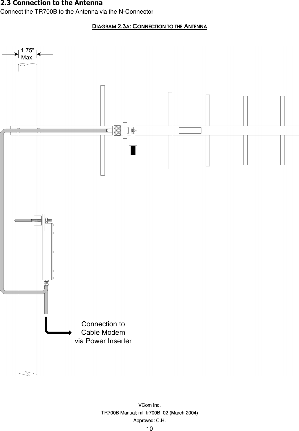
![VCom Inc. TR700B Manual; ml_tr700B_02 (March 2004) Approved: C.H. 9 %&Mount the antenna according to the manufacturer’s instructions. The TR700B is intended for use with planar arrays and Yagi antennas. Please consult table 2.2B for further information. Table 2.2B: Antenna List Transceiver Power Antenna Type Antenna Gain [Watts] [dBm] [dBi] 0.25 +24 Yagi 10 dBi 0.25 +24 Flat planar array 9 dBi 0.25 +24 Window mount planar array 7 dBi Included with the TR700B unit is a self-adhesive label for application to the antenna. To operate the TR700B in compliance with FCC regulations, you must apply the included label to the antenna. Peel off the protective backing from the label and affix it to the antenna such that the label is readable from a distance of 5 feet. DIAGRAM 2.2C: APPLYING THE SELF-ADHESIVE LABEL ](https://usermanual.wiki/Vecima-Networks/TR700B/User-Guide-409948-Page-9.png)