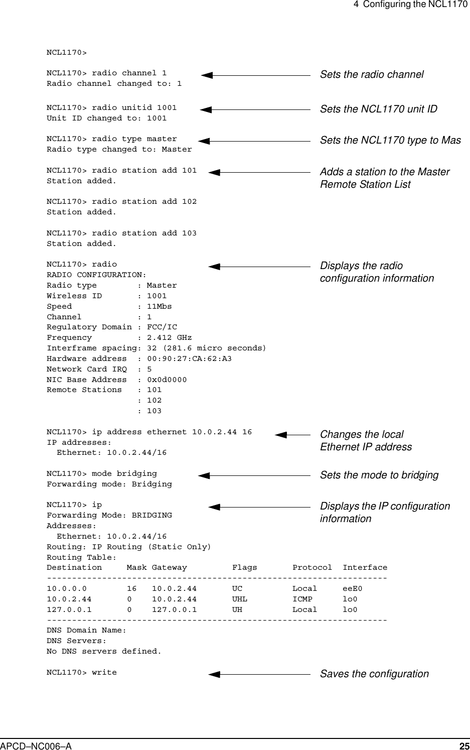
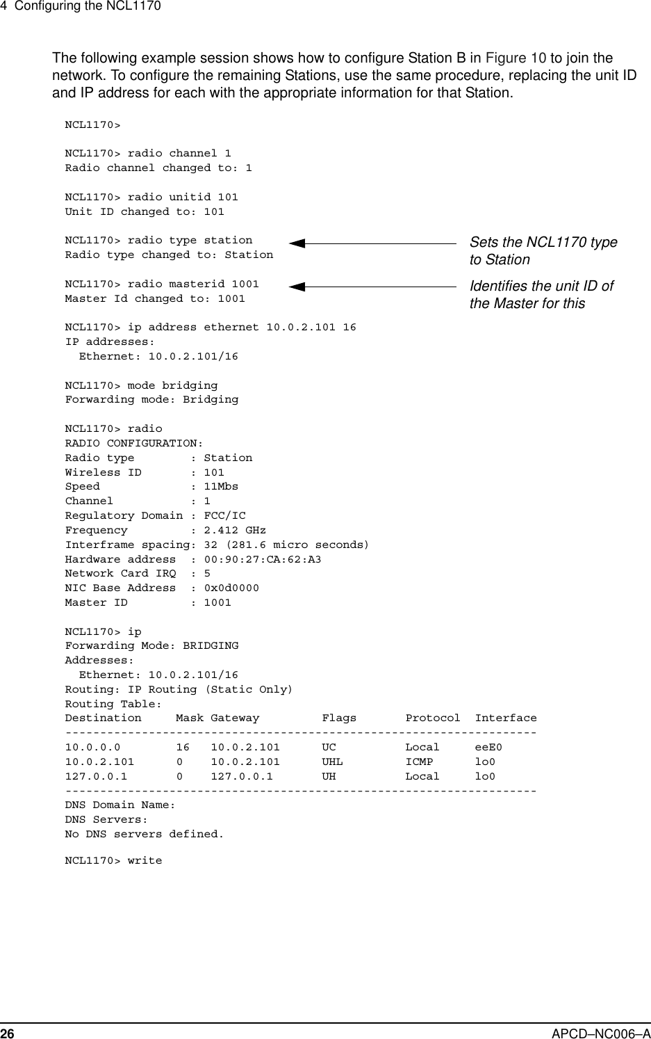
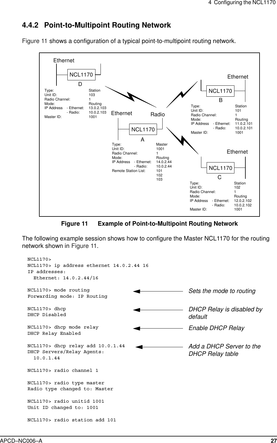
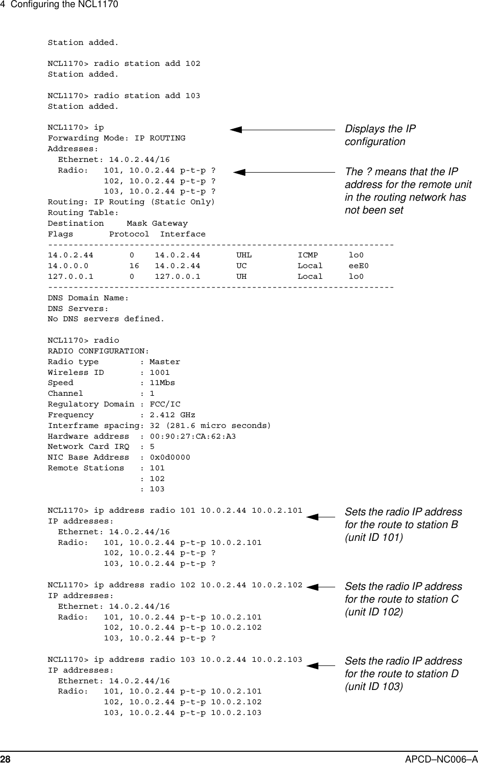
Vecima Networks WRM2000 Wireless bridge/router model NCL1170 User Manual NCL1155 User Manual
Vecima Networks Inc. Wireless bridge/router model NCL1170 NCL1155 User Manual
UserManual.wiki
>
Vecima Networks
>
WRM2000 User Manual
>
Users manual
Contents
1.
Users manual
2.
Revised manual
Users manual
Navigation menu
Upload a User Manual
Namespaces
Wiki Guide
HTML
PDF
Info
Views
User Manual
Discussion / Help
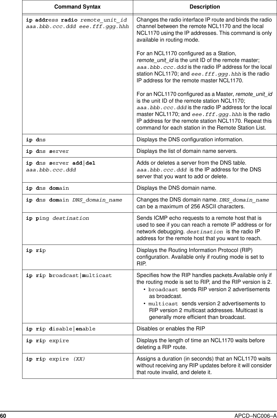
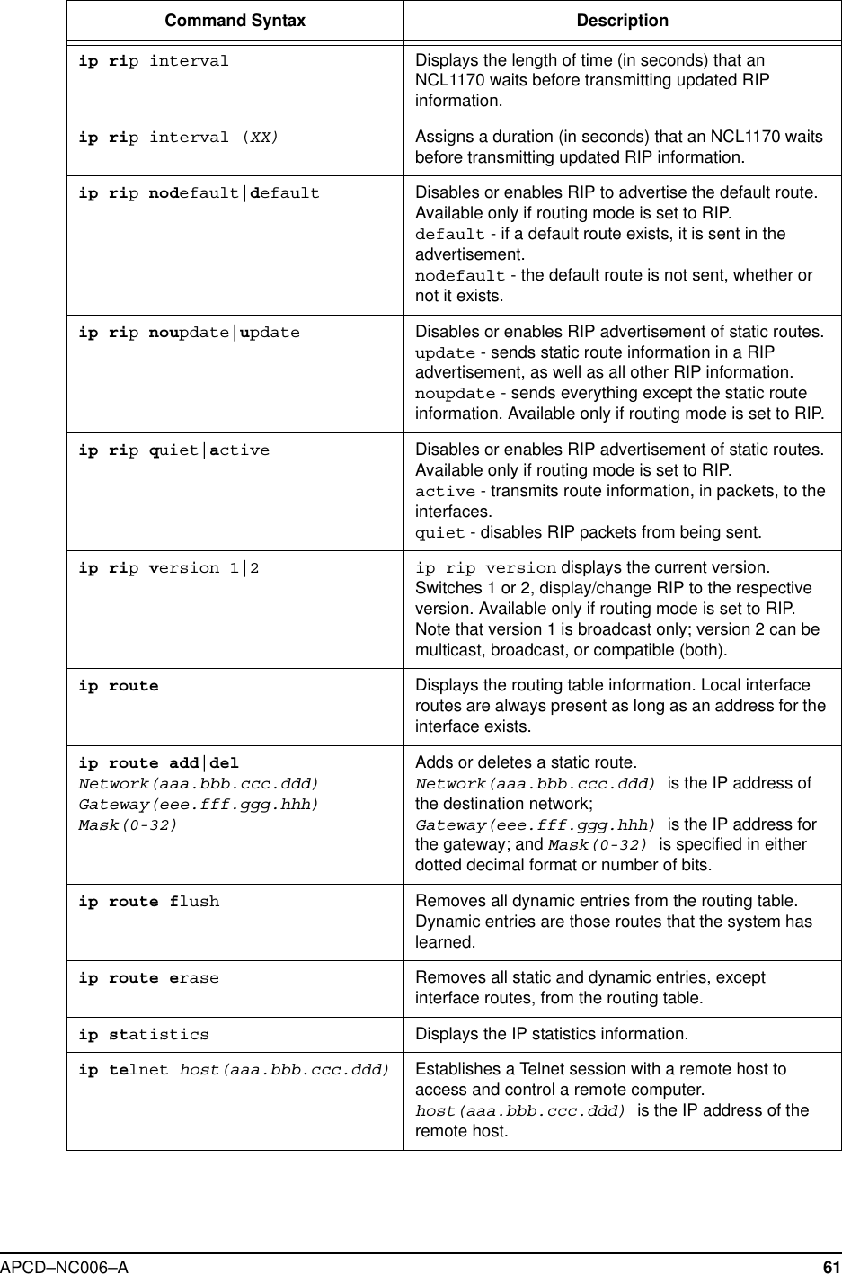
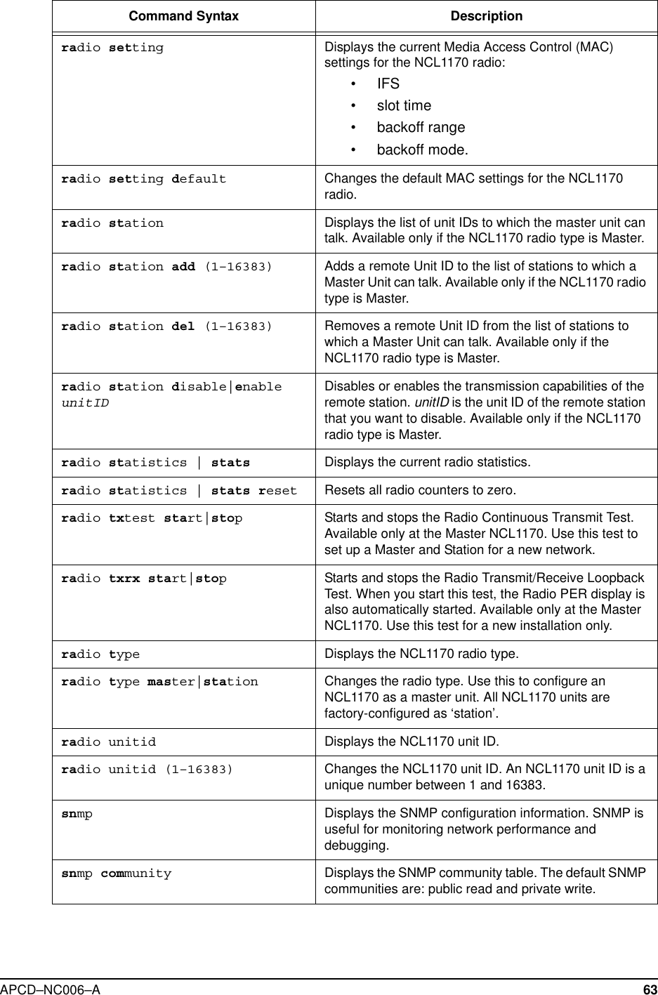
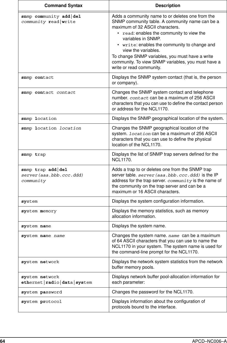
Navigation


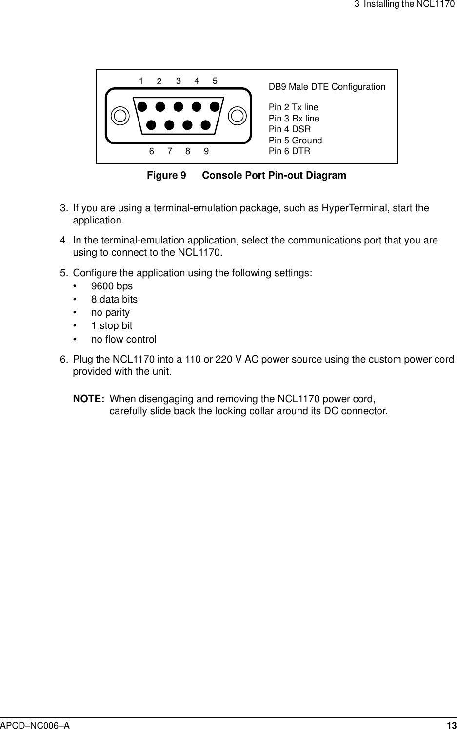

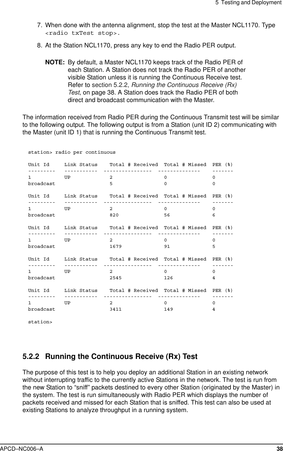
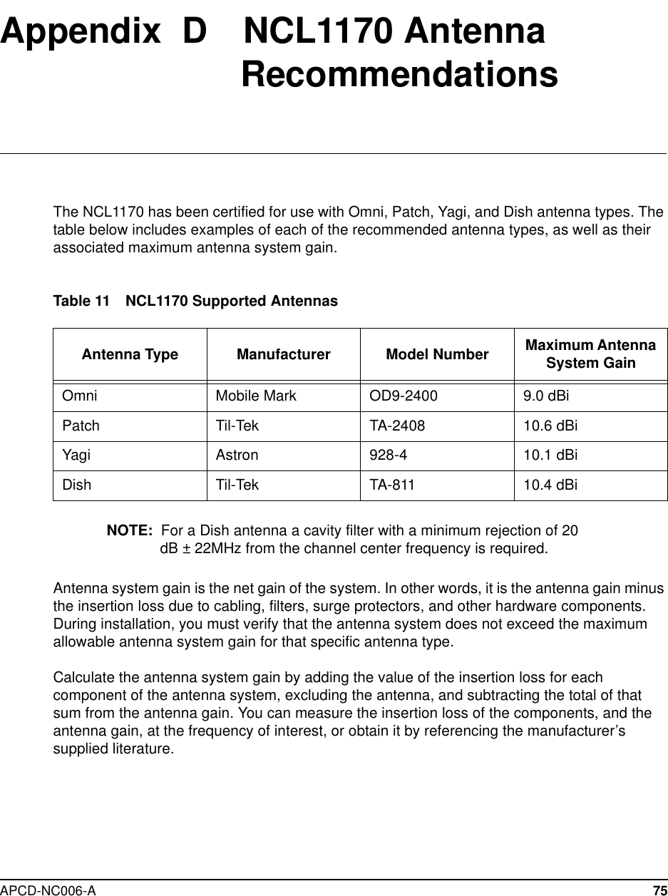
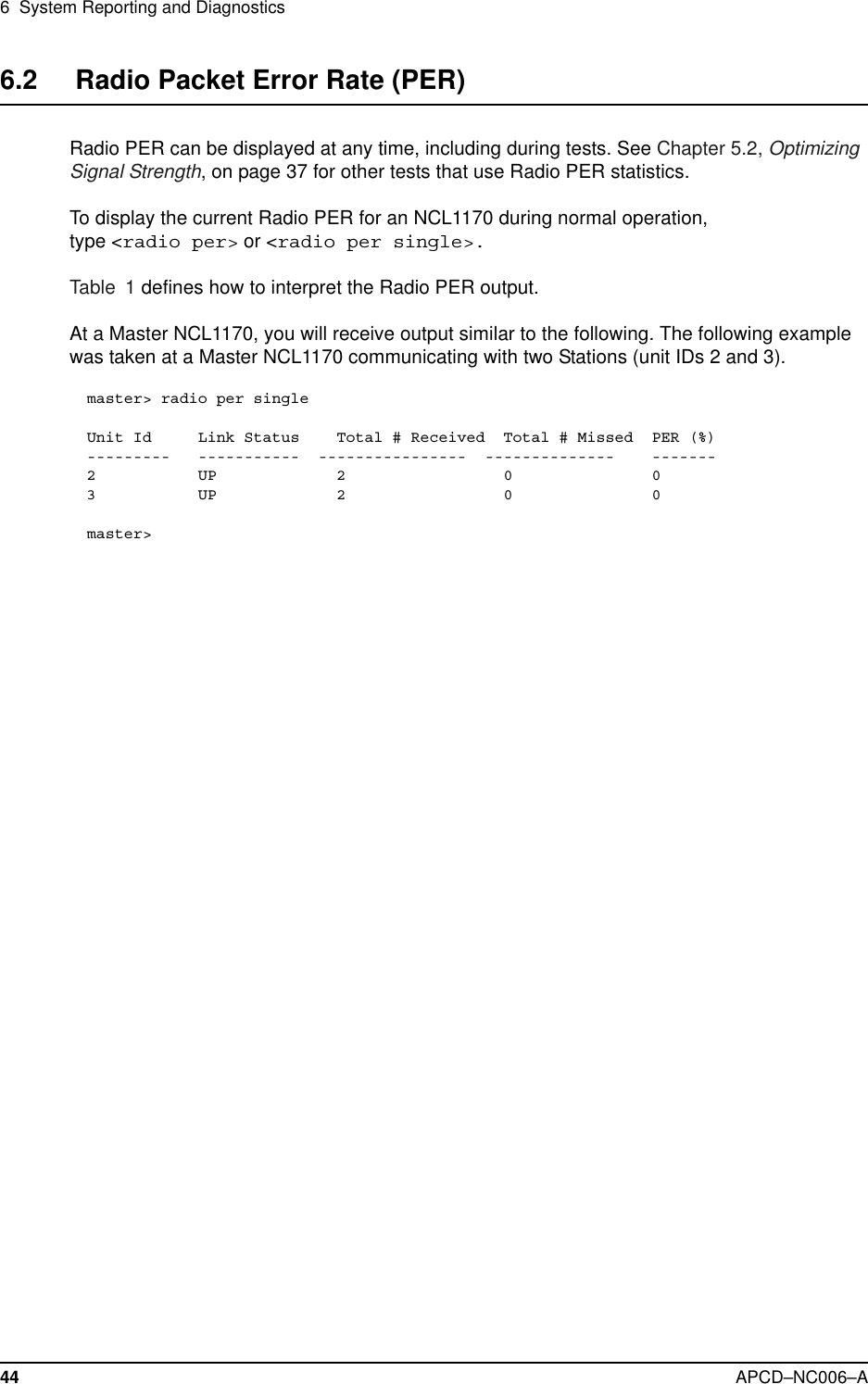
![5 Testing and DeploymentAPCD–NC006–A 40Unit Id Link Status Total # Received Total # Missed PER (%)--------- ----------- ---------------- -------------- -------1UP 1 0 0broadcast 515 0 03UP 1 0 0Unit Id Link Status Total # Received Total # Missed PER (%)--------- ----------- ---------------- -------------- -------1UP 1 0 0broadcast 518 0 03UP 1 0 0[Radio Rx Test On]station> radio rxtest stopstation>](https://usermanual.wiki/Vecima-Networks/WRM2000.Users-manual/User-Guide-141944-Page-54.png)
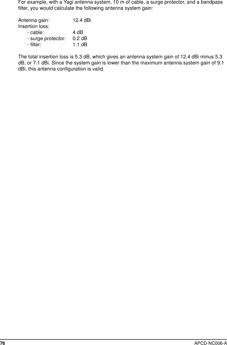
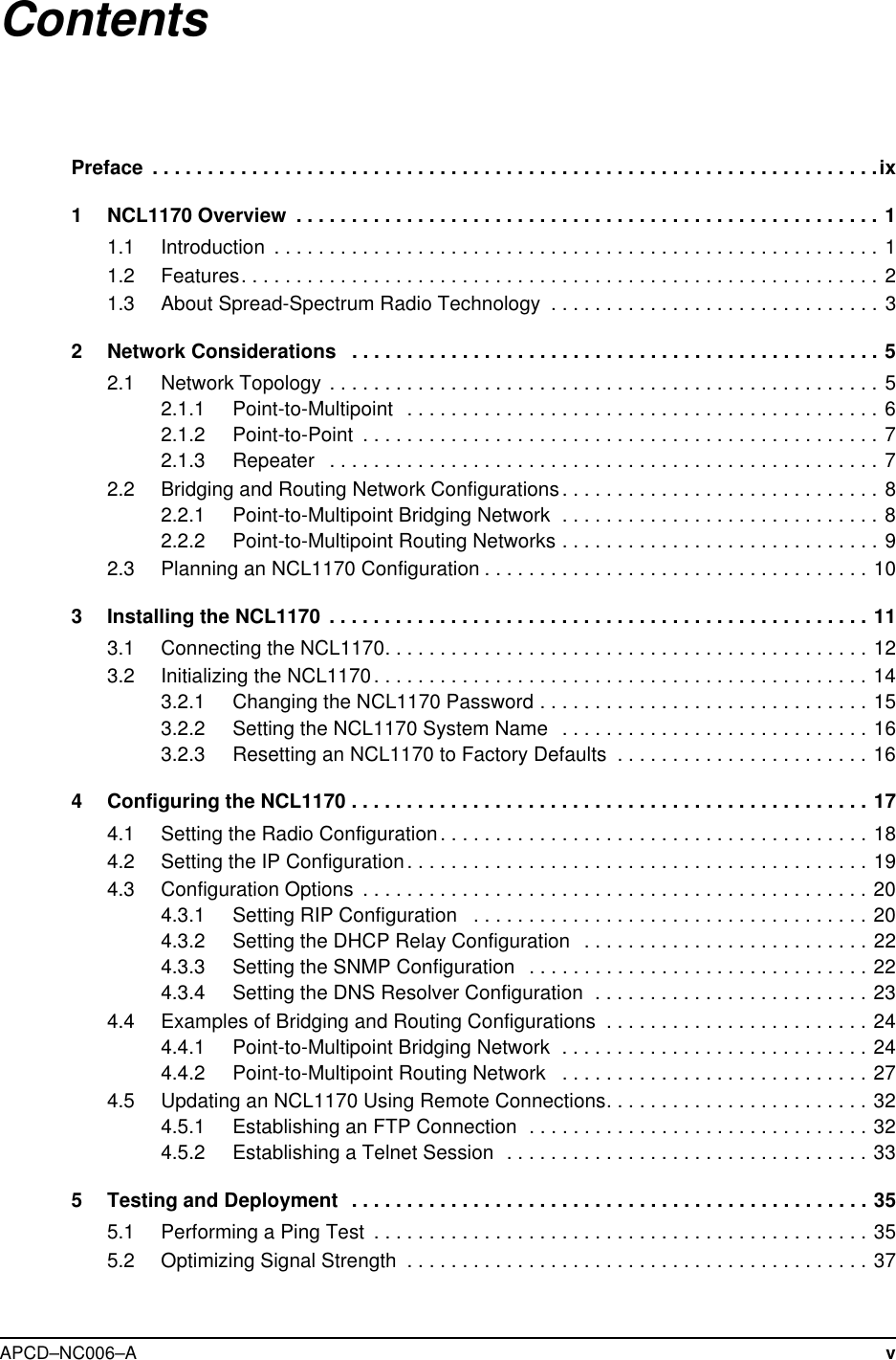
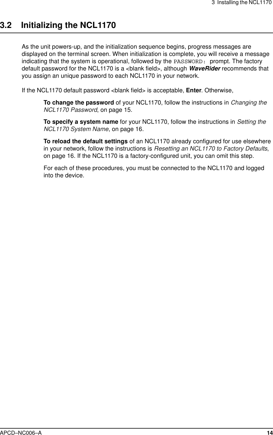
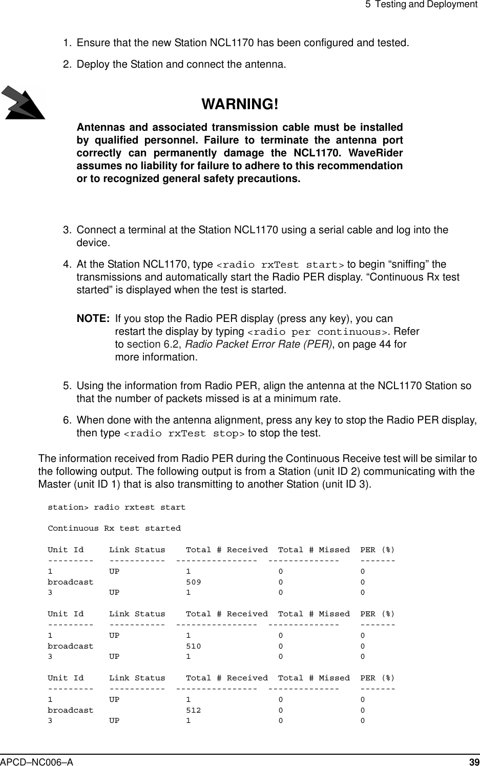
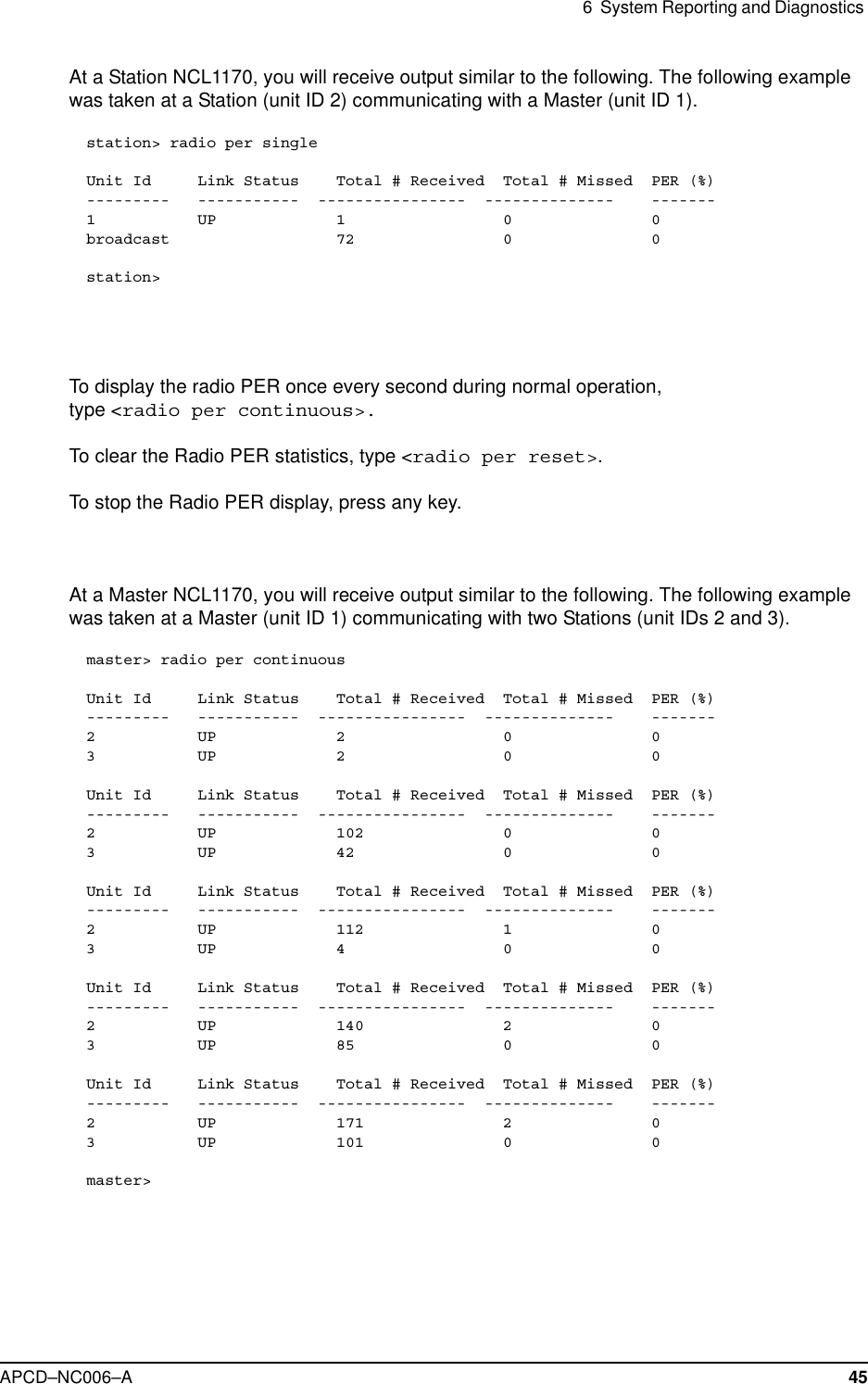
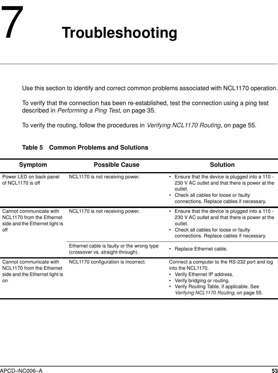
![5 Testing and DeploymentAPCD–NC006–A 42The information received from Radio PER during the Transmit/Receive Loopback test will besimilar to the following output. The following output is from a Master (unit ID 1) communicatingwith two Stations (unit IDs 2 and 3).master> radio txrx startTx/Rx test startedUnit Id Link Status Total # Received Total # Missed PER (%)--------- ----------- ---------------- -------------- -------2UP 9 0 03UP 5 0 0Unit Id Link Status Total # Received Total # Missed PER (%)--------- ----------- ---------------- -------------- -------2 UP 827 53 63 UP 820 56 6Unit Id Link Status Total # Received Total # Missed PER (%)--------- ----------- ---------------- -------------- -------2 UP 1689 85 43 UP 1679 91 5Unit Id Link Status Total # Received Total # Missed PER (%)--------- ----------- ---------------- -------------- -------2 UP 2566 109 43 UP 2545 126 4Unit Id Link Status Total # Received Total # Missed PER (%)--------- ----------- ---------------- -------------- -------2 UP 3423 141 33 UP 3411 149 4[Radio TxRx Test On]master> radio txrx stopmaster>](https://usermanual.wiki/Vecima-Networks/WRM2000.Users-manual/User-Guide-141944-Page-56.png)

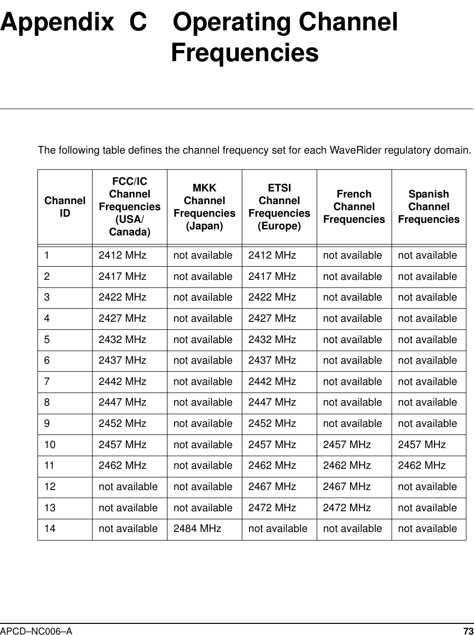
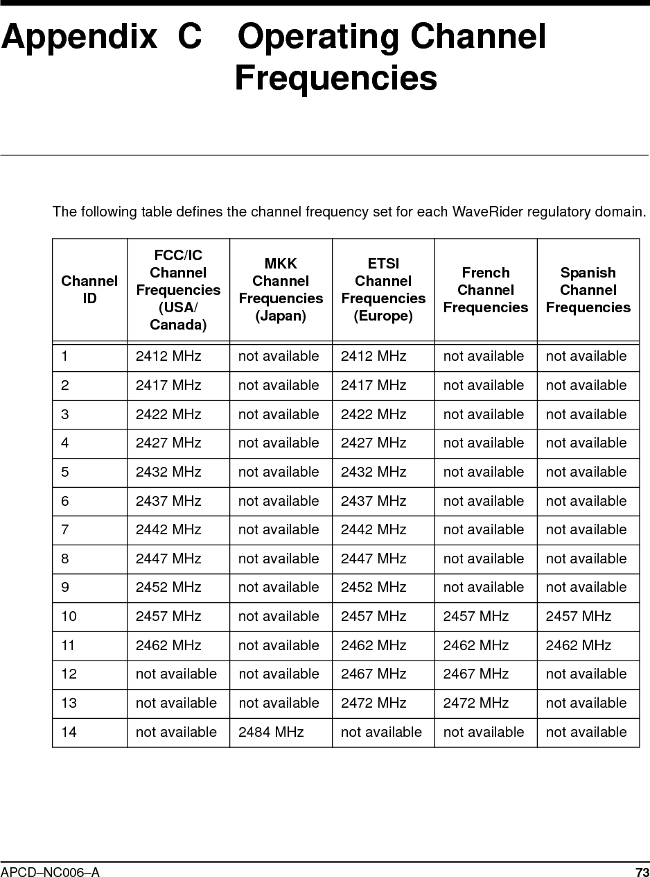
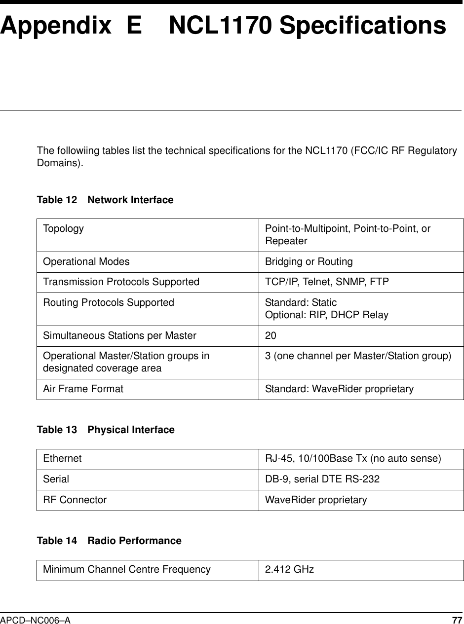
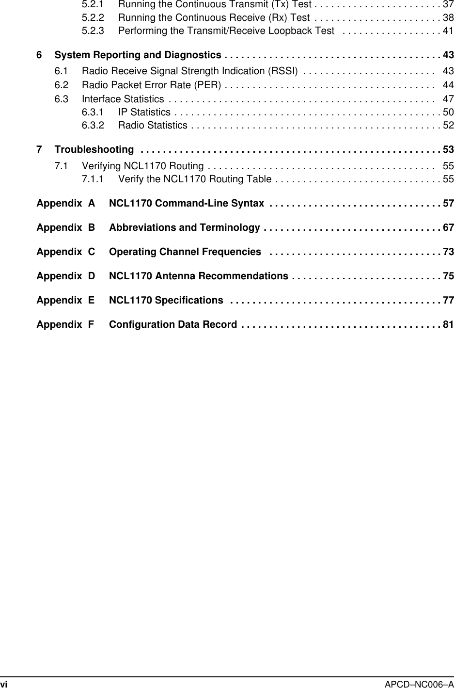
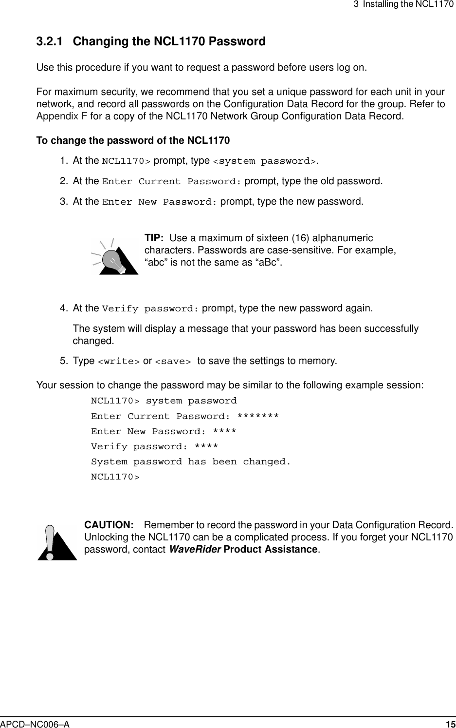
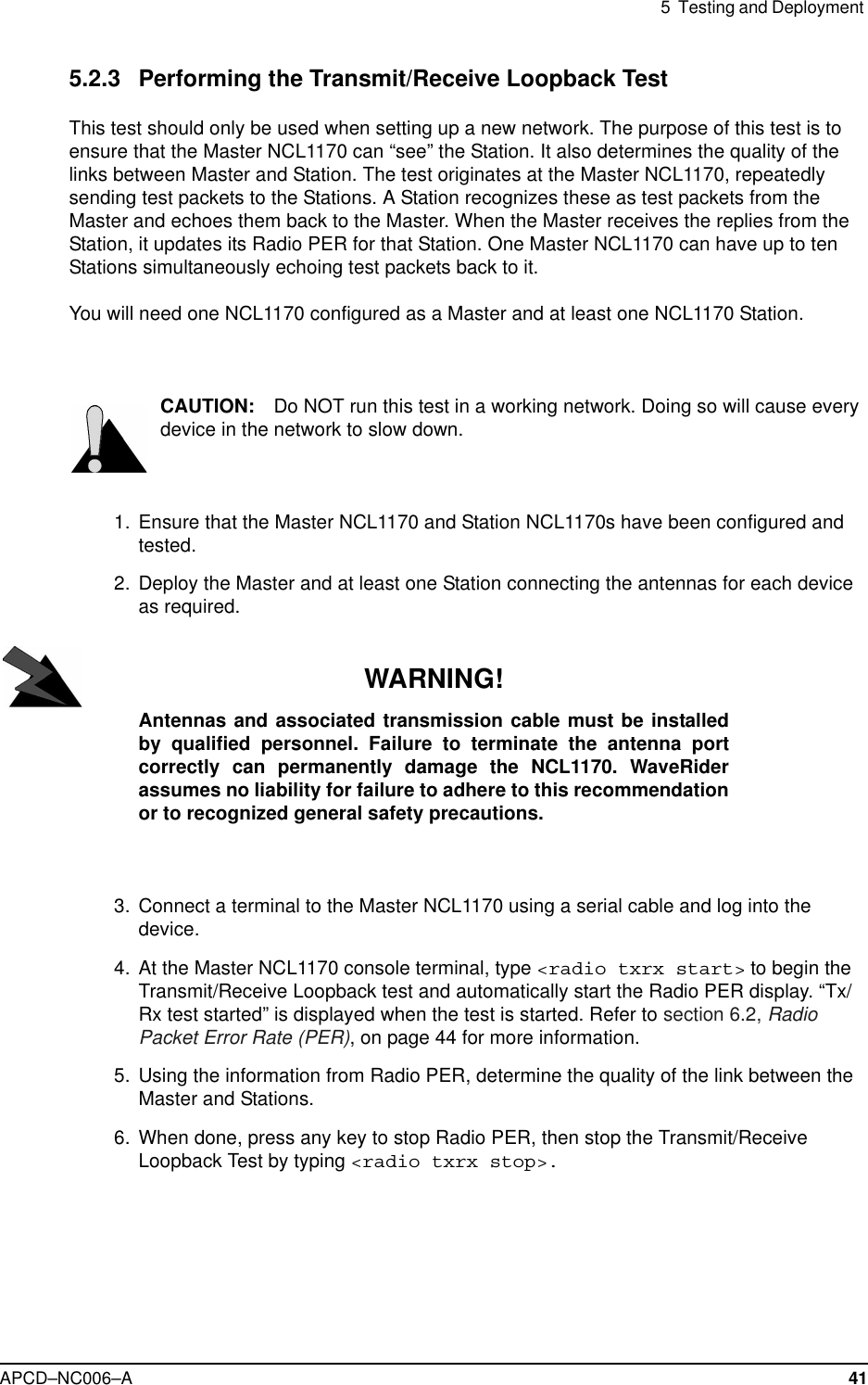
![APCD–NC006–A 57Appendix A NCL1170 Command-LineSyntaxThe NCL1170 can be configured using the commands listed in Table 8.Table 6 shows the typographical conventions used to represent command-line syntax. PressENTER after typing a command to execute the command.Table 7 provides a list of shortcuts and methods to get help on commands.Table 6 NCL1170 Command-Line Syntax ConventionsConvention Use Examples<monospacedfont>Indicates that you must type the text inside theangle brackets, not the angle brackets.<ip route>ENTER Indicates a keyboard key press. A plus sign (+)indicates key combinations. For example, forCTRL+U, press and hold down the CTRL key,then press the U key.ENTERESCCTRL+Uitalic Specifies a variable name or other informationthat you must replace with a real name orvalue.ip address ethernetipaddressbold characters Indicates the shortcut characters for acommand.<radio channel> can alsobe typed as <ra ch>[] Indicates optional items. Do not type thebrackets as part of the command.ip address[ethernet|radio]|Separates two mutually exclusive choices in acommand. Type one choice and do not typethe vertical bar.interface|if() Encloses a range of values from which you canchoose a value.radio channel (1-15)](https://usermanual.wiki/Vecima-Networks/WRM2000.Users-manual/User-Guide-141944-Page-71.png)
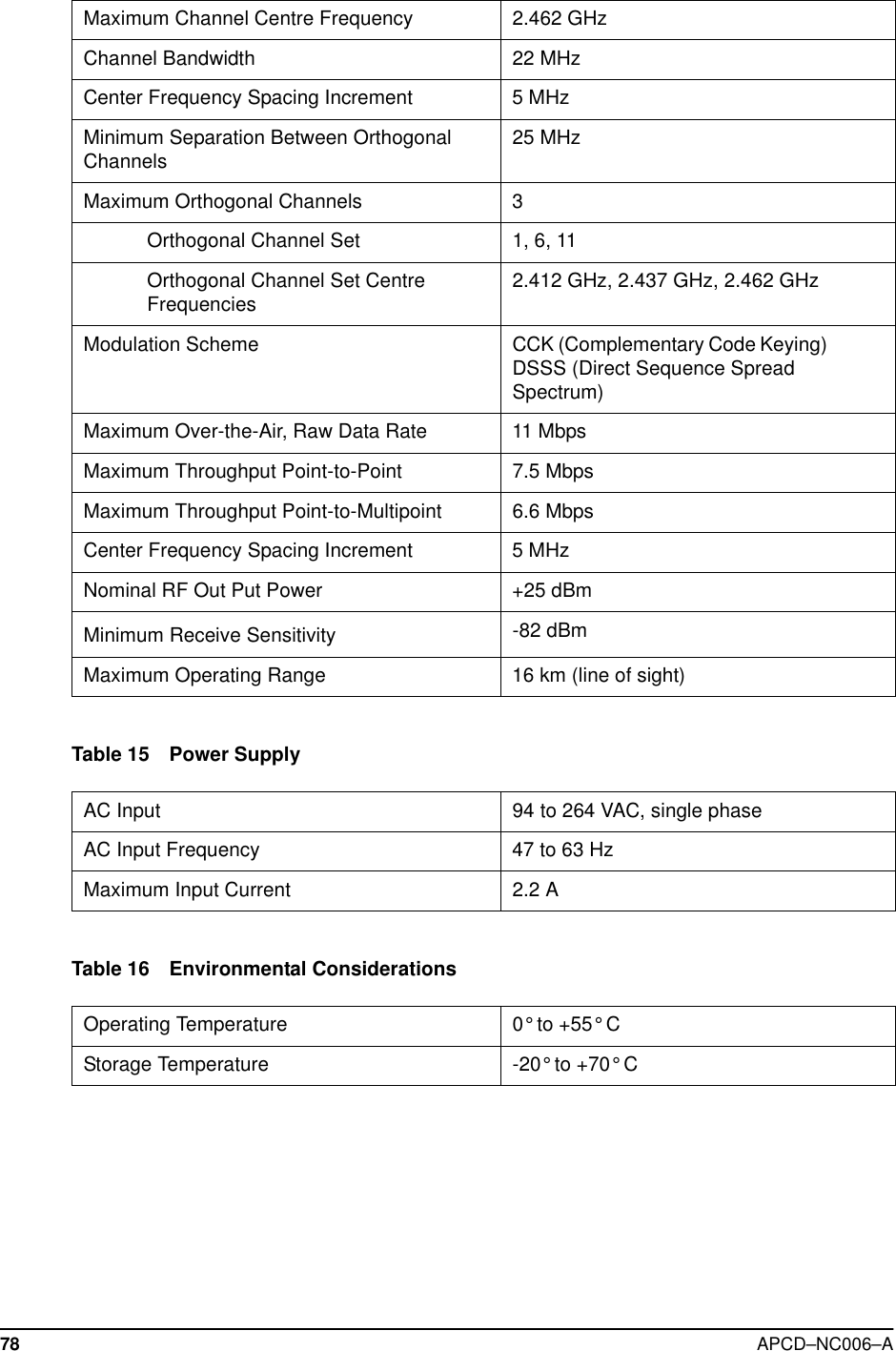
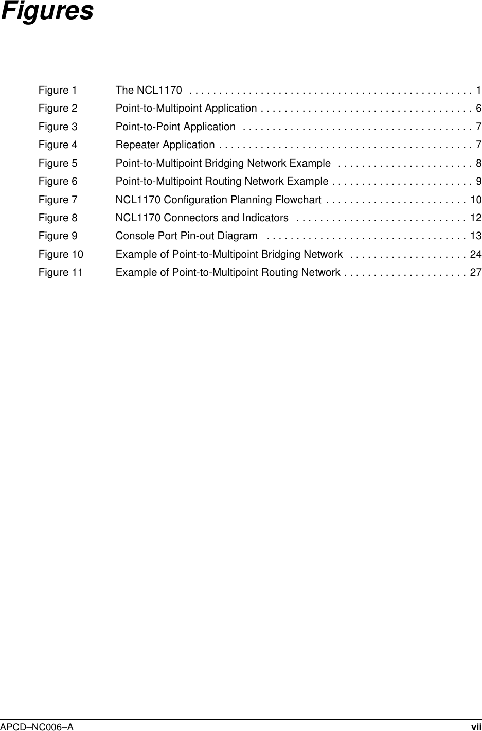
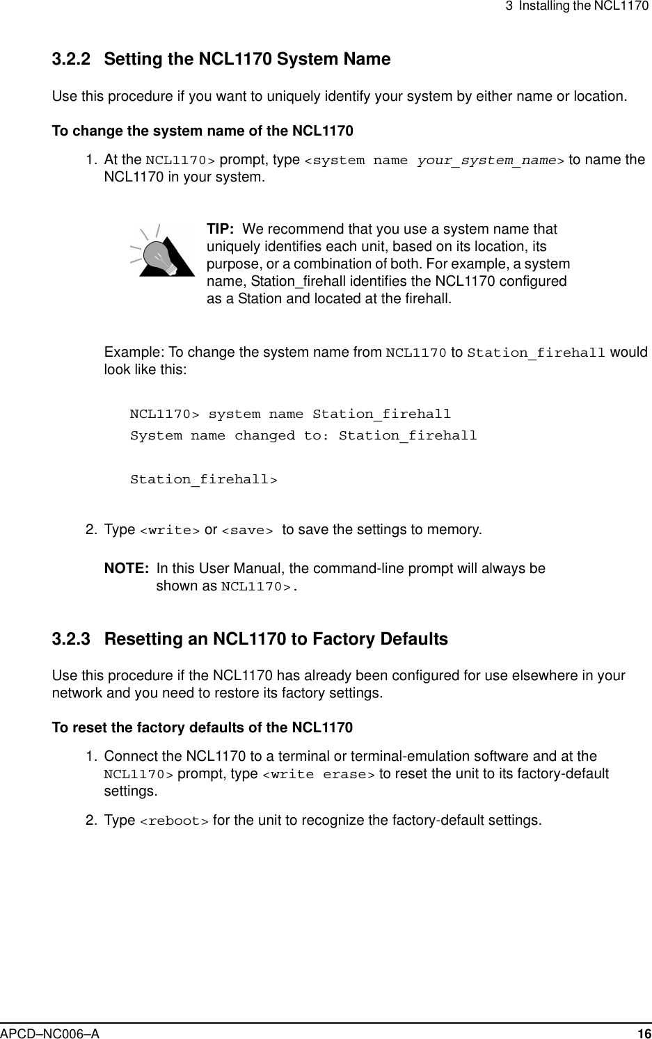
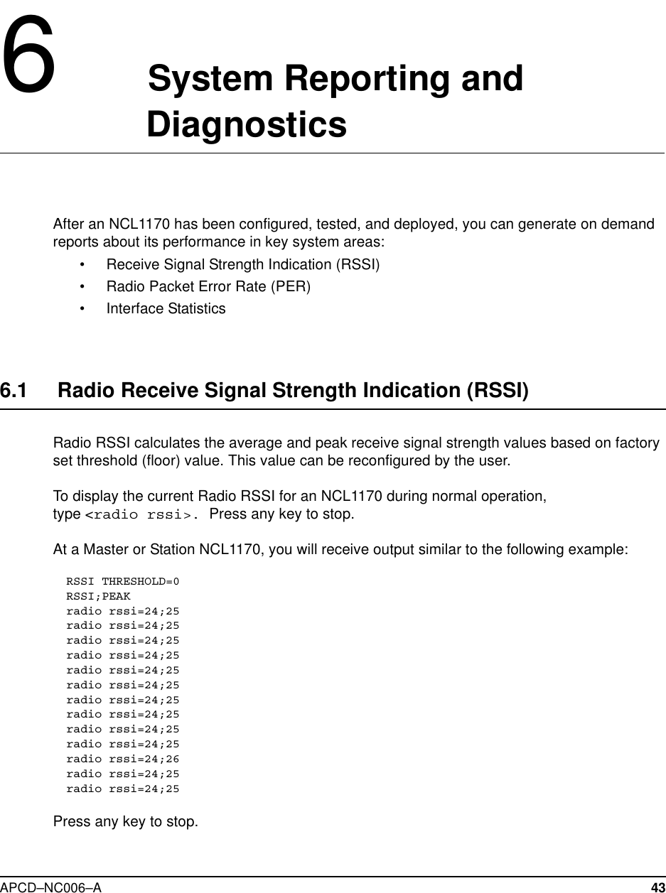
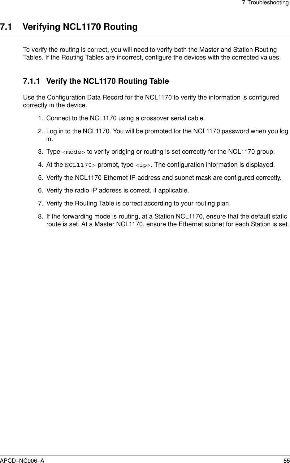
![58 APCD–NC006–ATable 7 Command-Line Shortcuts and Getting HelpSubnet MasksWhere a command requires you to enter a subnet mask, you can do one of the following:• Enter it as a range, which is the number of bits (0-32 are valid) in the subnet mask.• Do not enter it, and let the NCL1170 decide what value to use. Note that the NCL1170does not necessarily pick the correct subnet mask.Table 8 NCL1170 Command-line Syntax DescriptionsType To do this...?display the names of the root commands.[command_name]? display the syntax for a command.help display all the commands, their subcommands and theparameters and options for each command.help [command_name]display the parameters and options for the command.!! repeat the last command that was executed.ESC cancel the command you are typing.Command Syntax Descriptionarp Displays the Address Resolution Protocol (ARP)configuration information.arp flush Removes the temporary ARP table entries from theARP table.arp add aaa.bbb.ccc.dddaa:bb:cc:dd:ee:ffAdds an entry to the ARP table. aaa.bbb.ccc.ddd isthe IP address of the entry that you want to add.aa:bb:cc:dd:ee:ff is the MAC address associatedwith the IP address.arp del aaa.bbb.ccc.ddd Deletes a specified entry from the ARP table.aaa.bbb.ccc.ddd is the IP address of the entry thatyou want to delete.bridge statistics Displays the bridge statistics (frames in, frames out,etc.). Only available in bridging mode.bridge table Displays the bridge table entries. Only available inbridging mode.bridge table flush Removes the learned entries from the bridge table. Onlyavailable in bridging mode.](https://usermanual.wiki/Vecima-Networks/WRM2000.Users-manual/User-Guide-141944-Page-72.png)
![APCD–NC006–A 59bridge table timeout Sets the time-out value for entries in the bridge table. Ifthe NCL1170 receives no packet from the specifiedentry's address during the time-out period you set (forexample, 15 s), then it clears the address from the table.Valid times are 10 to 1 000 000 s; the default is 300 s.Only available in bridging mode.dhcp mode [none|relay] Sets the NCL1170 to use Dynamic Host ConfigurationProtocol (DHCP).• none - disables DHCP Relay.• relay - enables DHCP Relay.Available only if the mode is set to routing.dhcp relay [add|deleteip_address]Adds or removes the IP address of a Dynamic HostConfiguration Protocol (DHCP) server. Available only ifthe mode is set to routing and DHCP mode is set toRelay.interface|if statistics Displays configuration information and statistics for allinterfaces.interface|if statisticsethernet|radio|loopbackDisplays configuration information and statistics foreach interface: Ethernet, radio, or loopback.interface|if reset Resets the statistics for all interfaces.interface|if resetethernet|radio|loopbackResets the statistics for the specified interface.ip Displays the IP configuration information.ip address Displays the IP addresses for the Ethernet and radiointerface. In bridging mode, the IP address is formanagement purposes only. An IP address is notrequired to perform bridge functions. When in Bridgingmode, if you assign an IP address to the NCL1170, youonly need to assign it to the Ethernet interface, becausethe radio and Ethernet are considered as one interface.In routing mode, you must configure both addresses.ip address ethernetaaa.bbb.ccc.ddd [subnet mask]Changes the IP address for the Ethernet interface forrouting or bridging. aaa.bbb.ccc.ddd is the IP addressfor the Ethernet interface and [subnet mask] isspecified in either dotted decimal format or number ofbits.Command Syntax Description](https://usermanual.wiki/Vecima-Networks/WRM2000.Users-manual/User-Guide-141944-Page-73.png)
![62 APCD–NC006–Aip traceroutedestination(aaa.bbb.ccc.ddd)Displays the route that the packets take to a remotedestination. destination(aaa.bbb.ccc.ddd) isthe IP address of the remote destination. The maximumis 30 hops. An asterisk (*) represents each unsuccessfultry. For example, 1 * * *. Press any key to stop the iptraceroute output.mode Displays the forwarding mode: Bridging or IP Routing.mode bridging|routing Changes the forwarding mode.bridging: connects two networks on the same subnet(they have the same subnet address).routing: connects two networks on different subnets.radio Displays the radio configuration information.radio channel Displays the radio channel.radio channel (1–14) Changes the radio channel.radio disable|enable Disables or enables the NCL1170 radio transmissioncapabilities. The NCL1170 is factory-configured asdisabled to prevent accidental damage should it bepowered up without an antenna or load connected.radio masterID Displays the Master Unit ID to which the NCL1170belongs. Available only if the NCL1170 radio type isStation.radio masterID (1–16383) Changes the Master Unit ID to which the NCL1170belongs. Available only if the NCL1170 radio type isStation.radio per[single|continuous|reset]Displays or resets the cumulative radio packet error ratestatistics to the screen. This command is availableduring tests and normal operation.•single displays the current statistics.•continuous displays the statistics every onesecond.•reset resets the calculations.radio reset Forces the NCL1170 radio to reset. If you reset theNCL1170 radio instead of shutting down, the statisticswill not be lost.radio rssi When serially connected to the NCL1170, displayschanges in the average and peak receive signalstrength every half second.radio rssi threshold Changes the threshold (floor) value used to calculatethe average receive signal strength.radio rxtest start|stopStarts and stops the Radio Continuous Receive Test.When you start this test, the Radio PER display is alsoautomatically started. Available only at the StationNCL1170. Use this test to deploy a new StationNCL1170 in an existing network.Command Syntax Description](https://usermanual.wiki/Vecima-Networks/WRM2000.Users-manual/User-Guide-141944-Page-76.png)
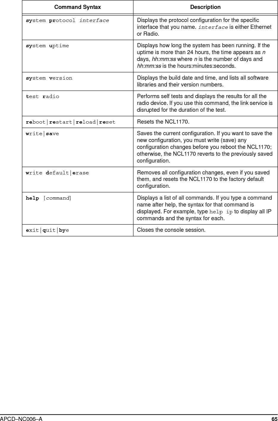
![APCD–NC006–A 65system protocol interface Displays the protocol configuration for the specificinterface that you name. interface is either Ethernetor Radio.system uptime Displays how long the system has been running. If theuptime is more than 24 hours, the time appears as ndays, hh:mm:ss where nis the number of days andhh:mm:ss is the hours:minutes:seconds.system version Displays the build date and time, and lists all softwarelibraries and their version numbers.test radio Performs self tests and displays the results for all theradio device. If you use this command, the link service isdisrupted for the duration of the test.reboot|restart|reload|reset Resets the NCL1170.write|save Saves the current configuration. If you want to save thenew configuration, you must write (save) anyconfiguration changes before you reboot the NCL1170;otherwise, the NCL1170 reverts to the previously savedconfiguration.write default|erase Removes all configuration changes, even if you savedthem, and resets the NCL1170 to the factory defaultconfiguration.help [command]Displays a list of all commands. If you type a commandname after help, the syntax for that command isdisplayed. For example, type help ip to display all IPcommands and the syntax for each.exit|quit|byeCloses the console session.Command Syntax Description](https://usermanual.wiki/Vecima-Networks/WRM2000.Users-manual/User-Guide-141944-Page-79.png)