Vecima Networks WRM3200 CCU3200 User Manual LMS3200 R2 UserGuide
Vecima Networks Inc. CCU3200 LMS3200 R2 UserGuide
UserManual.wiki
>
Vecima Networks
>
WRM3200 User Manual
>
User guide extract 2
Contents
1.
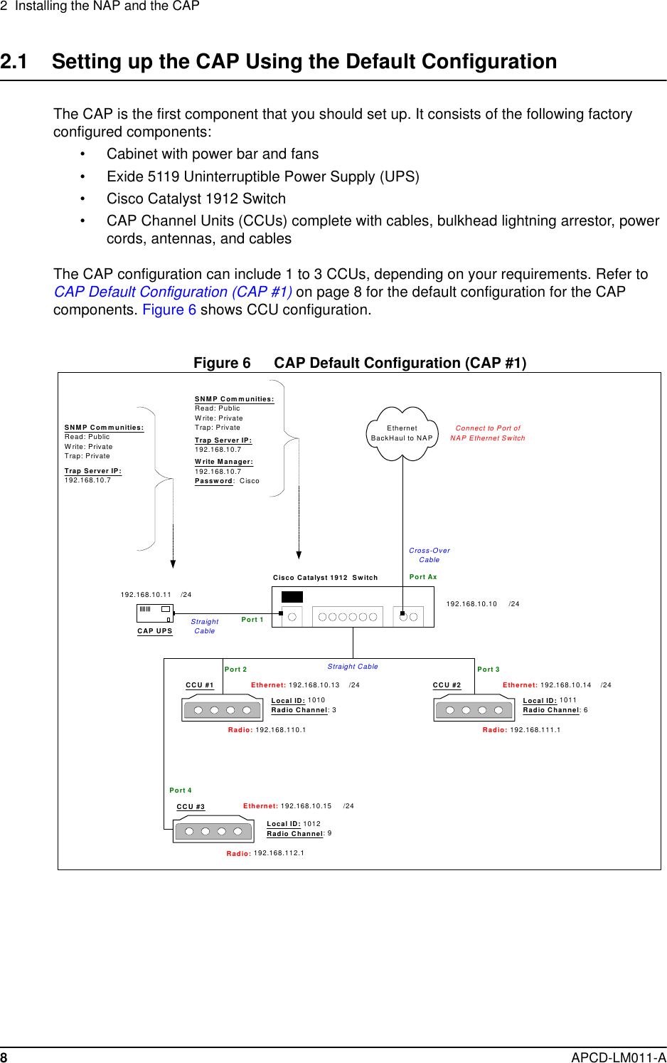
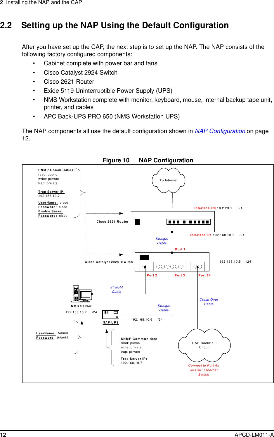
Extract from users guide
2.
Erratum to users guide
3.
User guide extract 2
4.
User Guide with corrected RF safety language
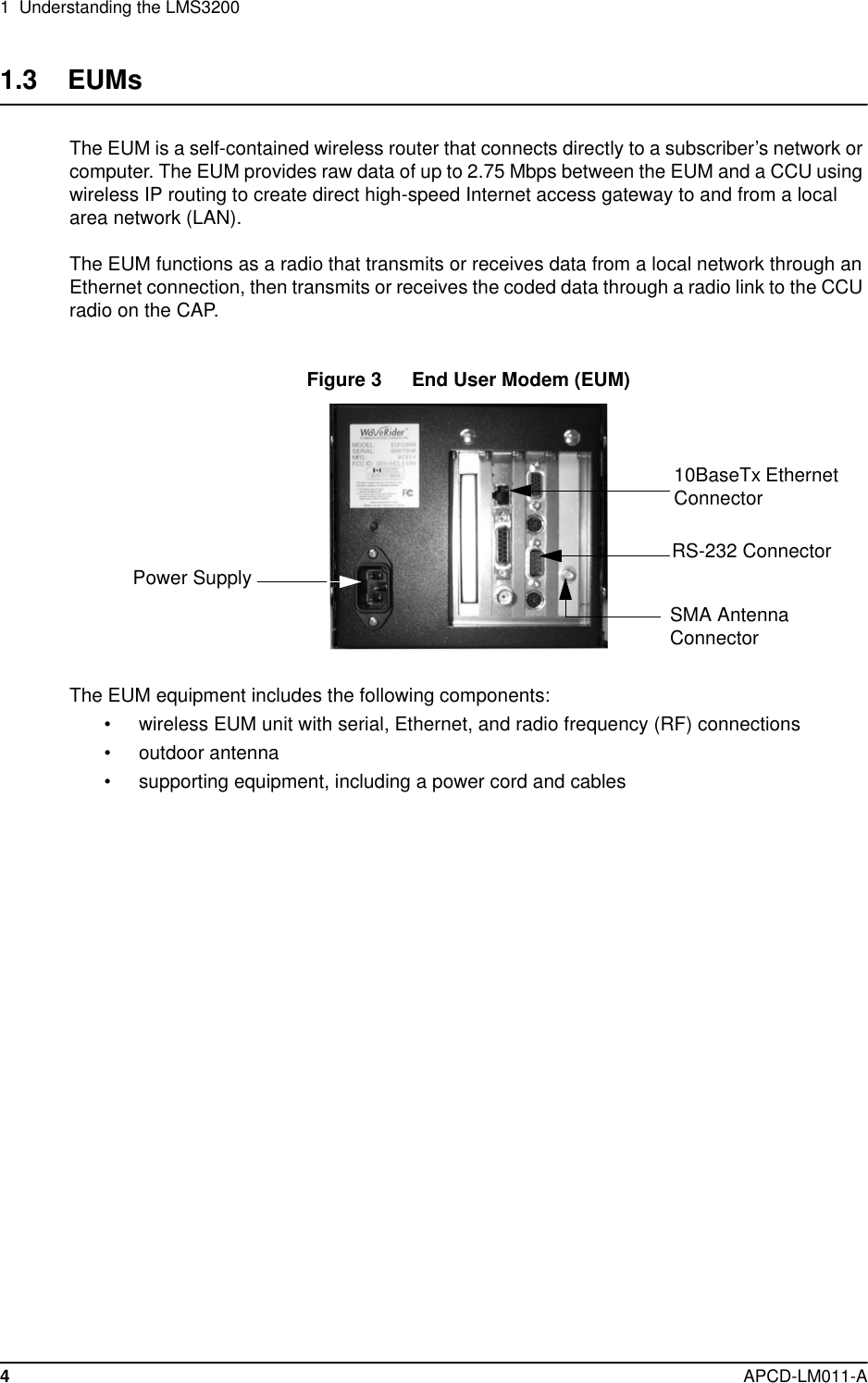
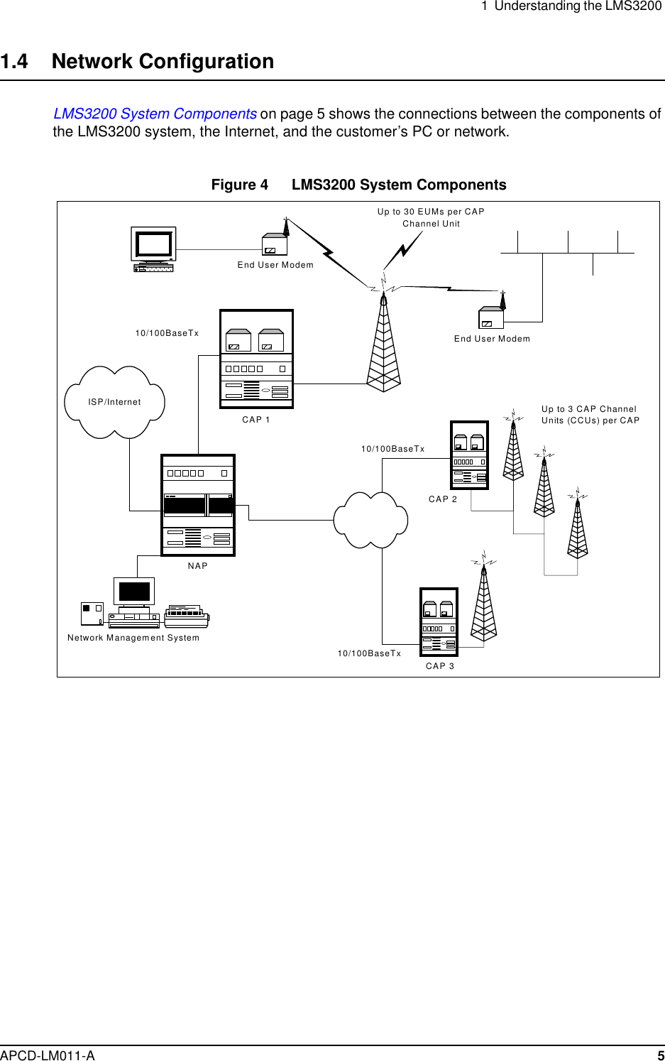
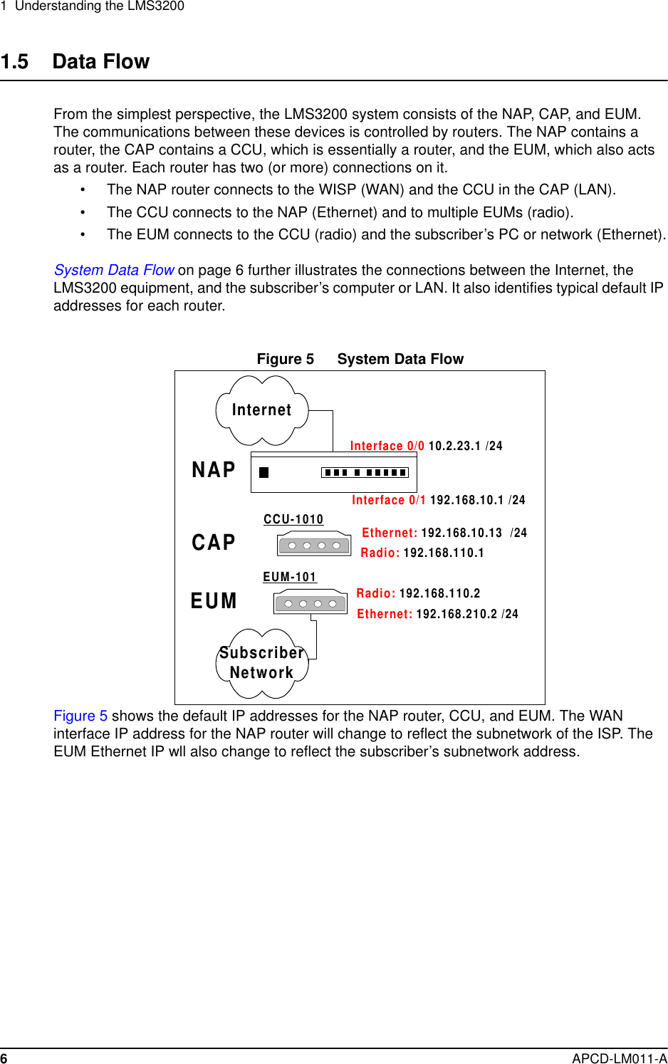
User guide extract 2
Navigation menu
Upload a User Manual
Namespaces
Wiki Guide
HTML
PDF
Info
Views
User Manual
Discussion / Help
Navigation