Vecima Networks WRM3200 CCU3200 User Manual LMS3200 R2 UserGuide
Vecima Networks Inc. CCU3200 LMS3200 R2 UserGuide
Contents
User guide extract 2

LMS3200
User Guide
Version A

WaveRider Communications Inc.
Software License Agreement
This is a legal agreement between you (either an individual or an entity) and WaveRider Communications Inc. for the use
of WaveRider computer software, hereinafter the “LICENSED SOFTWARE”.
By using the LICENSED SOFTWARE installed in this product, you acknowledge that you have read this license
agreement, understand it, and agree to be bound by its terms. You further agree that it is the full and complete
agreement between you and WaveRider Communications Inc., superseding all prior written or verbal
agreements of any kind related to the LICENSED SOFTWARE. If you do not understand or do not agree to the
terms of this agreement, you will cease using the LICENSED SOFTWARE immediately.
1 GRANT OF LICENSE—This License Agreement permits you to use one copy of the LICENSED SOFTWARE.
2. COPYRIGHT—The LICENSED SOFTWARE is owned by WaveRider Communications Inc. and is protected by
copyright laws and international treaty provisions; therefore, you must treat the LICENSED SOFTWARE like
any other copyrighted material (e.g., a book or magazine). You may not copy the written materials
accompanying the LICENSED SOFTWARE.
3. OTHER RESTRICTIONS—You may not rent or lease the LICENSED SOFTWARE. You may not reverse
engineer, decompile, or disassemble the LICENSED SOFTWARE.
4. LIMITED WARRANTY—The LICENSED SOFTWARE is provided “as is” without any warranty of any kind,
either expressed or implied, including, but not limited to, the implied warranties of merchantability and fitness
for a particular purpose. The entire risk as to the quality and performance of the LICENSED SOFTWARE is
with you, the licensee. If the LICENSED SOFTWARE is defective, you assume the risk and liability for the
entire cost of all necessary repair, service, or correction.
Some states/jurisdictions do not allow the exclusion of implied warranties, so the above exclusion
may not apply to you. This warranty gives you specific legal rights, and you may have other rights,
which vary from state/jurisdiction to state/jurisdiction.
WaveRider Communications Inc. does not warrant that the functions contained in the LICENSED
SOFTWARE will meet your requirements, or that the operation of the LICENSED SOFTWARE will be
error-free or uninterrupted.
5. NO OTHER WARRANTIES—To the maximum extent permitted by applicable law, WaveRider Communications
Inc. disclaims all other warranties, either express or implied, including, but not limited to, the implied warranties
of merchantability and fitness for a particular purpose, with regard to the LICENSED SOFTWARE and the
accompanying written materials.
6. NO LIABILITY FOR CONSEQUENTIAL DAMAGES—To the maximum extent permitted by applicable law, in
no event shall WaveRider Communications Inc. or its suppliers be liable for any damages whatsoever
(including, without limitation, damages for loss of business profits, business interruption, loss of business
information, or any other pecuniary loss) arising from the use of or inability to use the LICENSED SOFTWARE,
even if WaveRider Communications Inc. has been advised of the possibility of such damages, or for any claim
by any other party.
Because some states/jurisdictions do not allow the exclusion or limitation of liability for consequential
or incidental damages, the above limitation may not apply to you.
In no event will WaveRider’s liability exceed the amount paid for the LICENSED SOFTWARE.

The following are trademarks or registered trademarks of their respective companies
or organizations:
Microsoft Windows NT 4.0 Workstation (with Service Pack 6a), Microsoft Access,
Microsoft SQL Server, Microsoft SQL Agent / Microsoft Corporation
Vircom VOP Radius Server / Vircom Inc.
Castlerock SNMPc Server / Castle Rock Computing
Tardis Timeserver / H.C. Mingham-Smith Ltd.
APS PowerChute PLUS / American Power Conversion
CD-Writer Plus / Hewlett Packard Company
3200 Color Jetprinter / Lexmark International Inc.
Veritas Backup Exec / VERITAS Software
© 2000 by WaveRider Communications Inc. All rights
reserved. This manual may not be reproduced by any means
in whole or in part without the express written permission of
WaveRider Communications Canada Inc.
Version A, September 2000

Warranty
In the following warranty text, “WaveRider®” shall mean WaveRider Communications Inc.
This WaveRider product is warranted against defects in material and workmanship for a period of one (1) year from the
date of purchase. During this warranty period WaveRider will, at its option, either repair or replace products that prove to
be defective.
For warranty service or repair, the product must be returned to a service facility designated by WaveRider. Authorization
to return products must be obtained prior to shipment. The WaveRider RMA number must be on the shipping
documentation so that the service facility will accept the product. The buyer shall pay all shipping charges to WaveRider
and WaveRider shall pay shipping charges to return the product to the buyer within Canada or the USA. For all other
countries, the buyer shall pay shipping charges as well as duties and taxes incurred in shipping products to or from
WaveRider.
WaveRider warrants that the firmware designed by it for use with the unit will execute its programming instructions when
properly installed on the unit. WaveRider does not warrant that the operation of the unit or firmware will be uninterrupted
or error-free.
Limitation of Warranty
The foregoing warranty shall not apply to defects resulting from improper or inadequate maintenance by the buyer,
buyer-supplied interfacing, unauthorized modification or misuse, operation outside the environmental specifications for
the product, or improper site preparation or maintenance. No other warranty is expressed or implied. WaveRider
specifically disclaims the implied warranties of merchantability and fitness for any particular purpose.
No Liability for Consequential Damages
To the maximum extent permitted by applicable law, in no event shall WaveRider or its suppliers be liable for any
damages whatsoever (including, without limitation, damages for loss of business profits, business interruption, loss of
business information, or any other pecuniary loss) arising from the use of or inability to use the product, even if
WaveRider has been advised of the possibility of such damages, or for any claim by any other party.
Because some states/jurisdictions do not allow the exclusion or limitation of liability for consequential or incidental
damages, the above limitation may not apply to you.
In no event will WaveRider’s liability exceed the amount paid for the product.
Regulatory Notices
This equipment has been tested and found to comply with the limits for a Class A Intentional Radiator, pursuant to Part
15 of the FCC Regulations and RCC-210 of the IC Regulations. These limits are intended to provide protection against
harmful interference when the equipment is operated in a commercial/business/industrial environment.
This equipment generates, uses, and can radiate radio frequency energy and, if not installed and used in accordance
with the instruction manual, may cause harmful interference to radio communications. However, there is no guarantee
that interference will not occur in a particular installation.
Notice to User
Any changes or modifications to equipment that are not expressly approved by the manufacturer may void the user’s
authority to operate the equipment.

APCD-LM011-A 1
Contents
1 Understanding the LMS3200 . . . . . . . . . . . . . . . . . . . . . . . . . . . . . . . . . . . . . . . . . . . . . 1
1.1 NAP . . . . . . . . . . . . . . . . . . . . . . . . . . . . . . . . . . . . . . . . . . . . . . . . . . . . . . . . . . . . . 1
1.2 CAP . . . . . . . . . . . . . . . . . . . . . . . . . . . . . . . . . . . . . . . . . . . . . . . . . . . . . . . . . . . . . 3
1.3 EUMs . . . . . . . . . . . . . . . . . . . . . . . . . . . . . . . . . . . . . . . . . . . . . . . . . . . . . . . . . . . . 4
1.4 Network Configuration . . . . . . . . . . . . . . . . . . . . . . . . . . . . . . . . . . . . . . . . . . . . . . . 5
1.5 Data Flow. . . . . . . . . . . . . . . . . . . . . . . . . . . . . . . . . . . . . . . . . . . . . . . . . . . . . . . . . 6
2 Installing the NAP and the CAP . . . . . . . . . . . . . . . . . . . . . . . . . . . . . . . . . . . . . . . . . . . 7
2.1 Setting up the CAP Using the Default Configuration . . . . . . . . . . . . . . . . . . . . . . . . 8
2.1.1 Reconnecting the UPS Battery After Shipping . . . . . . . . . . . . . . . . . . . . . . 9
2.1.2 Setting up your Backhaul Equipment . . . . . . . . . . . . . . . . . . . . . . . . . . . . 11
2.2 Setting up the NAP Using the Default Configuration . . . . . . . . . . . . . . . . . . . . . . . 12
3 Getting Started with the NMS . . . . . . . . . . . . . . . . . . . . . . . . . . . . . . . . . . . . . . . . . . . 15
3.1 Starting the NMS Workstation . . . . . . . . . . . . . . . . . . . . . . . . . . . . . . . . . . . . . . . . 15
3.2 Understanding Records Management . . . . . . . . . . . . . . . . . . . . . . . . . . . . . . . . . . 18
3.2.1 LMS3200 Branch . . . . . . . . . . . . . . . . . . . . . . . . . . . . . . . . . . . . . . . . . . . 19
3.2.2 Inventory Branch . . . . . . . . . . . . . . . . . . . . . . . . . . . . . . . . . . . . . . . . . . . 19
3.2.3 Accounts Branch . . . . . . . . . . . . . . . . . . . . . . . . . . . . . . . . . . . . . . . . . . . 19
3.2.4 Shortcut Menus . . . . . . . . . . . . . . . . . . . . . . . . . . . . . . . . . . . . . . . . . . . . 19
3.2.5 Buttons . . . . . . . . . . . . . . . . . . . . . . . . . . . . . . . . . . . . . . . . . . . . . . . . . . . 20
3.3 Opening Records for Individual Devices . . . . . . . . . . . . . . . . . . . . . . . . . . . . . . . . 21
3.3.1 Understanding the Properties Screen . . . . . . . . . . . . . . . . . . . . . . . . . . . 21
4 Setting Up SNMPc Server . . . . . . . . . . . . . . . . . . . . . . . . . . . . . . . . . . . . . . . . . . . . . . 23
4.1 Changing the SNMPc Server Password . . . . . . . . . . . . . . . . . . . . . . . . . . . . . . . . 24
4.2 Adding SNMP Devices. . . . . . . . . . . . . . . . . . . . . . . . . . . . . . . . . . . . . . . . . . . . . . 24
4.3 Adding SNMP Communities . . . . . . . . . . . . . . . . . . . . . . . . . . . . . . . . . . . . . . . . . 27
4.4 Adding a Trend Report. . . . . . . . . . . . . . . . . . . . . . . . . . . . . . . . . . . . . . . . . . . . . . 28
5 Configuring the NAP and CAP . . . . . . . . . . . . . . . . . . . . . . . . . . . . . . . . . . . . . . . . . . 33
5.1 Configuring the NAP . . . . . . . . . . . . . . . . . . . . . . . . . . . . . . . . . . . . . . . . . . . . . . . 33
5.1.1 Understanding NAP IP Address Defaults . . . . . . . . . . . . . . . . . . . . . . . . 34
5.1.2 Naming the NAP . . . . . . . . . . . . . . . . . . . . . . . . . . . . . . . . . . . . . . . . . . . 35
5.1.3 Verifying the NAP Configuration . . . . . . . . . . . . . . . . . . . . . . . . . . . . . . . 35
5.2 Configuring the CAP . . . . . . . . . . . . . . . . . . . . . . . . . . . . . . . . . . . . . . . . . . . . . . . 38
5.2.1 Understanding NAP and CAP IP Address Defaults . . . . . . . . . . . . . . . . . 38
5.2.2 Naming the CAP . . . . . . . . . . . . . . . . . . . . . . . . . . . . . . . . . . . . . . . . . . . 40
5.2.3 Verifying the CAP Configuration . . . . . . . . . . . . . . . . . . . . . . . . . . . . . . . 40
5.3 Connecting to the Internet . . . . . . . . . . . . . . . . . . . . . . . . . . . . . . . . . . . . . . . . . . . 42
5.3.1 Testing the Internet Connection . . . . . . . . . . . . . . . . . . . . . . . . . . . . . . . . 43
5.4 Testing the NAP/CAP Connection . . . . . . . . . . . . . . . . . . . . . . . . . . . . . . . . . . . . . 43

APCD-LM011-A 2
6 Configuring a CCU . . . . . . . . . . . . . . . . . . . . . . . . . . . . . . . . . . . . . . . . . . . . . . . . . . . . 45
6.1 Assigning a Password to a CCU . . . . . . . . . . . . . . . . . . . . . . . . . . . . . . . . . . . . . . 47
6.2 Configuring the Ethernet and Radio Properties . . . . . . . . . . . . . . . . . . . . . . . . . . . 48
6.2.1 Assigning a CCU ID . . . . . . . . . . . . . . . . . . . . . . . . . . . . . . . . . . . . . . . . . 48
6.2.2 Adding EUMs to the CCU Record . . . . . . . . . . . . . . . . . . . . . . . . . . . . . . 48
6.2.3 Assigning a Radio Channel to the CCU . . . . . . . . . . . . . . . . . . . . . . . . . . 49
6.2.4 Enabling Radio Transmission . . . . . . . . . . . . . . . . . . . . . . . . . . . . . . . . . 49
6.2.5 Verifying the Network IP Address . . . . . . . . . . . . . . . . . . . . . . . . . . . . . . 49
6.2.6 Verifying the Radio IP Address . . . . . . . . . . . . . . . . . . . . . . . . . . . . . . . . 50
6.3 Configuring the IP Routing Properties . . . . . . . . . . . . . . . . . . . . . . . . . . . . . . . . . . 51
6.3.1 Configuring Static Routing . . . . . . . . . . . . . . . . . . . . . . . . . . . . . . . . . . . . 51
6.4 Configuring the SNMP Properties . . . . . . . . . . . . . . . . . . . . . . . . . . . . . . . . . . . . . 53
6.4.1 Defining SNMP Communities . . . . . . . . . . . . . . . . . . . . . . . . . . . . . . . . . 54
6.4.2 Defining SNMP Trap Servers . . . . . . . . . . . . . . . . . . . . . . . . . . . . . . . . . . 55
6.5 Uploading the Configuration to the CCU . . . . . . . . . . . . . . . . . . . . . . . . . . . . . . . . 57
7 Adding an EUM . . . . . . . . . . . . . . . . . . . . . . . . . . . . . . . . . . . . . . . . . . . . . . . . . . . . . . . 59
7.1 Connecting to an EUM. . . . . . . . . . . . . . . . . . . . . . . . . . . . . . . . . . . . . . . . . . . . . . 60
7.2 Creating a New EUM Record. . . . . . . . . . . . . . . . . . . . . . . . . . . . . . . . . . . . . . . . . 61
7.2.1 Adding a New EUM Record to the NMS . . . . . . . . . . . . . . . . . . . . . . . . . 61
7.2.2 Importing a Saved EUM Configuration . . . . . . . . . . . . . . . . . . . . . . . . . . 63
7.2.3 Naming an EUM . . . . . . . . . . . . . . . . . . . . . . . . . . . . . . . . . . . . . . . . . . . . 63
7.2.4 Assigning a Password . . . . . . . . . . . . . . . . . . . . . . . . . . . . . . . . . . . . . . . 63
7.3 Configuring the Ethernet and Radio Properties . . . . . . . . . . . . . . . . . . . . . . . . . . . 65
7.4 Configuring the IP Routing Properties . . . . . . . . . . . . . . . . . . . . . . . . . . . . . . . . . . 67
7.4.1 Configuring Static Routing . . . . . . . . . . . . . . . . . . . . . . . . . . . . . . . . . . . . 67
7.4.2 Configuring DHCP Relay . . . . . . . . . . . . . . . . . . . . . . . . . . . . . . . . . . . . . 69
7.5 Configuring SNMP and DNS Server Properties. . . . . . . . . . . . . . . . . . . . . . . . . . . 70
7.5.1 Configuring SNMP Properties . . . . . . . . . . . . . . . . . . . . . . . . . . . . . . . . . 71
7.5.2 Configuring DNS Server Options . . . . . . . . . . . . . . . . . . . . . . . . . . . . . . . 72
7.6 Saving the EUM Configuration to a File. . . . . . . . . . . . . . . . . . . . . . . . . . . . . . . . . 73
7.7 Uploading the Configuration to the EUM . . . . . . . . . . . . . . . . . . . . . . . . . . . . . . . . 74
7.8 Assigning a Subscriber and Service Level to an EUM. . . . . . . . . . . . . . . . . . . . . . 75
7.9 Adding an EUM to a CCU Record . . . . . . . . . . . . . . . . . . . . . . . . . . . . . . . . . . . . . 79
7.10 Changing the Ethernet IP Address . . . . . . . . . . . . . . . . . . . . . . . . . . . . . . . . . . . . 81
7.11 Deploying an EUM. . . . . . . . . . . . . . . . . . . . . . . . . . . . . . . . . . . . . . . . . . . . . . . . . 81
8 Testing Communications . . . . . . . . . . . . . . . . . . . . . . . . . . . . . . . . . . . . . . . . . . . . . . . 83
8.1 Running the Continuous Transmit (Tx) Test . . . . . . . . . . . . . . . . . . . . . . . . . . . . . 84
8.2 Running the Continuous Receive (Rx) Test. . . . . . . . . . . . . . . . . . . . . . . . . . . . . . 86
8.3 Running the Transmit/Receive Loopback Test . . . . . . . . . . . . . . . . . . . . . . . . . . . 88
8.4 Performing a Ping Test . . . . . . . . . . . . . . . . . . . . . . . . . . . . . . . . . . . . . . . . . . . . . 90
9 Backing up the System . . . . . . . . . . . . . . . . . . . . . . . . . . . . . . . . . . . . . . . . . . . . . . . . 93
9.1 Recommended Backup Schedule . . . . . . . . . . . . . . . . . . . . . . . . . . . . . . . . . . . . . 93
9.2 Enabling Backup Settings . . . . . . . . . . . . . . . . . . . . . . . . . . . . . . . . . . . . . . . . . . . 94
9.3 Backing Up Manually . . . . . . . . . . . . . . . . . . . . . . . . . . . . . . . . . . . . . . . . . . . . . . 102
9.4 Checking the Backed-up Files . . . . . . . . . . . . . . . . . . . . . . . . . . . . . . . . . . . . . . . 102

APCD-LM011-A 3
9.5 Restoring Backed-up Files. . . . . . . . . . . . . . . . . . . . . . . . . . . . . . . . . . . . . . . . . . 104
10 Monitoring Performance . . . . . . . . . . . . . . . . . . . . . . . . . . . . . . . . . . . . . . . . . . . . . . 105
10.1 Monitoring EUM and CCU Operations from the NMS Software . . . . . . . . . . . . . 106
10.1.1 Network Interface Statistics . . . . . . . . . . . . . . . . . . . . . . . . . . . . . . . . . . 106
10.1.2 IP Statistics . . . . . . . . . . . . . . . . . . . . . . . . . . . . . . . . . . . . . . . . . . . . . . 109
10.1.3 Radio Packet Error Rate . . . . . . . . . . . . . . . . . . . . . . . . . . . . . . . . . . . . 112
10.2 Monitoring Performance with SNMPc Server . . . . . . . . . . . . . . . . . . . . . . . . . . . 114
10.2.1 SNMPc Reports . . . . . . . . . . . . . . . . . . . . . . . . . . . . . . . . . . . . . . . . . . . 114
10.2.2 SNMPc Event Logs . . . . . . . . . . . . . . . . . . . . . . . . . . . . . . . . . . . . . . . . 119
10.3 Monitoring Performance with RADIUS Server. . . . . . . . . . . . . . . . . . . . . . . . . . . 119
10.3.1 RADIUS Error Logs . . . . . . . . . . . . . . . . . . . . . . . . . . . . . . . . . . . . . . . . 120
10.3.2 RADIUS Server Statistics . . . . . . . . . . . . . . . . . . . . . . . . . . . . . . . . . . . 122
10.4 Monitoring Performance with NMS Logs . . . . . . . . . . . . . . . . . . . . . . . . . . . . . . . 125
11 Running Reports . . . . . . . . . . . . . . . . . . . . . . . . . . . . . . . . . . . . . . . . . . . . . . . . . . . . 129
11.1 Accounts Report . . . . . . . . . . . . . . . . . . . . . . . . . . . . . . . . . . . . . . . . . . . . . . . . . 131
11.2 Service Level Report . . . . . . . . . . . . . . . . . . . . . . . . . . . . . . . . . . . . . . . . . . . . . . 132
11.3 CCU/EUM Version Report . . . . . . . . . . . . . . . . . . . . . . . . . . . . . . . . . . . . . . . . . . 133
11.4 Network IP Report . . . . . . . . . . . . . . . . . . . . . . . . . . . . . . . . . . . . . . . . . . . . . . . . 134
11.5 SNMPc Trend Report. . . . . . . . . . . . . . . . . . . . . . . . . . . . . . . . . . . . . . . . . . . . . . 136
12 Maintaining the System . . . . . . . . . . . . . . . . . . . . . . . . . . . . . . . . . . . . . . . . . . . . . . . 137
12.1 Maintaining the LMS3200 Operating Environment . . . . . . . . . . . . . . . . . . . . . . . 137
12.1.1 Maintaining Temperature and Humidity . . . . . . . . . . . . . . . . . . . . . . . . . 137
12.1.2 Cleaning the Equipment . . . . . . . . . . . . . . . . . . . . . . . . . . . . . . . . . . . . . 138
12.1.3 Checking the Cooling Fans . . . . . . . . . . . . . . . . . . . . . . . . . . . . . . . . . . 138
12.2 Recovering from a Power Failure . . . . . . . . . . . . . . . . . . . . . . . . . . . . . . . . . . . . 138
12.2.1 Recovering from a Power Failure at the NMS Workstation . . . . . . . . . . 138
12.2.2 Recovering from a Power Failure at the NAP . . . . . . . . . . . . . . . . . . . . 139
12.2.3 Recovering from a Power Failure at the CAP . . . . . . . . . . . . . . . . . . . . 139
12.2.4 Recovering from a Power Failure at an EUM . . . . . . . . . . . . . . . . . . . . 140
13 Removing an EUM . . . . . . . . . . . . . . . . . . . . . . . . . . . . . . . . . . . . . . . . . . . . . . . . . . . 141
13.1 Disabling an Account or Subscriber. . . . . . . . . . . . . . . . . . . . . . . . . . . . . . . . . . . 141
13.2 Removing an EUM. . . . . . . . . . . . . . . . . . . . . . . . . . . . . . . . . . . . . . . . . . . . . . . . 142
13.3 Deleting an Account or Subscriber . . . . . . . . . . . . . . . . . . . . . . . . . . . . . . . . . . . 143
14 Upgrading the System . . . . . . . . . . . . . . . . . . . . . . . . . . . . . . . . . . . . . . . . . . . . . . . . 145
14.1 NMS Software Updates . . . . . . . . . . . . . . . . . . . . . . . . . . . . . . . . . . . . . . . . . . . . 145
14.2 Synchronizing Database Information. . . . . . . . . . . . . . . . . . . . . . . . . . . . . . . . . . 145
14.3 CCU and EUM Firmware Updates. . . . . . . . . . . . . . . . . . . . . . . . . . . . . . . . . . . . 146
14.4 Replacing and Repairing Hardware Components . . . . . . . . . . . . . . . . . . . . . . . . 149
14.4.1 Repairing the NMS Workstation . . . . . . . . . . . . . . . . . . . . . . . . . . . . . . . 150
14.4.2 Updating the LMS Network Management System Software . . . . . . . . . 150
14.4.3 Updating an EUM or CCU Using Remote Connections . . . . . . . . . . . . . 150
14.4.4 Establishing an FTP Connection . . . . . . . . . . . . . . . . . . . . . . . . . . . . . . 151
14.4.5 Establishing a Telnet Session . . . . . . . . . . . . . . . . . . . . . . . . . . . . . . . . 152

APCD-LM011-A 4
14.4.6 Establishing a Serial Port Connection . . . . . . . . . . . . . . . . . . . . . . . . . . 152
15 Troubleshooting . . . . . . . . . . . . . . . . . . . . . . . . . . . . . . . . . . . . . . . . . . . . . . . . . . . . . 155
15.1 Common Problems and Solutions . . . . . . . . . . . . . . . . . . . . . . . . . . . . . . . . . . . . 155
Appendix A Device Configuration Defaults . . . . . . . . . . . . . . . . . . . . . . . . . . . . . . . . 163
Appendix B Operating Channel Frequencies . . . . . . . . . . . . . . . . . . . . . . . . . . . . . . 167
Appendix C Command-Line Syntax . . . . . . . . . . . . . . . . . . . . . . . . . . . . . . . . . . . . . . 169
Appendix D LMS3200 Specifications . . . . . . . . . . . . . . . . . . . . . . . . . . . . . . . . . . . . . 183
Appendix E Acronyms and Glossary . . . . . . . . . . . . . . . . . . . . . . . . . . . . . . . . . . . . . 187

APCD-LM011-A 5
Figures
Figure 1 NAP Cabinet . . . . . . . . . . . . . . . . . . . . . . . . . . . . . . . . . . . . . . . . . . . . . . . . . 2
Figure 2 CAP Cabinet . . . . . . . . . . . . . . . . . . . . . . . . . . . . . . . . . . . . . . . . . . . . . . . . . 3
Figure 3 End User Modem (EUM) . . . . . . . . . . . . . . . . . . . . . . . . . . . . . . . . . . . . . . . . 4
Figure 4 LMS3200 System Components . . . . . . . . . . . . . . . . . . . . . . . . . . . . . . . . . . 5
Figure 5 System Data Flow . . . . . . . . . . . . . . . . . . . . . . . . . . . . . . . . . . . . . . . . . . . . . 6
Figure 6 CAP Default Configuration (CAP #1) . . . . . . . . . . . . . . . . . . . . . . . . . . . . . . 8
Figure 7 Exide 5119 UPS with Battery Disconnected . . . . . . . . . . . . . . . . . . . . . . . . 10
Figure 8 Exide 5119 UPS with Battery Connected . . . . . . . . . . . . . . . . . . . . . . . . . . 10
Figure 9 CAP to NAP Backhaul . . . . . . . . . . . . . . . . . . . . . . . . . . . . . . . . . . . . . . . . . 11
Figure 10 NAP Configuration . . . . . . . . . . . . . . . . . . . . . . . . . . . . . . . . . . . . . . . . . . . 12
Figure 11 LMS Network Management System Main Window . . . . . . . . . . . . . . . . . . . 17
Figure 12 NMS Record Connections . . . . . . . . . . . . . . . . . . . . . . . . . . . . . . . . . . . . . . 18
Figure 13 Typical Properties Screen . . . . . . . . . . . . . . . . . . . . . . . . . . . . . . . . . . . . . . 21
Figure 14 Seeds Tab — Discovery Agents Window . . . . . . . . . . . . . . . . . . . . . . . . . . 25
Figure 15 General Tab—Discovery Agents Window . . . . . . . . . . . . . . . . . . . . . . . . . . 26
Figure 16 Comm Tab—Discovery Agents Window . . . . . . . . . . . . . . . . . . . . . . . . . . . 27
Figure 17 Example of the SNMPc Server Main Screen . . . . . . . . . . . . . . . . . . . . . . . 28
Figure 18 SNMPc Server Network Map . . . . . . . . . . . . . . . . . . . . . . . . . . . . . . . . . . . 29
Figure 19 Insert Trend Report—General Tab . . . . . . . . . . . . . . . . . . . . . . . . . . . . . . . 30
Figure 20 Insert Trend Report—Export Destinations Tab . . . . . . . . . . . . . . . . . . . . . . 31
Figure 21 SNMPc Trend Report Menu . . . . . . . . . . . . . . . . . . . . . . . . . . . . . . . . . . . . 32
Figure 22 LMS3200 NAP Default IP Addresses . . . . . . . . . . . . . . . . . . . . . . . . . . . . . 34
Figure 23 NAP Router Configuration . . . . . . . . . . . . . . . . . . . . . . . . . . . . . . . . . . . . . . 36
Figure 24 NAP Ethernet Switch Properties . . . . . . . . . . . . . . . . . . . . . . . . . . . . . . . . . 36
Figure 25 NAP UPS Properties . . . . . . . . . . . . . . . . . . . . . . . . . . . . . . . . . . . . . . . . . . 37
Figure 26 RADIUS Server Properties . . . . . . . . . . . . . . . . . . . . . . . . . . . . . . . . . . . . . 37
Figure 27 SNMP Manager Properties . . . . . . . . . . . . . . . . . . . . . . . . . . . . . . . . . . . . . 38
Figure 28 LMS3200 CAP Default IP Addresses . . . . . . . . . . . . . . . . . . . . . . . . . . . . . 39
Figure 29 CAP Properties Dialog Box . . . . . . . . . . . . . . . . . . . . . . . . . . . . . . . . . . . . . 40
Figure 30 CAP Ethernet Switch Properties . . . . . . . . . . . . . . . . . . . . . . . . . . . . . . . . . 41
Figure 31 CAP UPS Properties . . . . . . . . . . . . . . . . . . . . . . . . . . . . . . . . . . . . . . . . . . 41
Figure 32 IP/Network Access Tab—Router Configuration . . . . . . . . . . . . . . . . . . . . . 42
Figure 33 CCU Configuration Flowchart . . . . . . . . . . . . . . . . . . . . . . . . . . . . . . . . . . . 46

6APCD-LM011-A
Figure 34 Channel Unit Properties—Tools Tab . . . . . . . . . . . . . . . . . . . . . . . . . . . . . . 47
Figure 35 Add Unit Dialog Box . . . . . . . . . . . . . . . . . . . . . . . . . . . . . . . . . . . . . . . . . . . 48
Figure 36 Channel Unit Properties—IP Routing Tab . . . . . . . . . . . . . . . . . . . . . . . . . . 52
Figure 37 Add Network Routes Dialog Box . . . . . . . . . . . . . . . . . . . . . . . . . . . . . . . . . 52
Figure 38 Channel Unit Properties—SNMP/RADIUS Tab . . . . . . . . . . . . . . . . . . . . . . 54
Figure 39 Add Community String . . . . . . . . . . . . . . . . . . . . . . . . . . . . . . . . . . . . . . . . . 55
Figure 40 Channel Unit Properties—SNMP/RADIUS Tab . . . . . . . . . . . . . . . . . . . . . . 56
Figure 41 Add Trap Server . . . . . . . . . . . . . . . . . . . . . . . . . . . . . . . . . . . . . . . . . . . . . 56
Figure 42 EUM Configuration and Deployment . . . . . . . . . . . . . . . . . . . . . . . . . . . . . . 59
Figure 43 End User Modem Properties . . . . . . . . . . . . . . . . . . . . . . . . . . . . . . . . . . . . 62
Figure 44 End User Modem Properties—Tools Tab . . . . . . . . . . . . . . . . . . . . . . . . . . 64
Figure 45 End User Modem Properties—Ethernet/Radio Tab . . . . . . . . . . . . . . . . . . . 65
Figure 46 Add Unit . . . . . . . . . . . . . . . . . . . . . . . . . . . . . . . . . . . . . . . . . . . . . . . . . . . . 67
Figure 47 End User Modem Properties—IP Routing Tab . . . . . . . . . . . . . . . . . . . . . . 68
Figure 48 Add Network Routes . . . . . . . . . . . . . . . . . . . . . . . . . . . . . . . . . . . . . . . . . . 68
Figure 49 Add DHCP Server Dialog Box . . . . . . . . . . . . . . . . . . . . . . . . . . . . . . . . . . . 69
Figure 50 End User Modem Properties—SNMP/RADIUS Tab . . . . . . . . . . . . . . . . . . 70
Figure 51 Add Community String . . . . . . . . . . . . . . . . . . . . . . . . . . . . . . . . . . . . . . . . . 71
Figure 52 Add Trap Server . . . . . . . . . . . . . . . . . . . . . . . . . . . . . . . . . . . . . . . . . . . . . 71
Figure 53 Add DNS Server . . . . . . . . . . . . . . . . . . . . . . . . . . . . . . . . . . . . . . . . . . . . . 72
Figure 54 Account Properties . . . . . . . . . . . . . . . . . . . . . . . . . . . . . . . . . . . . . . . . . . . 76
Figure 55 Subscriber Properties . . . . . . . . . . . . . . . . . . . . . . . . . . . . . . . . . . . . . . . . . 77
Figure 56 End User Modem Properties—Subscriber Tab . . . . . . . . . . . . . . . . . . . . . . 78
Figure 57 Channel Unit Properties—Ethernet/Radio Tab . . . . . . . . . . . . . . . . . . . . . . 79
Figure 58 Add Network Routes Dialog Box . . . . . . . . . . . . . . . . . . . . . . . . . . . . . . . . . 80
Figure 59 Suggested Backup Process . . . . . . . . . . . . . . . . . . . . . . . . . . . . . . . . . . . . . 94
Figure 60 Set Application Defaults—Media Overwrite . . . . . . . . . . . . . . . . . . . . . . . . . 95
Figure 61 Set Application Defaults—Backup . . . . . . . . . . . . . . . . . . . . . . . . . . . . . . . . 96
Figure 62 Set Application Defaults—Job History . . . . . . . . . . . . . . . . . . . . . . . . . . . . . 97
Figure 63 Backup Job Properties—Selections . . . . . . . . . . . . . . . . . . . . . . . . . . . . . . 98
Figure 64 Backup Job Properties—General . . . . . . . . . . . . . . . . . . . . . . . . . . . . . . . . 99
Figure 65 Backup Job Properties—Advanced . . . . . . . . . . . . . . . . . . . . . . . . . . . . . . 100
Figure 66 Schedule Options . . . . . . . . . . . . . . . . . . . . . . . . . . . . . . . . . . . . . . . . . . . 101
Figure 67 Job Monitor . . . . . . . . . . . . . . . . . . . . . . . . . . . . . . . . . . . . . . . . . . . . . . . . 103
Figure 68 Restore Job Properties . . . . . . . . . . . . . . . . . . . . . . . . . . . . . . . . . . . . . . . 104
Figure 69 Channel Unit Properties—Statistics . . . . . . . . . . . . . . . . . . . . . . . . . . . . . . 107
Figure 70 End User Modem Properties—Statistics . . . . . . . . . . . . . . . . . . . . . . . . . . 108
Figure 71 Channel Unit Properties—IP Statistics . . . . . . . . . . . . . . . . . . . . . . . . . . . 110

APCD-LM011-A 7
Figure 72 End User Modem Properties—IP Statistics . . . . . . . . . . . . . . . . . . . . . . . 111
Figure 73 Channel Unit Properties—Diagnostics . . . . . . . . . . . . . . . . . . . . . . . . . . . 112
Figure 74 End User Modem Properties—Diagnostics . . . . . . . . . . . . . . . . . . . . . . . . 113
Figure 75 SNMPc Main Screen . . . . . . . . . . . . . . . . . . . . . . . . . . . . . . . . . . . . . . . . . 119
Figure 76 NMS Reports & Logs . . . . . . . . . . . . . . . . . . . . . . . . . . . . . . . . . . . . . . . . 120
Figure 77 Logs . . . . . . . . . . . . . . . . . . . . . . . . . . . . . . . . . . . . . . . . . . . . . . . . . . . . . 121
Figure 78 VPRError.log . . . . . . . . . . . . . . . . . . . . . . . . . . . . . . . . . . . . . . . . . . . . . . . 121
Figure 79 File Not Found Dialog Box . . . . . . . . . . . . . . . . . . . . . . . . . . . . . . . . . . . . 121
Figure 80 NMS Reports & Logs . . . . . . . . . . . . . . . . . . . . . . . . . . . . . . . . . . . . . . . . 123
Figure 81 Logs . . . . . . . . . . . . . . . . . . . . . . . . . . . . . . . . . . . . . . . . . . . . . . . . . . . . . 123
Figure 82 VPRStat.log . . . . . . . . . . . . . . . . . . . . . . . . . . . . . . . . . . . . . . . . . . . . . . . . 124
Figure 83 RADIUS Server Properties Screen . . . . . . . . . . . . . . . . . . . . . . . . . . . . . . 125
Figure 84 Application Log on \\NMS0005 . . . . . . . . . . . . . . . . . . . . . . . . . . . . . . . . . 126
Figure 85 Event Detail . . . . . . . . . . . . . . . . . . . . . . . . . . . . . . . . . . . . . . . . . . . . . . . . 127
Figure 86 NMS Reports & Logs . . . . . . . . . . . . . . . . . . . . . . . . . . . . . . . . . . . . . . . . 130
Figure 87 Reports . . . . . . . . . . . . . . . . . . . . . . . . . . . . . . . . . . . . . . . . . . . . . . . . . . . 130
Figure 88 Accounts Report . . . . . . . . . . . . . . . . . . . . . . . . . . . . . . . . . . . . . . . . . . . . 131
Figure 89 Service Level Report . . . . . . . . . . . . . . . . . . . . . . . . . . . . . . . . . . . . . . . . . 132
Figure 90 CCU/EUM Version Report . . . . . . . . . . . . . . . . . . . . . . . . . . . . . . . . . . . . 133
Figure 91 Network IP Report . . . . . . . . . . . . . . . . . . . . . . . . . . . . . . . . . . . . . . . . . . . 135
Figure 92 SNMPc Trend Reports—Weekly . . . . . . . . . . . . . . . . . . . . . . . . . . . . . . . . 136
Figure 93 Synchronize Database Manager Switch . . . . . . . . . . . . . . . . . . . . . . . . . . 146
Figure 94 Firmware Download—Connect . . . . . . . . . . . . . . . . . . . . . . . . . . . . . . . . . 147
Figure 95 Firmware Download—Success . . . . . . . . . . . . . . . . . . . . . . . . . . . . . . . . . 148
Figure 96 Console Port Pin-out Diagram . . . . . . . . . . . . . . . . . . . . . . . . . . . . . . . . . 153

— This page is intentionally left blank —

APCD-LM011-A 9
Tables
Table 1 NMS Workstation Default User Names and Passwords . . . . . . . . . . . . . . . 16
Table 2 Icon Buttons . . . . . . . . . . . . . . . . . . . . . . . . . . . . . . . . . . . . . . . . . . . . . . . . 20
Table 3 Radio Packet Error Rate Definitions . . . . . . . . . . . . . . . . . . . . . . . . . . . . . . 83
Table 4 Network Interface Statistics . . . . . . . . . . . . . . . . . . . . . . . . . . . . . . . . . . . . 106
Table 5 IP Statistics . . . . . . . . . . . . . . . . . . . . . . . . . . . . . . . . . . . . . . . . . . . . . . . . 109
Table 6 Radio Packet Error Rate Definitions . . . . . . . . . . . . . . . . . . . . . . . . . . . . . 112
Table 7 Monitoring Reports . . . . . . . . . . . . . . . . . . . . . . . . . . . . . . . . . . . . . . . . . . 114
Table 8 Ethernet Switch Monitoring Reports . . . . . . . . . . . . . . . . . . . . . . . . . . . . . 114
Table 9 Router Monitoring Reports . . . . . . . . . . . . . . . . . . . . . . . . . . . . . . . . . . . . 115
Table 10 UPS Monitoring Reports . . . . . . . . . . . . . . . . . . . . . . . . . . . . . . . . . . . . . . 115
Table 11 NAP Device Defaults . . . . . . . . . . . . . . . . . . . . . . . . . . . . . . . . . . . . . . . . . 163
Table 12 CAP Device Defaults . . . . . . . . . . . . . . . . . . . . . . . . . . . . . . . . . . . . . . . . . 163
Table 13 Channel Allocation Table . . . . . . . . . . . . . . . . . . . . . . . . . . . . . . . . . . . . . 167
Table 14 Command-Line Syntax Conventions . . . . . . . . . . . . . . . . . . . . . . . . . . . . . 169
Table 15 Command-Line Shortcuts and Getting Help . . . . . . . . . . . . . . . . . . . . . . . 170
Table 16 EUM Command-Line Syntax . . . . . . . . . . . . . . . . . . . . . . . . . . . . . . . . . . 170
Table 17 CCU Command-Line Syntax . . . . . . . . . . . . . . . . . . . . . . . . . . . . . . . . . . 175
Table 18 CAP-NAP Backhaul Interface Specifications . . . . . . . . . . . . . . . . . . . . . . 183
Table 19 NAP-Internet Interface Specifications . . . . . . . . . . . . . . . . . . . . . . . . . . . . 183
Table 20 Power Supply Specifications . . . . . . . . . . . . . . . . . . . . . . . . . . . . . . . . . . . 183
Table 21 Environmental Specifications . . . . . . . . . . . . . . . . . . . . . . . . . . . . . . . . . . 184
Table 22 NAP Physical Specifications . . . . . . . . . . . . . . . . . . . . . . . . . . . . . . . . . . . 184
Table 23 CAP Radio Specifications . . . . . . . . . . . . . . . . . . . . . . . . . . . . . . . . . . . . . 184
Table 24 Ethernet Backhaul Interface Specifications . . . . . . . . . . . . . . . . . . . . . . . . 184
Table 25 Power Supply Specifications . . . . . . . . . . . . . . . . . . . . . . . . . . . . . . . . . . . 184
Table 26 Environmental Specifications . . . . . . . . . . . . . . . . . . . . . . . . . . . . . . . . . . 185
Table 27 CAP Physical Specifications . . . . . . . . . . . . . . . . . . . . . . . . . . . . . . . . . . . 185
Table 28 CCU and EUM Radio Specifications . . . . . . . . . . . . . . . . . . . . . . . . . . . . . 185
Table 29 Ethernet Interface Specifications . . . . . . . . . . . . . . . . . . . . . . . . . . . . . . . 186
Table 30 Power Supply Specifications . . . . . . . . . . . . . . . . . . . . . . . . . . . . . . . . . . 186
Table 31 Environmental Specifications . . . . . . . . . . . . . . . . . . . . . . . . . . . . . . . . . . 186
Table 32 Acronyms and Abbreviations . . . . . . . . . . . . . . . . . . . . . . . . . . . . . . . . . . 187
Table 33 LMS Network Glossary . . . . . . . . . . . . . . . . . . . . . . . . . . . . . . . . . . . . . . . 189

— This page is intentionally left blank —

APCD-LM011-A 11
Preface
About this Manual
WaveRider recommends that you read the following sections before you install and operate
the LMS3200:
•Software License Agreement on page 2
•Warranty on page 4
•Warnings and Advisories on page 12
•Regulatory Notices on page 11
NOTE: The information contained in this manual is subject to change
without notice.
Regulatory Notices
Industry Canada
Operators must be familiar with IC RSS-210 and RSS-102.
The LMS3200 CCU and EUM have been designed and manufactured to comply with
IC RSS-210.
WARNING!
To prevent radio interference to the licensed service, this device
should be operated indoors and away from windows to provide
maximum shielding. Equipment (or its transmit antenna) that is
installed outdoors is subject to licensing.
Federal Communications Commission
The LMS3200 CCU and EUM have been designed and manufactured to comply with
FCC Part 15.
The FCC ID for the LMS3200 equipment is OOX-WRM3200.
The transmitter of LMS3200 devices complies with Part 15.247 of the FCC rules.

12 APCD-LM011-A
WARNING!
Operators must be familiar with the requirements of the FCC
Part 15 Regulations prior to operating any link using this
equipment. For installations outside the United States, contact
local authorities for applicable regulations.
Interference Environment
Manufacturers and operators of spread-spectrum devices are reminded that the operation of
these devices is subject to the conditions that:
•any received interference, including interference from industrial, scientific, and
medical (ISM) operations, must be accepted; and
•these devices are not permitted to cause harmful interference to other radio services.
If the operation of these systems does cause harmful interference, the operator of the spread-
spectrum system must correct the interference problem, even if such correction requires the
Part 15 transmitter to cease operation. The FCC does not exempt spread-spectrum devices
from this latter requirement regardless of the application. The FCC strongly recommends that
utilities, cellular stations, public safety services, government agencies, and others that provide
critical communication services exercise due caution to determine if there are any nearby
radio services that can be affected by their communications.
Operational Requirements
In accordance with the FCC Part 15 regulations:
1. The maximum peak power output of the intentional radiator shall not exceed one (1)
watt for all spread-spectrum systems operating in the 902-908 MHz band.
2. Stations operating in the 902-908 MHz band may use transmitting antennas of
directional gain greater that 6 dBi, provided the peak output power from the intentional
radiator is reduced by the amount in dB that the directional gain of the antenna
exceeds 6 dBi.
3. The operator of a spread-spectrum system is responsible for ensuring that the system
is operated in the manner outlined in Interference Environment on page 12 and
Operational Requirements on page 12.
Warnings and Advisories
General Advisory
Operator and maintenance personnel must be familiar with the related safety requirements
before they attempt to install or operate the LMS3200 equipment.
It is the responsibility of the operator to ensure that the public is not exposed to excessive
Radio Frequency (RF) levels. The applicable regulations can be obtained from local
authorities.

APCD-LM011-A 13
WARNING!
This system must be professionally installed. Antennas and
associated transmission cable must be installed by qualified
personnel. WaveRider assumes no liability for failure to adhere
to this recommendation or to recognized general safety
precautions.
WARNING!
Do not operate the LMS3200 CCU or EUM without connecting a
50-ohm termination to the antenna port. This termination can be
a 50-ohm antenna or a 50-ohm resistive load capable of
absorbing the full RF output power of the transceiver. Failure to
terminate the antenna port properly may cause permanent
damage to the device.
WARNING!
To comply with FCC RF exposure limits, the antenna for this
transmitter must be fix-mounted on outdoor permanent
structures to provide a separation distance of 32 cm (12 inches)
or more from all persons to satisfy RF exposure requirements.
The distance is meaured from the front of the antenna and the
human body. It is recommended that the antenna be installed in
a location with minimal pathway disruption by nearby personnel.

14 APCD-LM011-A
Customer Support
If you have any problems with the hardware or software, please contact WaveRider
Communications Inc.
WaveRider offers a complete training program. Please contact your sales representative for
training information.
Telephone: +1 416–502–3161
Fax: +1 416–502–2968
Email: techsupport@waverider.com
URL: www.waverider.com

APCD-LM011-A 1
1 Understanding the LMS3200
The LMS3200 system consists of three main components:
•Network Access Point (NAP)
•Communications Access Point (CAP)
•End User Modem (EUM)
1.1 NAP
The NAP acts as a gateway to the Internet. It is the connection point between the LMS3200
wireless network and the rest of the world. Information passes from the subscriber’s PC or
network through the LMS3200 network to the Internet.
1 Understanding the LMS3200
2APCD-LM011-A
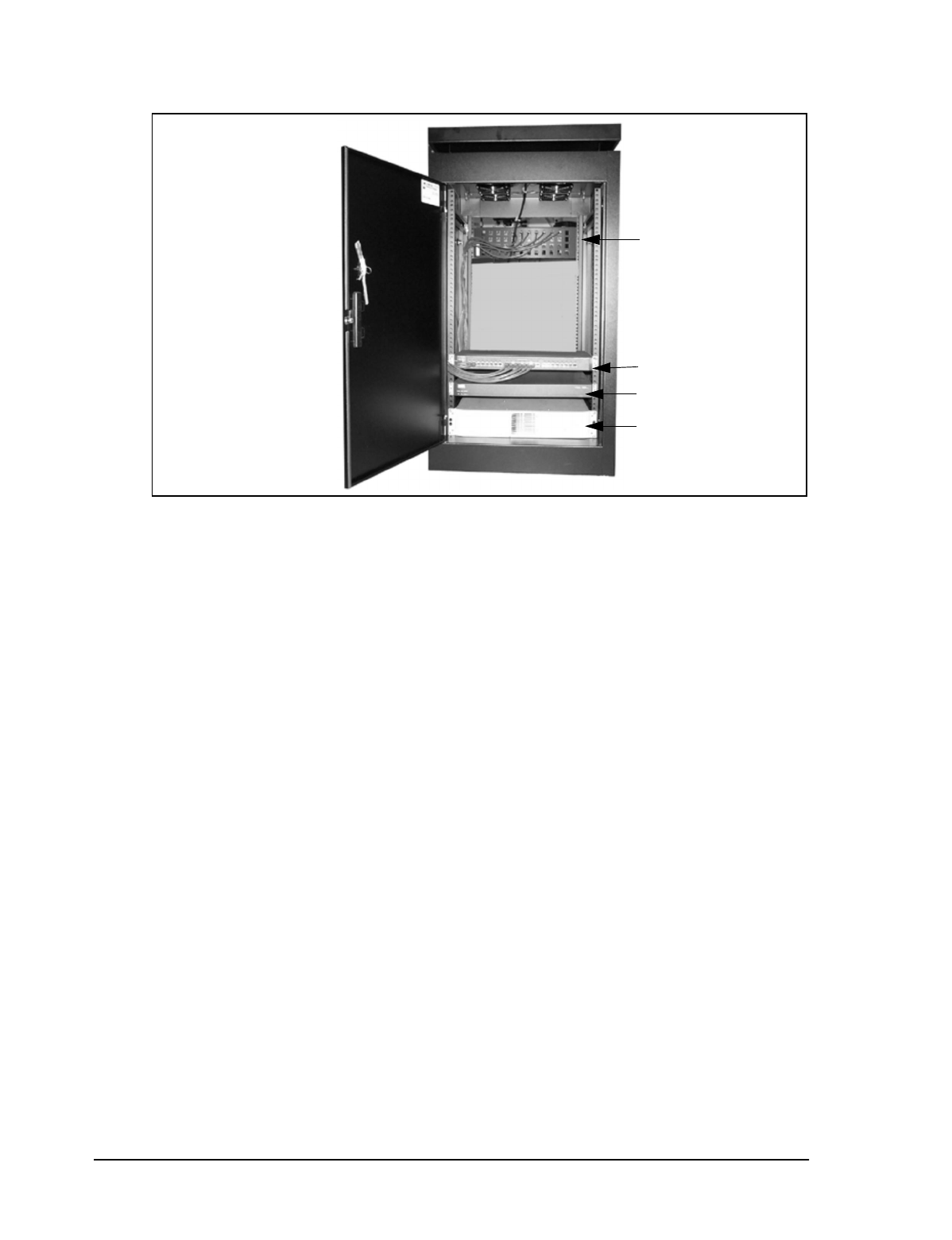
Figure 1 NAP Cabinet
The NAP equipment includes the following components:
•data-entry panel
•Ethernet switch
•router
•uninterruptible power supply (UPS)
•NMS workstation
The data entry panel, switch, router, and UPS are enclosed within a free-standing equipment
cabinet. The NMS workstation is located near the cabinet and is connected to it by an Ethernet
network cable.
Data Entry Panel
Ethernet Switch
Router
NAP UPS
1 Understanding the LMS3200
APCD-LM011-A 3
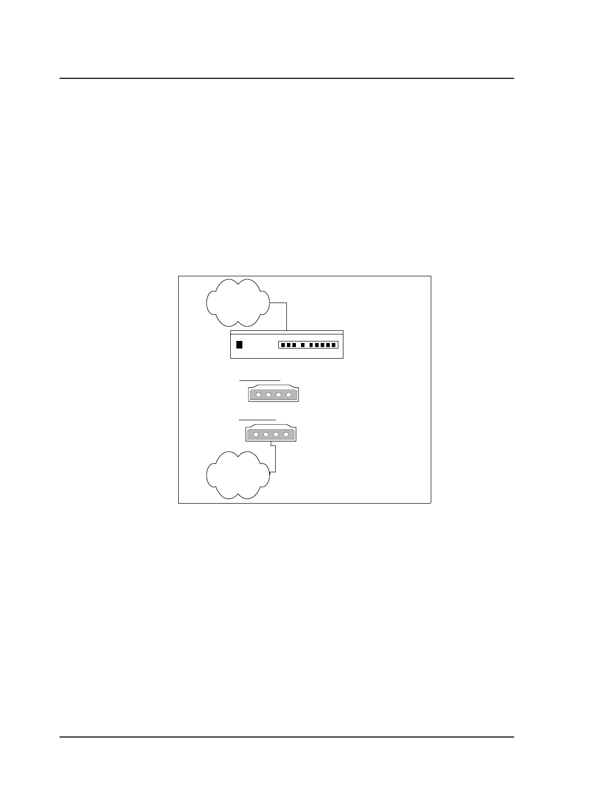
1.2 CAP
The CAP serves a routing function for the LMS3200 data communication by providing a
collection point for the EUM data, and translating this data to a single data stream. It also acts
as a distribution point for data received from the NAP by translating the data from a single data
stream into multiple radio signals. This information then transmits to the appropriate EUMs.
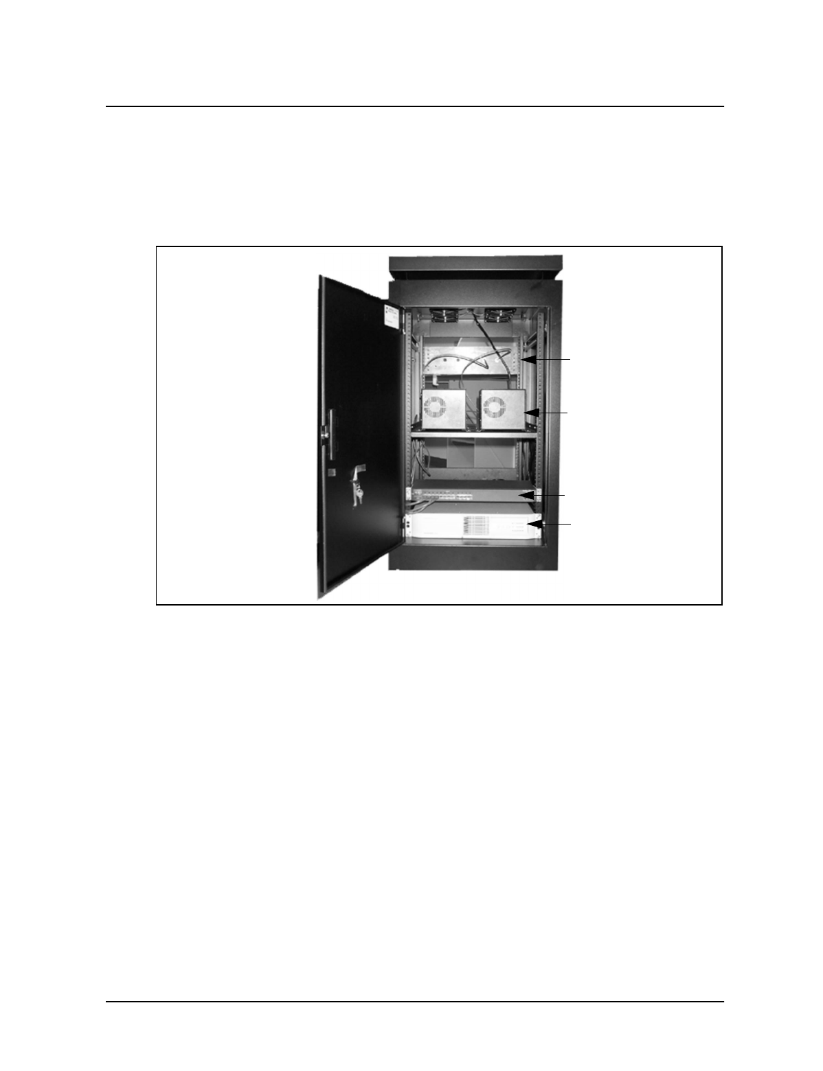
Figure 2 CAP Cabinet
The CAP equipment includes the following components:
•RF entry panel
•CAP channel units (CCUs)
•Ethernet switch
•uninterruptible power supply (UPS)
•RF subsystem, including antenna, antenna tower, lightning arrestors, cabling, and
connectors
•stand-alone backhaul equipment
•additional CCU and RF switch matrix for channel unit redundancy (optional)
Ethernet Switch
CAP Channel Units
CAP UPS
RF Entry Panel
4APCD-LM011-A
1 Understanding the LMS3200
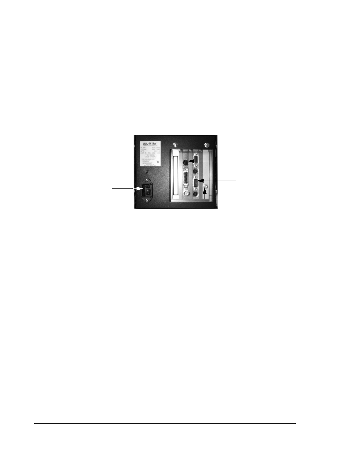
1.3 EUMs
The EUM is a self-contained wireless router that connects directly to a subscriber’s network or
computer. The EUM provides raw data of up to 2.75 Mbps between the EUM and a CCU using
wireless IP routing to create direct high-speed Internet access gateway to and from a local
area network (LAN).
The EUM functions as a radio that transmits or receives data from a local network through an
Ethernet connection, then transmits or receives the coded data through a radio link to the CCU
radio on the CAP.
Figure 3 End User Modem (EUM)
The EUM equipment includes the following components:
•wireless EUM unit with serial, Ethernet, and radio frequency (RF) connections
•outdoor antenna
•supporting equipment, including a power cord and cables
10BaseTx Ethernet
Connector
RS-232 Connector
SMA Antenna
Connector
Power Supply
1 Understanding the LMS3200
APCD-LM011-A 5
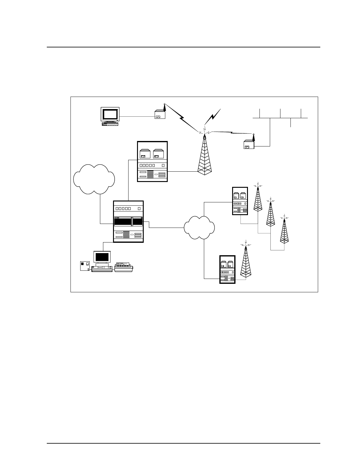
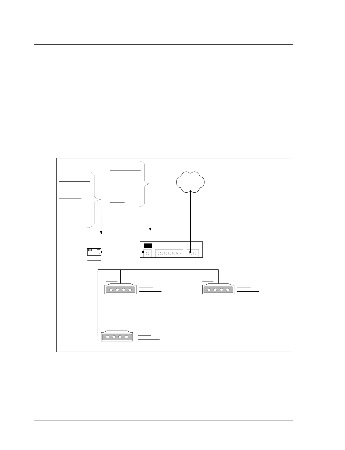
1.4 Network Configuration
LMS3200 System Components on page 5 shows the connections between the components of
the LMS3200 system, the Internet, and the customer’s PC or network.
Figure 4 LMS3200 System Components
ISP/Internet
CAP 2
CAP 3
Up to 30 EUMs per CAP
Channel Unit
Up to 3 CAP Channel
Units (CCUs) per CAP
10/100BaseTx
10/100BaseTx
10/100BaseTx
End User Modem
End User Modem
CAP 1
NAP
Network Management System
6APCD-LM011-A
1 Understanding the LMS3200
1.5 Data Flow
From the simplest perspective, the LMS3200 system consists of the NAP, CAP, and EUM.
The communications between these devices is controlled by routers. The NAP contains a
router, the CAP contains a CCU, which is essentially a router, and the EUM, which also acts
as a router. Each router has two (or more) connections on it.
•The NAP router connects to the WISP (WAN) and the CCU in the CAP (LAN).
•The CCU connects to the NAP (Ethernet) and to multiple EUMs (radio).
•The EUM connects to the CCU (radio) and the subscriber’s PC or network (Ethernet).
System Data Flow on page 6 further illustrates the connections between the Internet, the
LMS3200 equipment, and the subscriber’s computer or LAN. It also identifies typical default IP
addresses for each router.
Figure 5 System Data Flow
Figure 5 shows the default IP addresses for the NAP router, CCU, and EUM. The WAN
interface IP address for the NAP router will change to reflect the subnetwork of the ISP. The
EUM Ethernet IP wll also change to reflect the subscriber’s subnetwork address.
Internet
Subscriber
Network
Interface 0/0
10.2.23.1 /24
Interface 0/1
192.168.10.1 /24
NAP
CCU-1010 Ethernet:
192.168.10.13 /24
Radio:
192.168.110.1
CAP
Ethernet:
192.168.210.2 /24
EUM-101 Radio:
192.168.110.2
EUM

APCD-LM011-A 7
2 Installing the NAP and the CAP
The first step in setting up your LMS3200 network is to link the NAP to the CAP. WaveRider
recommends that you set up the NAP and CAP using the default settings initially. After the
network is operational, you can optionally change the network addresses to suit your needs
using the LMS Network Management System (NMS) software.
The basic procedure for setting up the LMS3200 system, including the CAP to NAP link, is as
follows:
1. Set up the CAP.
2. Set up the backhaul for the CAP to NAP link.
3. Set up the NAP.
4. Set up the NMS Workstation.
5. Configure SNMPc Server.
6. Initialize and configure the NMS software.
7. Verify the CAP and NAP link is operational.
8. Configure CCUs.
9. Configure and deploy EUMs in your network.
This chapter describes the procedures to set up the LMS3200 CAP to NAP components.
2 Installing the NAP and the CAP
8APCD-LM011-A
2.1 Setting up the CAP Using the Default Configuration
The CAP is the first component that you should set up. It consists of the following factory
configured components:
•Cabinet with power bar and fans
•Exide 5119 Uninterruptible Power Supply (UPS)
•Cisco Catalyst 1912 Switch
•CAP Channel Units (CCUs) complete with cables, bulkhead lightning arrestor, power
cords, antennas, and cables
The CAP configuration can include 1 to 3 CCUs, depending on your requirements. Refer to
CAP Default Configuration (CAP #1) on page 8 for the default configuration for the CAP
components. Figure 6 shows CCU configuration.
Figure 6 CAP Default Configuration (CAP #1)
Cisco Catalyst 1912 Switch
192.168.10.10 /24
Cross-Over
Cable
CCU #1
Port Ax
CCU #2 Ethernet: 192.168.10.14 /24
Ethernet: 192.168.10.13 /24
Radio: 192.168.111.1
Radio: 192.168.110.1
Straight Cable Port 3
Port 1
192.168.10.11 /24
Straight
Cable
CAP UPS
Ethernet
BackHaul to NAP
Connect to Port of
NAP Ethernet Switch
CCU #3 Ethernet: 192.168.10.15 /24
Radio: 192.168.112.1
Port 2
Port 4
SNMP Communities:
Read: Public
Write: Private
Trap: Private
Trap Server IP:
192.168.10.7
Write Manager:
192.168.10.7
Password: Cisco
SNMP Communities:
Read: Public
Write: Private
Trap: Private
Trap Server IP:
192.168.10.7
Local ID: 1010
Radio Channel: 3
Local ID: 1011
Radio Channel: 6
Local ID: 1012
Radio Channel: 9

2 Installing the NAP and the CAP
APCD-LM011-A 9
To set up the CAP with the default configuration, use the steps described below:
1. Ensure that your CAP site has been prepared to support the CAP requirements,
including CCU antenna structures, power, grounding, and lightning protection.
WARNING!
This system must be professionally installed. Antennas and
associated transmission cable must be installed by qualified
personnel. WaveRider assumes no liability for failure to adhere
to this recommendation or to recognized general safety
precautions.
2. Reconnect the Exide 5119 UPS battery. Refer to Reconnecting the UPS Battery After
Shipping on page 9.
3. Plug the CAP UPS power cable into a 110 or 220 V AC power source using the
provided cable.
4. Set up your backhaul equipment and connect to the CAP. Refer to Setting up your
Backhaul Equipment on page 11 for more information.
After you have set up the CAP, the next step is to set up the NAP. Refer to Setting up the NAP
Using the Default Configuration on page 12.
2.1.1 Reconnecting the UPS Battery After Shipping
The Exide 5119 UPS is shipped with the battery bank disconnected and the rear breaker on
the rear power distribution bar in the “OFF” position. Reconnect the battery and place the
power switch to the “ON” position. Complete the following instructions before powering up the
unit.
WARNING!
The UPS is capable of generating sufficient voltage to cause
bodily harm. Use extreme caution when working with high
voltage equipment.
10 APCD-LM011-A
2 Installing the NAP and the CAP
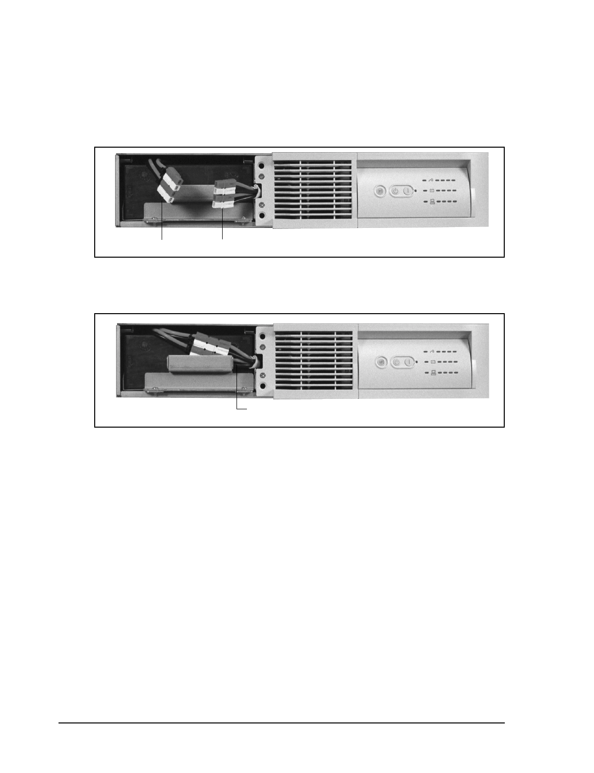
To Reconnect the UPS Battery
1. Open or remove the front and rear doors on the cabinet.
2. Pull the front cover off the UPS to expose the battery connection.
Figure 7 Exide 5119 UPS with Battery Disconnected
3. To reconnect the battery, plug the battery bank plug into the UPS receptacle.
Figure 8 Exide 5119 UPS with Battery Connected
4. Align the front cover in position and snap it back in place.
5. Place the breaker on the rear power distribution bar of the UPS in the “ON” position.
The UPS battery is fully charged before shipping.
6. Plug the UPS into the power source to maintain the charge in the battery.
battery bank plug UPS receptacle
Push the connectors behind the
handle and replace the front cover
2 Installing the NAP and the CAP
APCD-LM011-A 11
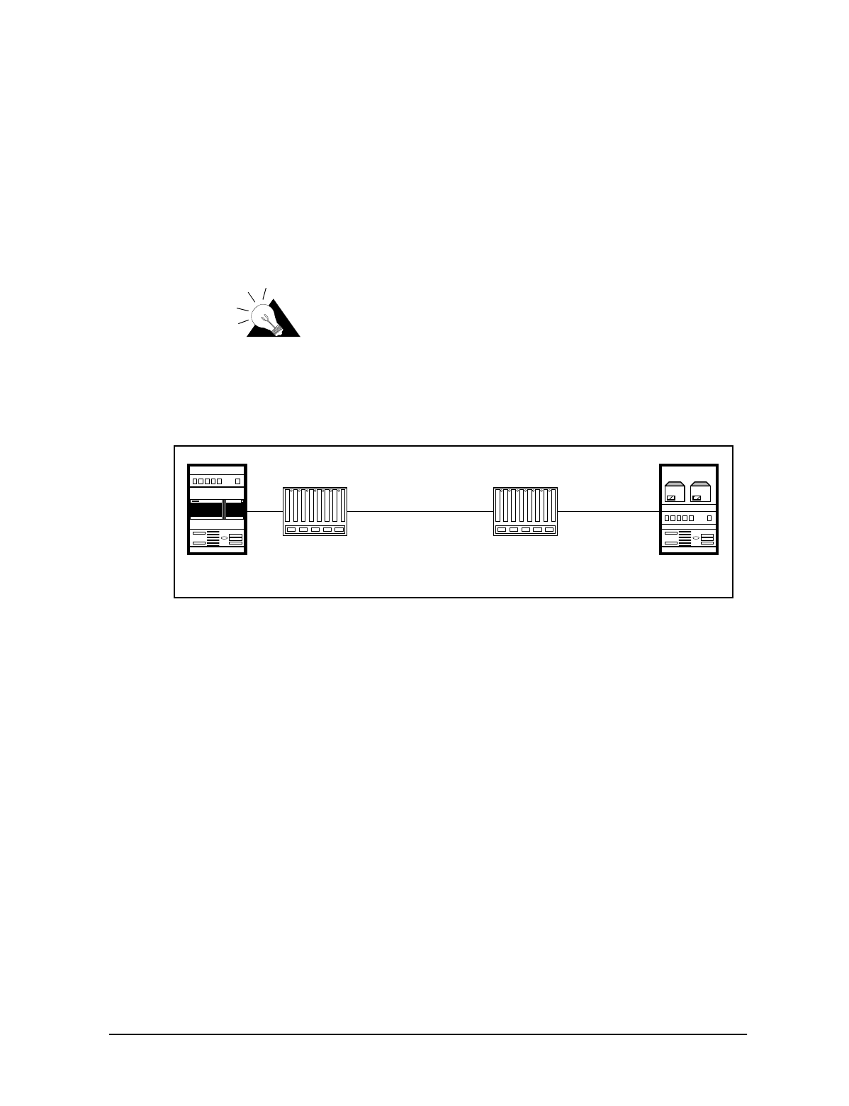
2.1.2 Setting up your Backhaul Equipment
The type of backhaul equipment for your site depends on the following conditions:
•expected traffic load
•available backhaul infrastructure
•distance between the CAP and the NAP
The backhaul can be either a wired connection to the NAP or a connection through an external
unit that provides a transparent connection at the Ethernet Layer 2 transport.
TIP: The WaveRider NCL line of wireless routers
provides a cost-effective solution to establish a wireless
backhaul solution.
CAP to NAP Backhaul on page 11 shows a simple backhaul configuration.
Figure 9 CAP to NAP Backhaul
NOTE: Because the backhaul can be configured in many different ways,
provisioning a backhaul interface for the LMS3200 requires
application engineering. For information on WaveRider backhaul
equipment, contact your WaveRider Sales Representative.
External
Back Haul External
Back Haul
10/100 BaseTx
NxE1/T1, T3, RF, etc.
NAP CAP
12 APCD-LM011-A
2 Installing the NAP and the CAP
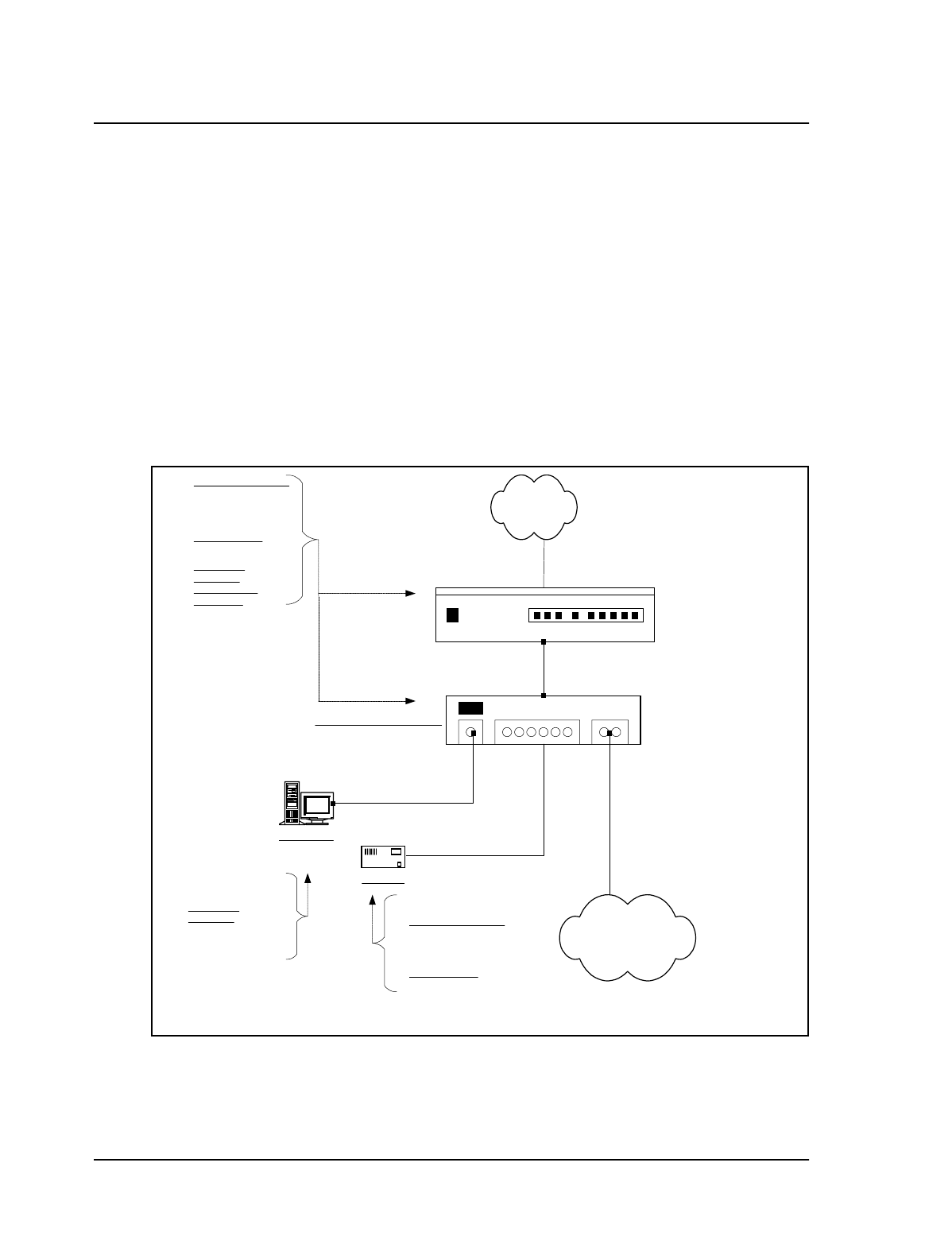
2.2 Setting up the NAP Using the Default Configuration
After you have set up the CAP, the next step is to set up the NAP. The NAP consists of the
following factory configured components:
•Cabinet complete with power bar and fans
•Cisco Catalyst 2924 Switch
•Cisco 2621 Router
•Exide 5119 Uninterruptible Power Supply (UPS)
•NMS Workstation complete with monitor, keyboard, mouse, internal backup tape unit,
printer, and cables
•APC Back-UPS PRO 650 (NMS Workstation UPS)
The NAP components all use the default configuration shown in NAP Configuration on page
12.
Figure 10 NAP Configuration
Cisco Catalyst 2924 Switch
Cisco 2621 Router
Interface 0/0 10.2.23.1 /24
Interface 0/1 192.168.10.1 /24
Port 1
192.168.10.5 /24
NMS Server
Straight
Cable
Straight
Cable
Port 2 Port 24
192.168.10.7 /24
Port 3
192.168.10.6 /24
Straight
Cable
CAP BackHaul
Circuit
To Internet
NAP UPS
Cross-Over
Cable
Connect to Port Ax
on CAP Ethernet
Switch
SNMP Communities:
read: public
write: private
trap: private
Trap Server IP:
192.168.10.7
UserName: cisco
Password: cisco
Enable Secret
Password: cisco
UserName: Admin
Password: (blank) SNMP Communities:
read: public
write: private
trap: private
Trap Server IP:
192.168.10.7

2 Installing the NAP and the CAP
APCD-LM011-A 13
Use the following procedure to set up a NAP:
1. Ensure that your NAP site has been prepared to support the NAP requirements,
including power, grounding, and lightning protection.
2. Reconnect the Exide 5119 UPS battery. Refer to Reconnecting the UPS Battery After
Shipping on page 9.
3. Plug the NAP UPS power cable into a 110 or 220 V AC power source using the
provided cable.
4. Connect the backhaul equipment to a free RJ-45 Ethernet port on the front panel of
the NAP switch. Backhaul equipment must provide transparent Ethernet Layer 2
transport between the NAP and CAP. Refer to Setting up your Backhaul Equipment
on page 11 for more information.
5. Power up the NAP.

— This page is intentionally left blank —