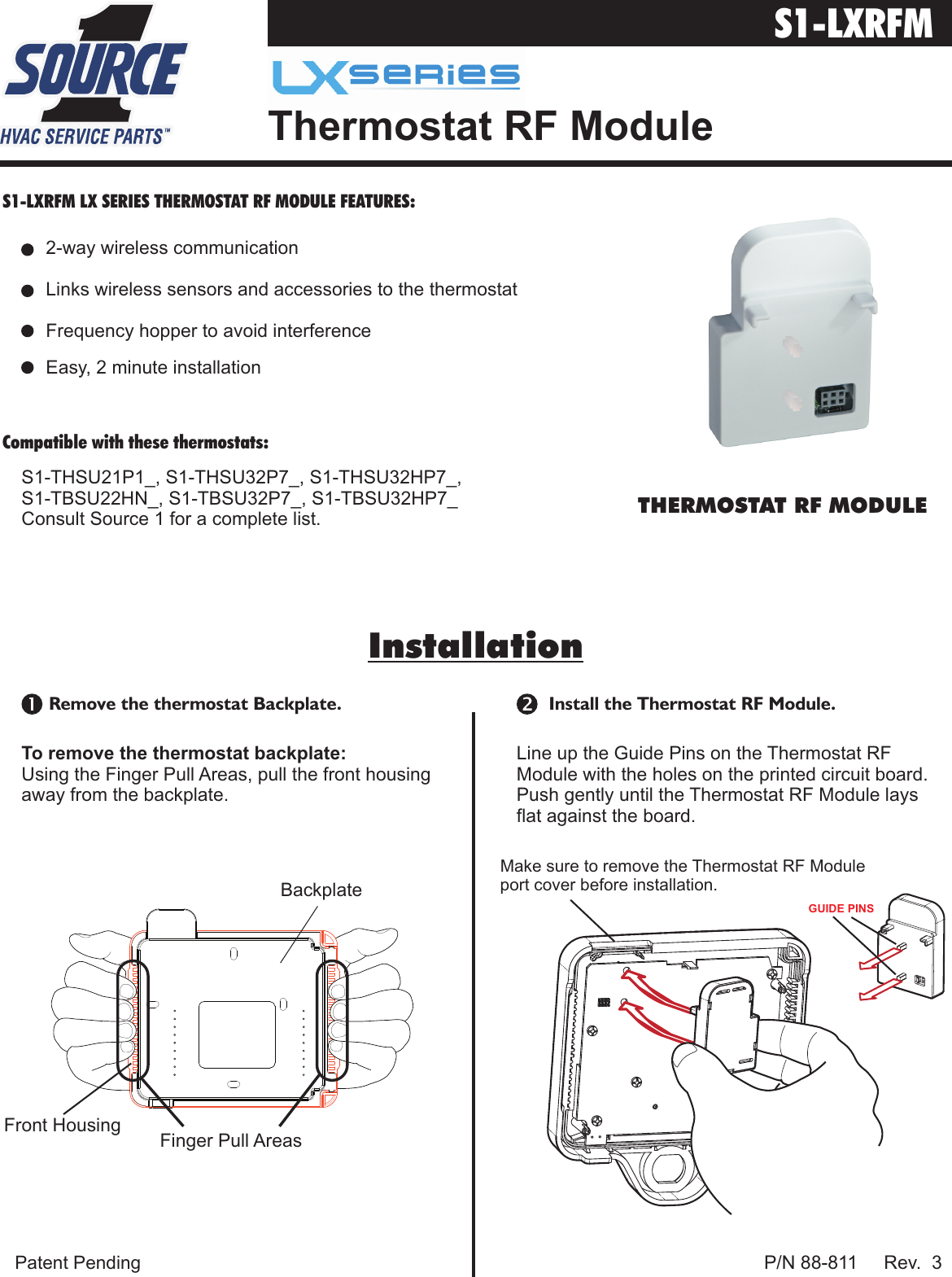
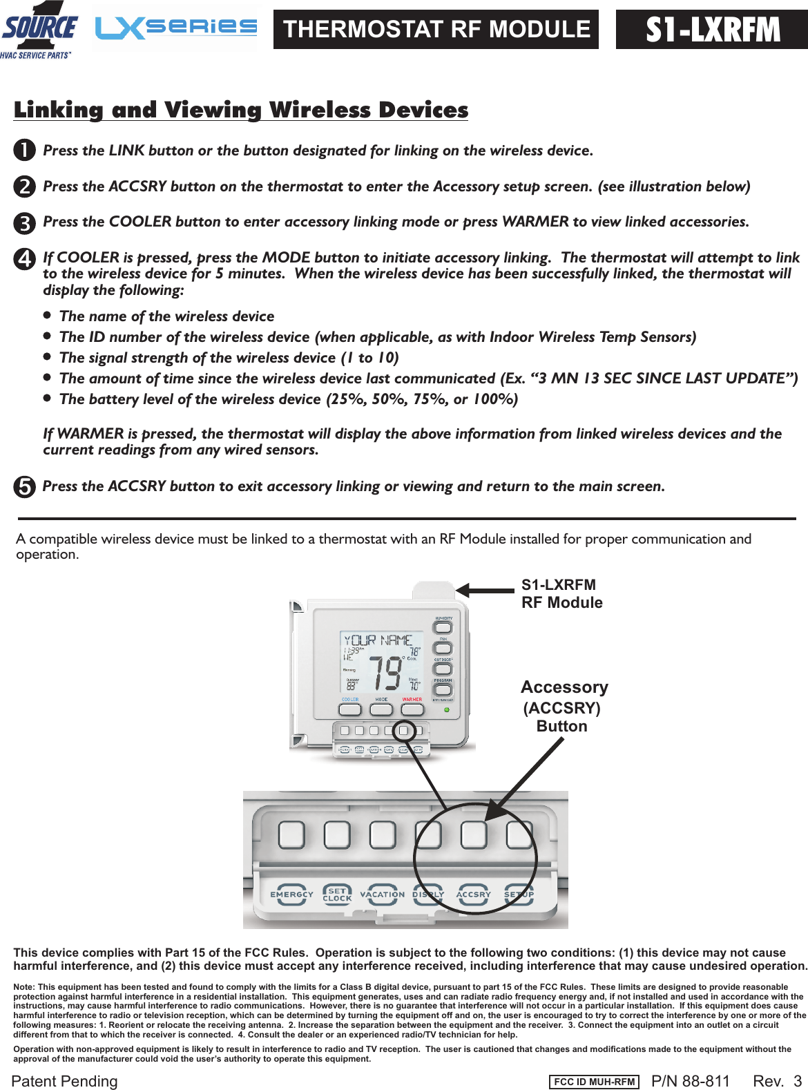
Venstar RFM Thermostat RF Module User Manual

Venstar Inc Thermostat RF Module Users Manual

Users Manual

 Patent Pending           P/N 88-811     Rev.  3S1-LXRFM LX SERIES THERMOSTAT RF MODULE FEATURES:Compatible with these thermostats:   InstallationInstallationInstall the Thermostat RF Module.                   S1-LXRFM           Thermostat RF ModuleFront Housing Backplate Finger Pull AreasTo remove the thermostat backplate: Using the Finger Pull Areas, pull the front housing away from the backplate. Remove the thermostat Backplate.Line up the Guide Pins on the Thermostat RF Module with the holes on the printed circuit board.  Push gently until the Thermostat RF Module lays flat against the board.THERMOSTAT RF MODULE 2-way wireless communication  Links wireless sensors and accessories to the thermostat  Frequency hopper to avoid interference  Easy, 2 minute installation  S1-THSU21P1_, S1-THSU32P7_, S1-THSU32HP7_,S1-TBSU22HN_, S1-TBSU32P7_, S1-TBSU32HP7_Consult Source 1 for a complete list. GUIDE PINSMake sure to remove the Thermostat RF Module port cover before installation.
Patent Pending          Linking and Viewing Wireless Devices A compatible wireless device must be linked to a thermostat with an RF Module installed for proper communication and operation.S1-LXRFMTHERMOSTAT RF MODULERF Module(ACCSRY)ButtonAccessoryS1-LXRFMPress the LINK button or the button designated for linking on the wireless device.Press the ACCSRY button on the thermostat to enter the Accessory setup screen. (see illustration below)                                                                                                                                                                                                                                                  Press the COOLER button to enter accessory linking mode or press WARMER to view linked accessories.54                                                                             If COOLER is pressed, press the MODE button to initiate accessory linking.  The thermostat will attempt to link       to the wireless device for 5 minutes.  When the wireless device has been successfully linked, the thermostat will        display the following:The name of the wireless device                                                                              The ID number of the wireless device (when applicable, as with Indoor Wireless Temp Sensors)                                                                              The signal strength of the wireless device (1 to 10)                                                                              The amount of time since the wireless device last communicated (Ex. “3 MN 13 SEC SINCE LAST UPDATE”)                                                                              The battery level of the wireless device (25%, 50%, 75%, or 100%)                                                                                                                                                           If WARMER is pressed, the thermostat will display the above information from linked wireless devices and the        current readings from any wired sensors.                                                                               Press the ACCSRY button to exit accessory linking or viewing and return to the main screen.P/N 88-811     Rev.  3 FCC ID MUH-RFMNote: This equipment has been tested and found to comply with the limits for a Class B digital device, pursuant to part 15 of the FCC Rules.  These limits are designed to provide reasonableprotection against harmful interference in a residential installation.  This equipment generates, uses and can radiate radio frequency energy and, if not installed and used in accordance with theinstructions, may cause harmful interference to radio communications.  However, there is no guarantee that interference will not occur in a particular installation.  If this equipment does cause harmful interference to radio or television reception, which can be determined by turning the equipment off and on, the user is encouraged to try to correct the interference by one or more of thefollowing measures: 1. Reorient or relocate the receiving antenna.  2. Increase the separation between the equipment and the receiver.  3. Connect the equipment into an outlet on a circuit different from that to which the receiver is connected.  4. Consult the dealer or an experienced radio/TV technician for help.This device complies with Part 15 of the FCC Rules.  Operation is subject to the following two conditions: (1) this device may not cause harmful interference, and (2) this device must accept any interference received, including interference that may cause undesired operation.Operation with non-approved equipment is likely to result in interference to radio and TV reception.  The user is cautioned that changes and modifications made to the equipment without the approval of the manufacturer could void the user’s authority to operate this equipment.

Navigation menu