Venstar SKYPORT2 ColorTouch User Manual Model 1
Venstar Inc ColorTouch Users Manual Model 1
Venstar >
Contents
- 1. Users Manual Model 1
- 2. Users Manual Model 2
- 3. Users Manual Model 3
- 4. Supplemental Users Info Revised
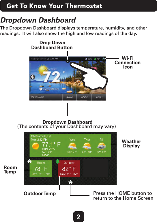
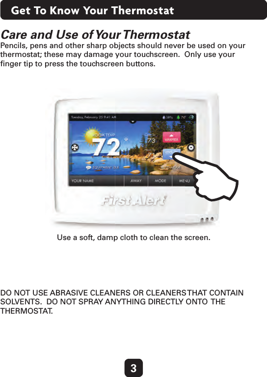
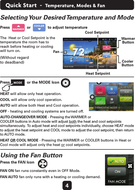
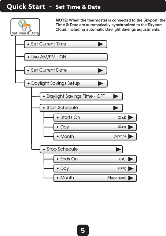
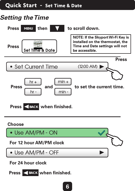
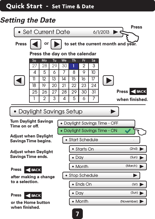
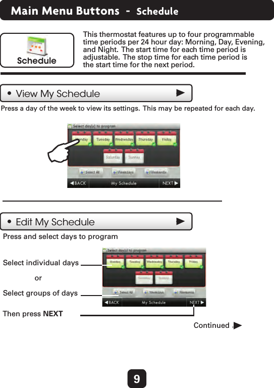
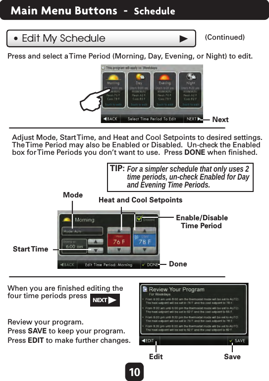
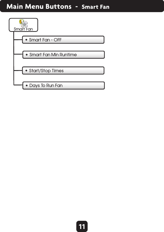
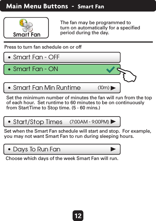
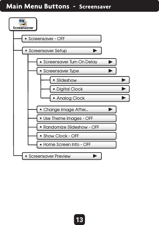
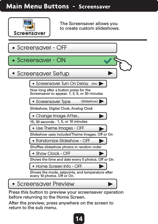
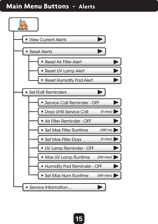
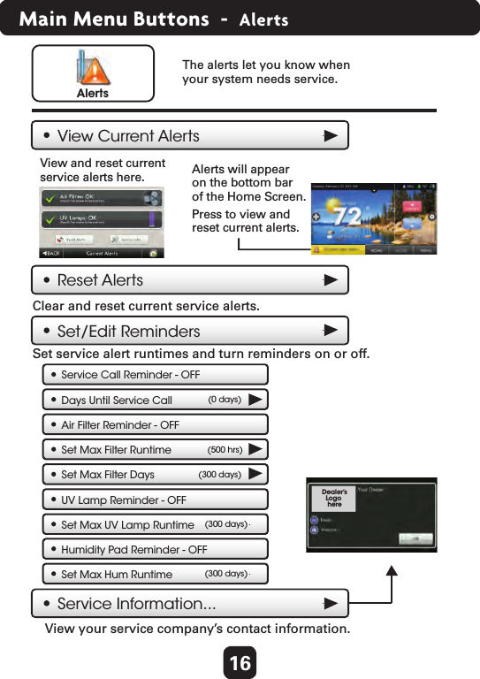
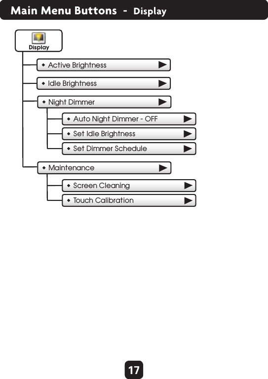
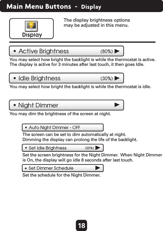
Users Manual Model 1