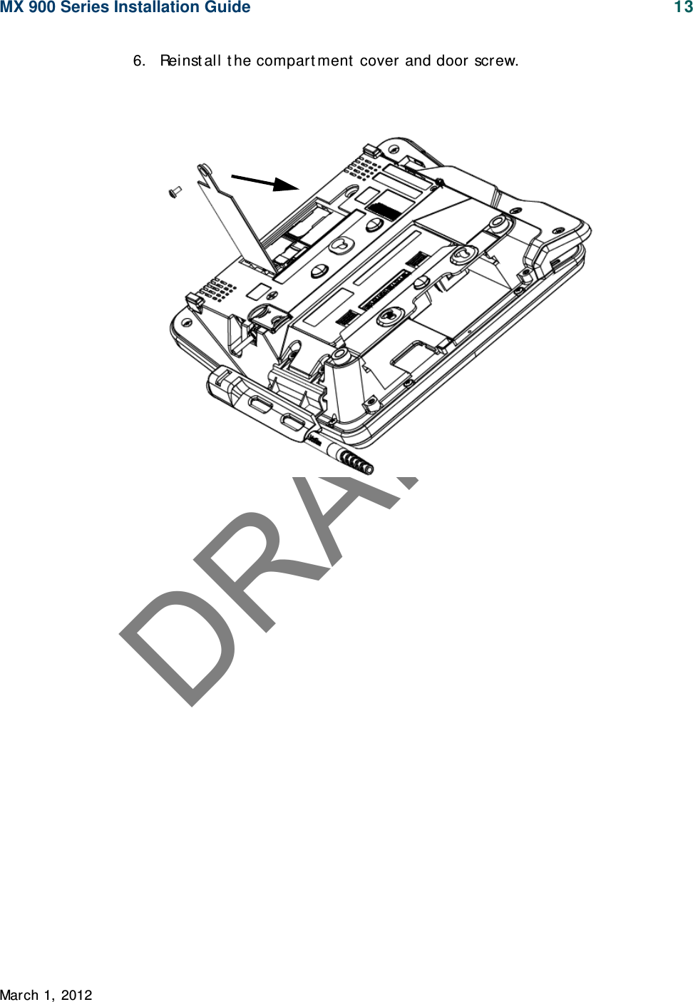
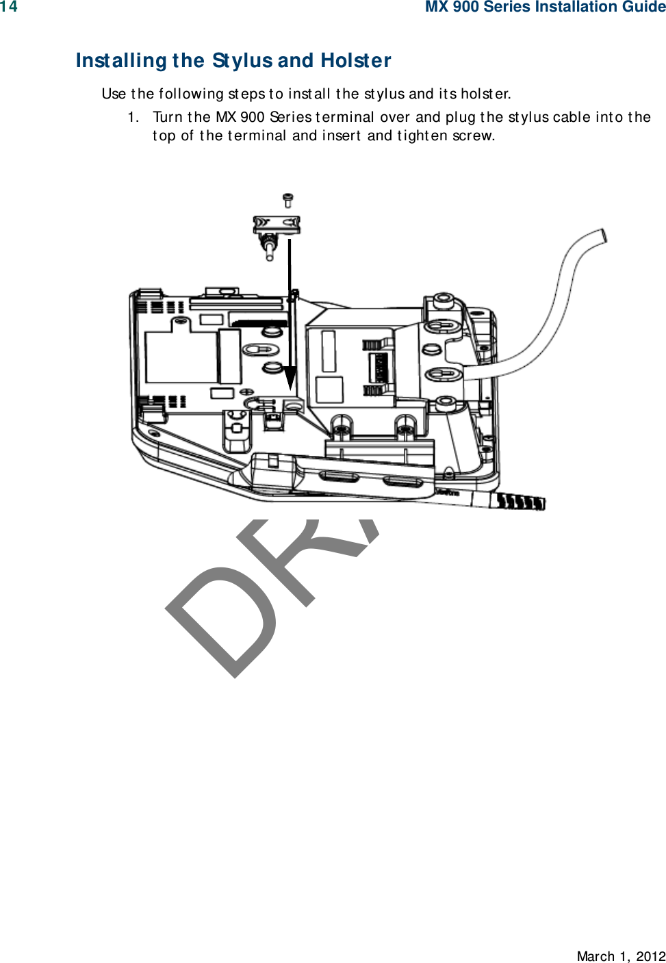
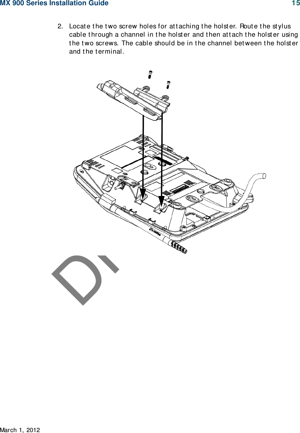
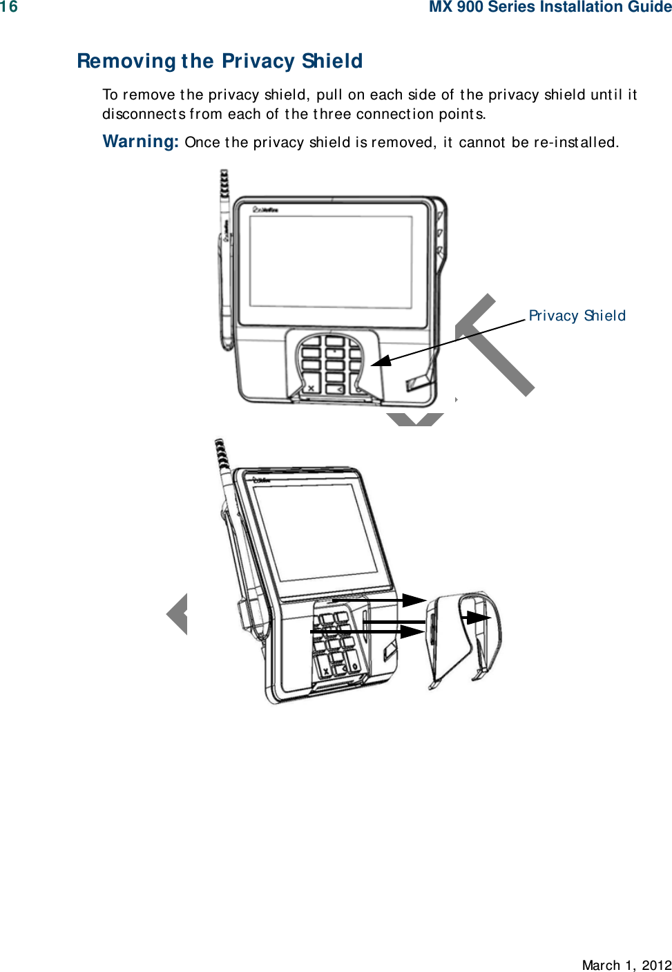
Verifone MX925CTLS Point of Sale Terminal User Manual MX900Install

VeriFone Inc Point of Sale Terminal MX900Install

User Manual

DRAFTMX 900 SeriesInst allat ion Guide
DRAFT
DRAFTMX 900 Series Installation GuidePart Number SPC132-022-01-A, Revision AMarch 1, 2012Ve r iFone ®,  Inc.2099 Gat eway PlaceSuit e 600San Jose,  CA 95110Telephone:  408-232-7800ht t p: / / www.verifone. comPrint ed in t he Unit ed St at es of  America.© 2012 by VeriFone,  Inc.No part  of t his publicat ion covered by t he copyright s herein may be reproduced or copied in any form or by any means — graphic,  elect ronic, or mechanical, including phot ocopying, t aping, or inf ormat ion st orage and ret rieval syst ems — wit hout  writ t en permission of  t he publisher.The cont ent s of  t his document  and all f eat ures and specif icat ions are subj ect  t o change wit hout  not ice.  The inf ormat ion cont ained herein does not  represent  a commit ment  on t he part  of   VeriFone,  Inc.Publicat ions are not  st ocked at  t he address given above.  Request s f or VeriFone publicat ions should be made t o your VeriFone represent at ive.VeriFone,  t he VeriFone logo, and Ruby SuperSyst em are regist ered t rademarks of  VeriFone,  Inc.  Sapphire, Topaz,  HPV-20, Ruby Manager,  Everest , EASY ID, Elect ronic Journal On-sit e,  and Ruby Card are t rademarks of  VeriFone,  Inc.  in t he U. S. and/ or ot her count ries. All ot her t rademarks or brand names are t he propert ies of  t heir respect ive holders.
DRAFT
DRAFTMarch 1, 2012Contents1.  Introduction.  . . .  . .  . . .  . . . .  . .  . . .  . . .  . . .  . .   1Int ended Audience  . . . . . . . . . . . . . . . . . . . . . . . . . .  1Document  Organizat ion . . .  . .  .  . . . . . . . . . . . . . . . . .  1Modificat ions t o t his document  . . . . . . . . . . . . . . . .  . . . .  1Acronyms,  Abbreviat ions, and Def init ions  . . . . .  . . . . . . . .  22.  Hardware Installation  . .  . .  . . . .  . .  . . .  . . . .  . .    3Inst alling t he Device  .  .  . . . . . . . . . . . . . . . . . . . . . . . . .  3To unpack t he shipping cart on . . . .  . . . .  . . . .  .  . . .  .  . . . .  3Selecting a Locat ion  .  .  . . . . . . . . . . . . . . . . . . . . . . . . .  4St and Mount .  . . . . . . . . . . . . . .  .  . . . . . . . . . . . . . . . . .  5Wall Mount . . . . . . . . . . . . . . . . . . . . . . . . . .  . . . . . . . .  6PIN Prot ect ion Measures .  . .  .  . . . . . . . . . . . . . . . . . . . . .  7Inst alling Opt ional Component s .  . . . . . . . . . . . . . . . . . . .  8Inst alling Count ert op Wedge .  . . . . . . . . . . . . . . . . . . .  8Removing or Inst alling t he I/ O Module  .  . .  .  . .  . .  .  . . . .  9Inst alling MSAM or SD Cards  .  . .  . . . . . . . . . . . . . . . .   10Inst alling t he St ylus and Holst er  .  . . . . . . . . . . . . . . .   14Removing t he Privacy Shield . . . . . . . . . . . .  . . . . . . .   16Connect ing t he Device . . . . . . . . . . . . . . . . .  .  . . . . . . .   17I/ O Module  .  . . . . . . . . . . . . . . . .  .  . . . . . .  . .  .  . . .   17Mult iport  Cable  . . . . . . . . . .  .  . . .  .  . . . . . . . . . . . .   18Connect ing ECR in Tailgat e Mode . . .  .  . . .  .  . .  . . . . . .   20Connect ing t o a Host  PC. . . . . . . . . . . . . . . . . . . . . .   21Connect ing t o t he Et hernet  LAN  . . . . . . . . . . . . . . . .   21Connect ing t o USB Host  or Hub  .  . . . . . . . .  .  . . . . . . .   21Powering up .  . . . . . . . . . . . . . . .  . . . . . . . . . . . . . . . .   22Using t he I/ O Module . . . . .  . .  .  . . . . . . . . . . . . . . . .   22Using t he Mult iport  Cable . . . . . . . . . . . . . . . . . . . . .   23Calibrat e Touch Screen  . . .  .  . . . . . . . . . . . . . . . . . . . .   243.  Maintenance  . . . . .  . .  . . .  . . .  . . .  . . .  . . .  . .  .  25
DRAFTii MX 900 Series Installation GuideMarch 1,  2012Cleaning t he Terminal .  . . . . . . . . . . . . . . . .  .  . . . . . .  . .  25Cleaning t he Display Screen . . . . . . . . . . . . . . . . . . . . . .  25Magnet ic St ripe Cleaner. . . . . . . . . . . . .  . . . . . . . . . . . .  25Smart  Card Reader . . . . . . . . . . . . . .  .  . . . . . .  . .  .  . .  . .  254.  Terminal Specifications.  . . .  . .  . . .  . . .  . . .  . . .  27Terminal Specif icat ions .  . . . . . . . . . . . . . . . . . . .  .  . .  . .  27
DRAFTMarch 1, 20121 INTRODUCTIONThis inst allat ion guide is your primary source of  informat ion for set t ing up and inst alling t he MX 900 Series t erminals,  t he MX 915™ and MX 925™. Intended AudienceThis guide is usef ul for anyone inst alling and conf iguring t he MX 900 Series t erminals. A basic descript ion of  t erminal f eat ures is also provided.Document OrganizationThe following chapt ers are included:Chapt er 1, Int roduct ion,  explains t he Int ended Audience,  Document  Organizat ion,  and common acronyms, abbreviat ions, and definit ions used.Chapt er 2, Inst allat ion, explains how t o inst all t he MX 900 Series t erminals.Chapt er 3, Maint enance,  explains how t o maint ain your MX 900 Series t erminals.Chapt er 4, Specif icat ions,  provides inf ormat ion on power, environment , and dimensions of  t he hardware.Modifications to this documentThis document  may be changed or ext ended t o include new product  requirement s.
DRAFT2MX 900 Series Installation GuideMarch 1,  2012Acronyms, Abbreviations,  and DefinitionsThe following t able describes t he common acronyms,  abbreviat ions,  and def init ions used:Convention MeaningBFI Buf f er Flush Int ervalbps bit s per secondCRC Cyclic Redundancy CheckFA File Aut hent icat ionFirmware Sof t ware in FLASH/ ROMFTP File Transf er Prot ocolGISKE Global Int eroperable Secure Key ExchangeiPKG The It sy Package Management  Syst emIPP Int ernal PIN PadISR Int errupt  Service Rout ineJFFS2 Journaling Flash File Syst emKLK VSS Key Loading KeyKSN Key Serial NumberKVC Key Verificat ion CodeLED Light  Emit t ing DiodeMS Mast er SessionMSR Magnet ic St ripe ReaderNFS Net work File Syst emOSS Open Sound Syst emPED PIN Ent ry DevicePEK PIN Encrypt ion KeyRFCR RF Card ReaderRRT Receive Record ThresholdRTC Real-t ime ClockSAM Securit y Access ModuleVRK  VeriShield Remot e KeyVSS VeriShield Securit y Script s
DRAFTMarch 1, 20122 HARDWARE INSTALLATIONThis chapt er describes t he MX 900 Series inst allat ion procedures and includes connect ion examples.Installing the DeviceThis sect ion present s inst allat ion guidelines for t he MX 900 Series t erminal.Unpacking Open t he shipping cart on and carefully inspect  t he cont ent s for possible t ampering or shipping damage.War ning:Do not  use a damaged t erminal.To unpack the shipping carton1. Wit h t he shipping cart on right  side up, open t he t op and remove all it ems from t he cart on:– Terminal unit– Power pack (Separat e Packaging)–Berg retainer2. Remove t he prot ect ive plast ic wrap f rom t he display and ot her component s.Berg Ret ainerPow er  Pack(Separat e Cart on)
DRAFT4MX 900 Series Installation GuideMarch 1,  20123. Place t he component s on a t able or count ert op.4. Save t he shipping cart ons and packing mat erial for repacking or moving in t he fut ure.Selecting a LocationWar ning:The MX 900 Series t erminal is designed for indoor use only.Use t he following guidelines t o select  a locat ion for t he MX 900 Series t erminal.1. Select  a locat ion for t he t erminal t hat  of f ers adequat e vent ilat ion and prot ect ion and is convenient  for t he user and merchant .2. Place t he MX 900 Series t erminal on a f lat  surf ace,  such as a t able or count ert op, or mount  it  on a mount ing st and supplied by VeriFone. Avoid areas wit h:– Excessive heat  or dust– Oil or moist ure– Devices t hat  cause excessive volt age fluct uat ions or elect rical noise, such as air condit ioners,  f ans, elect ric mot ors,  neon signs,  or high-frequency securit y devices must  be no closer t han 24 inches– Direct  sunlight  or obj ect s t hat  radiat e heatNote: Interference Sources:Special care is required when mount ing t he MX 900 Series t erminal in sit es t hat  ut ilize ant i-t hef t  devices posit ioned at  doorways or surface mount ed deact ivat or pads.  Devices of  t his t ype, such as Sensormat ic brand devices,  generat e st rong elect romagnet ic f ields which may int erfere wit h MX 900 Series t erminals. Always select  mount ing locat ions at  least  6 feet  f rom doorway unit s and at  least  18 inches from surf ace mount ed deact ivat or pads.  Note: Mounting Considerations:VeriFone recommends t he use of  an approved st and f or all mount ing sit uat ions. Posit ion t he t erminal convenient ly in relat ion t o power,  ECR and LAN connect ions.  Ensure t he MX 900 Series t erminal is locat ed in a manner t hat  allows cust omers t o swipe t heir magnet ic cards or insert  t heir Smart  Cards in a smoot h and comfort able mot ion wit hout  encount ering obst ruct ions. If  t he unit  will be swiveled during normal operat ion,  VeriFone requires t he use of  an approved swivel st and.  The st and must  limit  t he swivel t o 180 degrees t o prevent  t wist ing and damage t o t he MX 900 Series cable.  Aft er mount ing, verif y all cables move f reely and do not  t wist  when t he unit  is rot at ed t hroughout  it s range of  mot ion.
DRAFTMX 900 Series Installation Guide 5 March 1, 2012War ning:Do not  use t he MX 900 Series t erminal near wat er,  including a bat ht ub, wash bowl,  kit chen sink,  or laundry t ub.  Do not  use in a wet  basement  or near a swimming pool.3. Before connect ing t he t erminal t o t he power pack, complet e t he inst allat ion by connect ing all t he cables (see Connect ing t he Device and Power Up wit h t he Mult iport  Cable).Stand MountIn most  ret ail spaces,  t he t erminal is posit ioned on a st and mount .  To inst all t he t erminal on t he st and mount :1. Inst all t he st and mount  on t he count ert op in t he desired lane over an appropriat e hole t hrough which t he wiring connect ions can be t hreaded.2. Thread all wiring connect ions t hrough t he cent er of  t he st and mount .3. Make all wiring connect ions.4. Align and seat  t he t hree pins on t he t op plat e of  t he st and mount  plat f orm wit h t he t hree key-hole slot s on t he bot t om of  t he t erminal.5. Slide t he t erminal down unt il t he unit  seat s securely.6. Posit ion t he st and so t hat  it  is prot ect ed f rom being bumped by shopping cart s or ot her it ems. Being bumped and pot ent ially t rigger t he syst em int o “ t hinking”  a breach at t empt  has occurred, causing t he encrypt ion keys t o be cleared.
DRAFT6MX 900 Series Installation GuideMarch 1,  2012Wall MountThe MX 900 Series t erminal can be mount ed on a wall. To wall mount  t he MX 900 Series t erminal:1. Creat e a t emplat e of  t he t hree key hole slot s on t he bot t om of  t he MX 900 Series t erminal.2. Locat e a wall st ud t o base cent er placement  of  t he MX 900 Series t erminal unit .3. Mark t he hole placement  on t he desired wall locat ion.4. Prepare holes f or screw placement .  For mount ing int o drywall use 1/ 8" Hollow Wall Anchors.  Ot her st ud mount ings use #6 t rim screws. Af t er inst allat ion apply 30 pounds force downward t o ensure proper mount ing.a. Creat e a small hole in which t o screw in self -t apping wood screws,  orb. Insert  molly screws int o prepared holes in sheet  rock wall.5. Insert  screws int o prepared holes,  leaving approximat ely 6.35mm (1/ 4” ) of  t he screw above t he level of t he wall.Note: Adj ust  t he screw dept h t ill t he unit  is firmly mount ed.6. Align and seat  screws in t he key hole slot s.7. Slide t he MX 900 Series t erminal down unt il t he unit  seat s securely.Key Hole Slot sMount ing Holes
DRAFTMX 900 Series Installation Guide 7 March 1, 2012PIN Protection MeasuresThe following t echniques can be employed t o provide for ef f ect ive screening of t he PIN-ent ry keypad during t he PIN-ent ry process.  These met hods would t ypically be used in combinat ion,  t hough in some cases a met hod might  be used singly.■Posit ioning of  t erminal on t he check-st and in such a way as t o make visual observat ion of t he PIN-ent ry process inf easible. Examples include:– Visual shields designed int o t he check-st and. The shields may be solely for shielding purposes,  or may be part  of  t he general check-st and design.– Posit ion t he PIN Ent ry Device (PED) so t hat  it  is angled in such a way t hat  PIN spying is diff icult .■Inst alling PED on an adj ust able st and t hat  allows consumers t o swivel t he t erminal sideways and/ or t ilt  it  forwards/ backwards t o a posit ion t hat  makes visual observat ion of  t he PIN-ent ry process dif f icult .■Posit ioning of  in-st ore securit y cameras so t hat  t he PIN-ent ry keypad is not  visible.The following t able describes t he t wo pref erred mount ing met hods and t he recommended measure t o prot ect  f rom PIN capt ure in four observat ion corridors:VeriFone also recommends inst ruct ion of  t he cardholder regarding saf e PIN-ent ry. This can be done wit h a combinat ion of :■Signage on t he PED■Prompt s on t he display, possibly wit h a “ click-t hrough”  screen■Lit erat ure at  t he point  of sale■A logo for safe PIN-ent ry processNote: For a det ailed discussion of  PINpad Securit y Best  Pract ices, see t he MX 900 Ref erence Manual.Mounting Methods and Protection MeasuresMethod Cashier Customer QueueCount ert op wit hout  st andUse signage behind t he PEDInst all so t hat  cust omer is bet ween PED and next  in queueCount ert op wit h St andNo Act ion NeededInst all so t hat  cust omer is bet ween PED and next  in queue
DRAFT8MX 900 Series Installation GuideMarch 1,  2012Installing Optional ComponentsThis sect ion discusses t he inst allat ion procedures for t he opt ional component s available for t he MX 900 Series t erminal.  Your t erminal may already have some of  t hese opt ions,  as modules can be inst alled at  t he fact ory or in t he field.Installing Countertop Wedge The count ert op wedge raises t he rear sect ion of  t he MX 900 Series t erminal by an angle of  10 degrees t o facilit at e use of  t he screen.  See t he St and Mount  sect ion for aligning t he pins.To install the countertop wedge1. Align t he pins in t he count ert op wedge wit h t he t wo key holes on t he bot t om of t he MX 900 Series t erminal.2. Slide t he count ert op wedge f irmly int o posit ion.
DRAFTMX 900 Series Installation Guide 9 March 1, 2012Removing or Installing the I/ O ModuleUse t he following st eps t o remove and inst all  I/ O modules.Push down t he t wo t abs so t hat  t he I/ O module can slide out .Ta b sTa b s
DRAFT10 MX 900 Series Installation GuideMarch 1,  2012Slide t he module in unt il it  locks int o place.Installing MSAM or SD Cards Follow t he st eps below t o inst all smart  cards (MSAM or SD cards).Oft en merchant s are issued MSAM or SD cards t o run small applicat ions, such as loyalt y programs.  MSAM and SD cards are used only wit h MX 900 Series t erminal smart  card conf igurat ions.1. Unplug t he power pack from t he mult iport  cable or unplug f rom t he I/ O module if no mult iport  cable is present .2. Place t he t erminal upside down on a sof t , clean surf ace t o prot ect  t he glass cover from scrat ches.I/ O ModulesTerminal Description Terminal P/ N I/ O Module P/ NMX 915AUD, BERG ONLY, NO TAILGATEP132-601-00-R MX900-01PWR,  AUD,  BERG W/  TAILGATE, ETH, USB OTG,  COM 2P132-602-00-R MX900-02PWR, AUD,  POE, USB OTG, USB HOST,  COM 1, COM 2P132-603-00-R MX900-03PWR, AUD, ETH, USB OTG,  COM 1, WIFI/ BTP132-604-00-R MX900-04MX 925AUD, BERG ONLY, NO TAILGATEP132-601-00-R MX900-01PWR,  AUD,  BERG W/  TAILGATE, ETH, USB OTG,  COM 2P132-602-00-R MX900-02PWR, AUD,  POE, USB OTG, USB HOST,  COM 1, COM 2P132-603-00-R MX900-03PWR, AUD, ETH, USB OTG,  COM 1, WIFI/ BTP132-604-00-R MX900-04
DRAFTMX 900 Series Installation Guide 11 March 1, 20123. Remove t he card compart ment  door screw and rot at e t he door up and back t o access t he SD and MSAM cardholders.4. Remove any previously inst alled MSAM or SD card by sliding t he card from t he cardholder.
DRAFT12 MX 900 Series Installation GuideMarch 1,  2012Note: Bef ore insert ing t he SD or MSAM card,  posit ion it  wit h t he card’s gold cont act s f acing t he smart  card reader end of t he t erminal. The cardholder connect or base has a set  of  cont act s and a not ch on one corner t o ensure t he card is posit ioned correct ly. The card has a not ch on one corner t o ensure t hat  it  f it s int o t he connect or base in only one way. The card compart ment  door will not  close properly if t he cards are inst alled incorrect ly.5. Inst all an MSAM or SD card by aligning t he card and caref ully sliding it  wit hin t he guides on t he cover unt il it  is f ully insert ed.
DRAFTMX 900 Series Installation Guide 13 March 1, 20126. Reinst all t he compart ment  cover and door screw.
DRAFT14 MX 900 Series Installation GuideMarch 1,  2012Installing the Stylus and HolsterUse t he following st eps t o inst all t he st ylus and it s holst er.1. Turn t he MX 900 Series t erminal over and plug t he st ylus cable int o t he t op of  t he t erminal and insert  and t ight en screw.
DRAFTMX 900 Series Installation Guide 15 March 1, 20122. Locat e t he t wo screw holes for at t aching t he holst er. Rout e t he st ylus cable t hrough a channel in t he holst er and t hen at t ach t he holst er using t he t wo screws.  The cable should be in t he channel bet ween t he holst er and t he t erminal.
DRAFT16 MX 900 Series Installation GuideMarch 1,  2012Removing the Privacy ShieldTo remove t he privacy shield,  pull on each side of t he privacy shield unt il  it  disconnect s f rom each of  t he t hree connect ion point s.War ning: Once t he privacy shield is removed,  it  cannot  be re-inst alled.Privacy Shield
DRAFTMX 900 Series Installation Guide 17 March 1, 2012Connecting the DeviceThis sect ion provides brief  descript ions of  possible MX 900 Series t erminal device connect ions and t he power pack connect ion. For complet e inf ormat ion about  inst alling and using an opt ional device,  see t he user document at ion supplied wit h t hat  device.Ensure t hat  t he mult iport  cable or I/ O module is not  connect ed t o a power pack bef ore at t aching t o t he MX 900 Series t erminal.I/ O ModuleThe MX 900 Series t erminals use one of  f our I/ O Modules wit hout  t he mult iport  cable t o make t he f ollowing connect ions:  Note: Use t he Et hernet  port  on t he I/ O module only if  t he mult iport  cable is not  at t ached. Ot herwise,  use t he Et hernet  port  on t he mult iport  cable.Connection I/ O Module 1 I/ O Module 2 I/ O Module 3 I/ O Module 4Power Jack XXXXAudio Jack XXXXBerg X XTa i l g a t e  /  Co m 3   XEt hernet XPower Over Et hernet X XUSB 2.0 Device X X XUSB 1.1 Host X XCOM1 X XCOM2 XXX
DRAFT18 MX 900 Series Installation GuideMarch 1,  2012Example of  connect ions t o t he I/ O Module (I/ O Module 2 shown below)Multiport CableThe MX 900 Series t erminals use a mult iport  cable t o make t he f ollowing connect ions:  ■ECR■Et hernet  LAN ■Development / host  PC■Serial cable■USB■USB device■Pow er  i nput■Audio out putNote: Some mult iport  cables require addit ional cabling t o work;  for example a pigt ail f or cert ain port s or Et hernet  cable.USBPow er Audio   BergEt hernet COM2
DRAFTMX 900 Series Installation Guide 19 March 1, 2012Caution: Improper inst allat ion or removal of  t he t erminal connect or may permanent ly damage t he MX 900 Series t erminal.The following precaut ions must  be t aken wit h mult iport  cables:■Use t he Et hernet  port  on t he IO module only if  t he mult iport  cable is not  at t ached. Ot herwise,  use t he Et hernet  port  on t he mult iport  cable.■Do not  f orce t he t erminal connect or int o place.  ■Always make sure t hat  all of  t he pins are lined up in correct  parallel fashion bef ore applying light  pressure t o snap t he t erminal connect or int o place.■Do not  at t empt  t o remove t he t erminal connect or by pulling direct ly on t he cable.  Inst ead, firmly grasp t he sides of  t he t erminal connect or wit h t humb and foref inger,  t hen pull out  at  t he same angle t he connect or on t he t erminal is facing.■Disconnect ing t he power source during t ransact ion processing may cause loss of  t ransact ion dat a.
DRAFT20 MX 900 Series Installation GuideMarch 1,  2012Connecting ECR in Tailgate ModeTo connect  an ECR t o t he MX 900 Series t erminal,  insert  t he mult iport  cable plug int o t he bot t om socket  on t he t erminal and inst all t he ret ainer.  Then connect  t he RS485 t ailgat e connect or t o t he desired 12-volt  port  on t he back of  t he IBM regist er,  such as 9A or 9B.  Caution: Use caut ion because t he various port s on t he back of  t he regist er have dif f erent  volt ages. Plugging int o t he wrong port  may damage t he regist er or t he MX 900 Series t erminal.Ret ai ner(Slides over Berg)
DRAFTMX 900 Series Installation Guide 21 March 1, 2012Connecting to a Host PCTo connect  t he MX 900 Series t erminal t o a development  PC, which shows a USB connect ion wit h t he 23741-02-R mult iport  cable.  Not e t hat  USB drivers are required t o support  t his conf igurat ion.Connecting to the Ethernet LANTo connect  t he MX 900 Series t erminal t o an Et hernet  LAN t hrough t he Et hernet  port  using a st andard Et hernet  cable, insert  t he LAN cable from t he LAN rout er or hub int o t he Et hernet  port  on t he mult iport  cable.Connecting to USB Host or HubConnect ing t o a USB host  or hub requires VeriFone USB cable (P/ N 23741-02-R). To connect  t o a USB host  or hub:1. Insert  t he mult iport  cable plug int o t he bot t om socket  on t he t erminal,  secure wit h t he t ie-down st rap, and rout e t he cable t hrough t he slot s t o t he desired exit  side.2. Plug t he USB connect or of  t he mult iport  cable int o t he USB host  or hub.
DRAFT22 MX 900 Series Installation GuideMarch 1,  2012Pow e r ing upThis sect ion describes how t o connect  t he MX 900 Series t erminal t o a power source using t he mult iport  cable or I/ O Module.  Note: If  connect ed t o an ECR, t he MX 900 Series t erminal can receive power from t he ECR.War ning:Do not  plug t he power pack int o an out door out let  or operat e t he t erminal out doors.  Note: The power out let  should be on a dedicat ed circuit  or on an unint errupt ible power supply (UPS). If ot her devices are plugged int o t he same circuit , t he MX 900 Series device can pot ent ially experience power fluct uat ions t hat  might  cause it  t o malf unct ion.Using the I/ O Module1. Make all ot her connect ions before connect ing t he power pack.2. Insert  t he plug f rom t he power pack int o t he +12V recept acle on t he I/ O module.3. Plug t he power pack int o an indoor elect rical power out let .
DRAFTMX 900 Series Installation Guide 23 March 1, 2012Using the Multiport Cable1. Make all ot her connect ions before connect ing t he power pack.2. Insert  t he mult iport  cable connect or int o t he port  on t he back of  t he t erminal and secure wit h t he Berg ret ainer.  3. Rout e t he cable t hrough t he slot s t o t he desired exit  side.4. Insert  t he plug from t he power pack int o t he +12V recept acle on t he mult iport  cable.5. Plug t he power pack int o an indoor elect rical power out let .
DRAFT24 MX 900 Series Installation GuideMarch 1,  2012Calibrate Touch ScreenThe MX 900 Series t erminal requires a t ouch screen calibrat ion at  t he t ime of  inst allat ion. The t erminal should be powered on and allowed t o st abilize at  normal operat ing t emperat ure;  usually t his t akes no longer t han 30 minut es,  even if  t he t erminal was previously in a cooler or warmer locat ion.  The t ouch screen calibrat ion procedure (below) should t hen be perf ormed.  Also,  while in Syst em Mode,  verif y t he t ime on t he unit  is correct .To perf orm a t ouch screen (panel) calibrat ion,  follow t hese procedures:Primary Method:1. Press t he 1, 5, and 9 keys at  t he same t ime t o ent er Syst em Mode. Keep hands away from t he display unt il t he prompt  appears for password ent ry.2. Ent er t he Syst em Mode password.3. In Syst em Mode,  perf orm a manual t ouch screen compensat ion. Tap Administ rat ion > Touch Panel > Go.  Follow t he direct ions on t he display.Note: if  t he t ouch panel is complet ely unresponsive aft er logging in,  press ‘ 1’  and ‘ ent er’  t o perf orm t he calibrat ion.Alternate Method:This met hod does not  require knowledge of syst em password.1. Press ‘ Red X’  (clear) key prior t o ent ering any digit s on password screen.  The menu screen displays t he following opt ions.– 1 - Run Applicat ion– 2 - Perf orm Calibrat ion– X - Ret urn t o Login Screen2. Press ‘ 2’  key t o perform screen calibrat ion.3. Af t er calibrat ion is complet e, press ‘ 1’  t o run cust omer applicat ion or ‘ X’  t o ret urn t o password menu screen. If  no keys are pressed wit hin a f ew seconds,  t he t erminal will aut omat ically ret urn t o t he password menu screen.
DRAFTMarch 1, 20123 MAINTENANCEThe MX 900 Series t erminal has no user-maint ainable part s.  The smart  card implement at ion is a propriet ary hardware solut ion t hat  has no serviceable part s.Cleaning the TerminalTo clean t he t erminal, use a clean clot h slight ly dampened wit h wat er and a drop or t wo of  mild soap.  For st ubborn st ains,  use alcohol or an alcohol-based cleaner.  For best  result s, use t he VeriFone Cleaning Kit  (P/ N 02746-01).Note: Never use t hinner,  t richloroet hylene,  or ket one-based solvent s as t hey may det eriorat e plast ic or rubber part s. Do not  spray cleaners or ot her solut ions direct ly ont o t he display.Cleaning the Display ScreenSpray a non-scrubbing cleaner ont o a clot h or paper t owel and t hen clean t he screen wit h it . Do not  spray cleaners or ot her solut ions direct ly ont o t he display.Magnetic Stripe CleanerDirt  can lead t o magnet ic st ripe card reading problems.  The magnet ic st ripe reader (MSR) should be cleaned on a regular basis using commercially available card cleaning cards.  VeriFone cleaning card P/ N 02746-01 is recommended. Cleaning t he MSR should be down anywhere from daily,  t o once a week depending on t he volume of  t erminal usage.  Smart Card ReaderDo not  at t empt  t o clean t he smart  card reader.  Doing so may void t he warrant y. For smart  card reader service, cont act  your VeriFone dist ribut or or service provider.
DRAFT26 MX 900 Series Installation GuideMarch 1,  2012
DRAFTMarch 1, 20124 TERMINAL SPECIFICATIONSTerminal SpecificationsThis chapt er discusses power requirement s,  dimensions, and ot her specificat ions of  t he MX 900 Series t erminals.  Pow er • Power pack output requirements: 12W, 12-24VDC.• Power pack input requirements: 100-240VAC, 50/60Hz.Environment al • Operating temperature: 0° to 40° C (32° to 104° F)• Storage temperature: – 18° to + 66° C (0° to 150° F)• Humidity: 15% to 95% relative humidity; no condensationDimensions MX 915• Height: 56 mm (2.2 inches)• Width: 182 mm (7.2 inches)• Depth: 225 mm (8.9 inches)MX 925• Height: 56 mm (2.2 inches)• Width: 218 mm (8.6 inches)• Depth: 230 mm (9.1 inches)Wei ght MX 915: 1.3 lbs. (0.6 kg)MX 925: 2.0 lbs. (0.9 kg)
      Hardware Requirements   Speaker/Buzzer Speakers for Razor (stereo line out)   Speaker Mini Razor (Mono Line out) Display  4.3", 7" USB Display capable for ECR type applications -   Green Dimmable LED's, HW must be capable of going into a hibernate or standby mode reducing power draw.    Additional feature requirements are documented in the Green tab in this document   Materials used must comply with all recycling as noted on the Green tab   All screens >4.3" request for E* Compliancy   Screen size requirements Larger screen options > 5.7" Battery Shelf Life >5yrs min 40k hours (Shelf Life)   Wireless  Antenna needs to either be integrated or appear as if it is.    Stand cannot interfere with operation     Contactless  integrated into display screen/or hidden antenna - NO modular antenna as in the Spectrum Plus series Modularized FRU solution that is hidden from the customer   USB  Host and Device support   Additional communication options RFID, Bluetooth, RS232 to BT (using serial to emulate BT) External Flash Memory support Upgradable locking/hidden USB, Memory stick or Micro SD upgrade up to 32 GB MX housing needs to support for a slot for an SD Memory card up to 32GB - No Payment Data Power supply  Locking power supply integrated into chassis / Same power supply across all MX platforms / Can be done through wire management - power supply cannot become inadvertantly unplugged Would like to standardize on one power supply for VX and MX products - cannot be done Power supply for Todays MX needs to be backwards compatibility   POE   PO-USB - Power Over USB - Europe request Plastic requirements   Plastics used for product must meet the requirements as by the quality team for robustness
locking mechanism For Kiosk applciations there needs to be an optional locking mechanism that will put the unit into a state where it can only be unlocked by a manager or store administrator the unit if removed without releasing the lock prior to removal.    This needs to be an "opt in" feature by the customer.     Touch Panel    Touchpanel support - either stylus / finger input during signature capture with palm rejection in stylus mode Signature Capture   Signature capture capability that supports not only speed but also pressure (and/or other biometric measures supported by signature pads) - Can be done through the stylus at an added cost - Need to ensure that componentry is available does not necessarily need to be ready at launch time. Reset  Retain paperclip method of reset
DRAFT28 MX 900 Series Installation GuideMarch 1,  2012
Federal Communication Commission Interference Statement  This device complies with Part 15 of the FCC Rules. Operation is subject to the  following  two  conditions:  (1)  This  device  may  not  cause  harmful interference,  and  (2)  this  device  must  accept  any  interference  received, including interference that may cause undesired operation.  This  equipment  has  been  tested  and  found  to  comply  with  the  limits  for  a Class  B digital  device,  pursuant  to  Part  15  of the  FCC  Rules.    These  limits are designed to provide reasonable protection against harmful interference in a residential  installation.  This  equipment  generates,  uses  and  can radiate  radio frequency  energy  and,  if  not  installed  and  used  in  accordance  with  the instructions,  may  cause  harmful  interference  to  radio  communications.   However, there is no guarantee that interference will not occur in a particular installation.    If  this  equipment  does  cause  harmful  interference  to  radio  or television  reception,  which  can  be  determined  by  turning  the  equipment  off and on, the user is encouraged to try to correct the interference by one of the following measures:  -  Reorient or relocate the receiving antenna. -  Increase the separation between the equipment and receiver. -  Connect the equipment into an outlet on a circuit different from that to which the receiver is connected. -  Consult the dealer or an experienced radio/TV technician for help.  FCC  Caution:  Any  changes  or  modifications  not  expressly  approved  by  the party responsible for compliance could void the user's authority to operate this equipment.  This transmitter must not be co-located or operating in conjunction with any other antenna or transmitter. Radiation Exposure Statement: This equipment complies with FCC radiation exposure limits set forth for an uncontrolled  environment.  This  equipment  should  be  installed  and  operated with minimum distance 20cm between the radiator & your body.
DRAFTMarch 1, 2012INDEXAacronyms,  Inst allat ion Guide   2audience,  Inst allat ion Guide   1Cconnect ingECR Tailgat e   20Et hernet  LAN   21I/ O module   17mult iport  cables   18t o Host  PC   21t o USB host  or hub   21count ert op wedge,  inst al ling   8EECR connect ion, t ailgat e mode   20Et hernet  LAN connect ion   21HHost  PC   21II/ O moduleconnect ing   17disconnect ing   17power up wit h   22I/ O modules   9inst allat ionI/ O modules   9MSAM cards   10MX 900 Series   3opt ional component s   8SD cards   10select ing a locat ion   4st and mount    5wall mount    6Llocat ion f or MX 900 Series   4Mmaint enancecleaning a t erminal   25smart  card reader   25MSAM cards,  inst alling   10mult iport  cablesconnect ing   18disconnect ing   18power up wit h   22MX 900 Serieshardware inst allat ion   3specificat ions   27Oopt ional component scount ert op wedge   8I/ O modules   9inst allat ion   8MSAM cards   10SD cards   10PPIN prot ect ion measures   7power upwit h I/ O module   22wit h mult iport  cable   22SSD cards, inst alling   10specificat ions,  MX 900 Series   27st and mount  f or MX 900 Series   5UUSBconnect ion   21Wwall mount  f or MX 900 Series   6
DRAFT30 MX 900 Series Installation GuideMarch 1,  2012

Navigation menu