Verifone UX300400 POS terminal User Manual
VeriFone Inc POS terminal
UserManual.wiki
>
Verifone
>
UX300400 User Manual
>
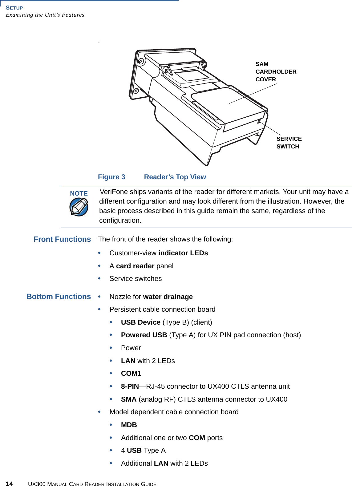
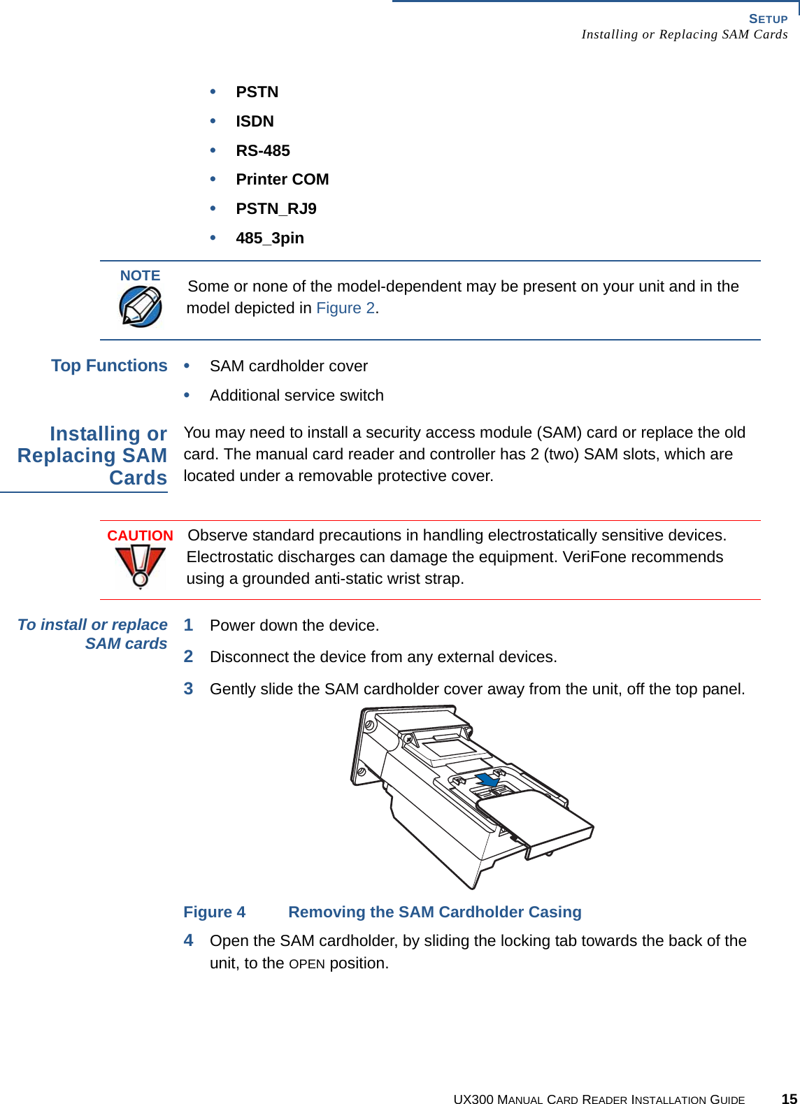
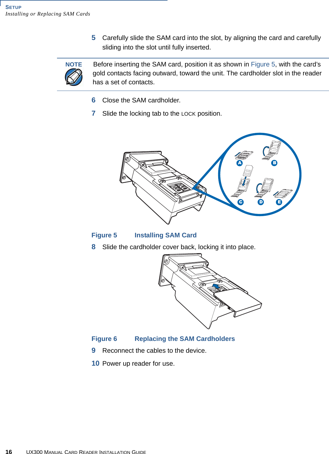
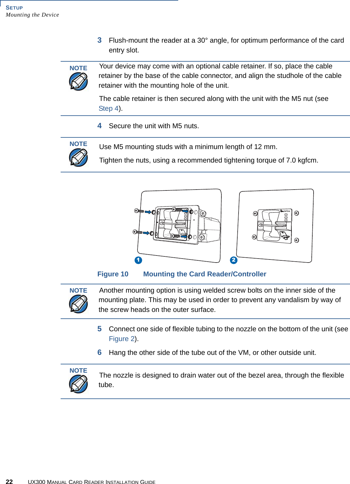
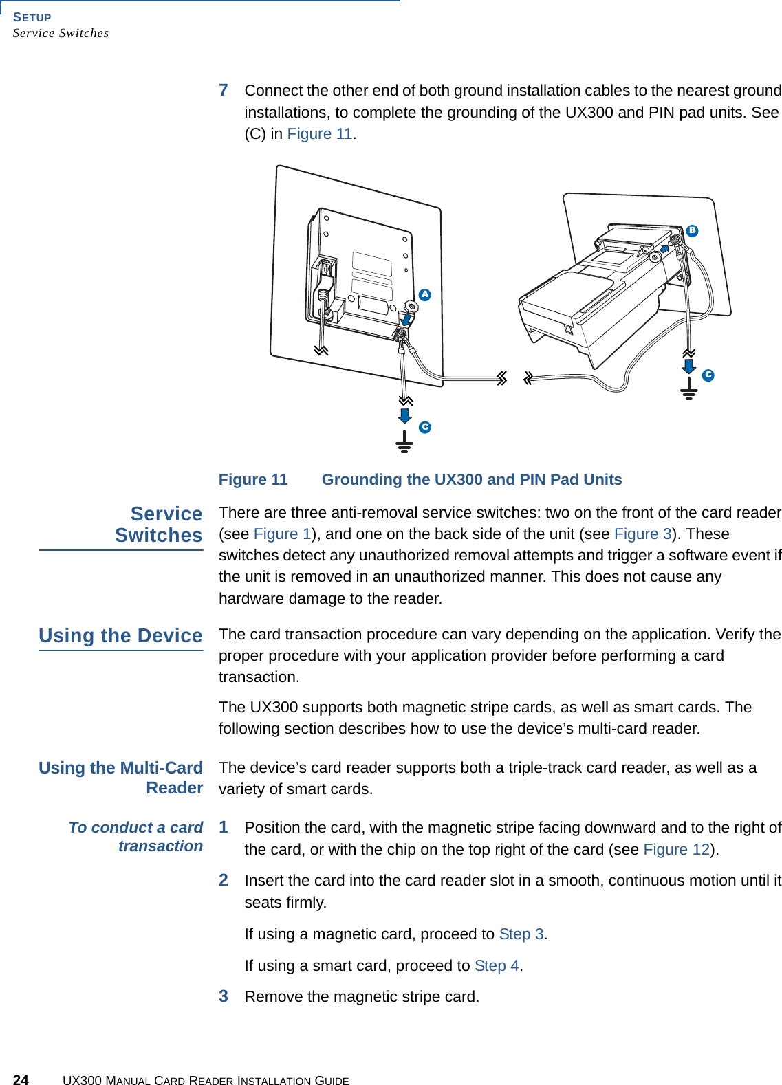
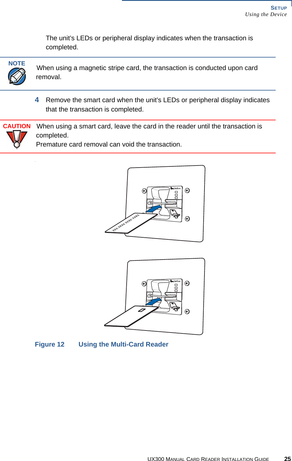
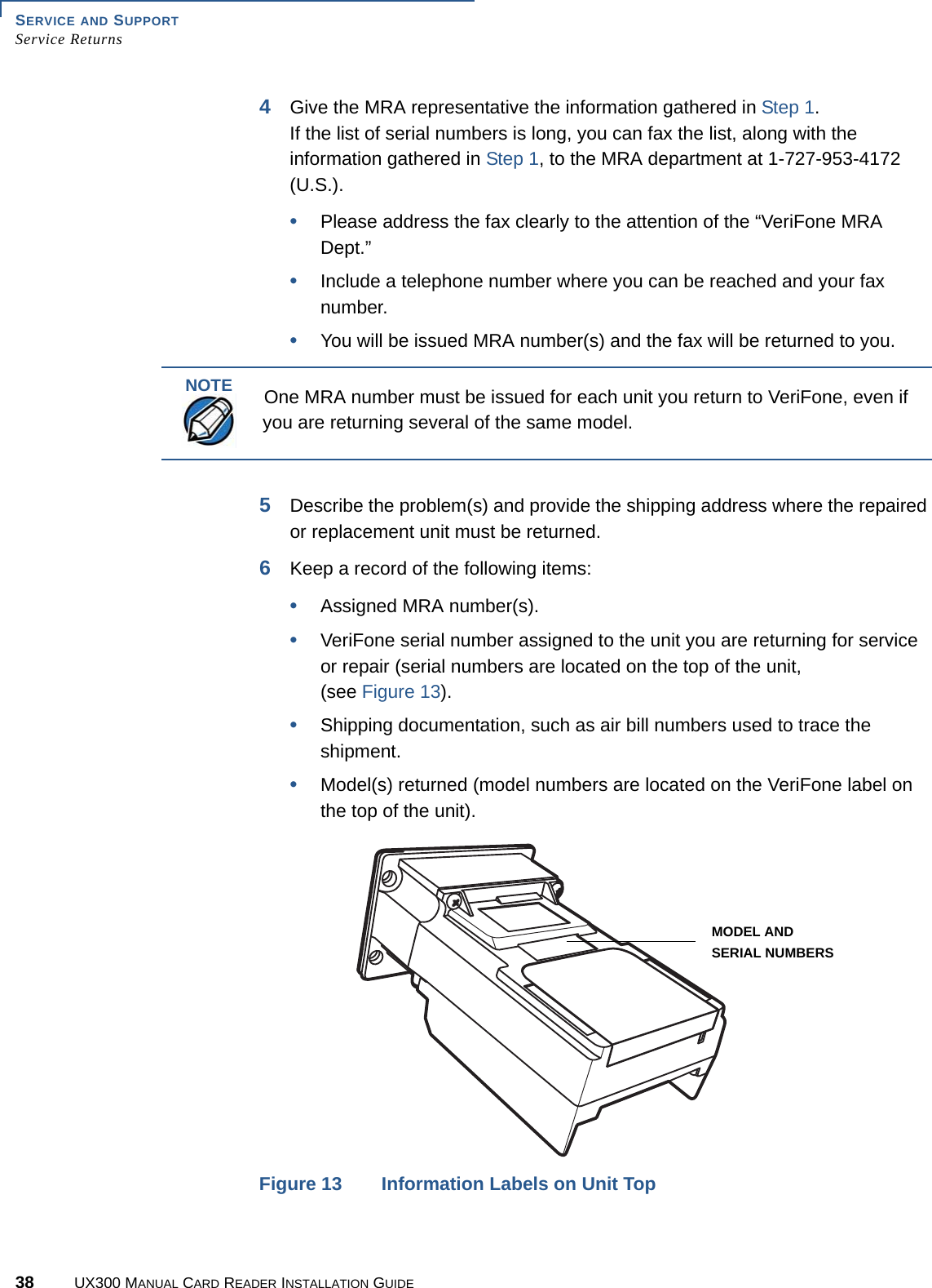
UX300_USER MSNUAL
Contents
1.
UX300_USER MSNUAL
2.
UX400_USER MSNUAL
UX300_USER MSNUAL
Navigation menu
Upload a User Manual
Namespaces
Wiki Guide
HTML
PDF
Info
Views
User Manual
Discussion / Help
Navigation