Contents
- 1. UX300_USER MSNUAL
- 2. UX400_USER MSNUAL
UX300_USER MSNUAL

VeriFone Part Number DOC159-023-EN-A, Revision A.5
UX300 Manual Card Reader
Installation Guide
All rights reserved. No part of the contents of this document may be reproduced or transmitted in any form without the written
permission of VeriFone, Inc.
The information contained in this document is subject to change without notice. Although VeriFone has attempted to ensure the
accuracy of the contents of this document, this document may include errors or omissions. The examples and sample programs are
for illustration only and may not be suited for your purpose. You should verify the applicability of any example or sample program
before placing the software into productive use. This document, including without limitation the examples and software programs, is
supplied “As-Is.”
VeriFone, Inc.
2099 Gateway Place, Suite 600
San Jose, CA, 95110 USA
www.verifone.com
VeriFone Part Number DOC159-023-EN-A, Revision A.5
UX300 Manual Card Reader Installation Guide
© 2013 VeriFone, Inc.
VeriFone, the VeriFone logo, Omni, VeriCentre, Verix, and ZonTalk are registered trademarks of VeriFone. Other brand names or
trademarks associated with VeriFone’s products and services are trademarks of VeriFone, Inc.
All other brand names and trademarks appearing in this manual are the property of their respective holders.
Comments? Please e-mail all comments on this document to your local VeriFone Support Team.

UX300 MANUAL CARD READER INSTALLATION GUIDE 3
CONTENTS
PREFACE . . . . . . . . . . . . . . . . . . . . . . . . . . . . . . . . . . . . . . . 5
Audience. . . . . . . . . . . . . . . . . . . . . . . . . . . . . . . . . . . . . . . . . . . . . . . . . . . . . . . . 5
Organization . . . . . . . . . . . . . . . . . . . . . . . . . . . . . . . . . . . . . . . . . . . . . . . . . . . . . 5
Related Documentation . . . . . . . . . . . . . . . . . . . . . . . . . . . . . . . . . . . . . . . . . . . . 6
Conventions and Acronyms . . . . . . . . . . . . . . . . . . . . . . . . . . . . . . . . . . . . . . . . . 7
Document Conventions. . . . . . . . . . . . . . . . . . . . . . . . . . . . . . . . . . . . . . . . . . 7
Acronym Definitions . . . . . . . . . . . . . . . . . . . . . . . . . . . . . . . . . . . . . . . . . . . . 8
Device Overview Features and Benefits . . . . . . . . . . . . . . . . . . . . . . . . . . . . . . . . . . . . . . . . . . . . . 9
Exceptional Ease of Use. . . . . . . . . . . . . . . . . . . . . . . . . . . . . . . . . . . . . . . . . 9
Compliance. . . . . . . . . . . . . . . . . . . . . . . . . . . . . . . . . . . . . . . . . . . . . . . . . . . 9
Device Capabilities . . . . . . . . . . . . . . . . . . . . . . . . . . . . . . . . . . . . . . . . . . . . 10
Setup Selecting Unit Location. . . . . . . . . . . . . . . . . . . . . . . . . . . . . . . . . . . . . . . . . . . . 11
Environmental Factors . . . . . . . . . . . . . . . . . . . . . . . . . . . . . . . . . . . . . . . . . 11
Unpacking the Shipping Carton . . . . . . . . . . . . . . . . . . . . . . . . . . . . . . . . . . . . . 12
Examining the Unit’s Features . . . . . . . . . . . . . . . . . . . . . . . . . . . . . . . . . . . . . . 13
Front Functions. . . . . . . . . . . . . . . . . . . . . . . . . . . . . . . . . . . . . . . . . . . . . . . 15
Bottom Functions . . . . . . . . . . . . . . . . . . . . . . . . . . . . . . . . . . . . . . . . . . . . . 15
Top Functions . . . . . . . . . . . . . . . . . . . . . . . . . . . . . . . . . . . . . . . . . . . . . . . . 15
Installing or Replacing SAM Cards. . . . . . . . . . . . . . . . . . . . . . . . . . . . . . . . . . . 16
Cable Connections . . . . . . . . . . . . . . . . . . . . . . . . . . . . . . . . . . . . . . . . . . . . . . . 18
Connecting to a UX-Series Host Device. . . . . . . . . . . . . . . . . . . . . . . . . . . . 18
Connecting to a UX-Series Peripheral Device . . . . . . . . . . . . . . . . . . . . . . . 19
Connecting to Other Optional Devices . . . . . . . . . . . . . . . . . . . . . . . . . . . . . 21
Disconnecting Cables . . . . . . . . . . . . . . . . . . . . . . . . . . . . . . . . . . . . . . . . . . 21
Power Supply . . . . . . . . . . . . . . . . . . . . . . . . . . . . . . . . . . . . . . . . . . . . . . . . . . . 22
External Power Connections. . . . . . . . . . . . . . . . . . . . . . . . . . . . . . . . . . . . . 22
Mounting the Device. . . . . . . . . . . . . . . . . . . . . . . . . . . . . . . . . . . . . . . . . . . . . . 24
Grounding the Reader . . . . . . . . . . . . . . . . . . . . . . . . . . . . . . . . . . . . . . . . . . . . 26
Service Switches . . . . . . . . . . . . . . . . . . . . . . . . . . . . . . . . . . . . . . . . . . . . . . . . 27
Using the Device . . . . . . . . . . . . . . . . . . . . . . . . . . . . . . . . . . . . . . . . . . . . . . . . 28
Using the Multi-Card Reader . . . . . . . . . . . . . . . . . . . . . . . . . . . . . . . . . . . . 28
Specifications Unit Power Requirements. . . . . . . . . . . . . . . . . . . . . . . . . . . . . . . . . . . . . . . 31
Power Consumption . . . . . . . . . . . . . . . . . . . . . . . . . . . . . . . . . . . . . . . . . . . 31
Temperature . . . . . . . . . . . . . . . . . . . . . . . . . . . . . . . . . . . . . . . . . . . . . . . . . 31
External Dimensions. . . . . . . . . . . . . . . . . . . . . . . . . . . . . . . . . . . . . . . . . . . 32
Weight. . . . . . . . . . . . . . . . . . . . . . . . . . . . . . . . . . . . . . . . . . . . . . . . . . . . . . 32
Memory. . . . . . . . . . . . . . . . . . . . . . . . . . . . . . . . . . . . . . . . . . . . . . . . . . . . . 32
Magnetic Stripe Card . . . . . . . . . . . . . . . . . . . . . . . . . . . . . . . . . . . . . . . . . . 32
Smart Card Reader. . . . . . . . . . . . . . . . . . . . . . . . . . . . . . . . . . . . . . . . . . . . 32
SAM Requirements. . . . . . . . . . . . . . . . . . . . . . . . . . . . . . . . . . . . . . . . . . . . 32
Peripheral Ports . . . . . . . . . . . . . . . . . . . . . . . . . . . . . . . . . . . . . . . . . . . . . . 32
Communication. . . . . . . . . . . . . . . . . . . . . . . . . . . . . . . . . . . . . . . . . . . . . . . 33
Display . . . . . . . . . . . . . . . . . . . . . . . . . . . . . . . . . . . . . . . . . . . . . . . . . . . . . 33
Maintenance and
Cleaning Additional Safety Information . . . . . . . . . . . . . . . . . . . . . . . . . . . . . . . . . . . . . . . 35
Potentially Explosive Environments . . . . . . . . . . . . . . . . . . . . . . . . . . . . . . . 35
Service and Support Service Returns . . . . . . . . . . . . . . . . . . . . . . . . . . . . . . . . . . . . . . . . . . . . . . . . . 37

CONTENTS
4UX300 MANUAL CARD READER INSTALLATION GUIDE
Accessories and Documentation . . . . . . . . . . . . . . . . . . . . . . . . . . . . . . . . . . . . 39
Connection Cables . . . . . . . . . . . . . . . . . . . . . . . . . . . . . . . . . . . . . . . . . . . . 39
Power Cables . . . . . . . . . . . . . . . . . . . . . . . . . . . . . . . . . . . . . . . . . . . . . . . . 40
Grounding Cables. . . . . . . . . . . . . . . . . . . . . . . . . . . . . . . . . . . . . . . . . . . . . 40
Drainage Tubing . . . . . . . . . . . . . . . . . . . . . . . . . . . . . . . . . . . . . . . . . . . . . . 40
Cleaning Kit. . . . . . . . . . . . . . . . . . . . . . . . . . . . . . . . . . . . . . . . . . . . . . . . . . 40
Documentation . . . . . . . . . . . . . . . . . . . . . . . . . . . . . . . . . . . . . . . . . . . . . . . 41
Troubleshooting
Guidelines Transactions Fail To Process. . . . . . . . . . . . . . . . . . . . . . . . . . . . . . . . . . . . . . . 43
Reader Does Not Dial Out . . . . . . . . . . . . . . . . . . . . . . . . . . . . . . . . . . . . . . . . . 44

UX300 MANUAL CARD READER INSTALLATION GUIDE 5
PREFACE
This guide is the primary source of information for setting up and installing the
UX300 Manual Card Reader unit.
Audience
This guide describes the card reader’s features, and provides the basic
information for its installation and configuration.
Organization
This guide is organized as follows:
Chapter 1, Device Overview. Provides an overview of the device.
Chapter 2, Setup. Explains setup and installation of the device, selecting a
location, and establishing connections with other devices.
Chapter 3, Specifications. Discusses the power requirements and dimensions of
the device.
Chapter 4, Maintenance and Cleaning. Explains maintenance of the device.
Chapter 5, Service and Support. Provides information on contacting your
VeriFone service provider and information on how to order accessories or
documentations from VeriFone.
Chapter 6, Troubleshooting Guidelines. Provides troubleshooting guidelines
should you encounter a problem with unit installation and configuration.

PREFACE
Related Documentation
6UX300 MANUAL CARD READER INSTALLATION GUIDE
Related
Documentation
To learn more about the card reader and controller device, refer to the following
set of documents and their associated VeriFone Part Numbers (VPNs).
UX1XX PIN Pad Series Certifications and Regulations
Sheet
VPN - DOC159-001-EN-A
UX1XX PIN Pad Series Quick Installation Guide VPN - DOC159-002-EN-A
UX1XX PIN Pad Series Installation Guide VPN - DOC159-003-EN-A
UX1XX PIN Pad Series Reference Guide VPN - DOC159-004-EN-A
UX200 Media Display Certifications and Regulations
Sheet
VPN - DOC159-011-EN-A
UX200 Media Display Quick Installation Guide VPN - DOC159-012-EN-A
UX200 Media Display Installation Guide VPN - DOC159-013-EN-A
UX200 Media Display Reference Guide VPN - DOC159-014-EN-A
UX300 Manual Card Reader Certifications and
Regulations Sheet
VPN - DOC159-021-EN-A
UX300 Manual Card Reader Quick Installation Guide VPN - DOC159-022-EN-A
UX300 Manual Card Reader Reference Guide VPN - DOC159-024-EN-A
UX400 CTLS Reader Certifications and Regulations
Guide
VPN - DOC159-031-EN-A
UX400 CTLS Reader Quick Installation Guide VPN - DOC159-032-EN-A
UX400 CTLS Reader Installation Guide VPN - DOC159-033-EN-A
UX400 CTLS Reader Reference Guide VPN - DOC159-034-EN-A
PREFACE
Conventions and Acronyms
UX300 MANUAL CARD READER INSTALLATION GUIDE 7
Conventions and
Acronyms
This section describes the conventions and acronyms used in this guide.
Document
Conventions
Various conventions are used to help you quickly identify special formatting.
Table 1 describes these conventions and provides examples of their use.
Table 1 Document Conventions
Convention Meaning Example
Blue Text in blue indicates terms that
are cross referenced.
See Conventions and
Acronyms.
The pencil icon is used to
highlight important information.
If exchanging cables, use a
VeriFone-approved cable.
The caution symbol indicates
possible hardware or software
failure, or loss of data.
Using an incorrectly rated power
supply can damage the unit or
cause it to malfunction.
The lightning symbol is used as
a warning when bodily injury
might occur.
For safety, do not string cables
or cords across a walkway.
NOTE
CAUTION
WARNING

PREFACE
Conventions and Acronyms
8UX300 MANUAL CARD READER INSTALLATION GUIDE
Acronym Definitions
Various acronyms are used in place of the full definition. Table 2 presents
acronyms and their definitions.
Table 2 Acronym Definitions
Acronym Definitions
COM Communications port
CTLS Contactless
CTS Clear to Send
DDRAM Double Data Release Random Access Memory
ETH Ethernet
HW Hardware
ISDN Integrated Services Digital Network
LCD Liquid Crystal Display
LED Light Emitting Diodes
MDB Multi-Drop Bus
MRA Merchandise Return Authorization
MSR Magnetic Stripe Card Reader
NAND-flash A non-volatile storage technology
PCI Payment Card Industry
PIN Personal Identification Number
POS Point-Of-Sale
PSTN Public Switched Telephone Network
PTS PIN Transaction Security
RF Radio Frequency
RJ-45 Registered Jack 45 modular connector
RS-232 Recommended Standard 232 (EIA standard for transmitting
serial data)
RTS Request to Send
SAM Secure Access Module
SMA SubMiniature version A connector. A semi-precision coaxial RF
connector. See RF.
SRED Secure Reading and Exchange of Data
USB Universal Serial Bus
VM Vending Machine
WAN Wide Area Networks

UX300 MANUAL CARD READER INSTALLATION GUIDE 9
CHAPTER 1
Device Overview
This chapter provides a brief description of VeriFone’s UX300 Manual Card
Reader.
The device is a card reader processing device that works with the UX1XX
PIN pads, UX400 CTLS antenna unit, UX200 display, vending machines, PCs,
and other similar peripheral devices. The device can also connect to VeriFone’s
TG-2460 printer, as well as other VeriFone PIN pad units. The reader supports
transactions in a variety of environments, specifically in the outdoor and
unattended markets.
Features and
Benefits
The UX300 is VeriFone’s card reader and main control unit. It creates an
economical solution for merchants who are looking to expand their payment
acceptance options.
Exceptional Ease of
Use
The following features of the device simplifies transactions in various
environments:
•Device driver installs USB connections automatically.
•Designed for indoor and outdoor use.
•Sleep mode.
•Various connectivity options integrated into device to conveniently suit most
unattended environments.
•Connects with various VeriFone unattended POS terminals.
•Bright LEDs to display card transaction progress.
•Buzzer for audio confirmation of card transactions.
•Conducive design supports payment transactions in a variety of payment
situations, such as transportation, vending, and kiosk environments.
Compliance
PCI PTS 3.1, PCI-SRED, EMV Level 1 and Level 2, PayPass, PayWave, and
AMEX Expresspay2.
NOTE
The implementation of the LED color configuration varies by (or may not be
present in some) regional locations.

DEVICE OVERVIEW
Features and Benefits
10 UX300 MANUAL CARD READER INSTALLATION GUIDE
Device Capabilities
The UX300 is a magnetic card reader, smart card reader, as well as a main
control unit device. This unit connects to vending machines and PCs, and is
intended to connect to peripheral units such as PIN pad, CTLS antenna, media
display units, and external printers.

SETUP
Unpacking the Shipping Carton
12 UX300 MANUAL CARD READER INSTALLATION GUIDE
Unpacking the
Shipping Carton
Open the shipping carton and carefully inspect its contents for possible tampering
or shipping damage.
To unpack the
shipping carton 1Remove the unit from the shipping carton. The standard package contains the
unit only and does not include any other cables or accessories. Refer to
Accessories and Documentation for more information about the device’s
related accessories.
2Remove any protective wrap before mounting the unit.
3Save the shipping carton and packing material for future repacking or moving
of the device.
WARNING
Do not use a unit that appears to be damaged.
If a label or component appears damaged, please notify the shipping company
and your VeriFone service provider immediately.
SETUP
Examining the Unit’s Features
UX300 MANUAL CARD READER INSTALLATION GUIDE 13
Examining the
Unit’s Features
Before you continue the installation process, notice the features of the device (see
Figure 1, Figure 2, and Figure 3).
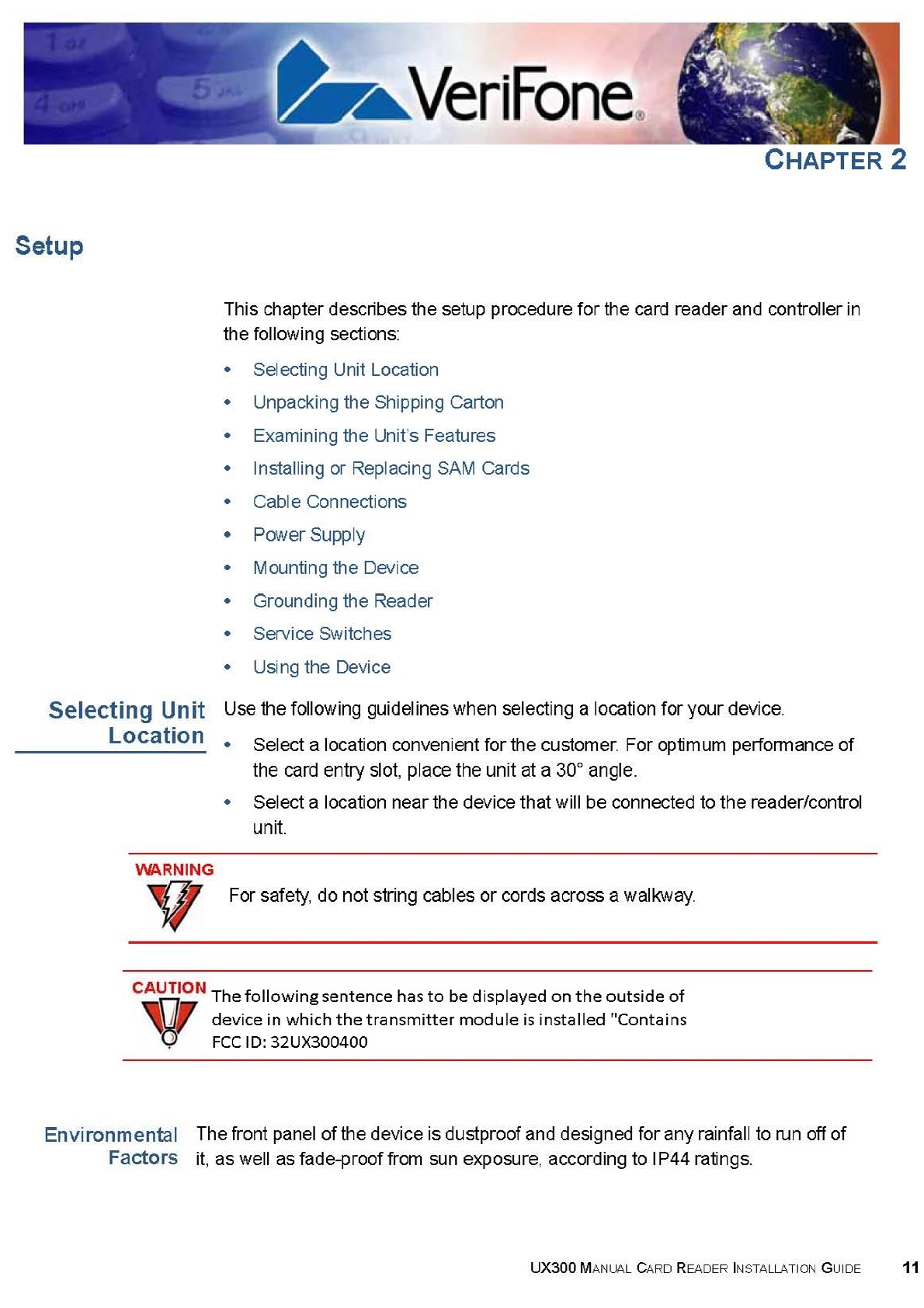
Figure 1 Reader’s Front View
Figure 2 Reader’s Bottom View
MAGNETIC STRIPE CARD
AND SMART CARD READER
LEDS
MOUNTING STUD HOLES
MOUNTING STUD HOLES
SERVICE SWITCH SERVICE SWITCH
MDB
POWERED USB
(HOST)
COM2 AND 3
485–RJ9
485– 3-PIN
USB DEVICE
(CLIENT)
POWERED USB
(HOST)
POWER
LAN
SMA
8-PIN RF
MODEL DEPENDENT
BOARD
COM1
PERSISTENT
BOARD
NOZZLE
SETUP
Examining the Unit’s Features
14 UX300 MANUAL CARD READER INSTALLATION GUIDE
.
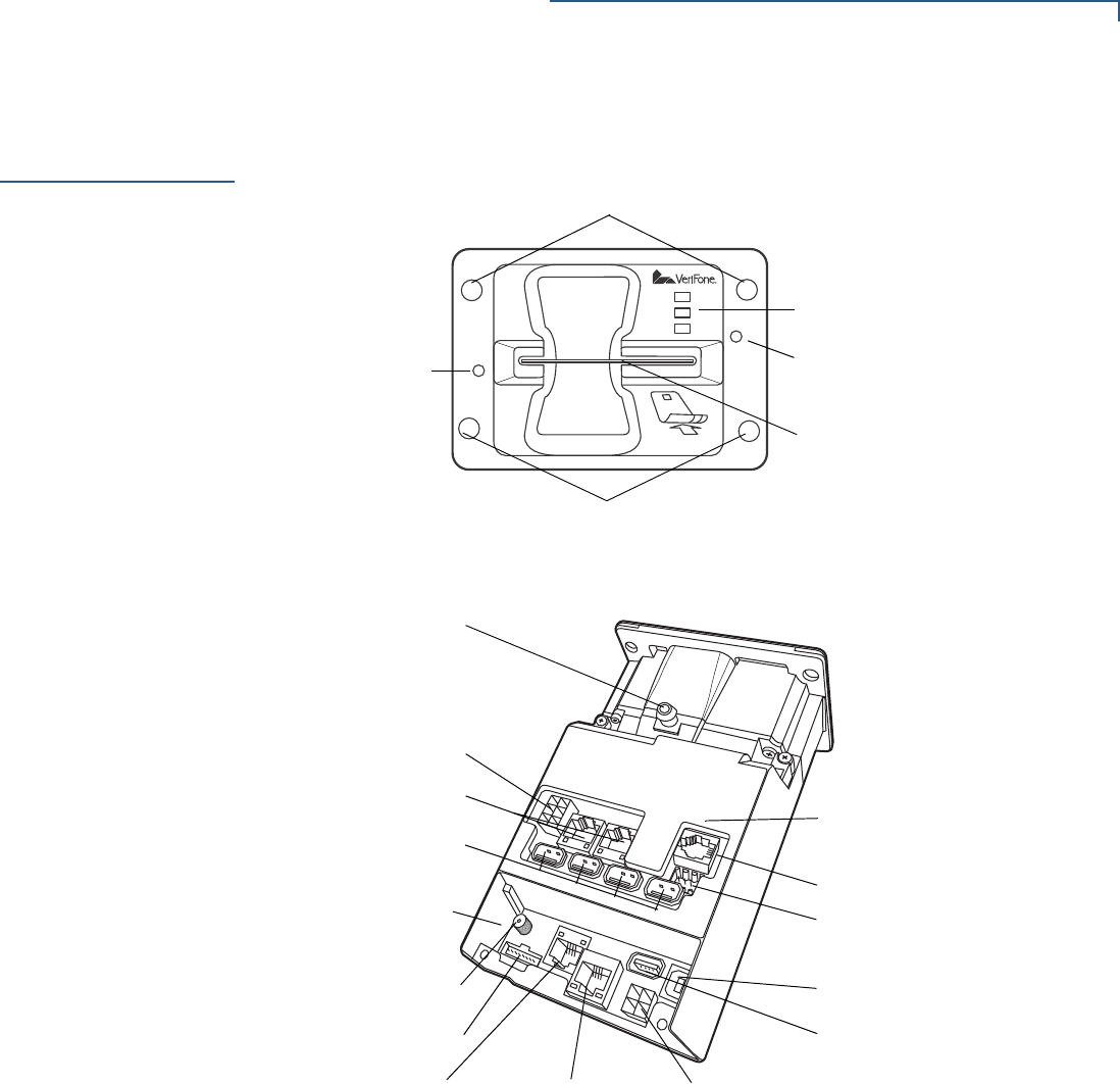
Figure 3 Reader’s Top View
Front Functions
The front of the reader shows the following:
•Customer-view indicator LEDs
•A card reader panel
•Service switches
Bottom Functions
•Nozzle for water drainage
•Persistent cable connection board
•USB Device (Type B) (client)
•Powered USB (Type A) for UX PIN pad connection (host)
•Power
•LAN with 2 LEDs
•COM1
•8-PIN—RJ-45 connector to UX400 CTLS antenna unit
•SMA (analog RF) CTLS antenna connector to UX400
•Model dependent cable connection board
•MDB
•Additional one or two COM ports
•4 USB Type A
•Additional LAN with 2 LEDs
SAM
CARDHOLDER
COVER
SERVICE
SWITCH
NOTE
VeriFone ships variants of the reader for different markets. Your unit may have a
different configuration and may look different from the illustration. However, the
basic process described in this guide remain the same, regardless of the
configuration.
SETUP
Installing or Replacing SAM Cards
UX300 MANUAL CARD READER INSTALLATION GUIDE 15
•PSTN
•ISDN
•RS-485
•Printer COM
•PSTN_RJ9
•485_3pin
Top Functions
•SAM cardholder cover
•Additional service switch
Installing or
Replacing SAM
Cards
You may need to install a security access module (SAM) card or replace the old
card. The manual card reader and controller has 2 (two) SAM slots, which are
located under a removable protective cover.
To install or replace
SAM cards 1Power down the device.
2Disconnect the device from any external devices.
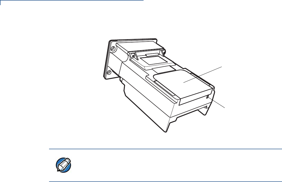
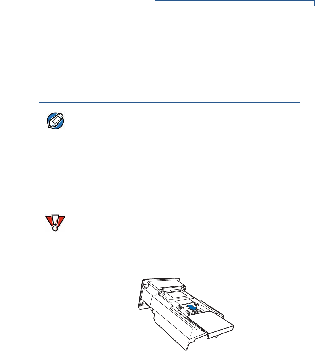
3Gently slide the SAM cardholder cover away from the unit, off the top panel.
Figure 4 Removing the SAM Cardholder Casing
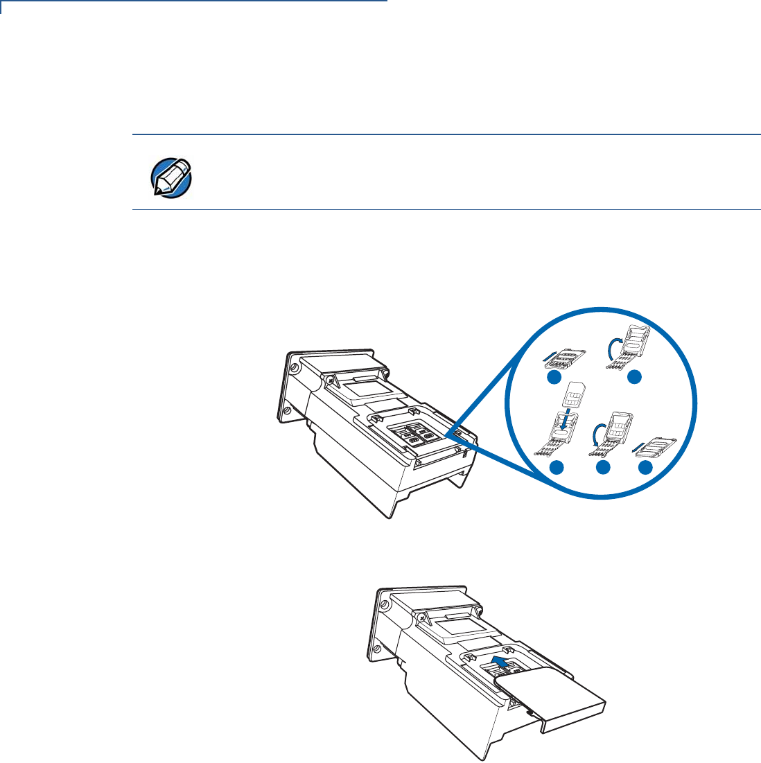
4Open the SAM cardholder, by sliding the locking tab towards the back of the
unit, to the OPEN position.
NOTE
Some or none of the model-dependent may be present on your unit and in the
model depicted in Figure 2.
CAUTION
Observe standard precautions in handling electrostatically sensitive devices.
Electrostatic discharges can damage the equipment. VeriFone recommends
using a grounded anti-static wrist strap.
SETUP
Installing or Replacing SAM Cards
16 UX300 MANUAL CARD READER INSTALLATION GUIDE
5Carefully slide the SAM card into the slot, by aligning the card and carefully
sliding into the slot until fully inserted.
6Close the SAM cardholder.
7Slide the locking tab to the LOCK position.
Figure 5 Installing SAM Card
8Slide the cardholder cover back, locking it into place.
Figure 6 Replacing the SAM Cardholders
9Reconnect the cables to the device.
10 Power up reader for use.
NOTE
Before inserting the SAM card, position it as shown in Figure 5, with the card’s
gold contacts facing outward, toward the unit. The cardholder slot in the reader
has a set of contacts.
EDC
B
A

SETUP
Cable Connections
UX300 MANUAL CARD READER INSTALLATION GUIDE 17
Cable
Connections
The device’s rear panel has various interface ports for power and communication
connections to controlling and peripheral devices. This section discusses these
various connections.
The UX300 card reader/control unit connects to the various UX-series units, as
well as other devices.
This section discusses how to connect to each of the units:
•Connecting to a UX-Series Host Device
•Connecting to a UX-Series Peripheral Device
•Connecting to Other Optional Devices
Connecting to a UX-
Series Host Device
This section discusses the connection of the UX300 device with the following host
units:
•Connecting to a Vending Machine
•Connecting to a UX200 Media Display Host Unit
•Connecting to a PC
Connecting to a Vending Machine
The UX300 unit is designed to connect to a host vending machine. Connect to a
host VM, through any of one of these four connection types:
•MDB
•USB Type B
•ETH (LAN)
•COM (RS-232)
Connect the appropriate cable to the UX300 unit and the other end to the vending
machine.
Connecting to a UX200 Media Display Host Unit
The UX300 unit is designed to connect to the host UX200 media display. Connect
to the display through any one of these two connection types:
•USB Type B
•ETH (LAN)
NOTE
To attain or replace connection cables, see Accessories and Documentation.
SETUP
Cable Connections
18 UX300 MANUAL CARD READER INSTALLATION GUIDE
Connect the appropriate cable to the UX300 unit and the other end to the media
display.
Connecting to a PC
The UX300 unit is designed to connect to a host PC through one of three
connection ports:
•RJ-45–-RS-232 connection
•USB Type B connection
•LAN connection
Connect the appropriate cable to the UX300 unit and the other end to the PC unit.
For more information regarding your card reader configuration and your cabling
needs, contact your local VeriFone service provider. For cable ordering
information, see Accessories and Documentation).
Connecting to a UX-
Series Peripheral
Device
This section discusses the connection of the UX300 device with the following
peripheral units:
•Connecting to a UX1XX PIN Pad
•Connecting to a UX200 Media Display Unit
•Connecting to a UX400 CTLS Unit
Connecting to a
UX1XX PIN Pad
The UX300 unit is designed to connect to a UX1XX PIN pad device through a
standard USB Type A connection.
Connect the USB cable to the UX300 unit and the other end to the PIN pad.
For further cabling instructions, see Figure 7.
Figure 7 Connecting to a UX Series PIN Pad
NOTE
The UX300 connects to the UX200 media display as both a host, as well as a
peripheral device. To see how to connect to the UX200 as a peripheral device,
see Connecting to a UX-Series Peripheral Device.
SETUP
Cable Connections
UX300 MANUAL CARD READER INSTALLATION GUIDE 19
Connecting to a UX200 Media Display Unit
The UX300 unit is designed to connect to a UX200 media display. Connect to the
peripheral display unit through any one of these two connection types:
•USB Type A
•ETH (LAN)
Connect the appropriate cable to the UX300 unit and the other end to the media
display.
For more information regarding your card reader configuration and your cabling
needs, contact your local VeriFone service provider. For cable ordering
information, see Accessories and Documentation).
Connecting to a UX400 CTLS Unit
The UX300 unit is designed to connect to a UX400 contactless unit using an
8-pin—RJ-45 connector and an SMA connector.
To connect the UX300
to the UX400 CTLS
unit
1Connect the 8-pin connector to the UX300 unit.
2Connect the RJ-45 plug to the rear of the contactless unit.
3Screw in the SMA connector to the UX300 unit.
4Screw in the SMA connector to the rear of the contactless unit.
5Connect the RF antenna cable to the UX300 unit and the other end to the
CTLS unit and screw tightly by hand.
For further cabling instructions, see Figure 8.
Figure 8 Connecting to a UX400 CTLS Unit
Connecting to Other
Optional Devices
The UX300 device can connect to various peripheral devices, outside of the UX-
Series product range. Such products include:
•Connecting to a Printer
NOTE
The UX300 connects to the UX200 media display as both a peripheral device, as
well as a host unit. To see how to connect to the UX200 as a host unit, see
Connecting to a UX-Series Host Device.
RJ-45
SMA
SMA
UX300
8-Pin

SETUP
Power Supply
20 UX300 MANUAL CARD READER INSTALLATION GUIDE
•Connecting to A VeriFone PIN Pad
Connecting to a Printer
The UX300 unit is designed to connect to an external printer, such as VeriFone’s
TG2460 printer, using a COM connection.
Connect one end of the RS-232 cable to the UX300 printer port and the other end
to the printer.
Connecting to A VeriFone PIN Pad
The UX300 unit is designed to connect to other VeriFone PIN pads. Connect to
the PIN pad through any one of two connection types:
•USB Type A
•ETH (LAN)
Connect the appropriate cable to the UX300 unit and the other end to the
PIN pad.
Disconnecting
Cables
To disconnect cables, use the same steps described above in reverse. If
exchanging cables, use a VeriFone-approved cable. See Accessories and
Documentation for cable ordering information.
Power Supply
Not all UX300 configurations and device contexts require the use of a power
supply. VeriFone ships power supplies with the UX300 as required.
If you have changed the context in which the UX300 is used or have questions
about which power supply should be used, contact your VeriFone representative.
For more information, see Accessories and Documentation.
Before connecting a power supply, disconnect the power pack cord from the
power outlet.
Connect and route all cables between the UX300 and any peripheral units before
plugging the power pack cord into a wall outlet or surge protector.
CAUTION
Using an incorrectly rated power supply can damage the unit or cause it to
malfunction. The power rating as listed for the various unit types is as follows:
•MDB, LAN, PSTN, and ISDN units: 9V DC to 43V DC, 4.4A
•Standard unit: 9V DC to 12V DC, 1.6A
•Petrol unit: 24V DC, 3.7A
Use only a power pack with VPN PWR159-001-01-A or CPS12490-4A-R. See
Specifications for detailed power supply specifications.
WARNING
Disconnecting power during a transaction can cause transaction data files not yet
stored in memory to be lost.
SETUP
Mounting the Device
UX300 MANUAL CARD READER INSTALLATION GUIDE 21
External Power
Connections
The UX300 connects to an external power outlet through a 4-pin interconnect
cable (VPN - CBL159-308-01-A) or a 6-pin interconnect cable
(CBL159-309-01-A). The connection depends on your specific card reader
configuration.
For more information regarding your card reader configuration, contact your local
VeriFone service provider. For cable ordering information, see Accessories and
Documentation).
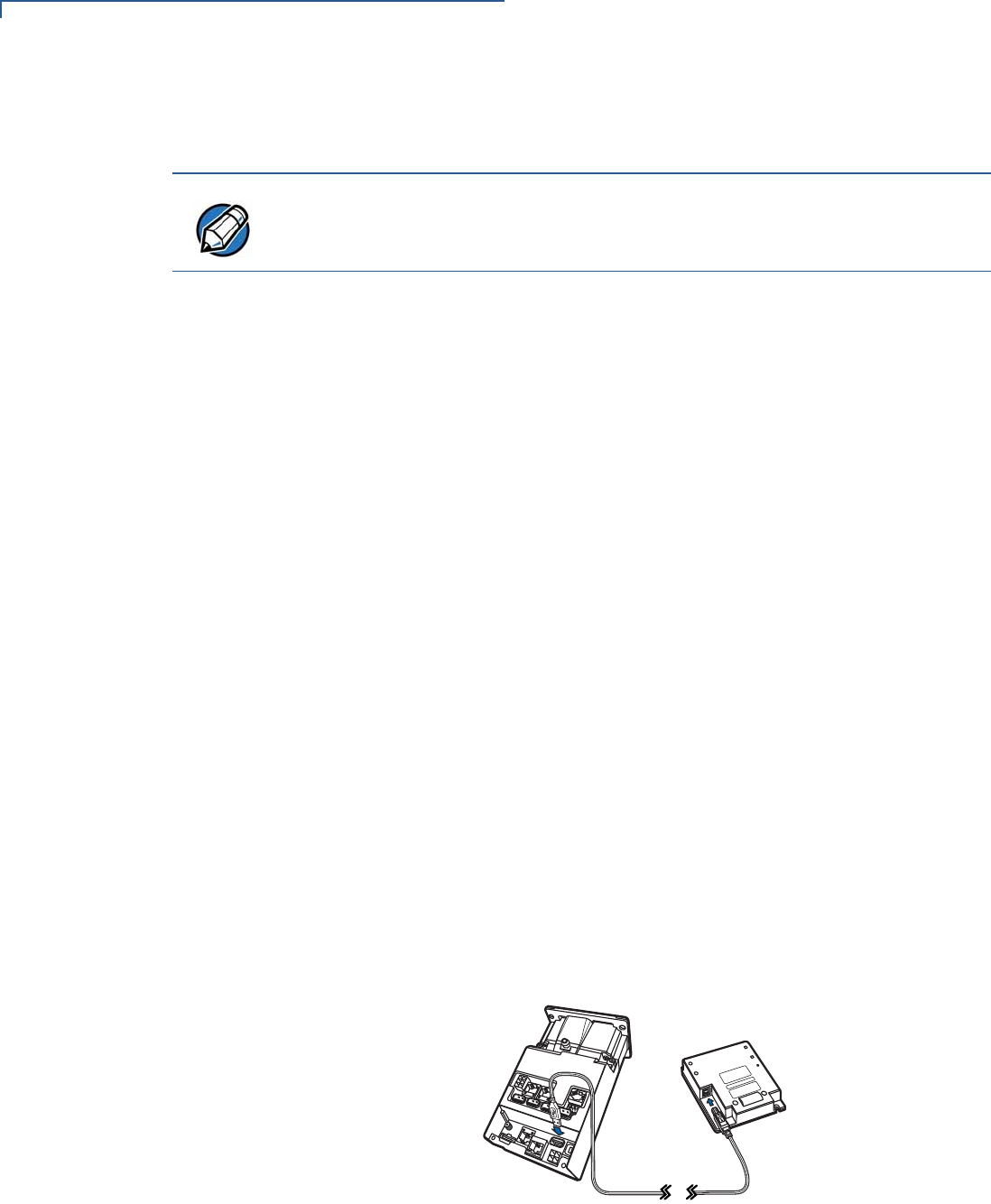
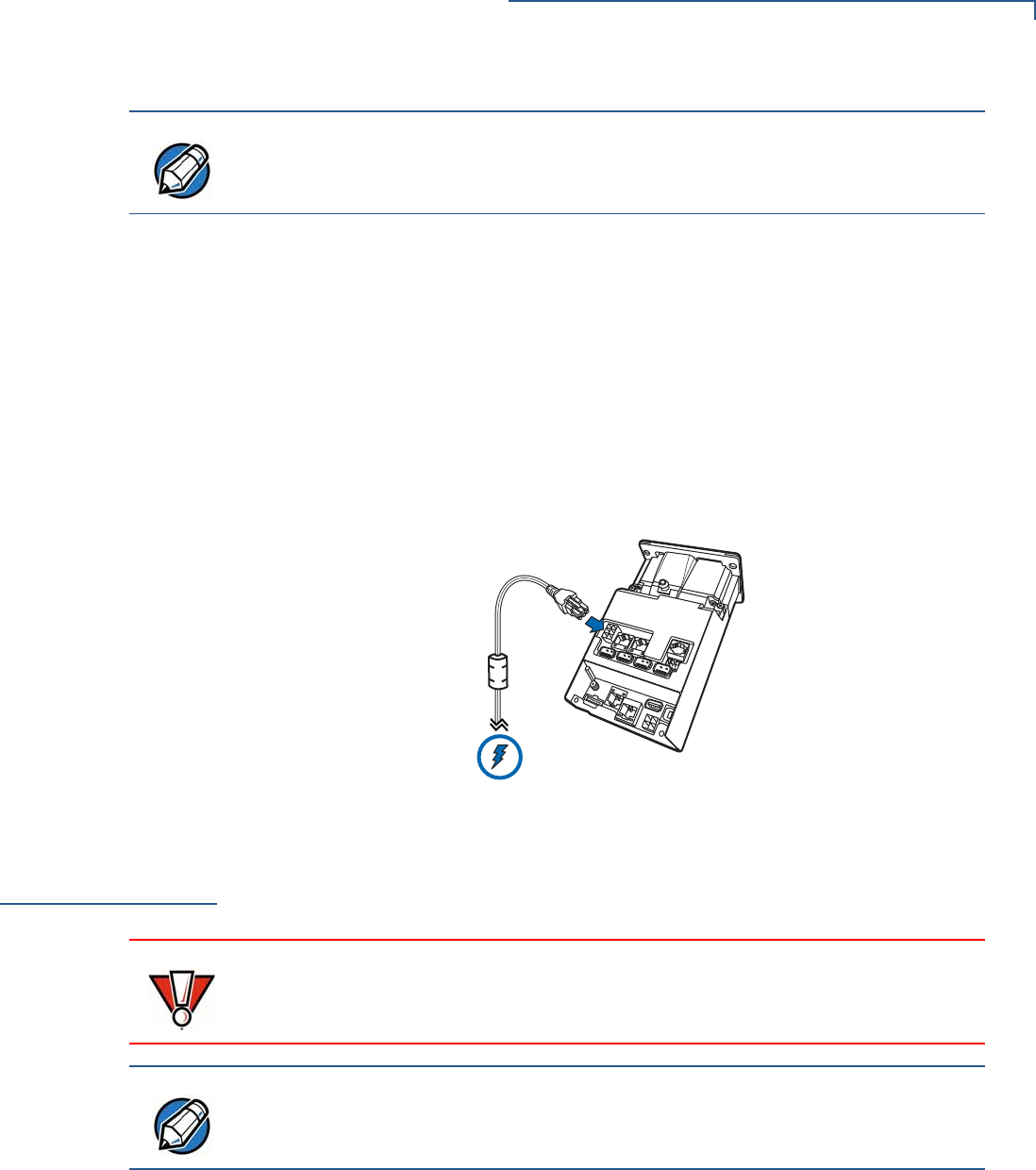
To connect to an
external power outlet Connect the 4- or 6-pin interconnect cable to the external power port on your
device and the other end to an external power outlet.
Figure 9 Sample Connection to an External Power Source
Mounting the
Device
The card reader and controller is designed to be flush-mounted to the mounting
surface, without further need for any external mounting devices.
To mount the unit 1Peel off the plastic liner from the front of the unit.
2Align the reader’s stud holes with the holes of your mounting surface.
NOTE
To protect against possible damage caused by lightning strikes and electrical
surges, VeriFone recommends installing a power surge protector.
CAUTION
For proper operation of the security switches, no additional gaskets or washers
may be used, except for the ones provided to you.
Ensure that your mounting frame has a thickness of 2 mm.
NOTE
Your mounting surface may have different installation instructions. Refer to your
mounting device’s user guide for further instructions.
SETUP
Mounting the Device
22 UX300 MANUAL CARD READER INSTALLATION GUIDE
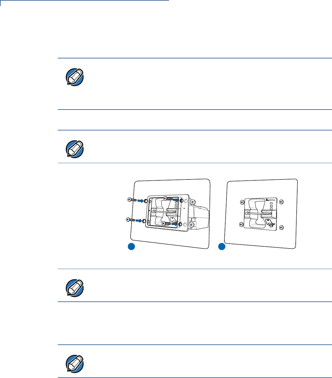
3Flush-mount the reader at a 30° angle, for optimum performance of the card
entry slot.
4Secure the unit with M5 nuts.
Figure 10 Mounting the Card Reader/Controller
5Connect one side of flexible tubing to the nozzle on the bottom of the unit (see
Figure 2).
6Hang the other side of the tube out of the VM, or other outside unit.
NOTE
Your device may come with an optional cable retainer. If so, place the cable
retainer by the base of the cable connector, and align the studhole of the cable
retainer with the mounting hole of the unit.
The cable retainer is then secured along with the unit with the M5 nut (see
Step 4).
NOTE
Use M5 mounting studs with a minimum length of 12 mm.
Tighten the nuts, using a recommended tightening torque of 7.0 kgfcm.
1 2
NOTE
Another mounting option is using welded screw bolts on the inner side of the
mounting plate. This may be used in order to prevent any vandalism by way of
the screw heads on the outer surface.
NOTE
The nozzle is designed to drain water out of the bezel area, through the flexible
tube.
SETUP
Grounding the Reader
UX300 MANUAL CARD READER INSTALLATION GUIDE 23
Grounding the
Reader
When the reader is connected to one of the UX-series PIN pads, it is important to
ground your units.
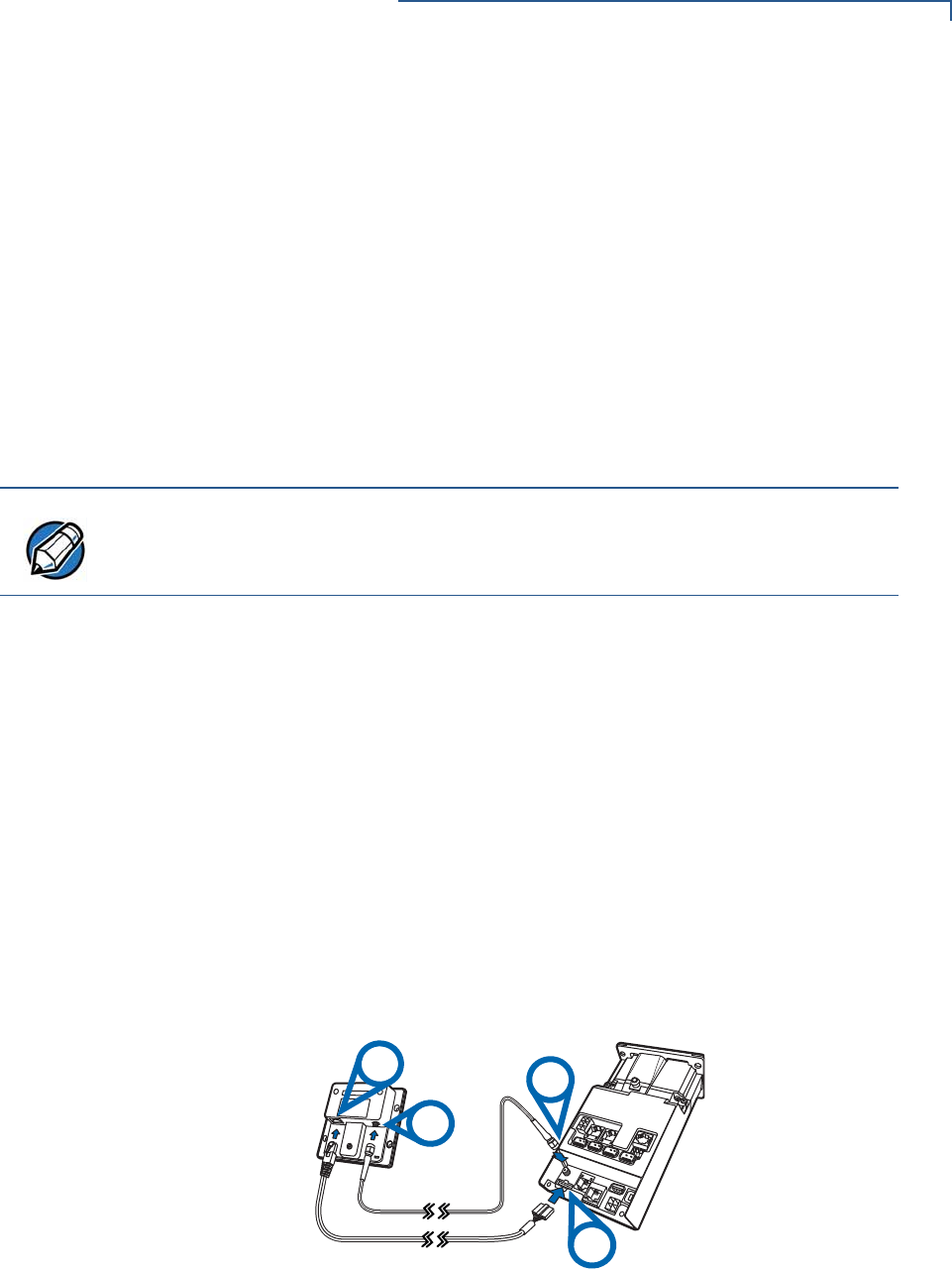
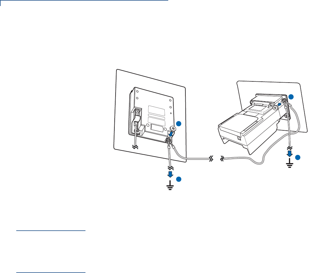
To ground the reader 1Remove a nut, exposing a stud from the back of the PIN pad unit (do not use
the one from the cable retainer). See (A) in .Figure 11.
2Attach the grounding cable to the UX300 (P/N WIR159-302-01-A) and the
grounding cable to a ground installation. See (A) in Figure 11.
3Tighten the nut, to secure the PIN pad.
4Remove a nut, exposing a stud from the back of the UX300 unit.
5On the UX300 unit stud, attach the other end of the grounding cable from the
PIN pad (P/N WIR159-302-01-A) and the grounding cable to a ground
installation (P/N WIR159-302-02-A). See (B) in Figure 11.
6Tighten the nut, to secure the UX300 device.
NOTE
For cable use and ordering information, see Accessories and Documentation.
NOTE
To tighten the nuts, using a recommended tightening torque of 7.0 kgfcm.
NOTE
Tighten the nuts, using a recommended tightening torque of 7.0 kgfcm.
SETUP
Service Switches
24 UX300 MANUAL CARD READER INSTALLATION GUIDE
7Connect the other end of both ground installation cables to the nearest ground
installations, to complete the grounding of the UX300 and PIN pad units. See
(C) in Figure 11.
Figure 11 Grounding the UX300 and PIN Pad Units
Service
Switches
There are three anti-removal service switches: two on the front of the card reader
(see Figure 1), and one on the back side of the unit (see Figure 3). These
switches detect any unauthorized removal attempts and trigger a software event if
the unit is removed in an unauthorized manner. This does not cause any
hardware damage to the reader.
Using the Device
The card transaction procedure can vary depending on the application. Verify the
proper procedure with your application provider before performing a card
transaction.
The UX300 supports both magnetic stripe cards, as well as smart cards. The
following section describes how to use the device’s multi-card reader.
Using the Multi-Card
Reader
The device’s card reader supports both a triple-track card reader, as well as a
variety of smart cards.
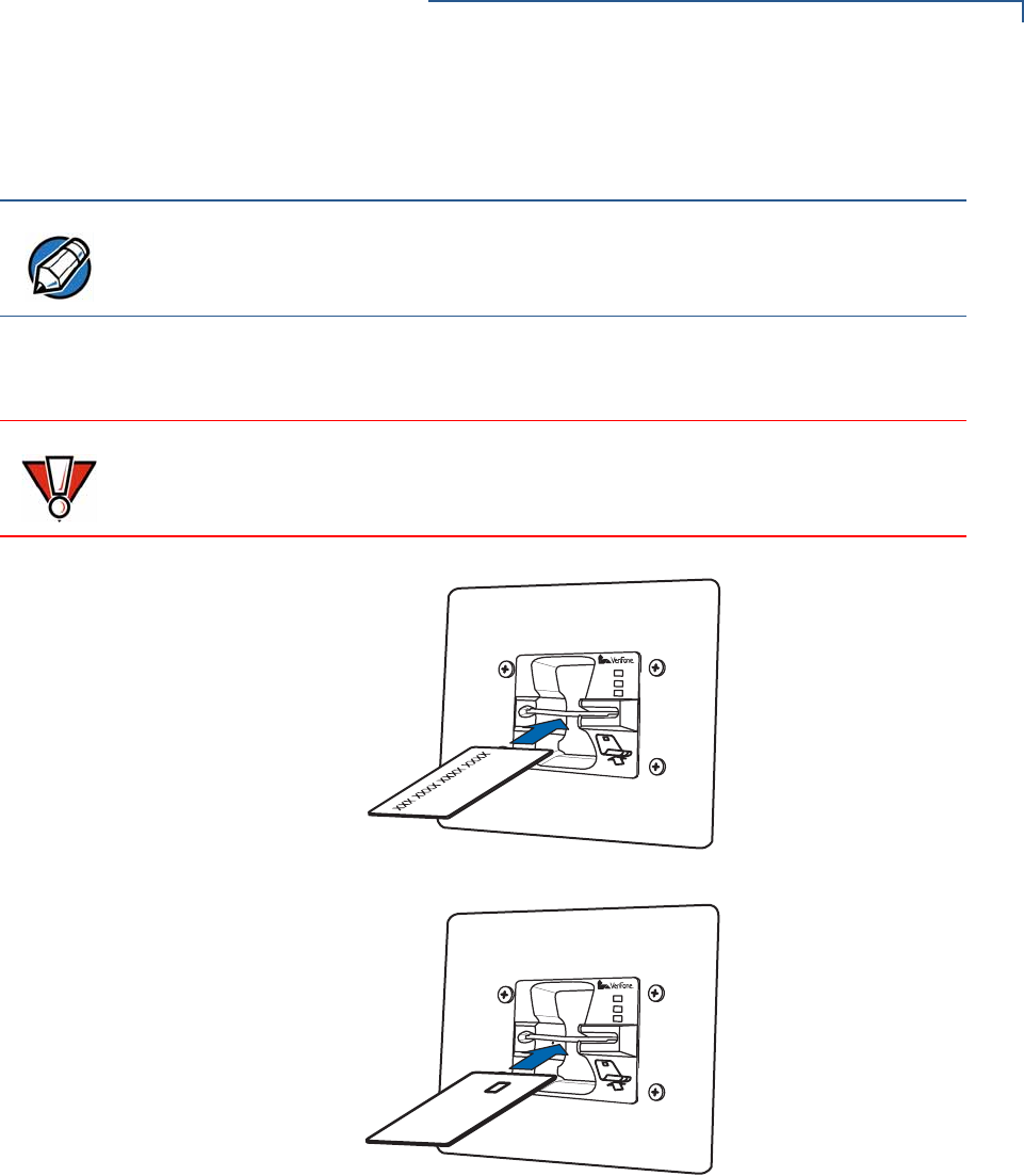
To conduct a card
transaction 1Position the card, with the magnetic stripe facing downward and to the right of
the card, or with the chip on the top right of the card (see Figure 12).
2Insert the card into the card reader slot in a smooth, continuous motion until it
seats firmly.
If using a magnetic card, proceed to Step 3.
If using a smart card, proceed to Step 4.
3Remove the magnetic stripe card.
B
A
C
C
SETUP
Using the Device
UX300 MANUAL CARD READER INSTALLATION GUIDE 25
The unit’s LEDs or peripheral display indicates when the transaction is
completed.
4Remove the smart card when the unit’s LEDs or peripheral display indicates
that the transaction is completed.
.
.
Figure 12 Using the Multi-Card Reader
NOTE
When using a magnetic stripe card, the transaction is conducted upon card
removal.
CAUTION
When using a smart card, leave the card in the reader until the transaction is
completed.
Premature card removal can void the transaction.

SETUP
Using the Device
26 UX300 MANUAL CARD READER INSTALLATION GUIDE

UX300 MANUAL CARD READER INSTALLATION GUIDE 31
CHAPTER 3
Specifications
This chapter discusses power requirements, dimensions, and other specifications
of the card reader.
Unit Power
Requirements
•MDB, LAN, PSTN, and ISDN units:
•Operation voltage: 9V DC to 43V DC, 4.4A
•Fully optically isolated serial current loop: 9600 bps
•Standard unit:
•Operation voltage: 9V DC to 12V DC, 1.6A
•Petrol unit:
•Operation voltage: 24V DC, 3.7A
•External Power Supply:
•12V DC, 3.3A
or
•24V DC, 3.75A
•Power Supply:
•12V DC 3.3A
•24V DC 3.75A
Temperature
•Indoor operating temperature: -20°C – 70°C (-4°F – 158°F)
•Indoor storage temperature: -25°C – 70°C (-13°F – 158°F)
•Outdoor operating temperature: -20°C – 60°C (-4°F – 140°F)
•Outdoor storage temperature: -25°C – 60°C (-13°F – 140°F)
•Relative humidity: 5% to 90% RH non-condensing
External
Dimensions
•Height: 72 mm (2.83 in)
•Width: 96 mm (3.78 in)
NOTE
If this device is to be used in the Nordic countries, or in any environment where
the temperature range exceeds the product’s operating temperature, it is the
responsibility of the integrators to ensure that the ambient environment is
controlled in such a way to ensure that the product operates within the specified
temperature range.

SPECIFICATIONS
32 UX300 MANUAL CARD READER INSTALLATION GUIDE
•Depth 150 mm (5.9 in)
Weight
•Unit weight:750 g (26.46 oz)
Memory
•128 MB DDRAM
•256 MB NAND-Flash
Magnetic Stripe
Card
•Bi-directional reader
•Triple-track
Smart Card Reader
•Non-sliding
•Card conserving plated landing contacts
SAM Requirements
•2 SAM slots
Peripheral Ports
•Consistent ports:
•Power
•Powered USB Type A for UX PIN pads (host)
•USB Type B (client)
•COM1 (powered)
•ETH (LAN) connection with 2 colored LEDs for link state and speed
indication
•Analog RF CTLS antenna connector to the UX400 CTLS unit
•8-PIN–RJ-45 connector to UX400 CTLS antenna unit
Model dependent cable connection board:
•4 Powered USB Type A
•MDB
•Additional 1 or 2 COM powered ports
•ISDN
•PSTN
•RS-485
•An additional ETH connection with 2 colored LEDs for link state and speed
indication
•Printer COM
•PSTN_RJ9
•485_3pin
Communication
•COM: Up to 115200 HW RTS/CTS handshake
•MDB: 9600 bps fix, 9E1

SPECIFICATIONS
UX300 MANUAL CARD READER INSTALLATION GUIDE 33
•RS485: Up to 115200 bps, half duplex
Display
•3 status LEDs on the front (payment application controlled)

SPECIFICATIONS
34 UX300 MANUAL CARD READER INSTALLATION GUIDE

UX300 MANUAL CARD READER INSTALLATION GUIDE 35
CHAPTER 4
Maintenance and Cleaning
Your card reader is a product of superior design and craftsmanship and should be
treated with care. It has no user-serviceable parts.
The following suggestions will help you protect your warranty coverage.
•Do not store the device in hot areas. High temperatures can shorten the
life of electronic devices, damage batteries, and warp or melt certain
plastics.
•Do not store the device in cold areas. When the device returns to its
normal temperature, moisture can form inside the device and damage
electronic circuit boards.
•Do not drop, knock, or shake the device. Rough handling can break
internal circuit boards and fine mechanics.
•Do not use harsh chemicals, cleaning solvents, or strong detergents to
clean the device. Use only a soft, clean, dry cloth for cleaning.
These suggestions apply equally to your device, or any of its attachments or
accessories. If your device is not working properly, take it to the nearest VeriFone-
authorized service provider for servicing or replacement.
Additional
Safety
Information
The following is additional information for your safety in using this device.
Potentially
Explosive
Environments
When using the device in areas with potential risk of explosion, such as petrol
stations, follow the advice of all signs and instructions. If there has been a leak, do
not use this device.
CAUTION
Never use thinner, trichloroethylene, or ketone-based solvents – they can
deteriorate plastic or rubber parts.

MAINTENANCE AND CLEANING
Additional Safety Information
36 UX300 MANUAL CARD READER INSTALLATION GUIDE

UX300 MANUAL CARD READER INSTALLATION GUIDE 37
CHAPTER 5
Service and Support
For UX300 problems, contact your local VeriFone representative or service
provider.
For device product service and repair information:
•USA – VeriFone Service and Support Group, 1-800-834-4366,
Monday - Friday, 8 A.M. - 8 P.M., eastern time.
•International – Contact your VeriFone representative.
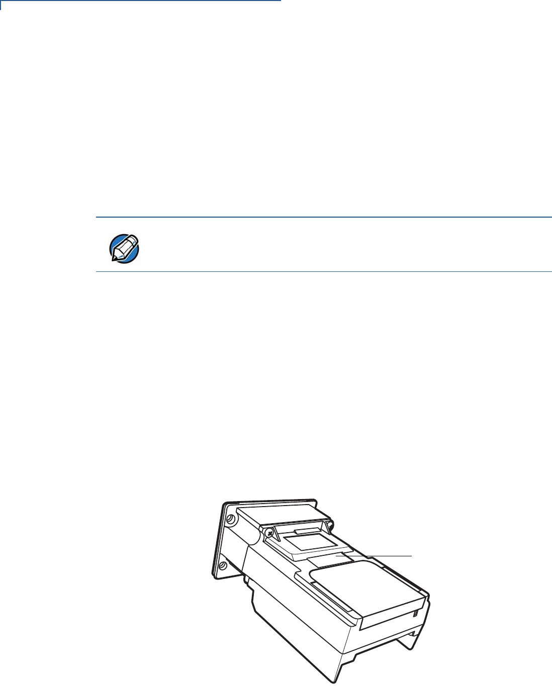
Service Returns
Before returning the unit to VeriFone, you must obtain a Merchandise Return
Authorization (MRA) number. The following procedure describes how to return
one or more card reading units for repair or replacement (U.S. customers only).
1Gather the following information from the printed labels (see Figure 13) on the
bottom of each unit to be returned:
•Product ID, including the model and part number. For example,
“M159-300-xx-WWB” and “PTID xxxxxxxx.”
•Serial number (S/N xxx-xxx-xxx).
2Within the United States, call VeriFone toll-free at 1-800-834-4366.
3Select the MRA option from the automated message. The MRA department is
open Monday–Friday, 8 A.M.–8 P.M., eastern time.
NOTE
International customers, please contact your local VeriFone representative for
assistance with your service, return, or replacement.
SERVICE AND SUPPORT
Service Returns
38 UX300 MANUAL CARD READER INSTALLATION GUIDE
4Give the MRA representative the information gathered in Step 1.
If the list of serial numbers is long, you can fax the list, along with the
information gathered in Step 1, to the MRA department at 1-727-953-4172
(U.S.).
•Please address the fax clearly to the attention of the “VeriFone MRA
Dept.”
•Include a telephone number where you can be reached and your fax
number.
•You will be issued MRA number(s) and the fax will be returned to you.
5Describe the problem(s) and provide the shipping address where the repaired
or replacement unit must be returned.
6Keep a record of the following items:
•Assigned MRA number(s).
•VeriFone serial number assigned to the unit you are returning for service
or repair (serial numbers are located on the top of the unit,
(see Figure 13).
•Shipping documentation, such as air bill numbers used to trace the
shipment.
•Model(s) returned (model numbers are located on the VeriFone label on
the top of the unit).
Figure 13 Information Labels on Unit Top
NOTE
One MRA number must be issued for each unit you return to VeriFone, even if
you are returning several of the same model.
SERIAL NUMBERS
MODEL AND

SERVICE AND SUPPORT
Accessories and Documentation
UX300 MANUAL CARD READER INSTALLATION GUIDE 39
Accessories and
Documentation
VeriFone produces accessories and documentation for the card reader. When
ordering, please refer to the part number in the left column.
VeriFone Online Store at www.store.verifone.com
•USA – VeriFone Customer Development Center, 1-800-834-4366,
Monday - Friday, 7 A.M. - 8 P.M., eastern time
•International – Contact your VeriFone representative
Connection Cables
The following cables can be used with the card reader. Contact your local
VeriFone distributor to determine which cable fits your needs:
Various others, depending on what they connect to. Contact your local
VeriFone representative or service provider to identify the best cable for your
needs.
CAB-00123-L Powered USB Type A connection to peripheral
devices.
xxxxxx USB Type B connection for Host connections
CBL159-302-02-X SMA (RF) connector to UX400 CTLS unit
CBL159-301-01-X 8-PIN–RJ-45 connector to UX400 CTLS unit
xxxxxxx MDB connection to VMs
xxxxxxx RS-485 connection
xxxxxxxx WAN connections
CBL159-305-01-X RS232 to RJ45 connector. For connection to
TG2460 printer.
CBL000-045-01-A USB Type A-B cable for UX1xx connection
26264-02-R COM-DB9 cable for connecting UX300 controlling
device.
CBL159-312-01-A LAN cable for Ethernet connections

SERVICE AND SUPPORT
Accessories and Documentation
40 UX300 MANUAL CARD READER INSTALLATION GUIDE
Power Cables
The following power cables can be used with the card reader. Contact your local
VeriFone distributor to determine which cable fits your needs:
Grounding Cables
The following grounding cables are to be used with the card reader, when
connecting to a PIN pad unit. Contact your local VeriFone distributor for further
information:
Drainage Tubing
Cleaning Kit
Documentation
CBL159-308-01-A 4-pin connection cable to external power
supply
CBL159-309-01-A 6-pin connection cable to external power
supply
PWR159-001-01-A Power pack for indoor power supply
CPS12490-4A-R Power pack for outdoor power supply
CBL159-306-01-X Y power cable for external power connection
for TG2460 printer.
CBL159-307-01-X Interconnect PWR cable from CBL159-309-01-
X to TRACO PWR cable 27556-10-R for
printer external power.
WIR159-302-01-A 1 meter PIN pad–UX300 grounding cable
WIR159-302-02-A 2.5 meter grounding cables
XXXXXXX Flexible tubing for water drainage.
02746 VeriFone Cleaning Kit
UX1XX PIN Pad Series Certifications and Regulations
Sheet
VPN - DOC159-001-EN-A
UX1XX PIN Pad Series Quick Installation Guide VPN - DOC159-002-EN-A
UX1XX PIN Pad Series Installation Guide VPN - DOC159-003-EN-A
UX1XX PIN Pad Series Reference Guide VPN - DOC159-004-EN-A
UX200 Media Display Certifications and Regulations
Sheet
VPN - DOC159-011-EN-A
UX200 Media Display Quick Installation Guide VPN - DOC159-012-EN-A
UX200 Media Display Installation Guide VPN - DOC159-013-EN-A
UX200 Media Display Reference Guide VPN - DOC159-014-EN-A

SERVICE AND SUPPORT
Accessories and Documentation
UX300 MANUAL CARD READER INSTALLATION GUIDE 41
UX300 Manual Card Reader Certifications and
Regulations Sheet
VPN - DOC159-021-EN-A
UX300 Manual Card Reader Quick Installation Guide VPN - DOC159-022-EN-A
UX300 Manual Card Reader Reference Guide VPN - DOC159-024-EN-A
UX400 CTLS Reader Certifications and Regulations
Guide
VPN - DOC159-031-EN-A
UX400 CTLS Reader Quick Installation Guide VPN - DOC159-032-EN-A
UX400 CTLS Reader Installation Guide VPN - DOC159-033-EN-A
UX400 CTLS Reader Reference Guide VPN - DOC159-034-EN-A

SERVICE AND SUPPORT
Accessories and Documentation
42 UX300 MANUAL CARD READER INSTALLATION GUIDE
UX300 MANUAL CARD READER INSTALLATION GUIDE 43
CHAPTER 6
Troubleshooting
Guidelines
This chapter lists possible malfunctions that may occur while operating a UX300
device and the appropriate corrective action. if the problem persists - even after
performing the outlined guidelines, or if the problem is not described, contact your
local VeriFone representative for assistance.
Transactions
Fail To Process
There are several reasons why the card reader may not be processing
transactions. Use the following steps to troubleshoot failures.
Check the Magnetic Card Reader
•Perform a test transaction using one or more different magnetic stripe cards to
ensure the problem is not a defective card.
•Ensure that you are swiping cards properly. With the card reader, the black
magnetic stripe should face down and outward, toward the outside of the
reader.
•If possible, process a transaction manually, using an external keypad, instead
of the card reader. If the manual transaction works, the problem may be a
defective reader.
•If the problem persists, contact your local VeriFone representative.
Check the Smart Card Reader
•Perform a test transaction using several different smart cards to ensure the
problem is not a defective card.
NOTE
The unit comes equipped with tamper-evident labels. The reader contains no
user-serviceable parts. Do not, under any circumstance, attempt to disassemble
the unit. Perform only those adjustments or repairs specified in this guide. For all
other services, contact your local VeriFone service provider. Service conducted
by parties other than authorized VeriFone representatives may void any warranty.
CAUTION
Not all units require use of a power supply.
Using an incorrectly rated power supply may damage the unit or cause it not to
work properly. Before troubleshooting, ensure that the power supply used to
power the unit matches the requirements specified on the back of the unit (see
Specifications for detailed power supply specifications). If not, obtain the
appropriately rated power supply before continuing with troubleshooting.

TROUBLESHOOTING GUIDELINES
Transactions Fail To Process
44 UX300 MANUAL CARD READER INSTALLATION GUIDE
•Ensure that the card is inserted correctly and that the card is not removed
prematurely.
•Ensure the SAM cards are properly inserted in the cardholders and that the
cardholders are properly secured (see Installing or Replacing SAM Cards).
•If the problem persists, contact your local VeriFone representative.


*DOC159-031-EN-A*
c 2013 VeriFone, Inc. All rights reserved.
2099 Gateway Place, Suite 600
San Jose CA 95110
Tel: 800 VeriFone (837-4366)
www.verifone.com
UX400 CTLS Reader Certifications and Regulations
VeriFone Part Number: DOC159-031-EN-A Revision A
Electrical
The reference input power rating for the UX400 CTLS Reader is 450mW max.
Location – Electrical Considerations
Do not install this device near electrical appliances or other devices that cause excessive voltage fluctuations or emit electrical
noise (for example: air conditioners, neon signs, electric motors, high-frequency or magnetic security devices).
WARNING! This device contains sensitive electronic components that can be permanently damaged if exposed to excessive
shock, electrical interference or vibration.
Equipment
Repairs
Do not, under any circumstances, attempt any service, adjustments, or repairs on this equipment. Instead, contact your local
VeriFone distributor or service provider for assistance. Failure to comply may void the product warranty.
Damage
Carefully inspect the shipping carton and its contents for any damage. If the UX400 CTLS Reader or any product component
appears damaged or tampered, immediately notify the shipping company and your VeriFone distributor or service provider.
Do not use a device that has been damaged or tampered with.
Cleaners and Solvents
Never use thinner, trichloroethylene, or ketone-based solvents to clean the device — they may deteriorate the plastic and rubber
parts. For best results, use a clean cloth dampened with water and mild soap. To remove stubborn stains, use alcohol or an alcohol-
based cleaner.
UX400 CTLS Reader Certifications and Regulations
FCC Compliance
The following product has been tested and certified as compliant with the regulations and guidelines set forth in Part 15 of FCC
Rules:
Manufacturer: VeriFone, Inc.
Brand, Model: UX400 CTLS Reader
Part 15 of FCC Rules
This device complies with the limits for a Class B digital device as specified in Part 15 of FCC Rules which provide reasonable
protection against harmful interference in a residential area.
This device complies with Part 15 of the FCC Rules.
Operation is subject to the following two conditions:
1This device may not cause harmful interference; and,
2This device must accept any interference received, including interference that may cause undesired operation.
This equipment generates and uses radio frequency energy, and if not installed and used in accordance with the instructions, may
cause harmful interference to radio communications. However, there is no guarantee that interference will not occur in a particular
installation.
In the unlikely event that there is interference to radio or television reception (which can be determined by turning the equipment off
and on), the user is encouraged to try to correct the interference by one or more of the following measures:
• Increase the separation between the equipment and receiver.
• Connect the equipment into an outlet on a circuit different from that to which the receiver is connected.
• Consult with the dealer or ask an experienced radio/TV technician for help.
Any changes or modifications to this equipment not expressly approved by VeriFone could void the user’s authority to operate this
equipment. The antenna(s) used for this transmitter must not be co-located or operating in conjunction with any other antenna or
transmitter. Use of a shielded interface cable is required to comply with the Class B limits of Part 15 of FCC Rules.
RF Exposure
This device was verified for RF exposure. To comply with Council Recommendation 1999/519/EC, IC RSS-102, and FCC RF
exposure requirements, a minimum separation distance of 20 cm must be maintained between the user's body and the device,
including the antenna. Any metallic components should be far from this device. Conditions that do not meet these requirements
may not comply with Council Recommendation 1999/519/EC, IC RSS-102 and FCC RF exposure requirements and should be
avoided.
To comply with the FCC RF exposure compliance requirements, make sure to use only the antenna that is included with the device.
This device and its antenna must not be in the same location or operating in the same area in conjunction with any other antenna or
transmitter.
Legal Terms and Conditions Regarding PCI SSC Approvals
PCI SSC’s approval only applies to PEDs that are identical to the PED tested by a PCI Security Standards Council recognized
laboratory. If any aspect of the PED is different from that which was tested by the laboratory - even if the PED conforms to the basic
product description contained in the letter, then the PED model should not be considered approved, nor promoted as approved. For
example, if a PED contains firmware, software, or physical construction that has the same name or model number as those tested
by the laboratory, but in fact are not identical to those PED samples tested by the laboratory, then the PED should not be
considered or promoted as approved.
No vendor or other third party may refer to a PED as “PCI Approved,” nor otherwise state or imply that PCI SSC has, in whole or
part, approved any aspect of a vendor or its PEDs, except to the extent and subject to the terms and restrictions expressly set forth
in a written agreement with PCI SSC, or in an approval letter. All other references to PCI SSC’s approval are strictly and actively
prohibited by PCI SSC.
When granted, an approval is provided by PCI SSC to ensure certain security and operational characteristics important to the
achievement of PCI SSC’s goals, but the approval does not under any circumstances include any endorsement or warranty
regarding the functionality, quality, or performance of any particular product or service. PCI SSC does not warrant any products or
services provided by third parties. Approval does not, under any circumstances, include or imply any product warranties from PCI
SSC, including, without limitation, any implied warranties of merchantability, fitness for purpose or noninfringement, all of which are
expressly disclaimed by PCI SSC. All rights and remedies regarding products and services, which have received an approval, shall
be provided by the party providing such products or services, and not by PCI SSC or the payment brand participants.
This equipment operates on a secondary basis. It is not entitled to protection from harmful interference, even for stations of the
same type, and may not cause interference to systems operating on a primary basis.
Recycling: DO NOT DISCARD!
UNIT MUST BE RECYCLED OR DISPOSED OF PROPERLY
For proper disposal instructions go to http://recycle.verifone.com/Please retain this sheet for future reference.
continued on rear cover