Contents
- 1. UX300_USER MSNUAL
- 2. UX400_USER MSNUAL
UX400_USER MSNUAL

VeriFone Part Number DOC159-033-EN-A, Revision A.3
UX400 CTLS Reader
Installation Guide
All rights reserved. No part of the contents of this document may be reproduced or transmitted in any form without the written
permission of VeriFone, Inc.
The information contained in this document is subject to change without notice. Although VeriFone has attempted to ensure the
accuracy of the contents of this document, this document may include errors or omissions. The examples and sample programs are
for illustration only and may not be suited for your purpose. You should verify the applicability of any example or sample program
before placing the software into productive use. This document, including without limitation the examples and software programs, is
supplied “As-Is.”
VeriFone, Inc.
2099 Gateway Place, Suite 600
San Jose, CA, 95110 USA
www.verifone.com
VeriFone Part Number DOC159-033-EN-A, Revision A.3
UX400 CTLS Reader Installation Guide
© 2013 VeriFone, Inc.
VeriFone, the VeriFone logo, Omni, VeriCentre, Verix, and ZonTalk are registered trademarks of VeriFone. Other brand names or
trademarks associated with VeriFone’s products and services are trademarks of VeriFone, Inc.
All other brand names and trademarks appearing in this manual are the property of their respective holders.
Comments? Please e-mail all comments on this document to your local VeriFone Support Team.

UX400 CTLS READER INSTALLATION GUIDE 3
CONTENTS
PREFACE . . . . . . . . . . . . . . . . . . . . . . . . . . . . . . . . . . . . . . . 5
Audience. . . . . . . . . . . . . . . . . . . . . . . . . . . . . . . . . . . . . . . . . . . . . . . . . . . . . . . . 5
Organization . . . . . . . . . . . . . . . . . . . . . . . . . . . . . . . . . . . . . . . . . . . . . . . . . . . . . 5
Related Documentation . . . . . . . . . . . . . . . . . . . . . . . . . . . . . . . . . . . . . . . . . . . . 5
Conventions and Acronyms . . . . . . . . . . . . . . . . . . . . . . . . . . . . . . . . . . . . . . . . . 6
Document Conventions. . . . . . . . . . . . . . . . . . . . . . . . . . . . . . . . . . . . . . . . . . 6
Acronym Definitions . . . . . . . . . . . . . . . . . . . . . . . . . . . . . . . . . . . . . . . . . . . . 7
Device Overview Features and Benefits . . . . . . . . . . . . . . . . . . . . . . . . . . . . . . . . . . . . . . . . . . . . . 9
Exceptional Ease of Use. . . . . . . . . . . . . . . . . . . . . . . . . . . . . . . . . . . . . . . . . 9
Compliance. . . . . . . . . . . . . . . . . . . . . . . . . . . . . . . . . . . . . . . . . . . . . . . . . . . 9
Contactless Capabilities . . . . . . . . . . . . . . . . . . . . . . . . . . . . . . . . . . . . . . . . 10
Setup Selecting Reader Location . . . . . . . . . . . . . . . . . . . . . . . . . . . . . . . . . . . . . . . . . 11
Environmental Factors . . . . . . . . . . . . . . . . . . . . . . . . . . . . . . . . . . . . . . . . . 11
Unpacking the Shipping Carton . . . . . . . . . . . . . . . . . . . . . . . . . . . . . . . . . . . . . 12
Examining the CTLS Reader Features. . . . . . . . . . . . . . . . . . . . . . . . . . . . . . . . 13
Front Functions. . . . . . . . . . . . . . . . . . . . . . . . . . . . . . . . . . . . . . . . . . . . . . . 13
Back Functions . . . . . . . . . . . . . . . . . . . . . . . . . . . . . . . . . . . . . . . . . . . . . . . 13
Connecting Unit to a Controlling Device. . . . . . . . . . . . . . . . . . . . . . . . . . . . . . . 14
Contactless Support . . . . . . . . . . . . . . . . . . . . . . . . . . . . . . . . . . . . . . . . . . . . . . 14
Mounting the Reader . . . . . . . . . . . . . . . . . . . . . . . . . . . . . . . . . . . . . . . . . . . . . 15
Using the Reader . . . . . . . . . . . . . . . . . . . . . . . . . . . . . . . . . . . . . . . . . . . . . . . . 16
Conducting a Contactless Transaction . . . . . . . . . . . . . . . . . . . . . . . . . . . . . 16
Specifications Power Requirements . . . . . . . . . . . . . . . . . . . . . . . . . . . . . . . . . . . . . . . . . . 17
Power Consumption . . . . . . . . . . . . . . . . . . . . . . . . . . . . . . . . . . . . . . . . . . . 17
Temperature . . . . . . . . . . . . . . . . . . . . . . . . . . . . . . . . . . . . . . . . . . . . . . . . . 17
External Dimensions. . . . . . . . . . . . . . . . . . . . . . . . . . . . . . . . . . . . . . . . . . . 17
Weight. . . . . . . . . . . . . . . . . . . . . . . . . . . . . . . . . . . . . . . . . . . . . . . . . . . . . . 17
CTLS Card Reader . . . . . . . . . . . . . . . . . . . . . . . . . . . . . . . . . . . . . . . . . . . . 17
Peripheral Ports . . . . . . . . . . . . . . . . . . . . . . . . . . . . . . . . . . . . . . . . . . . . . . 17
Communication. . . . . . . . . . . . . . . . . . . . . . . . . . . . . . . . . . . . . . . . . . . . . . . 17
Maintenance and
Cleaning Additional Safety Information . . . . . . . . . . . . . . . . . . . . . . . . . . . . . . . . . . . . . . . 19
Potentially Explosive Environments . . . . . . . . . . . . . . . . . . . . . . . . . . . . . . . 19
Service and Support Service Returns . . . . . . . . . . . . . . . . . . . . . . . . . . . . . . . . . . . . . . . . . . . . . . . . . 21
Accessories and Documentation . . . . . . . . . . . . . . . . . . . . . . . . . . . . . . . . . . . . 23
Cables. . . . . . . . . . . . . . . . . . . . . . . . . . . . . . . . . . . . . . . . . . . . . . . . . . . . . . 23
Cleaning Kit. . . . . . . . . . . . . . . . . . . . . . . . . . . . . . . . . . . . . . . . . . . . . . . . . . 23
Documentation . . . . . . . . . . . . . . . . . . . . . . . . . . . . . . . . . . . . . . . . . . . . . . . 23
Troubleshooting
Guidelines Transactions Fail to Process . . . . . . . . . . . . . . . . . . . . . . . . . . . . . . . . . . . . . . . 25

CONTENTS
4UX400 CTLS READER INSTALLATION GUIDE

UX400 CTLS READER INSTALLATION GUIDE 5
PREFACE
This guide is the primary source of information for setting up and installing the
UX400 CTLS Reader.
Audience
This guide describes the CTLS reader’s features, and provides the basic
information for its installation and configuration.
Organization
This guide is organized as follows:
Chapter 1, Device Overview. Provides an overview of the reader.
Chapter 2, Setup. Explains setup and installation of the device, selecting a
location, and establishing connections with other devices.
Chapter 3, Specifications. Discusses the power requirements and dimensions of
the CTLS device.
Chapter 4, Maintenance and Cleaning. Explains maintenance of the CTLS device.
Chapter 5, Service and Support. Provides information on contacting your
VeriFone service provider and information on how to order accessories or
documentations from VeriFone.
Chapter 6, Troubleshooting Guidelines. Provides troubleshooting guidelines
should you encounter a problem with unit installation and configuration.
Related
Documentation
To learn more about the reader, refer to the following set of documents and their
associated VeriFone Part Numbers (VPNs).
UX400 CTLS Reader Certifications and Regulations
Sheet
VPN - DOC159-031-EN-A
UX400 CTLS Reader Quick Installation Guide VPN - DOC159-032-EN-A
UX400 CTLS Reader Reference Guide VPN - DOC159-034-EN-A
UX300 Manual Card Reader Certifications and
Regulations Sheet
VPN - DOC159-021-EN-A
UX300 Manual Card Reader Quick Installation Guide VPN - DOC159-022-EN-A
UX300 Manual Card Reader Installation Guide VPN - DOC159-023-EN-A
UX300 Manual Card Reader Reference Guide VPN - DOC159-024-EN-A
PREFACE
Conventions and Acronyms
6UX400 CTLS READER INSTALLATION GUIDE
Conventions and
Acronyms
This section describes the conventions and acronyms used in this guide.
Document
Conventions
Various conventions are used to help you quickly identify special formatting.
Table 1 describes these conventions and provides examples of their use.
Table 1 Document Conventions
Convention Meaning Example
Blue Text in blue indicates terms that
are cross referenced.
See Conventions and
Acronyms.
The pencil icon is used to
highlight important information.
If exchanging cables use a
VeriFone-approved cable.
The caution symbol indicates
possible hardware or software
failure, or loss of data.
Avoid placing metallic objects at
the front of the card reader
The lightning symbol is used as
a warning when bodily injury
might occur.
For safety, do not string cables
or cords across a walkway.
NOTE
CAUTION
WARNING

PREFACE
Conventions and Acronyms
UX400 CTLS READER INSTALLATION GUIDE 7
Acronym Definitions
Various acronyms are used in place of the full definition. Table 2 presents
acronyms and their definitions.
Table 2 Acronym Definitions
Acronym Definitions
CTLS Contactless
EMV Europay, MasterCard and Visa; a global standard of IC
IC Integrated Circuit
LED Light-Emitting Diode
MRA Merchandise Return Authorization
NFC Near Field Communication
RF Radio Frequency
RJ-45 Registered Jack 45 modular connector
Single CI Single Contactless Interface
SMA SubMiniature version A connector. A semi-precision coaxial RF
connector. See RF.
SPI Serial Peripheral Interface

PREFACE
Conventions and Acronyms
8UX400 CTLS READER INSTALLATION GUIDE
UX400 CTLS READER INSTALLATION GUIDE 9
CHAPTER 1
Device Overview
This chapter provides a brief description of VeriFone’s UX400 CTLS Reader.
The device is a contactless payment device that works with the UX300 host
device. The reader supports transactions in a variety of environments, specifically
outdoor and unattended markets.
Features and
Benefits
The UX400 is VeriFone’s contactless acceptance peripheral device, designed to
connect to the UX300 unit. It creates an economical solution for merchants who
are looking to expand their payment acceptance options. The contactless card
reader allows a customer to quickly pay for items using their contactless card and
tapping it near, or on the device, thus completing their transaction with speed and
ease, without further input.
Exceptional Ease of
Use
The following features of the device simplifies transactions in various
environments:
•Integrated proximity sensors for system wake-up from low power mode with
card presence.
•CTLS logo placement on device for optimized user experience.
•Bright LEDs to display card transaction progress.
•Buzzer for audio confirmation of contactless transactions.
•Compact, sleek, and stylish shape.
•Quick and easy to use.
•Rugged and reliable design.
•Conducive design supports payment transactions in a variety of payment
situations, such as transportation, vending, and kiosk environments.
Compliance
The following EMVCo features of the device ensure secure contactless
transactions:
•EMV CTLS Level 1 and Level 2 Type Approval
NOTE
The implementation of the LED color configuration varies by (or may not be
present in some) regional locations.

DEVICE OVERVIEW
Features and Benefits
10 UX400 CTLS READER INSTALLATION GUIDE
Contactless
Capabilities
The device includes the following contactless capabilities:
•VeriFone’s advanced contactless architecture future-proofs your investment
with Single Contactless Interface (SingleCI), and side-by-side application
architecture systems.
•Supports contactless cards as well as NFC phones, supporting the following
protocols:
•ISO 14443 A&B
•MiFare (MiFare + / DESfire)
•ISO 18092 Active Communications (NFC — peer-to-peer mode)
•FeliCa
•PayPass
•payWave
SETUP
Unpacking the Shipping Carton
12 UX400 CTLS READER INSTALLATION GUIDE
Unpacking the
Shipping Carton
Open the shipping carton and carefully inspect its contents for possible tampering
or shipping damage.
The shipping carton comes with the following:
•The UX400 contactless reader
•1 SMA (RF) cable
•1 RJ45 host communication connector
To unpack the
shipping carton 1Remove the unit from the shipping carton. The standard package contains:
•CTLS unit
•1 SMA coaxial cable
•1 communication cable for communicating with the UX300 card reader.
Refer to Accessories and Documentation for more information about the
device’s related accessories.
2Remove any protective wrap before mounting the unit.
3Save the shipping carton and packing material for future repacking or moving
of the device.
CAUTION
Remove any protective plastic over the front display before use, or the unit may
not work properly.
WARNING
Do not use a unit that has been damaged.
If a label or component appears damaged, please notify the shipping company
and your VeriFone service provider immediately.
SETUP
Examining the CTLS Reader Features
UX400 CTLS READER INSTALLATION GUIDE 13
Examining the
CTLS Reader
Features
Before you continue the installation process, notice the features of the reader (see
Figure 1 and Figure 2).
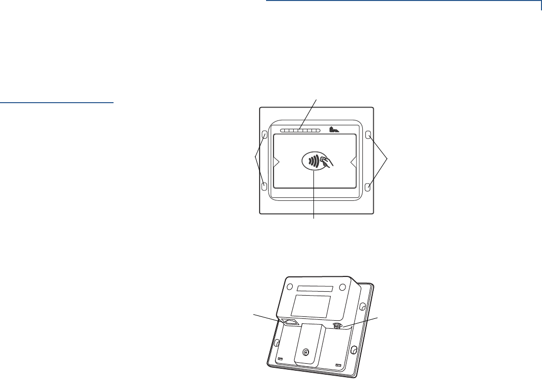
Figure 1 UX400 Front View
Figure 2 UX400 Rear View
Front Functions
The front of the contactless device shows the following:
•Customer-view indicator LEDs
•The CTLS logo
•Mounting stud holes
Back Functions
The rear of the contactless device shows the following connectors:
•RJ-45 host communication connector
•SMA (RF) antenna connector
VeriFone
LEDS
CTLS LOGO
MOUNTING
STUD HOLES
MOUNTING
STUD HOLES
RJ45 HOST
CONNECTOR SMA
CONNECTOR
SETUP
Connecting Unit to a Controlling Device
14 UX400 CTLS READER INSTALLATION GUIDE
Connecting Unit
to a Controlling
Device
The device’s rear panel has two ports for connection to the UX300 controlling
device:
•RJ45–8-pin host connector
•SMA connector
Both connections are necessary for using the contactless unit.
To connect to the
UX300 1Connect the RJ-45 plug to the rear of the contactless unit.
2Connect the 8-pin connector to the UX300 unit.
3Screw in the SMA connector to the rear of the contactless unit.
4Screw in the SMA connector the UX300 unit.
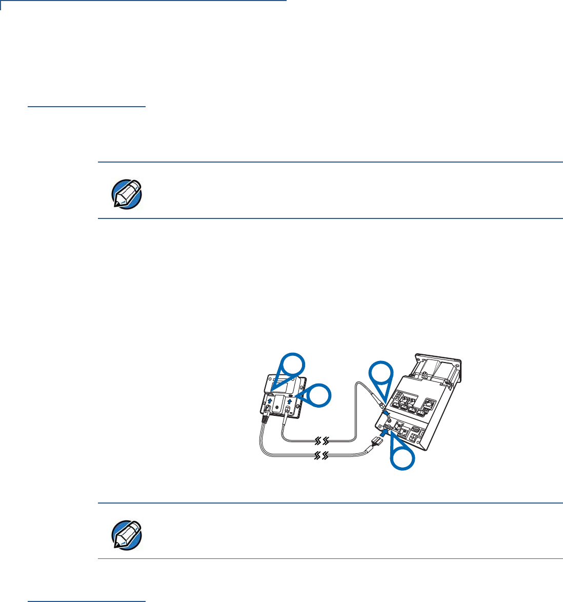
For further cabling instructions, see Figure 3
Figure 3 UX400 – UX300 Cabling Connections
Contactless
Support
This device supports the global contactless program specifications from American
Express, MasterCard, Visa, Discover, ISIS SmartTap, and Google Wallet with
virtually no changes to existing payment hardware or software.
NOTE
The cables used to connect to the UX300 unit are: CBL159-302-02-X for SMA
connection, and CBL159-301-01-X for data connection.
See Accessories and Documentation for cable ordering information.
RJ-45
SMA
SMA
UX300
8-Pin
NOTE
To disconnect cables, use the same steps described above in reverse. If
exchanging cables, use a VeriFone-approved cable. See Accessories and
Documentation for cable ordering information.
SETUP
Mounting the Reader
UX400 CTLS READER INSTALLATION GUIDE 15
Mounting the
Reader
The reader is designed to be flush-mounted to the mounting surface, without
further need for any external mounting devices.
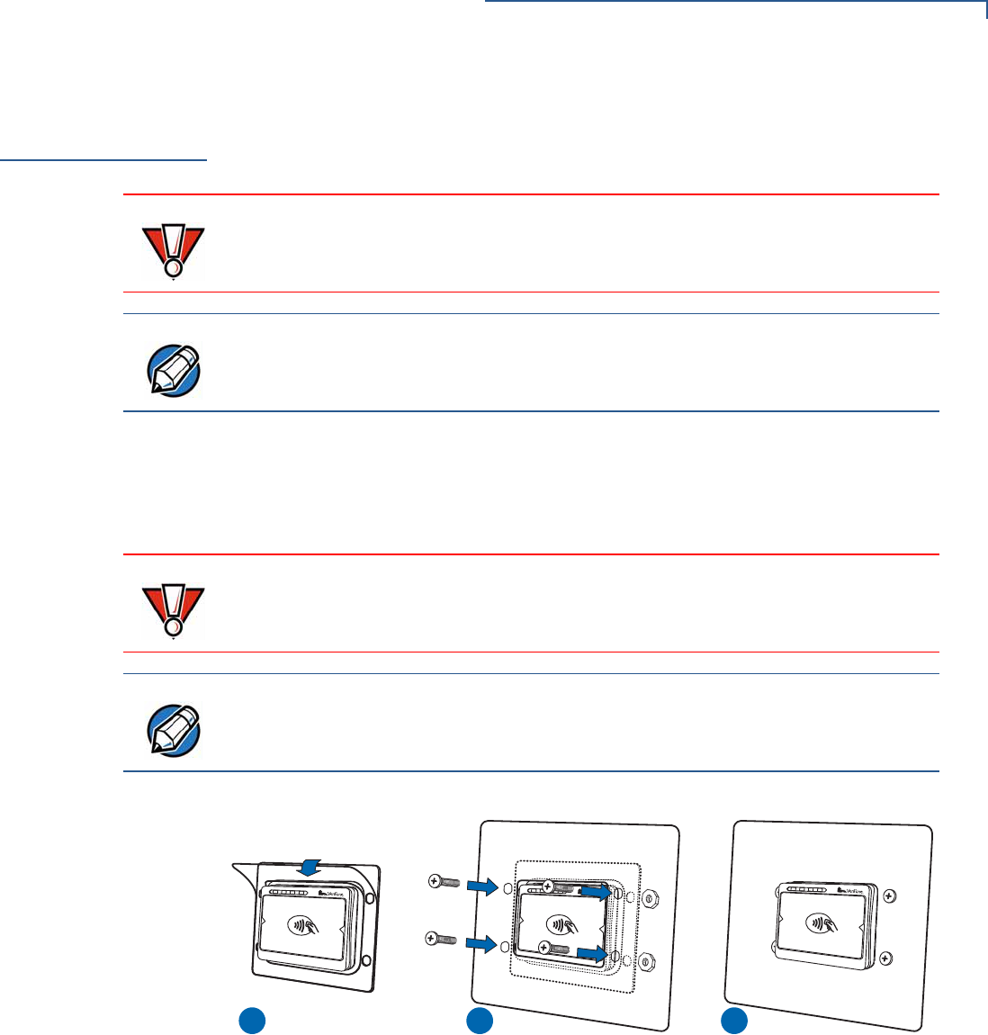
To mount the CTLS
device 1Peel off the plastic liner from the front of the unit.
2Align the unit’s stud holes with the stud holes of your mounting surface.
3Flush-mount the reader and secure the unit with M5 nuts.
Figure 4 Mounting the Reader
CAUTION
Ensure that your mounting frame has a thickness of 2 mm.
NOTE
Your mounting surface may have different installation instructions. Refer to your
mounting device’s user guide for further instructions.
CAUTION
Avoid placing metallic objects at the front of the card reader.
NOTE
Use M5 mounting studs with a minimum length of 12 mm.
Tighten the nuts using a recommended tightening torque of 7.0 kgfcm.
1 2 3
SETUP
Using the Reader
16 UX400 CTLS READER INSTALLATION GUIDE
Using the
Reader
The contactless reader is only active when signaled by an application for the
conduction of a contactless card transaction.
When active, the device’s contactless logo lights up.
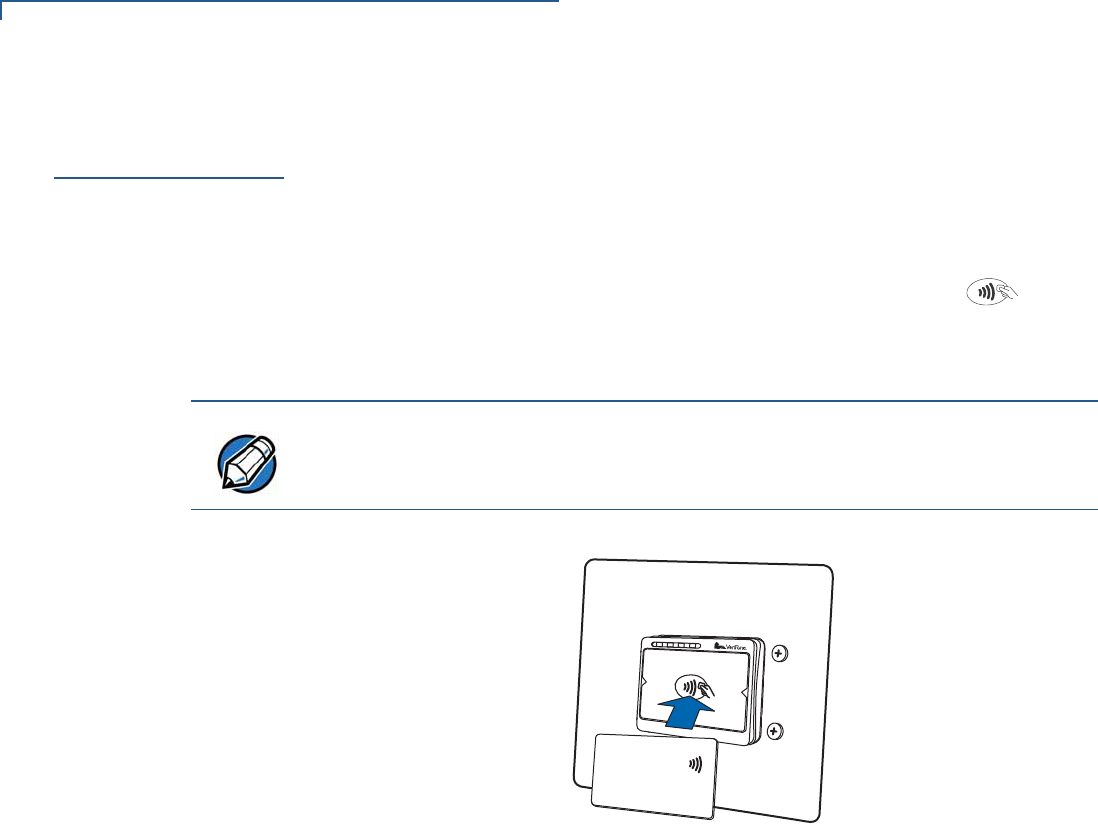
Conducting a
Contactless
Transaction
To conduct a contactless transaction, hold the card (within 4 cm) or gently tap
against the surface of the contactless antenna, marked by the logo .
The contactless unit uses various audible and visual confirmations to confirm
transactions.
Figure 5 Conducting a Contactless Transaction
NOTE
The actual audible and visual confirmations may vary depending on regional and
customer requirements.
UX400 CTLS READER INSTALLATION GUIDE 17
CHAPTER 3
Specifications
This chapter discusses power requirements, dimensions, and other specifications
of the contactless reader.
Power Consumption
•Power consumption mode: 450mW, maximum
•Sleep mode: 0.3W
Temperature
•Operating temperature: -20°C – 70°C (-4°F – 158°F)
•Storage temperature: -25°C – 70°C (-13°F – 158°F)
•Relative humidity: 5% to 90% RH non-condensing
External
Dimensions
•Length: 96 mm (3.78 in)
•Width: 99 mm (3.9 in)
•Depth: 46 mm (1.81 in)
Weight
•Unit weight: 142 gr (5 oz)
CTLS Card Reader
•4 LEDs for CTLS indications
Peripheral Ports
•RJ45 host communication port
•SMA (RF) antenna
Communication
•SPI:
•I2C:
NOTE
If this device is to be used in the Nordic countries, or in any environment where
the temperature range exceeds the product’s operating temperature, it is the
responsibility of the integrators to ensure that the ambient environment is
controlled in such a way to ensure that the product operates within the specified
temperature range.

SPECIFICATIONS
18 UX400 CTLS READER INSTALLATION GUIDE
UX400 CTLS READER INSTALLATION GUIDE 19
CHAPTER 4
Maintenance and Cleaning
Your contactless device is a product of superior design and craftsmanship and
should be treated with care. It has no user-serviceable parts.
The following suggestions will help you protect your warranty coverage.
•Do not store the device in hot areas. High temperatures can shorten the
life of electronic devices, damage batteries, and warp or melt certain
plastics.
•Do not store the device in cold areas. When the device returns to its
normal temperature, moisture can form inside the device and damage
electronic circuit boards.
•Do not drop, knock, or shake the device. Rough handling can break
internal circuit boards and fine mechanics.
•Do not use harsh chemicals, cleaning solvents, or strong detergents to
clean the device. Use only a soft, clean, dry cloth for cleaning.
These suggestions apply equally to your contactless device, or any of its
attachments or accessories. If your device is not working properly, take it to the
nearest VeriFone-authorized service provider for servicing or replacement.
Additional
Safety
Information
The following is additional information for your safety in using this device.
Potentially
Explosive
Environments
When using the device in areas with potential risk of explosion, such as petrol
stations, follow the advice of all signs and instructions. If there has been a leak, do
not use this device.
CAUTION
Never use thinner, trichloroethylene, or ketone-based solvents – they can
deteriorate plastic or rubber parts.

MAINTENANCE AND CLEANING
Additional Safety Information
20 UX400 CTLS READER INSTALLATION GUIDE
UX400 CTLS READER INSTALLATION GUIDE 21
CHAPTER 5
Service and Support
For UX400 problems, contact your local VeriFone representative or service
provider.
For device product service and repair information:
•USA – VeriFone Service and Support Group, 1-800-834-4366,
Monday - Friday, 8 A.M. - 8 P.M., eastern time.
•International – Contact your VeriFone representative.
Service Returns
Before returning the CTLS reader to VeriFone, you must obtain a Merchandise
Return Authorization (MRA) number. The following procedure describes how to
return one or more CTLS units for repair or replacement (U.S. customers only).
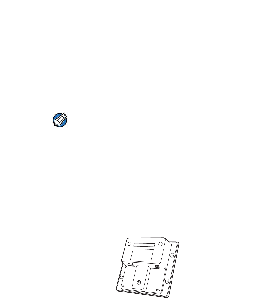
1Gather the following information from the printed labels (see Figure 6) on the
bottom of each unit to be returned:
•Product ID, including the model and part number. For example,
“M159-400-xx-WWB” and “PTID xxxxxxxx.”
•Serial number (S/N xxx-xxx-xxx).
2Within the United States, call VeriFone toll-free at 1-800-834-4366.
3Select the MRA option from the automated message. The MRA department is
open Monday–Friday, 8 A.M.–8 P.M., eastern time.
NOTE
International customers, please contact your local VeriFone representative for
assistance with your service, return, or replacement.
SERVICE AND SUPPORT
Service Returns
22 UX400 CTLS READER INSTALLATION GUIDE
4Give the MRA representative the information gathered in Step 1.
If the list of serial numbers is long, you can fax the list, along with the
information gathered in Step 1, to the MRA department at 1-727-953-4172
(U.S.).
•Please address the fax clearly to the attention of the “VeriFone MRA
Dept.”
•Include a telephone number where you can be reached and your fax
number.
•You will be issued MRA number(s) and the fax will be returned to you.
5Describe the problem(s) and provide the shipping address where the repaired
or replacement unit must be returned.
6Keep a record of the following items:
•Assigned MRA number(s).
•VeriFone serial number assigned to the unit you are returning for service
or repair (serial numbers are located on the bottom of the unit,
see Figure 6).
•Shipping documentation, such as air bill numbers used to trace the
shipment.
•Model(s) returned (model numbers are located on the VeriFone label on
the bottom of the unit).
Figure 6 Information Labels on Unit Bottom
NOTE
One MRA number must be issued for each unit you return to VeriFone, even if
you are returning several of the same model.
MODEL AND
SERIAL NUMBERS

SERVICE AND SUPPORT
Accessories and Documentation
UX400 CTLS READER INSTALLATION GUIDE 23
Accessories and
Documentation
VeriFone produces accessories and documentation for the contactless reader.
When ordering, please refer to the part number in the left column.
VeriFone Online Store at www.store.verifone.com
•USA – VeriFone Customer Development Center, 1-800-834-4366,
Monday - Friday, 7 A.M. - 8 P.M., eastern time
•International – Contact your VeriFone representative
Cables
The following cables can be used with the CTLS unit. Contact your local VeriFone
distributor to determine which cable fits your needs:
Various others, depending on what they connect to. Contact your local
VeriFone representative or service provider to identify the best cable for your
needs.
Cleaning Kit
Documentation
CBL159-301-01-X RJ-45–8-pin connector.
UX300–UX400 host communication cable.
CBL159-302-01-X SMA connector.
RF coaxial cable connector from the UX400 to
UX300.
02746 VeriFone Cleaning Kit
UX400 CTLS Reader Certifications and Regulations
Sheet
VPN - DOC159-031-EN-A
UX400 CTLS Reader Quick Installation Guide VPN - DOC159-032-EN-A
UX400 CTLS Reader Reference Guide VPN - DOC159-034-EN-A
UX300 Manual Card Reader Certifications and
Regulations Sheet
VPN - DOC159-021-EN-A
UX300 Manual Card Reader Quick Installation Guide VPN - DOC159-022-EN-A
UX300 Manual Card Reader Installation Guide VPN - DOC159-023-EN-A
UX300 Manual Card Reader Reference Guide VPN - DOC159-024-EN-A

SERVICE AND SUPPORT
Accessories and Documentation
24 UX400 CTLS READER INSTALLATION GUIDE
UX400 CTLS READER INSTALLATION GUIDE 25
CHAPTER 6
Troubleshooting
Guidelines
This chapter lists possible malfunctions that may occur while operating a UX400
device and the appropriate corrective action. If the problem persists - even after
performing the outlined guidelines, or if the problem is not described, contact your
local VeriFone representative for assistance.
Transactions
Fail to Process
If a contactless transaction fails to process:
•Perform a test transaction using one or more different contactless cards to
ensure the problem is not a defective card.
•Ensure that you are conducting the contactless transaction properly (see
Using the Reader).
•Ensure that all cables and external power connections are connected properly
to the contactless unit and all external devices (see Connecting Unit to a
Controlling Device).
•If the problem persists, contact your local VeriFone representative.
NOTE
The unit comes equipped with tamper-evident labels. The reader contains no
user-serviceable parts. Do not, under any circumstance, attempt to disassemble
the unit. Perform only those adjustments or repairs specified in this guide. For all
other services, contact your local VeriFone service provider. Service conducted
by parties other than authorized VeriFone representatives may void any warranty.
CAUTION
Not all units require use of a power supply.
Using an incorrectly rated power supply may damage the unit or cause it not to
work properly. Before troubleshooting, ensure that the power supply used to
power the unit matches the requirements specified on the back of the unit (see
Specifications for detailed power supply specifications). If not, obtain the
appropriately rated power supply before continuing with troubleshooting.


*DOC159-031-EN-A*
c 2013 VeriFone, Inc. All rights reserved.
2099 Gateway Place, Suite 600
San Jose CA 95110
Tel: 800 VeriFone (837-4366)
www.verifone.com
UX400 CTLS Reader Certifications and Regulations
VeriFone Part Number: DOC159-031-EN-A Revision A
Electrical
The reference input power rating for the UX400 CTLS Reader is 450mW max.
Location – Electrical Considerations
Do not install this device near electrical appliances or other devices that cause excessive voltage fluctuations or emit electrical
noise (for example: air conditioners, neon signs, electric motors, high-frequency or magnetic security devices).
WARNING! This device contains sensitive electronic components that can be permanently damaged if exposed to excessive
shock, electrical interference or vibration.
Equipment
Repairs
Do not, under any circumstances, attempt any service, adjustments, or repairs on this equipment. Instead, contact your local
VeriFone distributor or service provider for assistance. Failure to comply may void the product warranty.
Damage
Carefully inspect the shipping carton and its contents for any damage. If the UX400 CTLS Reader or any product component
appears damaged or tampered, immediately notify the shipping company and your VeriFone distributor or service provider.
Do not use a device that has been damaged or tampered with.
Cleaners and Solvents
Never use thinner, trichloroethylene, or ketone-based solvents to clean the device — they may deteriorate the plastic and rubber
parts. For best results, use a clean cloth dampened with water and mild soap. To remove stubborn stains, use alcohol or an alcohol-
based cleaner.
UX400 CTLS Reader Certifications and Regulations
FCC Compliance
The following product has been tested and certified as compliant with the regulations and guidelines set forth in Part 15 of FCC
Rules:
Manufacturer: VeriFone, Inc.
Brand, Model: UX400 CTLS Reader
Part 15 of FCC Rules
This device complies with the limits for a Class B digital device as specified in Part 15 of FCC Rules which provide reasonable
protection against harmful interference in a residential area.
This device complies with Part 15 of the FCC Rules.
Operation is subject to the following two conditions:
1This device may not cause harmful interference; and,
2This device must accept any interference received, including interference that may cause undesired operation.
This equipment generates and uses radio frequency energy, and if not installed and used in accordance with the instructions, may
cause harmful interference to radio communications. However, there is no guarantee that interference will not occur in a particular
installation.
In the unlikely event that there is interference to radio or television reception (which can be determined by turning the equipment off
and on), the user is encouraged to try to correct the interference by one or more of the following measures:
• Increase the separation between the equipment and receiver.
• Connect the equipment into an outlet on a circuit different from that to which the receiver is connected.
• Consult with the dealer or ask an experienced radio/TV technician for help.
Any changes or modifications to this equipment not expressly approved by VeriFone could void the user’s authority to operate this
equipment. The antenna(s) used for this transmitter must not be co-located or operating in conjunction with any other antenna or
transmitter. Use of a shielded interface cable is required to comply with the Class B limits of Part 15 of FCC Rules.
RF Exposure
This device was verified for RF exposure. To comply with Council Recommendation 1999/519/EC, IC RSS-102, and FCC RF
exposure requirements, a minimum separation distance of 20 cm must be maintained between the user's body and the device,
including the antenna. Any metallic components should be far from this device. Conditions that do not meet these requirements
may not comply with Council Recommendation 1999/519/EC, IC RSS-102 and FCC RF exposure requirements and should be
avoided.
To comply with the FCC RF exposure compliance requirements, make sure to use only the antenna that is included with the device.
This device and its antenna must not be in the same location or operating in the same area in conjunction with any other antenna or
transmitter.
Legal Terms and Conditions Regarding PCI SSC Approvals
PCI SSC’s approval only applies to PEDs that are identical to the PED tested by a PCI Security Standards Council recognized
laboratory. If any aspect of the PED is different from that which was tested by the laboratory - even if the PED conforms to the basic
product description contained in the letter, then the PED model should not be considered approved, nor promoted as approved. For
example, if a PED contains firmware, software, or physical construction that has the same name or model number as those tested
by the laboratory, but in fact are not identical to those PED samples tested by the laboratory, then the PED should not be
considered or promoted as approved.
No vendor or other third party may refer to a PED as “PCI Approved,” nor otherwise state or imply that PCI SSC has, in whole or
part, approved any aspect of a vendor or its PEDs, except to the extent and subject to the terms and restrictions expressly set forth
in a written agreement with PCI SSC, or in an approval letter. All other references to PCI SSC’s approval are strictly and actively
prohibited by PCI SSC.
When granted, an approval is provided by PCI SSC to ensure certain security and operational characteristics important to the
achievement of PCI SSC’s goals, but the approval does not under any circumstances include any endorsement or warranty
regarding the functionality, quality, or performance of any particular product or service. PCI SSC does not warrant any products or
services provided by third parties. Approval does not, under any circumstances, include or imply any product warranties from PCI
SSC, including, without limitation, any implied warranties of merchantability, fitness for purpose or noninfringement, all of which are
expressly disclaimed by PCI SSC. All rights and remedies regarding products and services, which have received an approval, shall
be provided by the party providing such products or services, and not by PCI SSC or the payment brand participants.
This equipment operates on a secondary basis. It is not entitled to protection from harmful interference, even for stations of the
same type, and may not cause interference to systems operating on a primary basis.
Recycling: DO NOT DISCARD!
UNIT MUST BE RECYCLED OR DISPOSED OF PROPERLY
For proper disposal instructions go to http://recycle.verifone.com/Please retain this sheet for future reference.
continued on rear cover