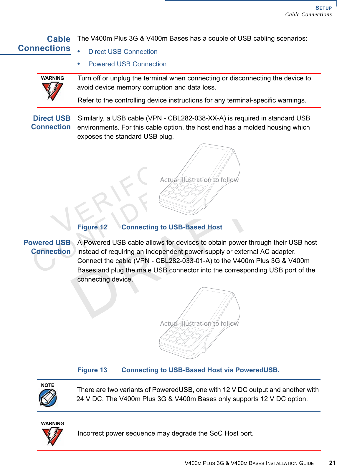
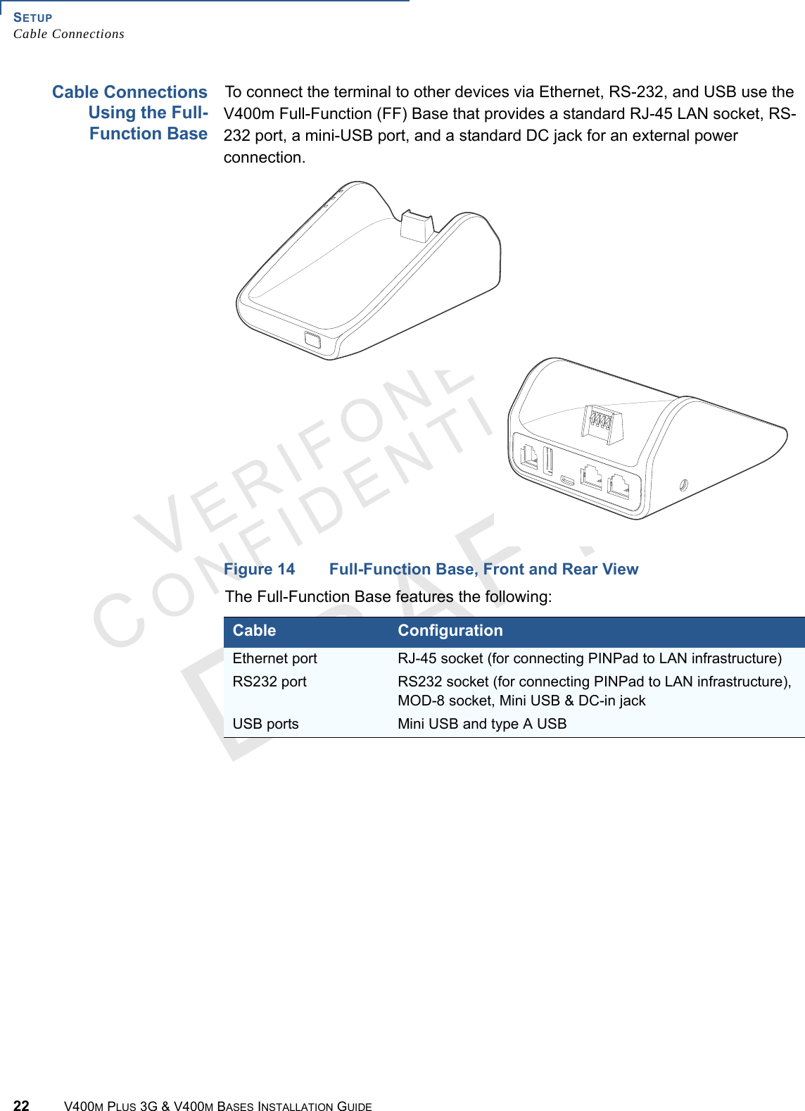
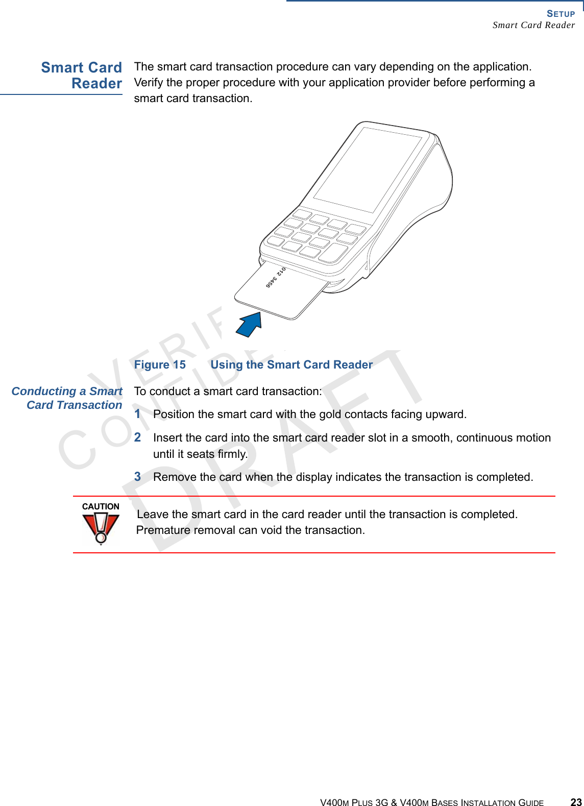
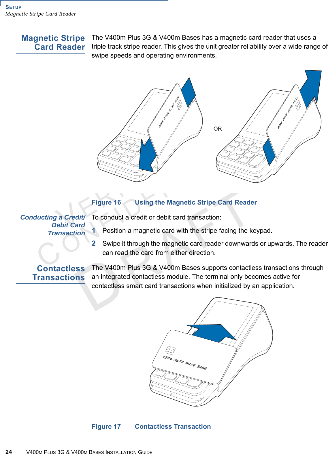
Verifone V400MBFF Charging Base User Manual

VeriFone Inc Charging Base

User Manual

Verifone Part Number DOC475-003-EN-A, Revision A.1VERI F O N ECONF I DENTIALV400m Plus 3G & V400m BasesInstallation Guide
All  rights  reserved.  No  part  of  the  contents  of  this  document  may  be  reproduced  or  transmitted  in  any  form  without  the  writtenpermission of Verifone, Inc.The  information  contained  in  this  document  is  subject  to  change  without  notice.  Although  Verifone  has  attempted  to  ensure  theaccuracy of the contents of this document, this document may include errors or omissions. The examples and sample programs arefor illustration only and may not be suited for your purpose. You should verify the applicability of any example or sample programbefore placing the software into productive use. This document, including without limitation the examples and software programs, issupplied “As-Is.”Verifone Inc.1-800-Verifonewww.verifone.comVerifone Part Number DOC475-003-EN-A, Revision A.1V400m Plus 3G & V400m Bases Installation Guide© 2016 Verifone, Inc.Verifone and the Verifone logo are registered trademarks of Verifone. Other brand names or trademarks associated with Verifone’sproducts and services are trademarks of Verifone, Inc. All other brand names and trademarks appearing in this manual are the property of their respective holders. Product WarrantyFor product warranty information, visit http://www.verifone.com/terms.Comments? Please e-mail all comments on this document to your local Verifone Support Team.
V400M PLUS 3G & V400M BASES INSTALLATION GUIDE 3VERI F O N ECONF I DENTIALREVISION A.1 CONTENTSPREFACE  . . . . . . . . . . . . . . . . . . . . . . . . . . . . . . . . . . . . . . .  5Audience. . . . . . . . . . . . . . . . . . . . . . . . . . . . . . . . . . . . . . . . . . . . . . . . . . . . . . . . 5Organization . . . . . . . . . . . . . . . . . . . . . . . . . . . . . . . . . . . . . . . . . . . . . . . . . . . . . 5Related Documentation  . . . . . . . . . . . . . . . . . . . . . . . . . . . . . . . . . . . . . . . . . . . . 5Guide Conventions. . . . . . . . . . . . . . . . . . . . . . . . . . . . . . . . . . . . . . . . . . . . . . . . 6Acronym Definitions  . . . . . . . . . . . . . . . . . . . . . . . . . . . . . . . . . . . . . . . . . . . . 6CHAPTER 1Overview V400m Plus 3G  . . . . . . . . . . . . . . . . . . . . . . . . . . . . . . . . . . . . . . . . . . . . . . . . . . 9Front Functions . . . . . . . . . . . . . . . . . . . . . . . . . . . . . . . . . . . . . . . . . . . . . . . . 9Back Functions . . . . . . . . . . . . . . . . . . . . . . . . . . . . . . . . . . . . . . . . . . . . . . . 10V400m Bases . . . . . . . . . . . . . . . . . . . . . . . . . . . . . . . . . . . . . . . . . . . . . . . . . . . 10V400m Charging Base . . . . . . . . . . . . . . . . . . . . . . . . . . . . . . . . . . . . . . . . . 11V400m Full-Function Base . . . . . . . . . . . . . . . . . . . . . . . . . . . . . . . . . . . . . . 11Features and Benefits  . . . . . . . . . . . . . . . . . . . . . . . . . . . . . . . . . . . . . . . . . . . . 11Exceptional Ease of Use and Ergonomics . . . . . . . . . . . . . . . . . . . . . . . . . . 12Critical Security Protection . . . . . . . . . . . . . . . . . . . . . . . . . . . . . . . . . . . . . . 12CHAPTER 2Setup Selecting Location  . . . . . . . . . . . . . . . . . . . . . . . . . . . . . . . . . . . . . . . . . . . . . . . 13Environmental Factors  . . . . . . . . . . . . . . . . . . . . . . . . . . . . . . . . . . . . . . . . . 13Electrical Considerations  . . . . . . . . . . . . . . . . . . . . . . . . . . . . . . . . . . . . . . . 14Contactless Considerations  . . . . . . . . . . . . . . . . . . . . . . . . . . . . . . . . . . . . . 14PIN Protection Measures . . . . . . . . . . . . . . . . . . . . . . . . . . . . . . . . . . . . . . . . . . 14Ensuring User Privacy  . . . . . . . . . . . . . . . . . . . . . . . . . . . . . . . . . . . . . . . . . 15Unpacking Shipping Carton . . . . . . . . . . . . . . . . . . . . . . . . . . . . . . . . . . . . . . . . 15MSAM, Micro SD and SIM Cards . . . . . . . . . . . . . . . . . . . . . . . . . . . . . . . . . . . . 16Accessing Card Compartments  . . . . . . . . . . . . . . . . . . . . . . . . . . . . . . . . . . 16Changing or Installing MSAMs . . . . . . . . . . . . . . . . . . . . . . . . . . . . . . . . . . . 16Changing or Installing a Micro SD Card . . . . . . . . . . . . . . . . . . . . . . . . . . . . 17Changing or Installing a SIM Card  . . . . . . . . . . . . . . . . . . . . . . . . . . . . . . . . 18Loading Printer Paper. . . . . . . . . . . . . . . . . . . . . . . . . . . . . . . . . . . . . . . . . . . . . 19Power Supply . . . . . . . . . . . . . . . . . . . . . . . . . . . . . . . . . . . . . . . . . . . . . . . . . . . 19USB Power Supply . . . . . . . . . . . . . . . . . . . . . . . . . . . . . . . . . . . . . . . . . . . . 20Cable Connections . . . . . . . . . . . . . . . . . . . . . . . . . . . . . . . . . . . . . . . . . . . . . . . 21Direct USB Connection . . . . . . . . . . . . . . . . . . . . . . . . . . . . . . . . . . . . . . . . . 21Powered USB Connection  . . . . . . . . . . . . . . . . . . . . . . . . . . . . . . . . . . . . . . 21Cable Connections Using the Full-Function Base  . . . . . . . . . . . . . . . . . . . . 22Smart Card Reader  . . . . . . . . . . . . . . . . . . . . . . . . . . . . . . . . . . . . . . . . . . . . . . 23Magnetic Stripe Card Reader. . . . . . . . . . . . . . . . . . . . . . . . . . . . . . . . . . . . . . . 24Contactless Transactions . . . . . . . . . . . . . . . . . . . . . . . . . . . . . . . . . . . . . . . . . . 24Optional Accessories . . . . . . . . . . . . . . . . . . . . . . . . . . . . . . . . . . . . . . . . . . . . . 25Full-Function Base  . . . . . . . . . . . . . . . . . . . . . . . . . . . . . . . . . . . . . . . . . . . . 25Charging Base  . . . . . . . . . . . . . . . . . . . . . . . . . . . . . . . . . . . . . . . . . . . . . . . 25Periodic Inspection . . . . . . . . . . . . . . . . . . . . . . . . . . . . . . . . . . . . . . . . . . . . . . . 26
4V400M PLUS 3G & V400M BASES INSTALLATION GUIDEVERI F O N ECONF I DENTIALREVISION A.1 CHAPTER 3Specifications V400m Plus 3G Terminal . . . . . . . . . . . . . . . . . . . . . . . . . . . . . . . . . . . . . . . . . . 27Unit Power Requirements . . . . . . . . . . . . . . . . . . . . . . . . . . . . . . . . . . . . . . . 27Temperature . . . . . . . . . . . . . . . . . . . . . . . . . . . . . . . . . . . . . . . . . . . . . . . . . 27Humidity  . . . . . . . . . . . . . . . . . . . . . . . . . . . . . . . . . . . . . . . . . . . . . . . . . . . . 27External Dimensions . . . . . . . . . . . . . . . . . . . . . . . . . . . . . . . . . . . . . . . . . . . 27Weight. . . . . . . . . . . . . . . . . . . . . . . . . . . . . . . . . . . . . . . . . . . . . . . . . . . . . . 27Processor . . . . . . . . . . . . . . . . . . . . . . . . . . . . . . . . . . . . . . . . . . . . . . . . . . . 27Memory . . . . . . . . . . . . . . . . . . . . . . . . . . . . . . . . . . . . . . . . . . . . . . . . . . . . . 27SD Memory . . . . . . . . . . . . . . . . . . . . . . . . . . . . . . . . . . . . . . . . . . . . . . . . . . 27Display  . . . . . . . . . . . . . . . . . . . . . . . . . . . . . . . . . . . . . . . . . . . . . . . . . . . . . 28SAM Card Reader. . . . . . . . . . . . . . . . . . . . . . . . . . . . . . . . . . . . . . . . . . . . . 28CTLS Reader  . . . . . . . . . . . . . . . . . . . . . . . . . . . . . . . . . . . . . . . . . . . . . . . . 28Magnetic Card Reader . . . . . . . . . . . . . . . . . . . . . . . . . . . . . . . . . . . . . . . . . 28Primary Smart Card  . . . . . . . . . . . . . . . . . . . . . . . . . . . . . . . . . . . . . . . . . . . 28Speaker. . . . . . . . . . . . . . . . . . . . . . . . . . . . . . . . . . . . . . . . . . . . . . . . . . . . . 28Communication . . . . . . . . . . . . . . . . . . . . . . . . . . . . . . . . . . . . . . . . . . . . . . . 28Battery Pack . . . . . . . . . . . . . . . . . . . . . . . . . . . . . . . . . . . . . . . . . . . . . . . . . 28Power Pack. . . . . . . . . . . . . . . . . . . . . . . . . . . . . . . . . . . . . . . . . . . . . . . . . . 29Integrated Printer  . . . . . . . . . . . . . . . . . . . . . . . . . . . . . . . . . . . . . . . . . . . . . 29Security . . . . . . . . . . . . . . . . . . . . . . . . . . . . . . . . . . . . . . . . . . . . . . . . . . . . . 29V400m Bases . . . . . . . . . . . . . . . . . . . . . . . . . . . . . . . . . . . . . . . . . . . . . . . . . . . 29Unit Power Requirements . . . . . . . . . . . . . . . . . . . . . . . . . . . . . . . . . . . . . . . 29External Dimensions . . . . . . . . . . . . . . . . . . . . . . . . . . . . . . . . . . . . . . . . . . . 29Weight. . . . . . . . . . . . . . . . . . . . . . . . . . . . . . . . . . . . . . . . . . . . . . . . . . . . . . 29Security . . . . . . . . . . . . . . . . . . . . . . . . . . . . . . . . . . . . . . . . . . . . . . . . . . . . . 30CHAPTER 4TroubleshootingGuidelinesDisplay Panel Does Not Work  . . . . . . . . . . . . . . . . . . . . . . . . . . . . . . . . . . . . . . 31Keypad Does Not Respond  . . . . . . . . . . . . . . . . . . . . . . . . . . . . . . . . . . . . . . . . 31Transactions Fail To Process . . . . . . . . . . . . . . . . . . . . . . . . . . . . . . . . . . . . . . . 31CHAPTER 5Service and Support Maintenance and Cleaning. . . . . . . . . . . . . . . . . . . . . . . . . . . . . . . . . . . . . . . . . 33Service Returns  . . . . . . . . . . . . . . . . . . . . . . . . . . . . . . . . . . . . . . . . . . . . . . . . . 33Accessories and Documentation . . . . . . . . . . . . . . . . . . . . . . . . . . . . . . . . . . . . 35Cables. . . . . . . . . . . . . . . . . . . . . . . . . . . . . . . . . . . . . . . . . . . . . . . . . . . . . . 35Base . . . . . . . . . . . . . . . . . . . . . . . . . . . . . . . . . . . . . . . . . . . . . . . . . . . . . . . 35Power Supply . . . . . . . . . . . . . . . . . . . . . . . . . . . . . . . . . . . . . . . . . . . . . . . . 36Cleaning Kit. . . . . . . . . . . . . . . . . . . . . . . . . . . . . . . . . . . . . . . . . . . . . . . . . . 36Documentation . . . . . . . . . . . . . . . . . . . . . . . . . . . . . . . . . . . . . . . . . . . . . . . 36Caution and Warning Messages  . . . . . . . . . . . . . . . . . . . . . . . . . . . . . . . . . . . . 37
VERI F ONECONF I DENTIAL V400M PLUS 3G & V400M BASES INSTALLATION GUIDE 5PREFACEThis guide is the primary source of information for setting up and installing the V400m Plus 3G and V400m Bases. The installation should be performed by professional staffs from Verifone.Audience This  guide  provides simple descriptions of the product features and information for installing and configuring the V400m Plus 3G terminal and the V400m Charg-ing and Full-Function Bases.Organization This  guide  is  organized  as  follows:Chapter 1, Overview. Provides an overview of a V400m Plus 3G & V400m Bases.Chapter 2, Setup. Explains how to set up and install the V400m Plus 3G & V400m Bases and establish connections with other devices.Chapter 3, Specifications. Discusses the power requirements and dimensions of the V400m Plus 3G & V400m Bases.Chapter 4, Troubleshooting Guidelines. Provides troubleshooting tips.Chapter 5, Service and Support. Provides information on contacting your Verifone service provider, ordering accessories or documentation from Verifone, and maintaining the V400m Plus 3G & V400m Bases.Appendix A, Caution and Warning Messages. Shows the UL/cUL certification-compliant translations of all Warning and Caution messages in this installation guide.RelatedDocumentationTo learn more about the V400m Plus 3G and V400m Bases, please refer to the following documents and their associated Verifone Part Numbers (VPN):V400m Plus 3G Certifications and Regulations VPN DOC475-001-ENV400m Plus 3G Quick Installation Guide VPN DOC475-002-ENV400m Plus 3G Reference Guide VPN DOC475-004-ENV400m B-Charging Quick Installation Guide VPN DOC475-006-ENV400m B-FF Quick Installation Guide VPN DOC475-007-ENV400m B-Charging Certifications & Regulations Sheet VPN DOC475-011-ENV400m B-FF Certifications & Regulations Sheet VPN DOC475-021-EN
PREFACEGuide Conventions6V400M PLUS 3G & V400M BASES INSTALLATION GUIDEVERI F O N ECONF I DENTIAL GuideConventionsPlease refer to the following document conventions for quickly identifying special formatting.Table 1 describes these conventions and provides examples of their use.Acronym DefinitionsPlease refer to Table 2 for the acronyms used in this manual. Table 1 Document ConventionsConvention Meaning ExampleBlue Text in blue indicates terms that are cross-references.See Guide Conventions.Italics Italic typeface indicates book titles or emphasis.You must not use this unit underwater.The pencil icon is used to highlight important information.RS-232-type devices do not work on the V400m Plus 3G & V400m Bases communication port.The caution symbol indicates hardware or software failure, or loss of data.The unit is not waterproof or dustproof, and is intended for indoor use only.The lightning symbol is used as a warning when bodily injury might occur.Due to risk of shock do not use the unit near water.NOTECAUTIONWARNINGTable 2 Acronym DefinitionsAcronym Definitions3DES Triple Data Encryption AlgorithmAC Alternating CurrentANSI American National Standards InstitutecUL Underwriters' Laboratories of CanadaDC Direct CurrentDUKPT Derived Unique Key Per Transaction Method as defined in the VISA’s POS Equipment Requirement: PIN processing and Data Authentication, International Version 1.0, August 1988ECR Electronic Cash RegisterEMV Europay, MasterCard, and VisaISO International Organization for StandardizationMRA Merchandise Return AuthorizationMSAM Multiple Secure Access ModuleLAN Local Area NetworkLCD Liquid Crystal DisplayLED Light-Emitting DiodePED PIN Entry Device
PREFACEGuide ConventionsV400M PLUS 3G & V400M BASES INSTALLATION GUIDE 7VERI F O N ECONF I DENTIAL PIN Personal Identification NumberPOS Point-of-SaleRS-232 Recommend Standard number 232SAM Secure Access ModuleSD Secure DigitalUL Underwriters LaboratoriesUSB Universal Serial BusVPN Verifone Part NumberTable 2 Acronym Definitions  (continued)Acronym Definitions
PREFACEGuide Conventions8V400M PLUS 3G & V400M BASES INSTALLATION GUIDEVERI F O N ECONF I DENTIAL
VERI F O N ECONF I DENTIAL V400M PLUS 3G & V400M BASES INSTALLATION GUIDE 9CHAPTER 1OverviewThis chapter describes the features of the V400m Plus 3G and the V400m Bases.V400m Plus 3G The V400m Plus 3G is Verifone’s next generation integrated retail PINpad device. Its touchscreen functionality and sophisticated design is perfect for high-end retail establishments.The V400m Plus 3G is a consumer-facing handheld device. It can also be fix-mounted in some integrated retail scenarios. The product’s design is equally appealing as a handheld PINpad and robust enough to look and function appropriately in a fixed mount setting.Figure 1 V400m Plus 3G FrontFront Functions The V400m Plus 3G includes the following features:•Capacitive touch LCD display and CTLS tap area•Smart card reader•Magnetic card reader•Integrated thermal printer•Secure keypad supporting 3x5 matrix containing 0-9, *, #, Cancel, Backspace/Clear, and Enter keys.•Dual-function Backspace/Clear key.•Customer-entry for Cancel and Enter keys.TOUCHSCREEN DISPLAYAND CTLS AREASECURE KEYPADSMART CARDREADERCANCEL KEYMAGNETICSTRIPREADERBACKSPACE KEYENTER KEYTHERMAL PRINTER
OVERVIEWV400m Bases10 V400M PLUS 3G & V400M BASES INSTALLATION GUIDEVERI F O N ECONF I DENTIAL Back Functions After removing the rear cover and battery, the underside of the V400m Plus 3G shows the following:Figure 2 V400m Plus 3G Underside•A Micro SD slot •Dual MSAM slots to support stored-value card programs or other merchant card requirements•Dual SIM Card compartmentsV400m Bases The V400m Base provides a stable mounted platform for the V400m Plus 3G terminal. The Base comes in two versions:•V400m B Charging•V400m B Full-Function (FF)The Charging Base supports charging only with no communication functionality. The FF Base supports several connectivity options and provides serial connection for peripherals (like ECR, check reader, barcode reader, etc.). The USB host port is for maintenance purposes and supports a USB flash drive.12MICRO SD SLOTMSAMSLOTS SIM SLOTSPOWER PORTUSB PORTSPEAKERCHARGINGSTANDPORT
OVERVIEWFeatures and BenefitsV400M PLUS 3G & V400M BASES INSTALLATION GUIDE 11VERI F O N ECONF I DENTIAL V400m ChargingBaseThe Charging Base accomodates and supplies power to the V400m Plus 3G portable terminal.Figure 3 V400m Charging Base, Front and RearV400m Full-Function BaseThe FF Base supports any failover communication via dial up and Ethernet connections. The failover will be supported in all network interfaces available in a terminal.Figure 4 V400m FF Base, Front and RearThe FF Base supports a minimum of seven simultaneous terminal connections via Bluetooth (BT) as well as the following:•10/100M Ethernet•56K modem•USB host•USB deviceFeatures andBenefitsThe V400m Plus 3G terminal and V400m Bases provide the following functionality:TERMINAL CHARGING POINTSEXTERNAL POWER PORTTERMINAL CHARGING POINTSEXTERNAL ON/OFF POWERBUTTONPOWER PORTTELEPHONE PORTUSB HOST PORTUSB DEVICE PORTRS232 PORT ETHERNETPORT
OVERVIEWFeatures and Benefits12 V400M PLUS 3G & V400M BASES INSTALLATION GUIDEVERI F O N ECONF I DENTIAL Exceptional Ease ofUse andErgonomics•Touch screen enables easy menu control and signature capture.•Battery-powered for mobility and portable operation.•Integrated thermal printer for fast transaction processing.•Large, hard-rubber keys provide improved tactile feedback.•3.5” capacitive touch screen display.•3G-, WiFi-, and Bluetooth-capabale.•Intuitive keypad interface simplify training and reduce support requests.•Connects with most POS payment terminals, PCs, and ECRs.•Supports payment transactions in a variety of payment environments.•Rugged and reliable design absorbs hard knocks found at point-of-sale counters.•Sleek and stylish shape occupies minimal counter space.•Bold, ergonomic design fits comfortably in the palm of a hand.•Optional Charging or Full-Function Bases expand functionality while providing a stable, battery-charging platform.Critical SecurityProtection•Offers a choice of Master/Session or DUKPT key-management methods to protect PIN-based transactions.•Offers secure, reliable PIN input for expanding range of PIN-based transactions.•PCI 4.x-compliant for secure solutions, meeting the PED standard.•Meets ISO and ANSI standards for PIN encryption, key management, and MAC.•Key injection simplified and secured with Verifone’s SecureKit key loading software.
VERI F O N ECONF I DENTIAL V400M PLUS 3G & V400M BASES INSTALLATION GUIDE 13CHAPTER 2SetupThis chapter describes the setup procedure for the V400m Plus 3G & V400m Bases, in the following sections:•Selecting Location•PIN Protection Measures•Unpacking Shipping Carton•MSAM, Micro SD and SIM Cards•Loading Printer Paper•Power Supply•Cable Connections•Smart Card Reader•Magnetic Stripe Card Reader•Contactless Transactions•Optional Accessories•Periodic InspectionSelectingLocationUse the following guidelines to select the best location for the V400m Plus 3G & V400m Bases device.To Select a LocationChoose a location convenient for both merchant and client:•Far from heavy metal objects,•A flat support surface such as a countertop or a table,•Near a power outlet and the terminal or computer that connects to the V400m Plus 3G & V400m Bases.EnvironmentalFactors•Do not use the unit where there is high heat, dust, humidity, moisture, or caustic chemicals or oils.•Keep the unit away from direct sunlight and anything that radiates heat, such as a stove or a motor.WARNING For safety, do not string cables or cords across a walkway.
SETUPPIN Protection Measures14 V400M PLUS 3G & V400M BASES INSTALLATION GUIDEVERI F O N ECONF I DENTIAL •Do not use the V400m Plus 3G & V400m Bases outdoors.  ElectricalConsiderations•Avoid using this product during electrical storms.•Do not use the V400m Plus 3G & V400m Bases unit near water or in moist conditions.•Disconnect the device from its POS terminal before cleaning.ContactlessConsiderationsAvoid having metallic objects in proximity of the contactless antenna. If you need to mount the terminal to vertical or inclined surfaces, use a flat, non-metallic mounting plate.PIN ProtectionMeasuresUse the following techniques to provide effective screening of PIN-entry devices (PEDs) during the PIN entry process. You can use these methods in combination, although in some cases a single method might suffice.•Position the terminal on the check-in stand in such a way as to block visual observation of the PIN-entry process. Examples include:•Visual shields designed into the check-in stand. The shields may be solely for shielding purposes, or may be part of the general check stand design.•Position the PED so that it is angled in such a way that PIN spying is difficult.•Install the PED on an adjustable stand that allows consumers to swivel the terminal sideways and/or tilt it forwards/backwards to a position that makes visual observation of the PIN-entry process difficult.•Position in-store security cameras so that the PIN-entry keypad is not visible.CAUTIONThe V400m Plus 3G & V400m Bases is not waterproof or dustproof and is intended for indoor use only. Any damage to the unit from exposure to rain or dust can void any warranty.WARNINGDue to risk of electrical shock or terminal damage, do not use the terminal near water, including a bathtub, wash bowl, kitchen sink or laundry tub, in a wet basement, or near a swimming pool. Also, avoid using this product during electrical storms. Avoid locations near electrical appliances or other devices that cause excessive voltage fluctuations or emit electrical noise (for example, air conditioners, neon signs, high frequency or magnetic security devices, or electric motors).CAUTIONUsing an enclosed metal frame or mount may negatively affect contactless performance
SETUPUnpacking Shipping CartonV400M PLUS 3G & V400M BASES INSTALLATION GUIDE 15VERI F O N ECONF I DENTIAL The following table describes the two preferred mounting methods and the recommended measures to protect from PIN capture in four observation corridors:Verifone also recommends instruction of the cardholder regarding safe PIN-entry. This can be done with a combination of:•Signage on the PED•Prompts on the display, possibly with a click-through screen•Literature at the point of sale•A logo for safe PIN-entry process.Ensuring UserPrivacyTo protect users’ privacy when they enter their personal identification number (PIN), the area of visibility should be no larger than a cone taken from the number 5 key at an angle of 45° and covering an area of 270° directly in front of the user.UnpackingShipping CartonCarefully inspect the shipping carton and its contents for possible tampering or damage. 1Remove the V400m Plus 3G & V400m Bases unit from the shipping carton. The standard package contains the PIN pad, power pack, battery, and printer paper roll. Refer Accessories and Documentation to for more information about V400m Plus 3G & V400m Bases related accessories. 2Remove any protective plastic wrap and place the unit on a table or countertop.3Remove the clear protective film from the display.Table 3 Mounting Methods and Protection MeasuresMethod Cashier Customer in QueueCustomers ElsewhereOn-site CamerasCountertop without standUse signage behind the PEDInstall so that customer is between PED and next in queueNo action neededDo not install within view of camerasCountertop with standNo action neededInstall so that customer is between PED and next in queueNo action neededDo not install within view of camerasCAUTIONThis device is a secure product and any tampering can cause it to cease to function or operate in an unsecured manner.
SETUPMSAM, Micro SD and SIM Cards16 V400M PLUS 3G & V400M BASES INSTALLATION GUIDEVERI F O N ECONF I DENTIAL 4Replace all the packing materials, close the lid, and save the carton for repacking or moving the V400m Plus 3G & V400m Bases unit in the future.  MSAM, Micro SDand SIM CardsYou may need to install or replace the multiple security access module (MSAM), Micro Secure Digital (SD) and Subscriber Identity Module (SIM) cards.Accessing CardCompartmentsUse the following procedure in order to access the cardholder compartment.1Place the terminal face down on a soft and clean surface to protect the lens from scratches.2Slide to unlock and lift the compartment cover. 3Remove the battery to access the MSAM cardholders.Figure 5 How to Access CardholdersChanging orInstalling MSAMsTo change or install MSAM cards:1Use steps 1 to 3 of Accessing Card Compartments to get to the MSAM cardholder.2Unlock the cardholder and turn upwards to allow the insertion or removal of cards.WARNINGDo not use a unit that has been tampered with or otherwise damaged. This unit comes equipped with tamper-evident label. If a label or component appears damaged, immediately notify the shipping company and your Verifone representative or service provider.C12CAUTIONObserve standard precautions in handling electrostatically sensitive devices. Electrostatic discharges can damage the equipment. Verifone recommends using a grounded anti-static wrist strap.NOTEThe V400m Plus 3G & V400m Bases supports two MSAM cards in a side-by-side configuration.
SETUPMSAM, Micro SD and SIM CardsV400M PLUS 3G & V400M BASES INSTALLATION GUIDE 17VERI F O N ECONF I DENTIAL 3Remove the old card, if any and install the MSAM card by carefully sliding it into the slot (with the gold contacts facing outward) until fully inserted.Figure 6 Inserting MSAM Card4Turn the cardholder back in place and slide the cover to lock the cardholder.5If you are finished replacing or inserting cards, replace the battery and terminal rear cover. Lock the cover by sliding the tab to the left.Changing orInstalling a MicroSD CardTo change or install a Micro SD card:1Follow steps 1 to 3 of Accessing Card Compartments to get to the Micro SD cardholder.Figure 7 Inserting Micro SD Card2Unlock the cardholder and turn upwards to allow the insertion or removal of cards.3Remove the old card, if any and insert the Micro SD card carefully into the cardholder (with the gold contacts facing outward) and turn the cardholder back in place.4Slide the cover to lock the cardholder closed.1212
SETUPMSAM, Micro SD and SIM Cards18 V400M PLUS 3G & V400M BASES INSTALLATION GUIDEVERI F O N ECONF I DENTIAL 5If you are finished replacing or inserting cards, replace the battery and terminal rear cover. Lock the cover by sliding the tab to the left.Changing orInstalling a SIMCardTo change or install a SIM card:1Follow steps 1 to 3 of Accessing Card Compartments to get to the SIM cardholder.Figure 8 Inserting SIM Card2Push in the old SIM card, if any, to release it from the slot.3Carefully insert the new SIM card carefully into the slot facedown (with the gold contacts facing downward).4If you are finished replacing or inserting cards, replace the battery and terminal rear cover. Lock the cover by sliding the tab to the left.1212NOTEThe V400m Plus 3G & V400m Bases supports two SIM cards in a side-by-side configuration.
SETUPLoading Printer PaperV400M PLUS 3G & V400M BASES INSTALLATION GUIDE 19VERI F O N ECONF I DENTIAL Loading PrinterPaperUse the following steps to load a roll of 57mm x 40mm thermal printer paper into the compartment.1Unlock the paper compartment by pulling up the latch and swinging the door downwards.Figure 9 Opening Printer Paper Door2Load the paper roll as shown in Figure 10, with the edge of the paper on the top of the roll.Figure 10 Procedure for Loading Paper Roll3Pull a length of paper up over the serrated cutter and close the compartment door.Power SupplyNot all configurations and device contexts require the use of a power supply – Verifone ships power supply with the terminal as required.Contact your Verifone representative If you have changed the context in which the terminal is used or have questions about which power supply should be used.CCAUTIONBefore processing transactions in battery mode, make sure you have more than 10% battery life. Do not risk losing transaction data or printing capabilities, connect the terminal to the power pack if battery level is below 10%.CAUTIONUsing an incorrectly rated power supply can damage the unit or cause it not to work properly. Use only a power pack with VPN PWR475-010-01-A (see Service and Support for detailed power supply specifications).
SETUPPower Supply20 V400M PLUS 3G & V400M BASES INSTALLATION GUIDEVERI F O N ECONF I DENTIAL Disconnect the power pack cord from the power outlet before connecting a power supply. Connect and route all cables between the terminal, ECR, and PC before plugging the power pack cord into a wall outlet or surge protector.Figure 11 Connecting the Power PackWhen the terminal has power and an application is loaded, the application starts after the initial Verifone copyright screen and displays a unique copyright screen. If no application is loaded, DOWNLOAD NEEDED appears on the display after the initial Verifone copyright screen.USB Power Supply V400m Plus 3G & V400m Bases can be powered with 5 V supply from USB port (5 V at 200 mAh) with the following power-saving conditions controlled by the OS:•Micro-processor operating frequency is set to 300 MHz in CTLS mode.•Switch off multi-media playback function when CTLS payment mode is activated.•Reduce audio output volume.•Reduce LCD backlight intensity to 30%.•Switch off keypad backlight.•BT and WiFi functions.WARNINGDo not plug the power pack into an outdoor outlet or operate the terminal outdoors. Disconnecting power during a transaction can cause transaction data files not yet stored in memory to be lost.NOTEVerifone recommends installing a power surge protector to protect against possible damage caused by lightning strikes and electrical surges.
SETUPCable ConnectionsV400M PLUS 3G & V400M BASES INSTALLATION GUIDE 21VERI F O N ECONF I DENTIAL CableConnectionsThe V400m Plus 3G & V400m Bases has a couple of USB cabling scenarios:•Direct USB Connection•Powered USB ConnectionDirect USBConnectionSimilarly, a USB cable (VPN - CBL282-038-XX-A) is required in standard USB environments. For this cable option, the host end has a molded housing which exposes the standard USB plug.Figure 12 Connecting to USB-Based Host Powered USBConnectionA Powered USB cable allows for devices to obtain power through their USB host instead of requiring an independent power supply or external AC adapter. Connect the cable (VPN - CBL282-033-01-A) to the V400m Plus 3G & V400m Bases and plug the male USB connector into the corresponding USB port of the connecting device.Figure 13 Connecting to USB-Based Host via PoweredUSB.WARNINGTurn off or unplug the terminal when connecting or disconnecting the device to avoid device memory corruption and data loss.Refer to the controlling device instructions for any terminal-specific warnings.!CTUALILLUSTRATIONTOFOLLOWUALILLUSTRATIONTOFOLLOWUALILLUSTRATIONUSTRATIONALILLUTOTOTOLLOWALII!CTUALILLUSTRATIONTOFOLLOWUALILLUSTRATIONTOFOLLOWUALILLUSTRATIONUSTRATIONALILLUTOTOTOLLOWALIINOTEThere are two variants of PoweredUSB, one with 12 V DC output and another with 24 V DC. The V400m Plus 3G & V400m Bases only supports 12 V DC option.WARNINGIncorrect power sequence may degrade the SoC Host port.
SETUPCable Connections22 V400M PLUS 3G & V400M BASES INSTALLATION GUIDEVERI F O N ECONF I DENTIAL Cable ConnectionsUsing the Full-Function BaseTo connect the terminal to other devices via Ethernet, RS-232, and USB use the V400m Full-Function (FF) Base that provides a standard RJ-45 LAN socket, RS-232 port, a mini-USB port, and a standard DC jack for an external power connection.Figure 14 Full-Function Base, Front and Rear ViewThe Full-Function Base features the following:Cable ConfigurationEthernet port  RJ-45 socket (for connecting PINPad to LAN infrastructure)RS232 port RS232 socket (for connecting PINPad to LAN infrastructure), MOD-8 socket, Mini USB & DC-in jackUSB ports Mini USB and type A USB
SETUPSmart Card ReaderV400M PLUS 3G & V400M BASES INSTALLATION GUIDE 23VERI F O N ECONF I DENTIAL Smart CardReaderThe smart card transaction procedure can vary depending on the application. Verify the proper procedure with your application provider before performing a smart card transaction.Figure 15 Using the Smart Card ReaderConducting a SmartCard Transaction To conduct a smart card transaction:1Position the smart card with the gold contacts facing upward.2Insert the card into the smart card reader slot in a smooth, continuous motion until it seats firmly.3Remove the card when the display indicates the transaction is completed.CAUTIONLeave the smart card in the card reader until the transaction is completed. Premature removal can void the transaction.
SETUPMagnetic Stripe Card Reader24 V400M PLUS 3G & V400M BASES INSTALLATION GUIDEVERI F O N ECONF I DENTIAL Magnetic StripeCard ReaderThe V400m Plus 3G & V400m Bases has a magnetic card reader that uses a triple track stripe reader. This gives the unit greater reliability over a wide range of swipe speeds and operating environments.Figure 16 Using the Magnetic Stripe Card ReaderConducting a Credit/Debit CardTransactionTo conduct a credit or debit card transaction:1Position a magnetic card with the stripe facing the keypad.2Swipe it through the magnetic card reader downwards or upwards. The reader can read the card from either direction.ContactlessTransactionsThe V400m Plus 3G & V400m Bases supports contactless transactions through an integrated contactless module. The terminal only becomes active for contactless smart card transactions when initialized by an application.Figure 17 Contactless TransactionOR
SETUPOptional AccessoriesV400M PLUS 3G & V400M BASES INSTALLATION GUIDE 25VERI F O N ECONF I DENTIAL PerformingContactlessTransactionsTo perform a contactless smart card transaction:1Gently tap the card onto or hold the card (within 4 cm) against the surface of the display.2An activated LED visual on the display accompanied by a short beeping sound indicates a successful transaction.OptionalAccessoriesThese accessories can be used to further enhance the device’s functionality. See Accessories and Documentation for additional information.Full-Function BaseThe Full-Function Base (VPN M475-S02-08) provides Bluetooth (BT) v4.2 as well as All BT v4.1 features. It also supplies power, Dial up, Ethernet, USB Host and USB Device, plus powered RS232 connection.Figure 18 V400m FF Base ConnectionsCharging BaseThe Charging Base (VPN M475-S02-00) provides a stable mount plus power charging for the V400m Plus 3G terminal.Figure 19 V400m Charging Base Power ConnectionTELEPHONEPORTUSB USBHOSTPORTNETWORKPORTRS232PORTDEVICEPORT
SETUPPeriodic Inspection26 V400M PLUS 3G & V400M BASES INSTALLATION GUIDEVERI F O N ECONF I DENTIAL PeriodicInspectionPeriodically inspect the terminal for possible tampering. Signs of tampering may include: •Wires protruding from the device.•Foreign objects inserted into the smart card or mag stripe slot.•Signs of damage to the tamper-evident label.•Warning message on the device display.NOTEIf any device is found in tamper state, please remove it immediately from service. Keep it available for potential forensic investigation, and notify your company security officer and your local Verifone representative or service provider. For more information on contacting Verifone, refer to Service and Support.
VERI F O N ECONF I DENTIAL V400M PLUS 3G & V400M BASES INSTALLATION GUIDE 27CHAPTER 3SpecificationsThis chapter discusses power requirements, dimensions, and other specifications of the V400m Plus 3G & V400m Bases devices.V400m Plus 3GTerminalUnit PowerRequirementsTemperatureHumidityExternalDimensionsWeightProcessorMemorySD Memory•Operating Power: 5 V DC, 2.2 A•Operating temperature: -5° to 50° C (23° to 122° F) •Storage temperature: -20° to 60° C (-4° to 140° F)•Relative humidity: 5% to 90% (RH non-condensing)•Length: ? 167 mm (6.57 in)•Width: ? 77 mm (3.03 in)•Depth: ? 56 mm (2.20 in)•Unit weight: ? 274 g (9.66 oz)•32-bit ARM Cortex-A9 RISC Microprocessor•600MHz clock speed•6 Gb (LPDDR2: 4 Gb, NAND Flash: 2 Gb) and 3 Gb (LPDDR2: 1 Gb, NAND Flash: 2 Gb)•4bit SDIO interface•Up to 192Mbit/sec (24MByte/sec) in High-Speed SD mode 4bit data transfer•Speed Class: SDHC Class 2, 4, 6 and 10
SPECIFICATIONSV400m Plus 3G Terminal28 V400M PLUS 3G & V400M BASES INSTALLATION GUIDEVERI F O N ECONF I DENTIAL DisplaySAM Card ReaderCTLS ReaderMagnetic CardReaderPrimary Smart CardSpeakerCommunicationBattery Pack•3.5” capacitive touch screen TFT 320 (RGB) x 480 (HVGA)•Independent 20X x 13Y sensing for real time touch point reporting•Supports signature capture by finger or stylus (5 mm)•I2C interface for touch controller command set•Primary SC reader and 2-SAMs•Compatible with ISO7816-3, ISO7816-10 and EMV4.3 standards•CTLS card operating in the RFID 13.56 MHz frequency band•EMVCo, VISA, MasterCard and PBOC (qPBOC) approved•Triple track (tracks 1, 2, 3), high coercivity, bi-directional•Swipe speed at 10 IPS to 40 IPS•Supports Hi/Low coercivity cards•ISO 7816-3, 1.8 V, 3 V, 5 V•Synchronous and Asynchronous cards•EMV Approved•Mono speaker and with an external CODEC (TI TLV320AIC3110)Bluetooth•BT class 1, 100 m range (line of sight)•Supports BT v4.2WiFi•Supports 2.4 Ghz / 5 Ghz frequency channels3G Radio•GPRS/GSM Class 12•UMTS/HSPA DL 7.2 Mbps, UL 5.7 Mbps•Rating: 11.2 Wh (3.5 V DC, 2850 mAH)•Meets IEEE1725 requirements
SPECIFICATIONSV400m BasesV400M PLUS 3G & V400M BASES INSTALLATION GUIDE 29VERI F O N ECONF I DENTIAL Power PackIntegrated PrinterSecurityV400m BasesUnit PowerRequirementsExternalDimensionsWeight•Dual input charger to support charge through power pack or base station•Supplied by an external universal-input 11 W power supply, compliant with Energy Star VI.•5 V 2.2 mAH Output•100-240 V, 0.5 A, 50-60 Hz Input•Printing voltage: 9 Volts•Print Column Width: Option for printing 24/32/42 characters per line•Supports 57 mm W x 40 mm D paper roll•3DES encryption, Master/Session and DUKPT key management•VeriShield file authentication•PCI PED 4.0 approvedCharging Base•Provides terminal charging on a mounted standFull-Feature Base•Aside from charging, the FF Base provides:•10/100M Ethernet•56K modem•LE Secure feature of BT v4.2 + All BT v4.1 feature•USB host•USB device•Operating Power:  5 V DC, 2.2 A•Length:•Width:•Depth:•V400m Charging Base•Unit weight: ? g ( oz)•V400m FF Base•Unit weight: ? g ( oz)
SPECIFICATIONSV400m Bases30 V400M PLUS 3G & V400M BASES INSTALLATION GUIDEVERI F O N ECONF I DENTIAL Security •PCI 4.0 CompliantThis equipment complies with Part 68 of the FCC rules.  Located on the equipment is a label that contains, among other information, the ACTA registration number and ringer equivalence number (REN.) If requested, this information must be provided to the telephone company.  USOC Jack: RJ-11  REN: 0.1A   The REN is used to determine the quantity of devices which may be connected to the telephone line.  Excessive REN’s on the telephone line may result in the devices not ringing in response to an incoming call.  In most, but not all areas, the sum of the REN’s should not exceed five (5.0).  To be certain of the number of devices that may be connected to the line, as determined by the total REN’s contact the telephone company to determine the maximum REN for the calling area.   This equipment cannot be used on the telephone company-provided coin service. Connection to Party Line Service is subject to State Tariffs.   If this equipment causes harm to the telephone network, the telephone company will notify you in advance that temporary discontinuance of service may be required.  If advance notice isn’t practical, the telephone company will notify the customer as soon as possible.  Also, you will be advised of your right the file a complaint with the FCC if you believe it is necessary.   The telephone company may make changes in its facilities, equipment, operations, or procedures that could affect the operation of the equipment.  If this happens, the telephone company will provide advance notice in order for you to make the necessary modifications in order to maintain uninterrupted service.  Name VeriFone Inc. Address 1401, Aviation Blvd, Lincoln CA 95648, USA  Telephone 1-916-408-4900  Web site http://www.verifone.com  It is recommended that the customer install an AC surge arrester in the AC outlet to which this device is connected.  This is to avoid damaging the equipment caused by local lightening strikes and other electrical surges
VERI F O N ECONF I DENTIAL V400M PLUS 3G & V400M BASES INSTALLATION GUIDE 31CHAPTER 4Troubleshooting GuidelinesThis chapter lists typical malfunctions that may occur while operating a V400m Plus 3G terminal or V400m Base and the appropriate corrective action. If the problem persists – even after performing the outlined guidelines, or if the problem is not described, contact your local Verifone representative for assistance.Display PanelDoes Not WorkUse the following steps to check the display panel:1Check all the cable connections.2Check the device's AC outlet to be sure the outlet is supplying sufficient power. Substitute the device's power pack with another power pack.3The device's application program might not be loaded correctly. Download the application program and try again.4If the problem persists, contact your local Verifone representative.Keypad DoesNot RespondUse the following steps to check the keypad:1Check the display panel. If there are no characters, or the wrong characters are displayed, refer to Display Panel Does Not Work.2If the problem persists, contact your local Verifone representative.TransactionsFail To ProcessThere are several possible reasons why the unit may not be processing transactions. Use the following steps to troubleshoot failures.Check Magnetic Card Reader•Perform a test transaction using one or more different magnetic stripe cards to ensure the problem is not a defective card.•Ensure that you are swiping cards properly (see Magnetic Stripe Card Reader).•Process a transaction manually using the keypad instead of the card reader. If the manual transaction works, the problem may be a defective card reader.NOTEThe V400m Plus 3G terminal and V400m Base use a tamper-evident case and contains no user-serviceable parts. Do not, under any circumstance, attempt to disassemble the unit. Perform only those adjustments or repairs specified in this guide. For all other services, contact your local Verifone service provider. Service conducted by parties other than authorized Verifone representatives may void any warranty.
TROUBLESHOOTING GUIDELINESTransactions Fail To Process32 V400M PLUS 3G & V400M BASES INSTALLATION GUIDEVERI F O N ECONF I DENTIAL •If the problem persists, contact your local Verifone representative.Check Smart Card Reader•Perform a test transaction using several different smart cards to ensure the problem is not a defective card.•Ensure that the card is inserted correctly (see Magnetic Stripe Card Reader).•Ensure the MSAM cards are properly inserted in the slots and are properly secured (see MSAM, Micro SD and SIM Cards).•If the problem persists, contact your local Verifone representative.
VERI F O N ECONF I DENTIAL V400M PLUS 3G & V400M BASES INSTALLATION GUIDE 33CHAPTER 5Service and SupportMaintenanceand CleaningThe V400m Plus 3G & V400m Bases have no user-serviceable parts. Unless otherwise instructed, do not, under any circumstances, attempt any service, adjustments, or repairs on the unit. Disconnect power to the devices before cleaning.To clean the units, periodically use a clean cloth, slightly dampened with water and a drop or two of mild soap. For stubborn stains, use alcohol or an alcohol-based cleaner. For best results, use a Verifone Cleaning Kit (refer to Accessories and Documentation).  Service Returns For V400m Plus 3G & V400m Bases equipment failures that cannot be resolved by your help desk or service department, contact one of the following hotlines for product service and repair information:•USA – Verifone Service and Support Group, 1-800-834-9133, Monday - Friday, 8 A.M. - 7 P.M., EST•International – Contact your Verifone representative Before returning V400m Plus 3G & V400m Bases to Verifone, you must obtain a Merchandise Return Authorization (MRA) number. The following procedure describes how to return one or more V400m Plus 3G & V400m Bases for repair or replacement (U.S. customers only).  1Gather the following information from the printed labels on the bottom of each V400m Plus 3G & V400m Bases device to be returned:•Product ID, including the model and part number. For example, “M180-08x-xx-xxx-x”CAUTIONNever use thinner, trichloroethylene, or ketone-based solvents – they can deteriorate plastic or rubber parts.Because the V400m Plus 3G & V400m Bases can be damaged by liquid, do not spray cleaners or other solutions directly onto the keypad or display. Always apply the cleaner to a cloth before cleaning the device.NOTEInternational customers, please contact your local Verifone representative for assistance with your service, return, or replacement.
SERVICE AND SUPPORTService Returns34 V400M PLUS 3G & V400M BASES INSTALLATION GUIDEVERI F O N ECONF I DENTIAL •Serial number (S/N xxx-xxx-xxx)Figure 20 Finding the Product ID and Serial Number2Within the United States, call Verifone toll-free at 1-800-834-9133.3Select the MRA option from the automated message. The MRA department is open Monday–Friday, 8 A.M.–7 P.M., EST.4Give the MRA representative the information gathered in Step 1.If the list of serial numbers is long, you can fax the list, along with the information gathered in Step 1, to the MRA department at 1-727-953-4172 (U.S.)•Please address the fax clearly to the attention of the“Verifone MRA Dept.”•Include a telephone number where you can be reached, as well as your fax number.12HARDWARE ID
SERVICE AND SUPPORTAccessories and DocumentationV400M PLUS 3G & V400M BASES INSTALLATION GUIDE 35VERI F O N ECONF I DENTIAL •You will be issued MRA number(s) and the fax will be returned to you.  5Describe the problem(s).6Provide the shipping address where the repaired or replacement unit must be returned.7Keep a record of the following items:•Assigned MRA number(s).•The serial number assigned to the V400m Plus 3G & V400m Bases device (located at the bottom of the unit.•Shipping documentation, such as air bill numbers, used to trace the shipment.•Model(s) returned (model numbers are located on the bottom of the unit).Accessories andDocumentationVerifone produces accessories and documentation for the V400m Plus 3G & V400m Bases. When ordering, please refer to the part number in the left column. •Verifone Online Store at www.store.verifone.com•USA – Verifone Customer Development Center, 1-800-Verifone (837-4366) Monday - Friday, 7 A.M. - 5 P.M., MST •International – Contact your Verifone representative Cables Contact your local Verifone distributor to determine which cable fits your needs.BaseNOTEOne MRA number must be issued for each V400m Plus 3G & V400m Bases unit you return to Verifone, even if you are returning several of the same model.CBL282-036-XX-A RS-232 cable (RJ45). Powered from Countertop (+12 V).CBL282-006-01-B Cable, VX 820 Ethernet/RS232, Dongle 1.0 MCBL435-005-02-A Ethernet and Mini-USB DongleCBL435-044-01-A Cable, USB/Ethernet/RS232, Dongle 1.0 MM475-S02-00 V400m B Charging BaseM475-S02-08 V400m B Full-Function (FF) Base
SERVICE AND SUPPORTAccessories and Documentation36 V400M PLUS 3G & V400M BASES INSTALLATION GUIDEVERI F O N ECONF I DENTIAL Power SupplyCleaning KitDocumentationPWR475-010-01-A DC power pack (US)BPK475-001-01-A Battery Pack (11.2 Wh, 3.85 V DC, 2890 mAh)02746-01 Verifone Cleaning KitDOC475-001-EN V400m Plus 3G & V400m Bases Plus Certifications and RegulationsDOC475-002-EN V400m Plus 3G & V400m Bases Quick Installation GuideDOC475-004-EN V400m Plus 3G & V400m Bases Reference GuideDOC475-006-EN V400m B-Charging Quick Installation GuideDOC475-007-EN V400m B-FF Quick Installation GuideDOC475-011-EN V400m B-Charging Certifications & Regulations SheetDOC475-021-EN V400m B-FF Certifications & Regulations Sheet
VERI F O N ECONF I DENTIAL V400M PLUS 3G & V400M BASES INSTALLATION GUIDE 37APPENDIX ACaution andWarningMessagesProducts with UL/cUL certification should include French translations of Caution and Warning notices. The following table lists all notices found in the document, their location, and the equivalent French translations.Table 4 Caution and Warning MessagesNotice Chapter Page English Text French TextWarning Setup page 13For safety, do not string cables or cords across a walkway.Par mesure de sécurité, ne pas les câbles de chaîne ou de cordons à travers une passerelle.Caution Setup page 14This unit is not waterproof or dustproof, and is intended for indoor use only. Any damage to the unit from exposure to rain or dust can void any warranty.Cet appareil n'est pas étanche ou à la poussière, et est destiné à une utilisation en intérieur. Tout dommage à l'unité de l'exposition à la pluie ou à la poussière peut annuler la garantie.Caution Setup page 14, Using an enclosed metal frame or mount may negatively affect contactless performance.L'utilisation d'un cadre métallique fermé ou de montage peut affecter négativement contact performance.Warning Setup page 14Due to risk of electrical shock or terminal damage, do not use the terminal near water, including a bathtub, wash bowl, kitchen sink or laundry tub, in a wet basement, or near a swimming pool. Also, avoid using this product during electrical storms. Avoid locations near electrical appliances or other devices that cause excessive voltage fluctuations or emit electrical noise (for example, air conditioners, neon signs, highfrequency or magnetic security devices, or electric motors).Du fait d'un risque d'électrocution ou d'une détérioration du terminal, ne pas utiliser cet équipement près d'une source d'eau, par exemple près d'une baignoire, d'un lavabo, d'un évier de cuisine ou d'un bac de lavage, dans un sous-sol humide ou à proximité d'une piscine. De même, éviter d’utiliser ce produit lors des orages provoquant des coupures électriques.Éviter de placer le terminal à proximité d’appareils électriques ou autres unités pouvant entraîner des fluctuations de tension importantes ou des interférences électriques, tels que les climatiseurs, enseignes au néon, dispositifs de sécurité à haute fréquence ou équipements électriques.Caution Setup page 15This device is a secure product and any tampering can cause it to cease to function or operate in an unsecured manner.Cet appareil est un produit sûr et toute manipulation peut l'amener à cesser de fonctionner ou fonctionner de manière non sécurisée.
Caution and Warning Messages38 V400M PLUS 3G & V400M BASES INSTALLATION GUIDEVERI F O N ECONF I DENTIAL Warning Setup page 16Do not use a unit that has been tampered with or otherwise damaged. This unit comes equipped with tamper-evident label. If a label or component appears damaged, immediately notify the shipping company and your Verifone representative or service provider.Ne pas utiliser un appareil qui a été altéré ou endommagé. Cet appareil est équipé d'étiquette d'inviolabilité. Si une étiquette ou d'un composant semble être endommagé, en aviser immédiatement la compagnie maritime et votre représentant Verifone ou prestataire de services.Caution Setup page 16Observe standard precautions in handling electrostatically sensitive devices. Electrostatic discharges can damage the equipment. Verifone recommends using a grounded anti-static wrist strap.Respecter les précautions standard dans la manipulation d'appareils sensibles aux décharges électrostatiques. Les décharges électrostatiques peuvent endommager le matériel. Verifone recommande d'utiliser un bracelet anti-statique à la terre.Caution Setup page 19Using an incorrectly rated power supply can damage the unit or cause it not to work properly. Use only a power pack with VPN PWR435-001-01-A.Caution  Setup page 20Do not plug the power pack into an outdoor outlet or operate the terminal outdoors. Disconnecting power during a transaction can cause transaction data files not yet stored in memory to be lost.Warning Setup page 21Turn off or unplug the terminal when connecting or disconnecting the device to avoid device memory corruption and data loss. Refer to the controlling device instructions for any terminal-specific warnings. Éteignez ou débranchez le terminal pour connecter ou déconnecter le dispositif pour éviter la corruption de la mémoire de l'appareil et la perte de données. Reportez-vous aux instructions de l'appareil de contrôle pour tous les avertissements spécifiques au terminal.Caution Setup page 23Leave the smart card in the card reader until the transaction is completed. Premature removal can void the transaction.Table 4 Caution and Warning Messages  (continued)Notice Chapter Page English Text French Text
Caution and Warning MessagesV400M PLUS 3G & V400M BASES INSTALLATION GUIDE 39VERI F O N ECONF I DENTIAL Warning Setup page 21Incorrect power sequence may degrade the SoC Host port.Caution Service and Supportpage 33Never use thinner, trichloroethylene, or ketone-based solvents – they can deteriorate plastic or rubber parts. Because this device can be damaged by liquid, do not spray cleaners or other solutions directly onto the keypad or display. Always apply the cleaner to a cloth before cleaning the device.N'utilisez jamais de diluant, le trichloréthylène ou des solvants cétoniques - ils peuvent détériorer les pièces en plastique ou en caoutchouc. Parce que cet appareil peut être endommagé par un liquide, ne pas vaporiser de nettoyage ou d'autres solutions directement sur le clavier ou l'écran. Toujours appliquer le nettoyant sur un chiffon avant de nettoyer l'appareil.Table 4 Caution and Warning Messages  (continued)Notice Chapter Page English Text French Text
V400m Plus 3G & V400m BasesInstallation GuideVerifone Part Number DOC475-003-EN-A, Revision A.1Verifone, Inc.1-800-Verifonewww.verifone.comVERI F O N ECONF I DENTIAL

Navigation menu