Veridt STEALTH MultiMode Stealth Series User Manual Users manual
Veridt Inc MultiMode Stealth Series Users manual
UserManual.wiki
>
Veridt
>
STEALTH User Manual
Users manual
Navigation menu
Upload a User Manual
Namespaces
Wiki Guide
HTML
PDF
Info
Views
User Manual
Discussion / Help
Navigation


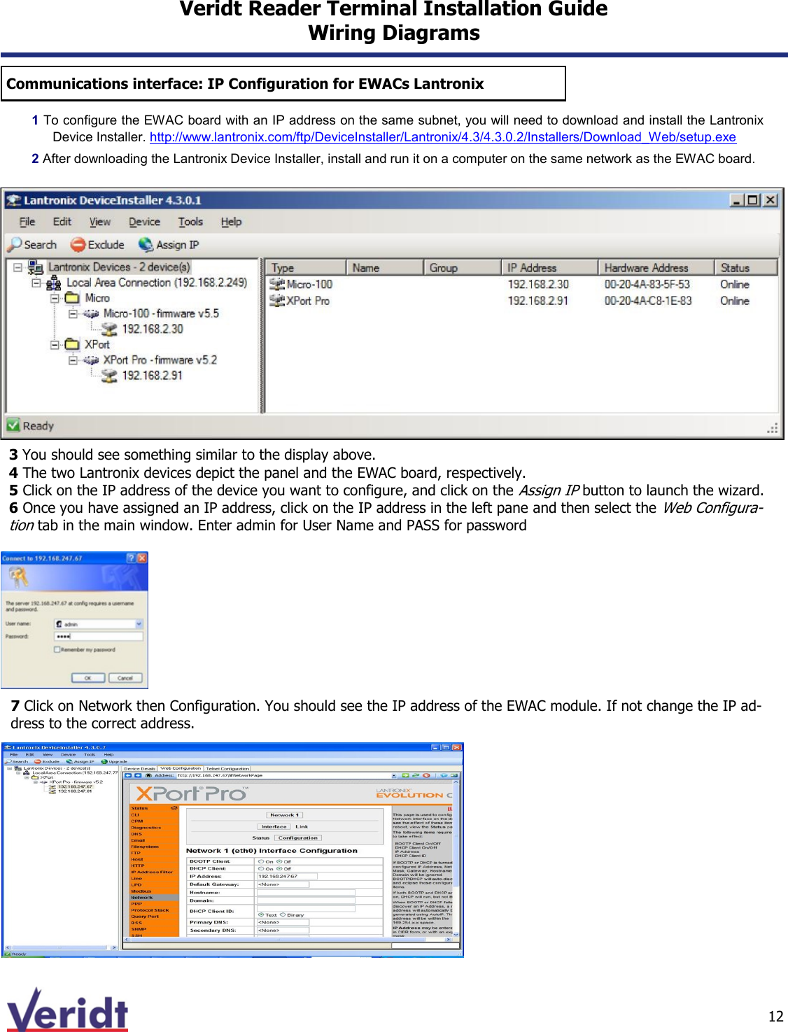
![11 Veridt Reader Terminal Installation Guide Wiring Diagrams Communications interface: Configuring EWACs PIN Signal Wire Color 1) ground Black 2) +12V Red 3)Digital I/O LED) Tan 4) RS485 + Yellow 5) RS485 - Blue 6) not in use 7) not in use 8) not in use PIN Signal Wire Color 1) ground Black 2) Wiegand 0 Green 3) Wiegand 1 White 4) Digital I/O (LED) Tan 5) not in use PIN Signal Wire Color 1) ground Black 2) +12V Red The EWACs provides power directly to the reader. The EWACs requires 12VDC at 100 mA. This means the total power requirement will be the reader current requirement + 100mA. For example, for a two reader control panel with two Bio-metric readers for high assurance (e.g., P/N 900W1030), the total pow-er requirement will be 1100Ma at 12 VDC [(450Ma per reader + 100Ma per EWAC) X 2)]. The most relia-ble operation is insured with a separate power source. Ethernet to LAN To reader port on panel To Reader Power](https://usermanual.wiki/Veridt/STEALTH/User-Guide-2257584-Page-11.png)