Veridt STEALTH MultiMode Stealth Series User Manual Users manual
Veridt Inc MultiMode Stealth Series Users manual
Veridt >
Users manual

Stealth Series

2
Veridt Reader Terminal Installation Guide
Compliance Statements
FCC 15.105
FCC (US)
(a) For a Class A digital device or peripheral, the instructions furnished the user shall include the following or similar statement,
placed in a prominent location in the text of the manual:
Note: This equipment has been tested and found to comply with the limits for a Class A digital device, pursuant to part 15 of the
FCC Rules. These limits are designed to provide reasonable protection against harmful interference when the equipment is operated
in a commercial environment. This equipment generates, uses, and can radiate radio frequency energy and, if not installed and used
in accordance with the instruction manual, may cause harmful interference to radio communications. Operation of this equipment in
a residential area is likely to cause harmful interference in which case the user will be required to correct the interference at his own
expense.
Industry Canada ICES-003 Compliance
CAN ICES-3 (A)/NMB-3(A)
FCC 15.19
FCC (US):
This device complies with part 15 of the FCC Rules. Operation is subject to the following two conditions: (1) This device may not
cause harmful interference, and (2) this device must accept any interference received, including interference that may cause unde-
sired operation.
IC (Canada):
This device complies with Industry Canada license-exempt RSS standard(s). Operation is subject to the following two conditions:
(1) this device may not cause interference, and (2) this devicemust accept any interference, including interference that may cause
undesired operation of the device.
Cet appareil est conforme aux normes Industry Canada exemptes de licence RSS standard(s). Son fonctionnement est soumis aux
deux conditions suivantes : (1) cet appareil ne doit pas provoquer d'interférences et (2) cet appareil doit
accepter toute interférence, y compris les interférences susceptibles de provoquer un fonctionnement indésirable
FCC 15.21
IMPORTANT! Changes or modifications not expressly approved by Veridt, Inc could void the user’s authority to operate the
equipment.
IC (Canada):
IMPORTANT! Changes or modifications not expressly approved by Veridt, Inc could void the user’s authority to operate the
equipment.
IMPORTANT ! Les changements ou modifications non approuvés expressément par Veridt, Inc pourrait annuler l'autorité de l'uti-
lisateur à faire fonctionner l'équipement.
CE STANDARDS
Testing for compliance to CE requirements was performed by an independent laboratory. The unit under test was found
compliant to class B limits of part 15 of the FCC Rules.
3
Veridt Reader Terminal Installation Guide
for MultiMode Stealth™ Reader Terminals
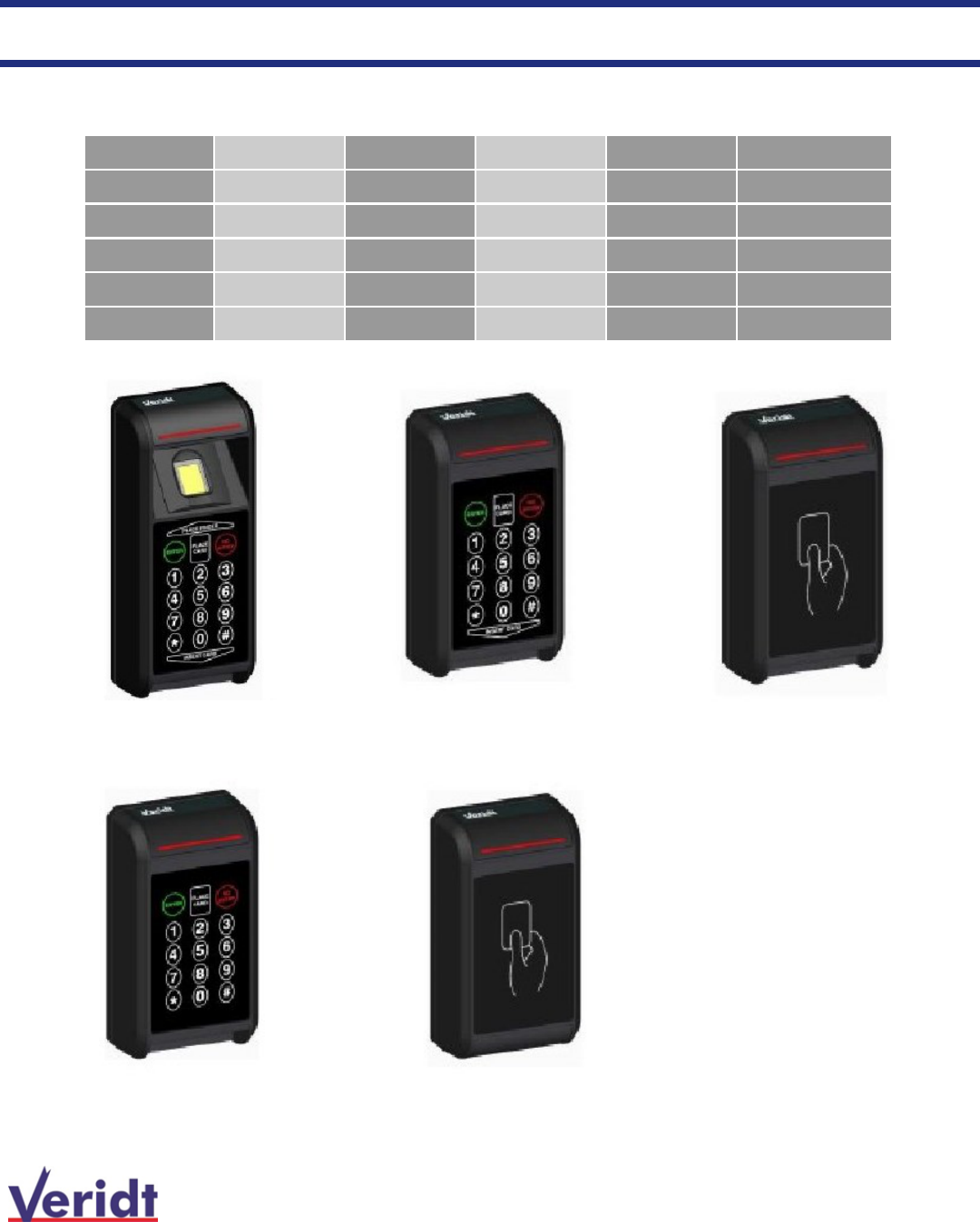
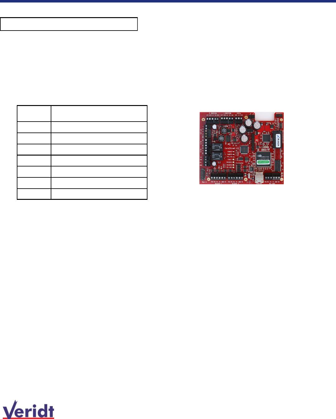
Reader P/N Contactless Contact Key Pad Biometric H” x W” x D”
900W2030 X X X X 7.0 X 3.0 X 1.6
900W2036 X X X 5.5 X 3.0 X 1.6
900W2037 X X 5.5 X 3.0 X 1.6
900W2026 X X 5.5X 3.0 X 1.6
900W2027 X 5.5X 3.0 X 1.6
Veridt Fixed Reader Terminal Hardware Configurations
This document provides installation information
for the Veridt reader hardware platforms described below
900W2026
900W2030
900W2027
900W2036
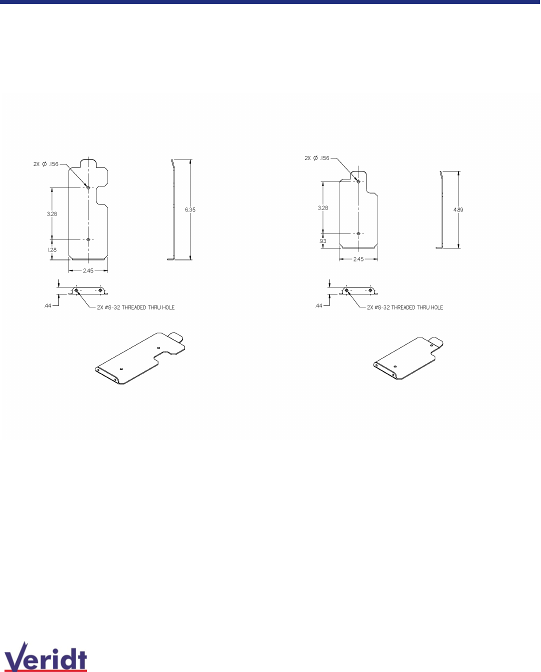
Note 2: The mounting plate fits into a re-
cessed area in the rear of the reader, so
that the reader mounts flush to the wall
and the mounting plate is completely con-
cealed. The depth measurement includes
that additional dimensional requirement of
approximately 0.35 inches.
900W2037
4
Veridt Reader Terminal Installation Guide
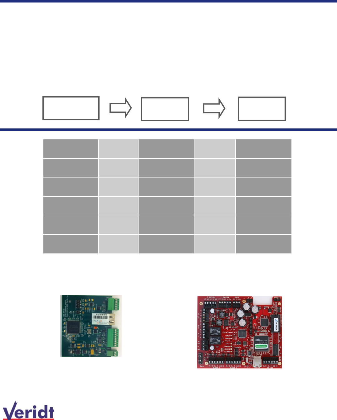
Reader Communications Options
All Veridt reader platforms are based on a common architecture and therefore installation instructions apply to all read-
ers. This common architecture allows for multiple communications interface options as well as options for interfacing to
third party software for High Assurance security solutions and Mode Control (setting the operational mode in multi-
format readers; e.g., card + PIN, card + Bio, etc.). The reader is equipped with two communications interfaces: 1)
Wiegand which can be configured up to 512 bits and 2) Serial RS-485 which can also be converted to Ethernet. The
Wiegand output is typically pre-configured for the chosen application, but is also field configurable using the MultiMode
SDK. Serial/Ethernet communications are typically preconfigured for the chosen application.
The feature set and application determines the combination of hardware and software required.
Reader Communi-
cations Interface
Hardware
Interface
Access Control
Panel
Communica-
tions Interface
Hardware
Interface
Software
Wiegand None
Wiegand
RS-485
Half duplex
None
RS-485 Half duplex Veridt EWACs pivCLASS PACS
Service Admin
RS-485 Half duplex Veridt EWACs Veridt Mode
Control
RS-485 Full duplex HID PAM pivCLASS PACS
Service Admin
Veridt EWAC
Communications Interface HID
PAM

5
Veridt Reader Terminal Installation Guide
Reader Mode Selections for Communication Option Selected
Wiegand Wiegand
RS-485
Wiegand
RS-485/Vlinx
pivCLASS
RS-485
EWACs
pivCLASS
RS-485
EWACs Mode
Control
RS-485
HID PAM
1
Card Only Card Only
(no PKI)
CHUID
(TWIC)
CHUID (TWIC) Card Only (no
PKI)
CHUID(PIV)
2
Card + PIN
(no PKI)
CAK(TWIC) CAK(TWIC) Card + PIN
(no PKI)
CAK(PIV)
3
Card + PIN
+ BIO (no
PKI)
CHUID + BIO
(TWIC)
CHUID + BIO
(TWIC)
Card + PIN +
BIO (no PKI)
PKI+ PIN (PIV)
4
CAK + BIO
(TWIC)
CHUID + CAK +
BIO (TWIC)
PKI+ PIN +
BIO (PIV)
5
CHUID (PIV)
6
CHUID + PKI
(PIV)
7
CHUID + PKI +
BIO (PIV)
8
CAK (PIV)
9
CHUID + CAK
(PIV)
10
Card Only (no
PKI)
11 Card + PIN (no
PKI)
12
Card + PIN +
PACS PIN (no
PKI)
13 Card + PIN
+BIO (no PKI)
Typical Mode of operation for Hardware / Software Combinations
Optionally available Legacy Prox Feature is configured with readers when P/N 920FW0PR is
specified.
MultiMode Stealth™ reader configured for legacy Prox 125KHz operation: includes sub-license, firmware
and additional hardware for 125KHz operation. Specify Legacy Card. Specify reader P/N. Cannot be used
with HID PAM configured readers.
6
Veridt Reader Terminal Installation Guide
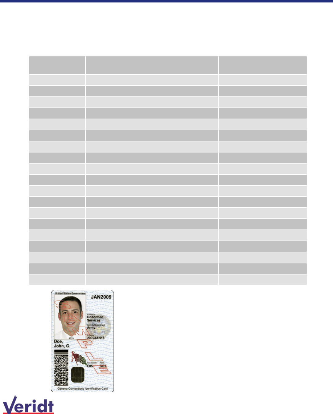
Credential Options
Veridt Readers are programed to operate in a multi-format mode to dynamically recognize a broad array
of credentials: reads GSC-IS compliant containers, PIV & PIV I, TWIC, CAC cards and any data model
based on MIFARE®, DESfire® or ISO 1443A/B cards, and ISO 7816.
ISO
Standard
Card Type Identifier
Card
Type
ISO 14443 A/B MIFARE, DESFire, DESFire EV1 Generic
ISO 7816 Generic
Dual Oberthur ID-One 128 v5.5 Dual CAC/CAC endpoint
Dual Gemalto TOP DL GX4 144K CAC/PIV endpoint
Dual Gemalto GCX4 72K DI CAC/PIV endpoint
Dual Oberthur ID One V5.2 Dual CAC/PIV endpoint
Dual Gemalto GCX4 72K DI CAC/PIV transitional
Dual Oberthur ID One V5.2 Dual CAC/PIV transitional
ISO 7816 Gemalto Access 64KV2 CAC
ISO 7816 Oberthur ID one V5.2 CAC
Dual Gemalto TOP GX4 FIPS 144K PIV
Dual Oberthur ID-One Cosmo 128 D v5.5 PIV
Dual None TWIC v1.0
Dual None TWIC v2.0
Dual Gemalto TOP GX4 FIPS 144K PIV I; PIV C (CIV)
Dual Oberthur ID-One Cosmo 128 D v5.5 PIV I; PIV C (CIV)
Dual Gemalto TOP GX4 FIPS 144K FRAC
Dual Oberthur ID-One Cosmo 128 D v5.5 FRAC
ISO 15693 None HID Prox, AWID, Indala
Card Standards:
ISO 14443A/B (13.56MHz) standard
for contactless interface based
smartcards
ISO 7816 standard for contact inter-
face based smartcards
Dual contains both contactless and
contact card read interfaces
ISO 15693 (125KHz) standard for
contactless proximity cards
7
Veridt Reader Terminal Installation Guide
Preinstallation Information
Environmental: Readers have been designed to withstand outdoor environments and are sealed from exposure to
ambient environmental conditions. However, depending on the summer and winter conditions, mounting the reader in
a suitable enclosure is recommended and in certain cases may be required. Particular attention should be given to loca-
tions in direct sunlight where UV radiation is particularly powerful and extreme weather conditions such as the cold
when readers may be intended to operate at below zero temperatures.
Reader P/N Current in mA
900W2030 400
900W2036 300
900W2037 300
900W2026 300
900W2027 300
Power requirements: Veridt reader terminals operate at 12 VDC. Power consumption will vary based on the hard-
ware configuration of the reader; e.g. fingerprint sensor, digital display, etc. Power requirements for each reader is
listed below.
Most access control panels and/or
reader control units connected to
access control panels DONOT
have adequate power for reader
devices of this type.
Power to the reader should be sup-
plied by connecting the reader
directly to the primary power sup-
ply that provides power to the pan-
el. This will insure adequate pow-
er is available to the reader for
smooth operation. Be sure to or-
der right-sized power supplies.
8
Veridt Reader Terminal Installation Guide
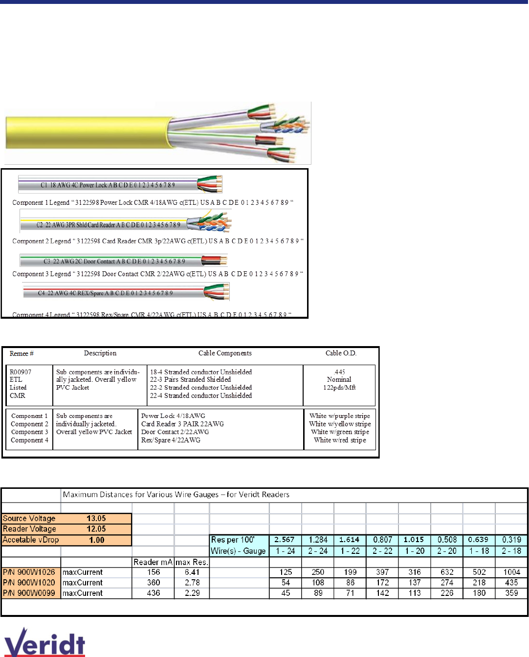
Access Control Cable
Non-Plenum
We recommend all-in-one design access control cable available by Remee:
PO Box 488 468 RT17A Florida, NY 10921
Customer Service: 800-431-3864
Website: www.remee.com
The cable is available in both Plenum and Non-Plenum configurations.
Cable Length Guide

9
Veridt Reader Terminal Installation Guide
Wiring Diagrams
Wiring diagrams for each communication option summarized on page 3 are described in
this section.
Wiegand formats are typically preconfigured for each specific application and can range
from 48 bits, 72 bits, 75 bits, 128 bits or 200 bits. All readers are configurable up to 512
Wiring from panel to reader
Color Connection
Black GND
Red Power + 12 VDC
Brown Access Granted
Blue RS485 Data+
Yellow RS485 Data-
Green Wiegand zero
White Wiegand one
Orange Tamper Switch
Communications interface: Wiegand plus RS-485
When RS-485 no used, blue and yellow wires are not connected.
10
Veridt Reader Terminal Installation Guide
Wiring Diagrams
Communications interface: RS-485 with EWACs
The MultiMode Stealth™ Reader Terminals can be configured to support comprehensive array of features and functional-
ity when configured with EWACs. The Encrypted Wiegand and Communications Interface Unit (EWAC-IU) utilizes a RS-
485 connection from the reader to the EWACs which is located at the PACS panel. The EWACs serves to:
1) provide a single connection to the reader (RS485)
2) provide bidirectional communication to the reader to set the authentication mode, request information on the
credential, send and receive status information
3) provide a mechanism for encrypting all data to and from the reader ensuring data is secured on the ”attack-
side” of the perimeter, gate, door, etc. The encryption scheme employs 128 bit AES with “anti-playback”
protection eliminating the potential of capture and “reply” of data as well as simplifying key management.
Encryption algorithms are highly embedded and conform FIPS 140-2 requirements. The encryption
feature can be selected ON/OFF through jumper settings on the EWACs.
4) provide a mechanism for transmitting data to either the PACS panel or server. After the data has been
decrypted and assembled, the type of data is determined, Wiegand or Ethernet, it is forwarded onward. Data
forwarded via Ethernet follows SSL cryptographic protocols.
5) provides a single power source to the reader.
EWACs can be configured for either Mode Control pivCLASS software suite. That configuration provides a seamless
transition to HSPD-12 or FIPS-201 compliance by leveraging a facility's physical access control system for card valida-
tion, authentication, and registration.
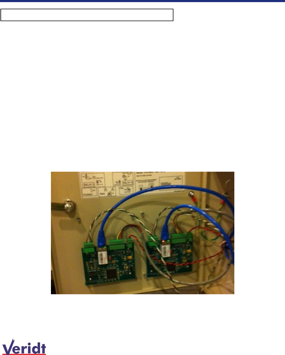
Two reader control panel configured with EWACs (each reader
requires an EWAC board). Note, Power connections and those
to the panel are shown here.
11
Veridt Reader Terminal Installation Guide
Wiring Diagrams
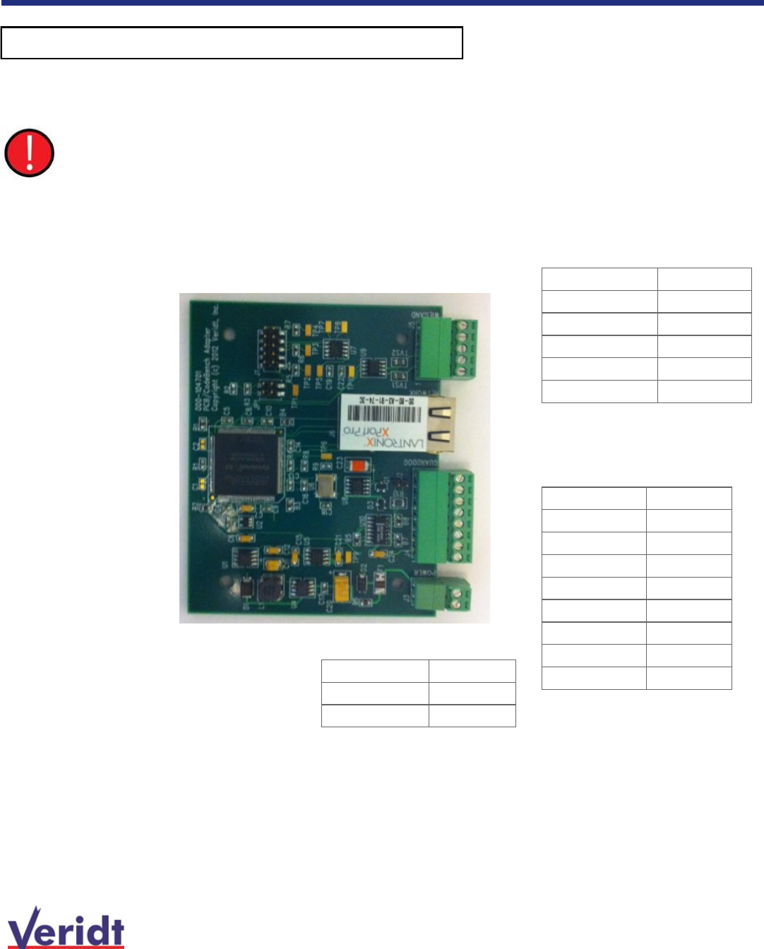
Communications interface: Configuring EWACs
PIN Signal Wire Color
1) ground Black
2) +12V Red
3)Digital I/O LED) Tan
4) RS485 + Yellow
5) RS485 - Blue
6) not in use
7) not in use
8) not in use
PIN Signal Wire Color
1) ground Black
2) Wiegand 0 Green
3) Wiegand 1 White
4) Digital I/O (LED) Tan
5) not in use
PIN Signal Wire Color
1) ground Black
2) +12V Red
The EWACs provides power directly to the reader. The EWACs requires 12VDC at 100 mA. This means
the total power requirement will be the reader current requirement + 100mA. For example, for a two
reader control panel with two Bio-metric readers for high assurance (e.g., P/N 900W1030), the total pow-
er requirement will be 1100Ma at 12 VDC [(450Ma per reader + 100Ma per EWAC) X 2)]. The most relia-
ble operation is insured with a separate power source.
Ethernet to LAN
To reader port on panel
To Reader
Power
12
Veridt Reader Terminal Installation Guide
Wiring Diagrams
Communications interface: IP Configuration for EWACs Lantronix
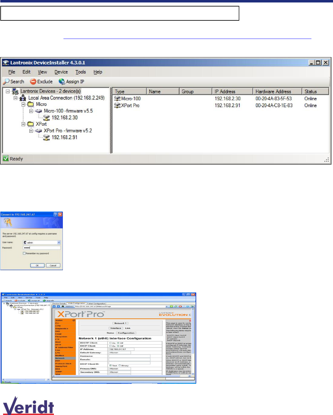
1 To configure the EWAC board with an IP address on the same subnet, you will need to download and install the Lantronix
Device Installer. http://www.lantronix.com/ftp/DeviceInstaller/Lantronix/4.3/4.3.0.2/Installers/Download_Web/setup.exe
2 After downloading the Lantronix Device Installer, install and run it on a computer on the same network as the EWAC board.
3 You should see something similar to the display above.
4 The two Lantronix devices depict the panel and the EWAC board, respectively.
5 Click on the IP address of the device you want to configure, and click on the
Assign IP
button to launch the wizard.
6 Once you have assigned an IP address, click on the IP address in the left pane and then select the
Web Configura-
tion
tab in the main window. Enter admin for User Name and PASS for password
7 Click on Network then Configuration. You should see the IP address of the EWAC module. If not change the IP ad-
dress to the correct address.
13
When configuring with pivCLASS PACS Administration Software,
please refer to the HID documentation
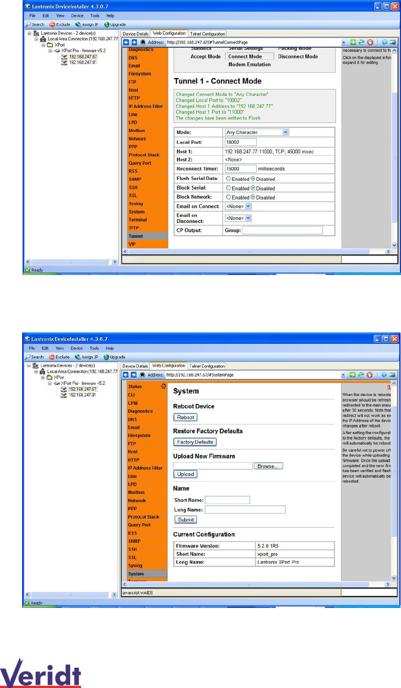
8 Click on the Tunnel tab, then Click on Connect Mode.
9 Click on the Host 1 IP address. Change the IP address to the IP address of the HID pivClass PACS Administration
Service.
10 Click on System, then Reboot. This will reboot the EWACS to the new settings.
14
Veridt Reader Terminal Installation Guide
Wiring Diagrams
Communications interface: HID PAM
Color Wiring from reader to HID
PAM
Black GND
Red Power + 12 VDC
Blue RS485 Tx-
Yellow RS485 Tx+
Gray RS485 Rx+
Purple RS485 Rx-
Orange Tamper Switch
HID PAM employs a RS485 full duplex (2 twisted pairs) for communication. This configuration is used in conjunction
with the high assurance solution comprised of pivCLASS Reader Services, pivCLASS Registration Engine and Certificate
Manager.
15
Veridt Reader Terminal Installation Guide
Installing the Reader
Stealth Bio (900W2030) Bracket Dimensions Stealth (900W2036,900W2037,900W2026,900W2027)
Bracket Dimensions
16
Made in America
Information in this publication is provided for reference and is believed to be accurate and complete. Veridt is not liable
for errors in this publication or for incidental or consequential damage in connection with the furnishing or use of the
information in this publication.
Information in this manual is intended for users of this product only and may not be reproduced, stored, transmitted, or
transferred, in whole or in part, in any form without the prior and express written permission of Veridt.
Veridt reserves the right to make changes to this publication and to the products described in it without notice. All speci-
fications and information concerning products are subject to change without notice. Reference in this publication to in-
formation or products protected by copyright or patent does not convey any license under the rights of Veridt or others.
Veridt assumes no liability arising from infringements of patents or any other rights of third parties.
VERIDT designs, develops and markets integrated reader products combining fingerprint biometrics and applied technol-
ogies for enterprise applications, and physical/logical access security requirements. VERIDT products conform to stand-
ard protocols established for United States government sector ID programs such as HSPD-12 (FIPS-201), TSA (TWIC)
and DOD (CAC) ID by utilizing VERIDT proprietary protocols and algorithms. Applied technologies combined with finger-
print biometrics include smart card technologies, other data storage forms and applications specific communication pro-
tocols to create fixed based as well as mobile, wireless and portable biometric based solutions. VERIDT products can
provide functionality ranging from fingerprint capture to on-board dedicated ID verification.
© 2007 ©2008 © 2009 ©2010 ©2012 ©2013 by Veridt Inc. All rights reserved.
Veridt, Inc.
7182 US Highway 14, Ste 401, Middleton , WI 53562 | voice +608-833-1840 | facsimile +608-833-1806
Intelligent Credential Reader Solutions
www.veridt.com
Veridt Reader Terminal Installation Guide
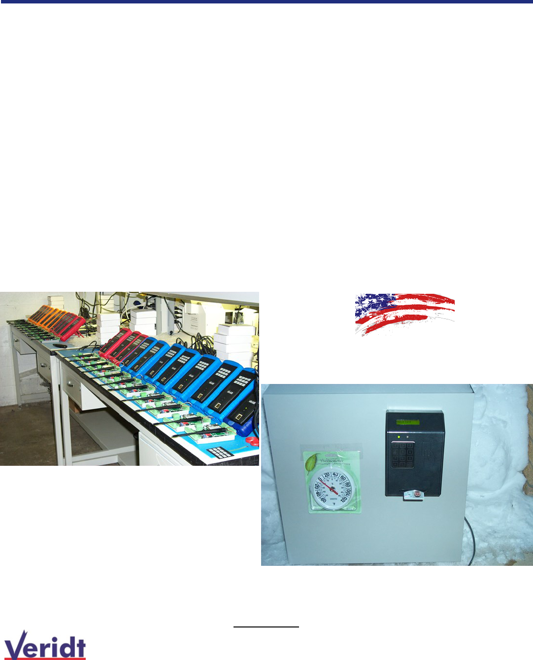
Built and Tested in Middleton, Wisconsin
Wireless handheld readers in production
Cold weather testing in the snow at minus 2 degrees F