Contents
- 1. Manual
- 2. Manual Add PP
- 3. Manual Add QX
Manual
VeriFone Part Number 28610, Revision A
PINpad 1000SE CTLS
Installation Guide
All rights reserved. No part of the contents of this document may be reproduced or transmitted in any form without the written
permission of VeriFone, Inc.
The information contained in this document is subject to change without notice. Although VeriFone has attempted to ensure the
accuracy of the contents of this document, this document may include errors or omissions. The examples and sample programs are
for illustration only and may not be suited for your purpose. You should verify the applicability of any example or sample program
before placing the software into productive use. This document, including without limitation the examples and software programs, is
supplied “As-Is.”
VeriFone, Inc.
2099 Gateway Place, Suite 600
San Jose, CA, 95110 USA
www.verifone.com
VeriFone Part Number 28610, Revision A
PINpad 1000SE CTLS Installation Guide
© 2009 VeriFone, Inc.
VeriFone, the VeriFone logo, NURIT, Omni, VeriCentre, Verix, and ZonTalk are registered trademarks of VeriFone. Other brand
names or trademarks associated with VeriFone’s products and services are trademarks of VeriFone, Inc.
All other brand names and trademarks appearing in this manual are the property of their respective holders.
Comments? Please e-mail all comments on this document to your local VeriFone Support Team.

PINPAD 1000SE INSTALLATION GUIDE 1
CONTENTS
PREFACE . . . . . . . . . . . . . . . . . . . . . . . . . . . . . . . . . . . . . . . 3
Audience. . . . . . . . . . . . . . . . . . . . . . . . . . . . . . . . . . . . . . . . . . . . . . . . . . . . . . . . 3
Organization . . . . . . . . . . . . . . . . . . . . . . . . . . . . . . . . . . . . . . . . . . . . . . . . . . . . . 3
Related Documentation . . . . . . . . . . . . . . . . . . . . . . . . . . . . . . . . . . . . . . . . . . . . 3
Guide Conventions. . . . . . . . . . . . . . . . . . . . . . . . . . . . . . . . . . . . . . . . . . . . . . . . 4
Acronym Definitions . . . . . . . . . . . . . . . . . . . . . . . . . . . . . . . . . . . . . . . . . . . . 4
CHAPTER 1
Overview PINpad 1000SE CTLS. . . . . . . . . . . . . . . . . . . . . . . . . . . . . . . . . . . . . . . . . . . . . . 5
Features and Benefits . . . . . . . . . . . . . . . . . . . . . . . . . . . . . . . . . . . . . . . . . . . . . 6
CHAPTER 2
Setup Selecting Location . . . . . . . . . . . . . . . . . . . . . . . . . . . . . . . . . . . . . . . . . . . . . . . . 9
Environmental Factors . . . . . . . . . . . . . . . . . . . . . . . . . . . . . . . . . . . . . . . . . . 9
Electrical Considerations . . . . . . . . . . . . . . . . . . . . . . . . . . . . . . . . . . . . . . . 10
Unpacking Shipping Carton . . . . . . . . . . . . . . . . . . . . . . . . . . . . . . . . . . . . . . . . 10
Examining Features . . . . . . . . . . . . . . . . . . . . . . . . . . . . . . . . . . . . . . . . . . . . . . 11
Connecting Unit to Controller . . . . . . . . . . . . . . . . . . . . . . . . . . . . . . . . . . . . . . . 12
Connecting Unit to a PC and ECR (optional) . . . . . . . . . . . . . . . . . . . . . . . . . . . 13
Connecting via USB . . . . . . . . . . . . . . . . . . . . . . . . . . . . . . . . . . . . . . . . . . . . . . 14
Contactless Support . . . . . . . . . . . . . . . . . . . . . . . . . . . . . . . . . . . . . . . . . . . . . . 14
Selecting Contactless Device Modes . . . . . . . . . . . . . . . . . . . . . . . . . . . . . . 14
Install/Replace SAM Card . . . . . . . . . . . . . . . . . . . . . . . . . . . . . . . . . . . . . . . . . 15
Processing Contactless Transactions. . . . . . . . . . . . . . . . . . . . . . . . . . . . . . 17
Using the Stand Adapter . . . . . . . . . . . . . . . . . . . . . . . . . . . . . . . . . . . . . . . . . . 17
Mounting the Adapter to Plate . . . . . . . . . . . . . . . . . . . . . . . . . . . . . . . . . . . 17
Screw-Mounting the Adapter . . . . . . . . . . . . . . . . . . . . . . . . . . . . . . . . . . . . 18
Using the Stand Adapter. . . . . . . . . . . . . . . . . . . . . . . . . . . . . . . . . . . . . . . . 18
Using the Privacy Shield. . . . . . . . . . . . . . . . . . . . . . . . . . . . . . . . . . . . . . . . . . . 19
Using the Unit. . . . . . . . . . . . . . . . . . . . . . . . . . . . . . . . . . . . . . . . . . . . . . . . . . . 19
Startup . . . . . . . . . . . . . . . . . . . . . . . . . . . . . . . . . . . . . . . . . . . . . . . . . . . . . 19
Idle Prompt . . . . . . . . . . . . . . . . . . . . . . . . . . . . . . . . . . . . . . . . . . . . . . . . . . 19
Keypad . . . . . . . . . . . . . . . . . . . . . . . . . . . . . . . . . . . . . . . . . . . . . . . . . . . . . 19
CHAPTER 3
Specifications Unit Power Requirements. . . . . . . . . . . . . . . . . . . . . . . . . . . . . . . . . . . . . . . . . . 21
Temperature. . . . . . . . . . . . . . . . . . . . . . . . . . . . . . . . . . . . . . . . . . . . . . . . . . . . 21
Humidity . . . . . . . . . . . . . . . . . . . . . . . . . . . . . . . . . . . . . . . . . . . . . . . . . . . . . . . 21
External Dimensions. . . . . . . . . . . . . . . . . . . . . . . . . . . . . . . . . . . . . . . . . . . . . . 21
Weight . . . . . . . . . . . . . . . . . . . . . . . . . . . . . . . . . . . . . . . . . . . . . . . . . . . . . . . . 21
CHAPTER 4
Service and Support Maintenance and Cleaning. . . . . . . . . . . . . . . . . . . . . . . . . . . . . . . . . . . . . . . . . 23
Service Returns . . . . . . . . . . . . . . . . . . . . . . . . . . . . . . . . . . . . . . . . . . . . . . . . . 23
Accessories and Documentation . . . . . . . . . . . . . . . . . . . . . . . . . . . . . . . . . . . . 25
Cables. . . . . . . . . . . . . . . . . . . . . . . . . . . . . . . . . . . . . . . . . . . . . . . . . . . . . . 25

2PINPAD 1000SE INSTALLATION GUIDE
Power Supply . . . . . . . . . . . . . . . . . . . . . . . . . . . . . . . . . . . . . . . . . . . . . . . . 25
PC/AT Interface Kits . . . . . . . . . . . . . . . . . . . . . . . . . . . . . . . . . . . . . . . . . . . 26
Supplementary Hardware . . . . . . . . . . . . . . . . . . . . . . . . . . . . . . . . . . . . . . . 26
Cleaning Kit. . . . . . . . . . . . . . . . . . . . . . . . . . . . . . . . . . . . . . . . . . . . . . . . . . 26
Documentation . . . . . . . . . . . . . . . . . . . . . . . . . . . . . . . . . . . . . . . . . . . . . . . 26
CHAPTER 5
Troubleshooting
Guidelines
Display Panel Does Not Work . . . . . . . . . . . . . . . . . . . . . . . . . . . . . . . . . . . . . . 27
Keypad Does Not Respond . . . . . . . . . . . . . . . . . . . . . . . . . . . . . . . . . . . . . . . . 27
PINPAD 1000SE CTLS INSTALLATION GUIDE 5
CHAPTER 1
Overview
This chapter provides a brief description of VeriFone’s PINpad 1000SE CTLS.
PINpad 1000SE
CTLS
The PINpad 1000SE CTLS is a peripheral data entry device that accepts and
encrypts Personal Identification Numbers (PINs) in addition to accepting
contactless card input. Typically, a PIN is a four- to twelve-digit code, known only
by the customer and the issuer. A PIN is requested during a transaction to verify
that a customer is authorized to use the account (card) offered. The PIN also
serves as the electronic signature for the credit or debit transaction. The
contactless card reader allows user to quickly pay for items using their contactless
card and tapping it on the device, thus completing the transaction without further
input.
Figure 1 PINpad 1000SE CTLS
VeriFone’s PINpad 1000SE CTLS builds on the success of existing
PINpad 1000SE products by integrating further functionality to create a solution for
PIN and contactless card entry. The product continues to offer high security and
functional ergonomics in addition to backwards compatibility with PCI approved
PINpad 1000SE.
The PINpad 1000SE CTLS provides the perfect solution for acquirers, processors,
and merchants looking to capitalize on the expanding payment options in the debit
arena. Card issuers are pushing contactless offerings and this product allows the
merchant to take advantage of both existing PIN debit and contactless. This
compact, easy-to-use, device connects to most existing point-of-sale (POS)
controllers such as Vx or NURIT transaction terminals, as well as most ECR
based systems on the market.

OVERVIEW
Features and Benefits
6PINPAD 1000SE CTLS INSTALLATION GUIDE
The PCI-compliant PINpad 1000SE CTLS incorporates a broad array of
sophisticated security features to guard against fraud and abuse. This includes
full support for the 3DES encryption standard, and a choice of Master/Session or
DUKPT (Derived Unique Key Per Transaction) key management methods. The
PINpad 1000SE CTLS also supports MAC (Message Authentication Code) to
protect debit transaction data from accidental or fraudulent tampering during
transfer to its host. The device is also certified to accept a broad array of MSD and
EMV contactless based payment, including Visa, Mastercard, American Express
and Discover.
The PINpad 1000SE CTLS features great ergonomic features such as large, hard-
rubber keys for ease of use, and a sleek design that fits in the palm of the hand or
can be counter mounted. The device is rugged and reliable, built to withstand
rough handling at the point-of-sale. Most importantly, the PINpad 1000SE CTLS
PCI is fully compatible with existing PCI PINpad 1000SE.
Features and
Benefits
Exceptional Ease of Use and Ergonomics
•Contactless logo placement on lens of device for optimized user experience.
•Bright LEDs for both customer and merchant viewing of transaction process.
•Sleek and stylish shape occupies minimal counter space.
•Bold, ergonomic design fits comfortably in the palm of a hand.
•Waisted area for an easy and secure grip.
•Large, hard-rubber keys provide improved tactile feedback, minimizing errors
and maximizing ease-of-use for consumers of all ages.
•Intuitive telco-style interface and colored control keys simplify training and
reduce support requests.
•Programmable function keys allows selection of functions within an
application.
•Highly readable optional backlit 128x32 graphic liquid crystal display (LCD),
which supports multiple languages for global applications.
•Font generation tool kit allows easy language set-up with multiple size fonts.
Critical Security Protection
•VeriFone’s advanced contactless architecture future proofs your investment
with Single Contactless Interface (SingleCI), SoftSAMs, and side by side
application architecture
•Supports 3DES, Verishield Security Scripts, Master/Session and DUKPT key
management.
•Offers secure, reliable PIN input for expanding range of PIN-based
transactions.
•PCI approved for secure, reliable PIN entry.

OVERVIEW
Features and Benefits
PINPAD 1000SE CTLS INSTALLATION GUIDE 7
•Meets ISO and ANSI standards for PIN encryption, key management, and
MAC.
•Key injection simplified and secured with VeriFone’s SecureKit key loading
software.
•Rugged and reliable design absorbs hard knocks found at POS.
•Removable privacy shield offers option of supplemental physical security.
•Well-planned shape works with existing VeriFone PINpad stands and wall- or
counter-mounting hardware.
•Connects with most POS payment terminals, PCs, and ECRs.
•Backward-compatible with VeriFone’s legacy PINpad 1000SE.
•Compatible with existing PINpad 1000 stands, and wall- or counter-mounting
hardware.
•USB connectivity that gives another option to connect with payment terminals,
personal computers, and electronic cash registers (ECRs).
•Supports payment transactions in a variety of payment environments.

OVERVIEW
Features and Benefits
8PINPAD 1000SE CTLS INSTALLATION GUIDE

PINPAD 1000SE CTLS INSTALLATION GUIDE 3
PREFACE
This guide is the primary source of information for setting up and installing a
PINpad 1000SE CTLS device.
Audience This guide provides simple descriptions of the PINpad 1000SE CTLS features, as
well as basic information for installing and configuring a PINpad 1000SE CTLS.
Organization This guide is organized as follows:
Chapter 1, Overview. Provides an overview of a PINpad 1000SE CTLS terminal.
Chapter 2, Setup. Explains how to set up and install the PINpad 1000SE CTLS as
well as how to select a location and establish connections with other devices.
Chapter 3, Specifications. Discusses the power requirements and dimensions of
PINpad 1000SE CTLS.
Chapter 4, Service and Support. Provides information on contacting your
VeriFone service provider, ordering accessories or documentation from VeriFone,
and maintaining the PINpad 1000SE CTLS.
Chapter 5, Troubleshooting Guidelines. Provides troubleshooting guidelines,
should you encounter a problem in terminal installation and configuration.
Related
Documentation
To learn more about the PINpad 1000SE CTLS, you may look at the following
documents and their associated VeriFone Part Numbers (VPN):
•PINpad 1000SE CTLS Certifications and
Regulations
VPN - DOC115EN06-A
•PINpad 1000SE CTLS Quick Installation Guide VPN - DOC115EN05-A
•PINpad 1000SE Reference and Programmers
Guide
VPN - 26803
•PINpad 1000SE Stand Adapter Quick
Installation Guide
VPN - DOC115EN03-A
PREFACE
Guide Conventions
4PINPAD 1000SE CTLS INSTALLATION GUIDE
Guide
Conventions
Various conventions are used to help you quickly identify special formatting.
Table 1 describes these conventions and provides examples of their use.
Acronym Definitions
Various acronyms are used in place of the full definition. Table 2 presents
acronyms and their definitions.
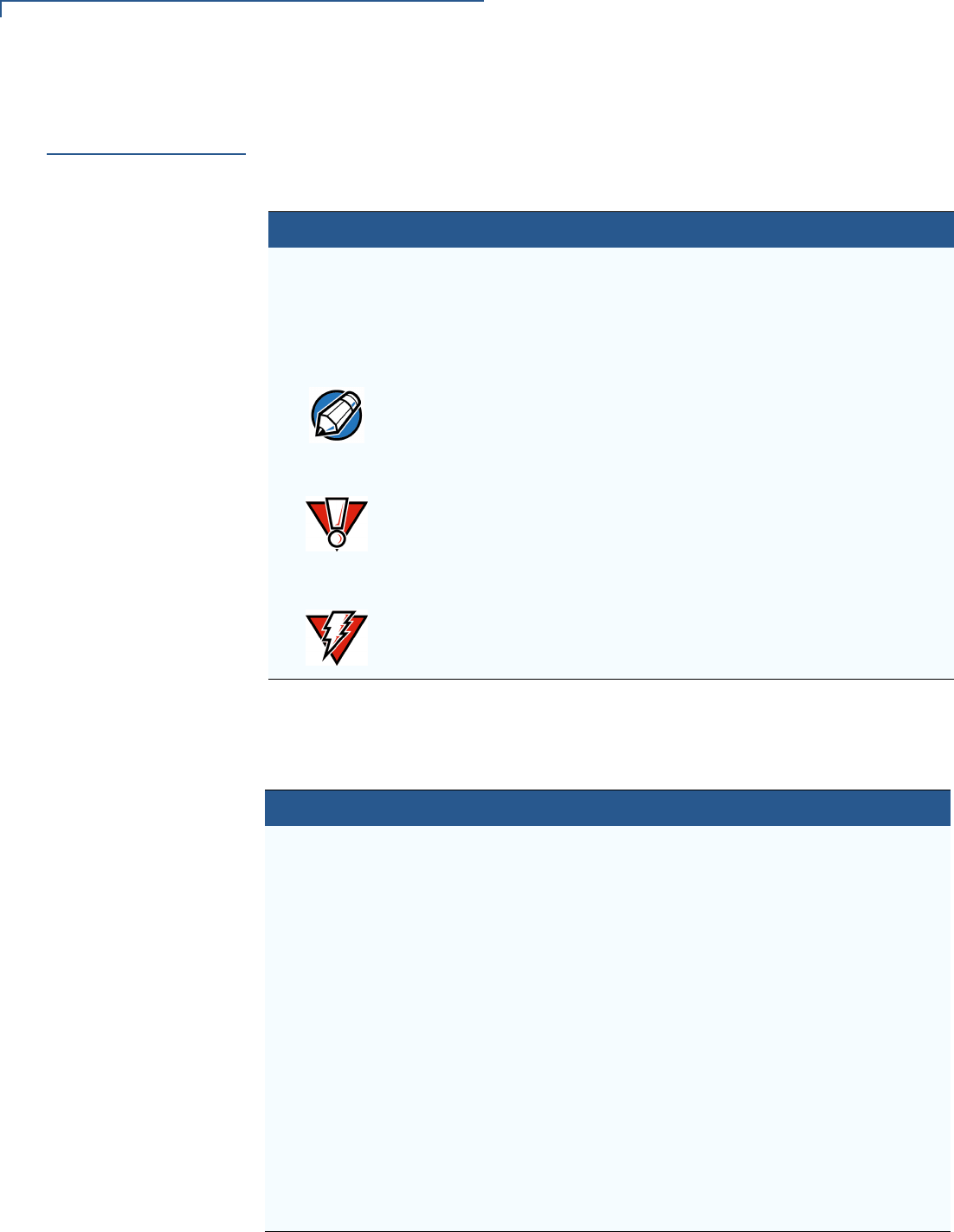
Table 1 Document Conventions
Convention Meaning Example
Blue Text in blue indicates terms that
are cross references.
See Guide Conventions.
Italics Italic typeface indicates book
titles or emphasis.
You must not use this unit
underwater.
The pencil icon is used to
highlight important information.
RS232-type devices do not work
on the PINpad 1000SE CTLS
communication port.
The caution symbol indicates
hardware or software failure, or
loss of data.
The unit is not waterproof or
dustproof, and is intended for
indoor use only.
The lighting symbol is used as a
warning when bodily injury might
occur.
Due to risk of shock do not use
the terminal near water.
NOTE
CAUTION
WARNING
Table 2 Acronym Definitions
Acronym Definitions
DEA/DES Data Encryption Algorithm/Standard, as defined in ANSI X3.92
DUKPT Derived Unique Key Per Transaction Method as defined in the
VISA’s POS Equipment Requirement: PIN processing and Data
Authentication, International Version 1.0, August 1988
EBT Electronic Benefits Transfer
ECR Electronic Cash Register
LED Light Emitting Diode
LCD Liquid Crystal Display
MAC Message Authentication Code, as defined in ANSI X9.19
PED PIN Entry Device
PIN Personal Identification Number
POS Point-of-Sale
RFID Radio Frequency Identification
SAM Secure Access Module
USB Universal Serial Bus

PINPAD 1000SE CTLS INSTALLATION GUIDE 9
CHAPTER 2
Setup
This chapter describes the setup procedure for the PINpad 1000SE CTLS, in the
following sections:
•Selecting Location
•Unpacking Shipping Carton
•Examining Features
•Connecting Unit to Controller
•Connecting Unit to a PC and ECR (optional)
•Connecting via USB
•Using the Stand Adapter
•Using the Privacy Shield
•Using the Unit
Selecting
Location
Use the following guidelines to select the best location for the PINpad 1000SE
CTLS.
To Select a Location
•Select a location convenient for both merchant and cardholder.
•Select a location that is far from heavy metal objects.
•Select a flat support surface, such as a countertop or table.
•Select a location near a power outlet and the terminal or computer connected
to the PINpad 1000SE CTLS unit.
Environmental
Factors
•Do not use the unit where there is high heat, dust, humidity, moisture, or
caustic chemicals or oils.
•Keep the unit away from direct sunlight and anything that radiates heat, such
as a stove or a motor.
WARNING
For safety, do not string cables or cords across a walkway.
SETUP
Unpacking Shipping Carton
10 PINPAD 1000SE CTLS INSTALLATION GUIDE
•Do not use the PINpad 1000SE CTLS outdoors.
Electrical
Considerations
•Avoid using this product during electrical storms.
•Avoid locations near electrical appliances or other devices that cause
excessive voltage fluctuations or emit electrical noise (for example, air
conditioners, electric motors, neon signs, high-frequency or magnetic security
devices, or computer equipment).
•Do not use the PINpad 1000SE CTLS unit water or in moist conditions.
•Disconnect the device from its POS terminal before cleaning.
Unpacking
Shipping Carton
Carefully inspect the shipping carton and its content for possible tampering or
damage.
1Remove the PINpad 1000SE CTLS from the shipping carton.
2Remove any protective plastic wrap and place the unit on a table or
countertop.
3Remove the clear protective film from the display.
4Replace all the packing materials, close the lid, and save the carton for
repacking or moving the PINpad 1000SE CTLS in the future.
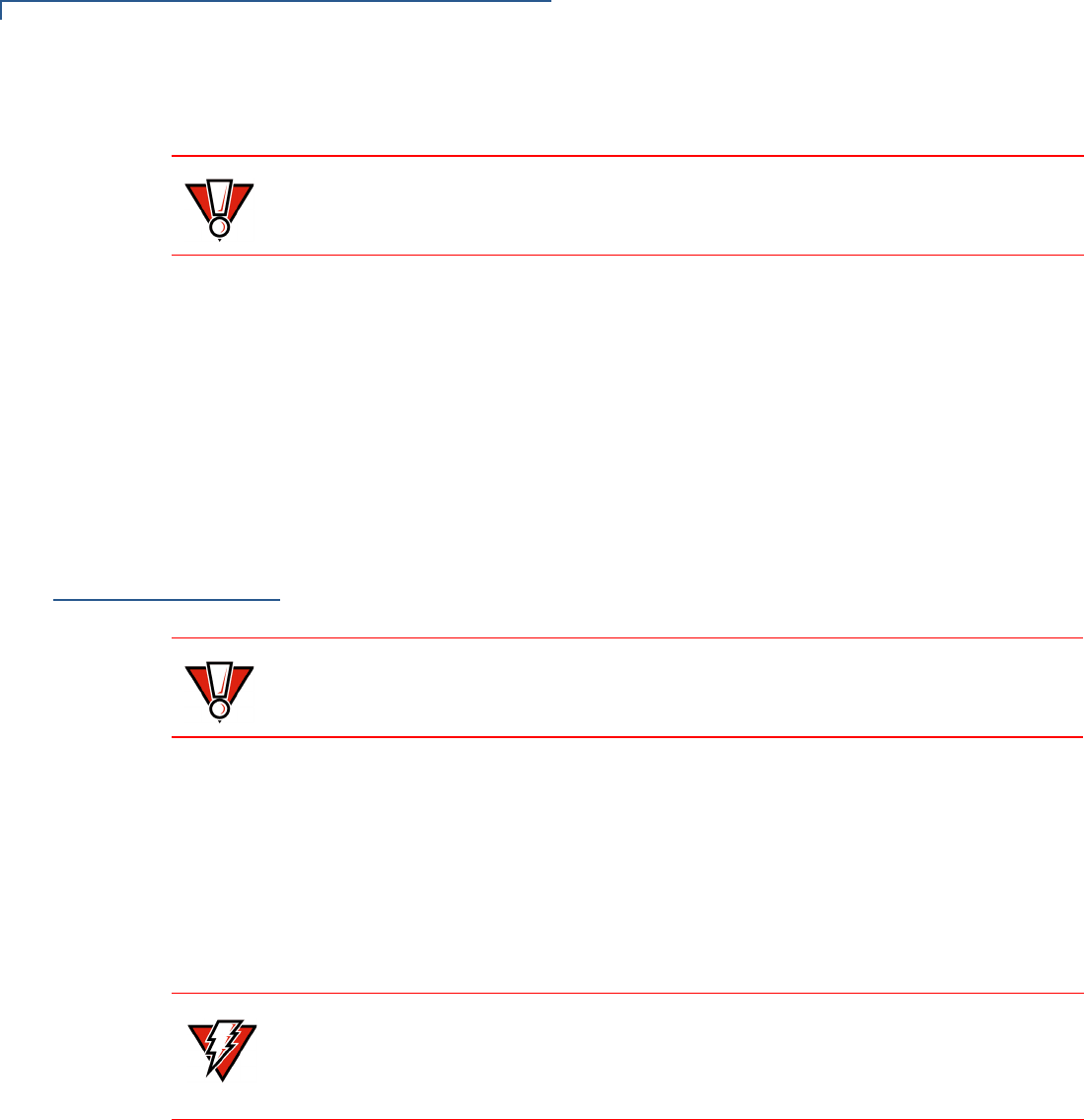
CAUTION The PINpad 1000SE CTLS is not waterproof or dustproof, and is intended for
indoor use only. Any damage to the unit from exposure to rain or dust can void any
warranty.
CAUTION
The PINpad 1000SE CTLS is a secure product and any tampering can cause it to
cease to function or operate in an unsecured manner.
WARNING Do not use a unit that has been tampered with or otherwise damaged.The
PINpad 1000SE CTLS comes equipped with tamper-evident label. If a label or
component appears damaged, immediately notify the shipping company and your
VeriFone representative or service provider immediately.
SETUP
Examining Features
PINPAD 1000SE CTLS INSTALLATION GUIDE 11
Examining
Features
Before continuing the installation process, observe features of the PINpad 1000SE
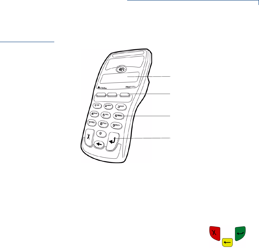
CTLS. Figure 2 illustrates the basic features:
Figure 2 PINpad 1000SE CTLS Features
The PINpad 1000SE CTLS includes the following features:
•A display.
•Three types of keys:
•A 10-key, telco-style keypad.
•Three unlabeled, programmable function keys above the keypad.
•Three color-coded function keys below the keypad
(icons at right, left-to-right: CANCEL, BACKSPACE,
ENTER).
DISPLAY
TELCO-STYLE KEYPAD
PROGRAMMABLE FUNCTION KEYS
COLOR-CODED FUNCTION KEYS
SETUP
Connecting Unit to Controller
12 PINPAD 1000SE CTLS INSTALLATION GUIDE
Connecting Unit
to Controller
The PINpad 1000SE CTLS rear panel has a modular, four-wire interface port for
power and communication connection to the controller. The connection methods
differ between two specific versions of the PINpad 1000SE CTLS – USB and RS-
232. This section discusses a connection to the RS-232 version of the
PINpad 1000SE CTLS.
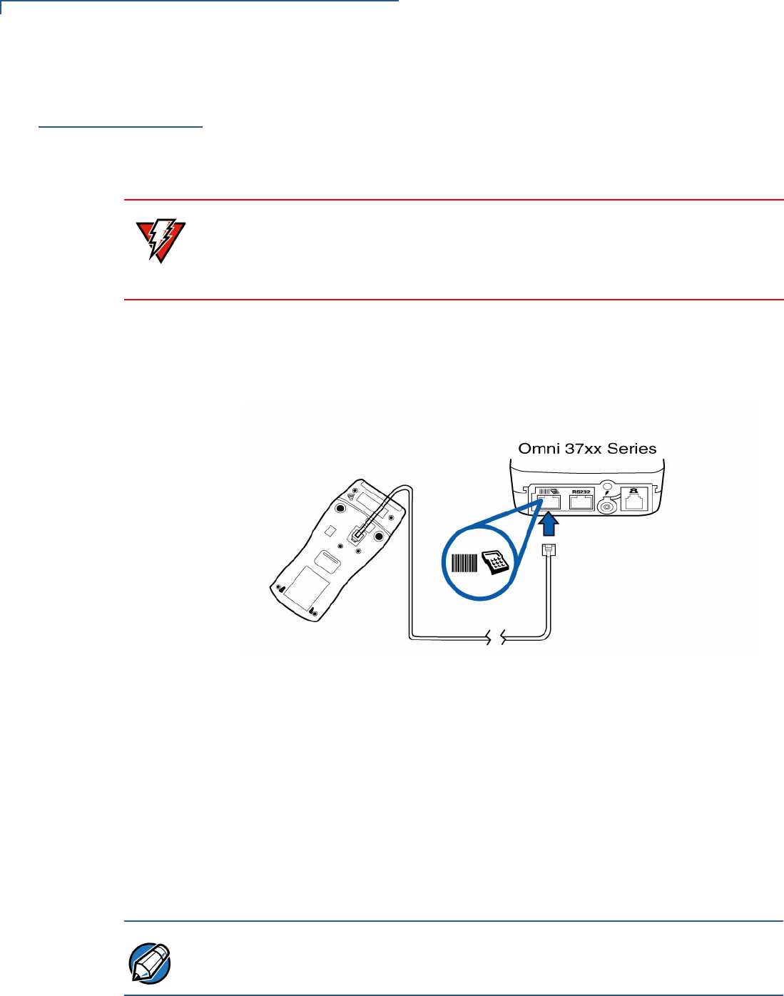
Figure 3 illustrates how to connect the PINpad 1000SE CTLS to a Omni 37xx
series terminal. For other terminal or controller connections, refer to the reference
manual for that controller.
Figure 3 PINpad 1000SE CTLS and Terminal Cable Connections
1Disconnect power from the terminal or ECR.
2Position the PINpad 1000SE CTLS face down on a soft, smooth surface to
avoid damaging the keypad or display.
3Connect the modular plug on the cable to the modular jack on the rear of the
PINpad 1000SE CTLS device.
4Connect the other end of the cable to the PlN pad port on the rear of the
terminal.
5Reconnect power to the terminal.
WARNING Turn off or unplug the controller when connecting or disconnecting the
PINpad 1000SE CTLS. Memory corruption and data loss can result if the controller
is processing data when power is removed.
Refer to the controller device instructions for any controller-specific warnings.
NOTE For cable removal, use the same steps described above in reverse. If exchanging
cables, use a VeriFone-approved cable. For more information, refer to
PINpad 1000SE CTLS Quick Installation Guide, VPN - DOC115EN05-A.
SETUP
Connecting Unit to a PC and ECR (optional)
PINPAD 1000SE CTLS INSTALLATION GUIDE 13
Connecting Unit
to a PC and ECR
(optional)
The RS-232 version of the PINpad 1000SE CTLS also connects to a PC or ECR
thru special cable products to provide power for the PINpad 1000SE CTLS (refer
to Accessories and Documentation). These cables plug into the PINpad 1000SE
CTLS with a DB9 connector housing. The connector housing has a DC jack that
connects to a power supply for external AC power.
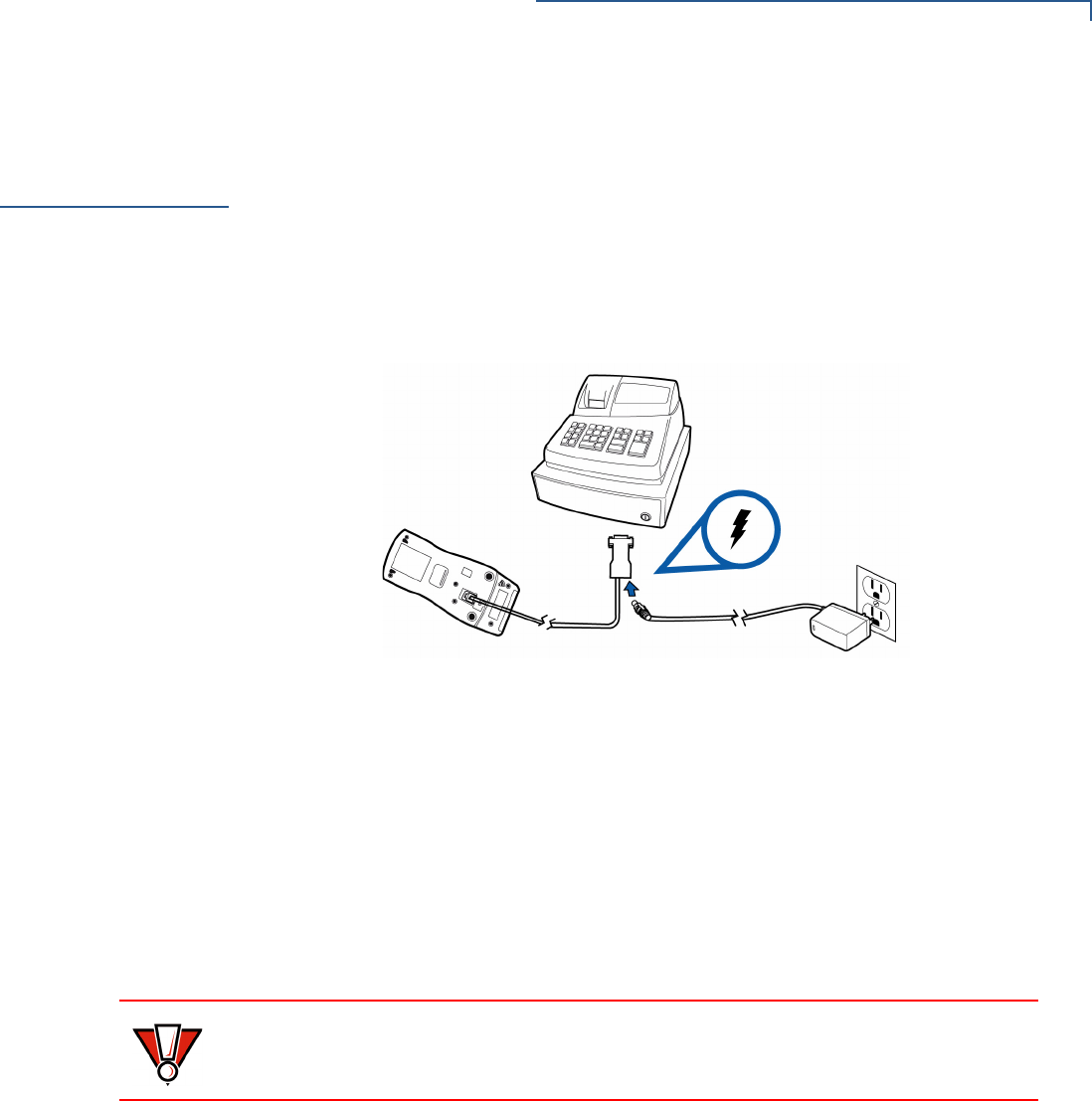
Figure 4 illustrates how to connect the PINpad 1000SE CTLS to an ECR or
compatible computers.
Figure 4 PINpad 1000SE CTLS and DB9 ECR Cable Connection
1Disconnect power from the PC/ECR.
2Connect the end of the cord with the DB9 connector to the PC/ECR.
3Connect the modular plug on the other end of the cord to the PINpad 1000SE
CTLS.
4Plug the power supply into the socket at the base of the PC/ECR connector.
5Plug the power supply into an AC wall outlet.
6Reconnect power to the PC/ECR.
CAUTION Using an incorrectly rated power supply can damage the unit or cause it not to
work properly. For U.S. – VeriFone recommends using only VPN# CPS11212-1C-
R. For other uses see Specifications for detailed power supply specifications.
SETUP
Connecting via USB
14 PINPAD 1000SE CTLS INSTALLATION GUIDE
Connecting via
USB
The USB version of the PINpad 1000SE CTLS can also be connected to a
terminal, ECR, or a host PC using a coiled USB cable (VPN#WCL115013-A).
When connecting to a PC via a USB port, the device, in either PINpad 1000SE
CTLS PCI mode or NURIT 222 mode – requires the additional installation of
device drivers.
1Connect the device to the host PC.
2Connect the cable to external power supply.
3Wait until the host PC recognizes the new hardware and starts the Found New
Hardware Wizard.
4Follow the instructions on the Found New Hardware Wizard to install the USB-
UART driver.
Contactless
Support
The PINpad 1000SE CTLS supports the global contactless program specifications
from American Express, MasterCard, Visa, and Discover with virtually no changes
to existing payment hardware or software.
Selecting
Contactless Device
Modes
To allow a PINpad 1000SE CTLS device to process contactless transactions, its
device mode should be set to Contactless. By default, operating mode of all
PINpad 1000SE CTLS devices, including the PINpad 1000SE CTLS, is set to
PINpad.
Users can switch from PINpad mode to Contactless mode thru menu options
shown at the terminal’s interface.
CAUTION
If an extension cable is required when connecting by the device’s USB port, only
USB-certified cables should be used.
NOTE Additional instructions and device drivers are found and downloaded from the
VeriFone Technical Support page:
(http://www.verifone.com/technical-support.aspx).
Browse to the INF file provided by VeriFone when specifying the driver location.
When the installation is done, check the list of ports on the Device Manager to see
the new USB device.
NOTE For more information on switching Device Modes, refer to PINpad 1000SE
Reference and Programmers Guide, VPN - 26803. Device mode refers to the
device’s current operating mode, either PINpad or Contactless.
SETUP
Install/Replace SAM Card
PINPAD 1000SE CTLS INSTALLATION GUIDE 15
Install/Replace
SAM Card
You may need to install a security access module (SAM) card or replace an old
card.
To change or install
MSAMs
1Remove the data cable from the back of the unit.
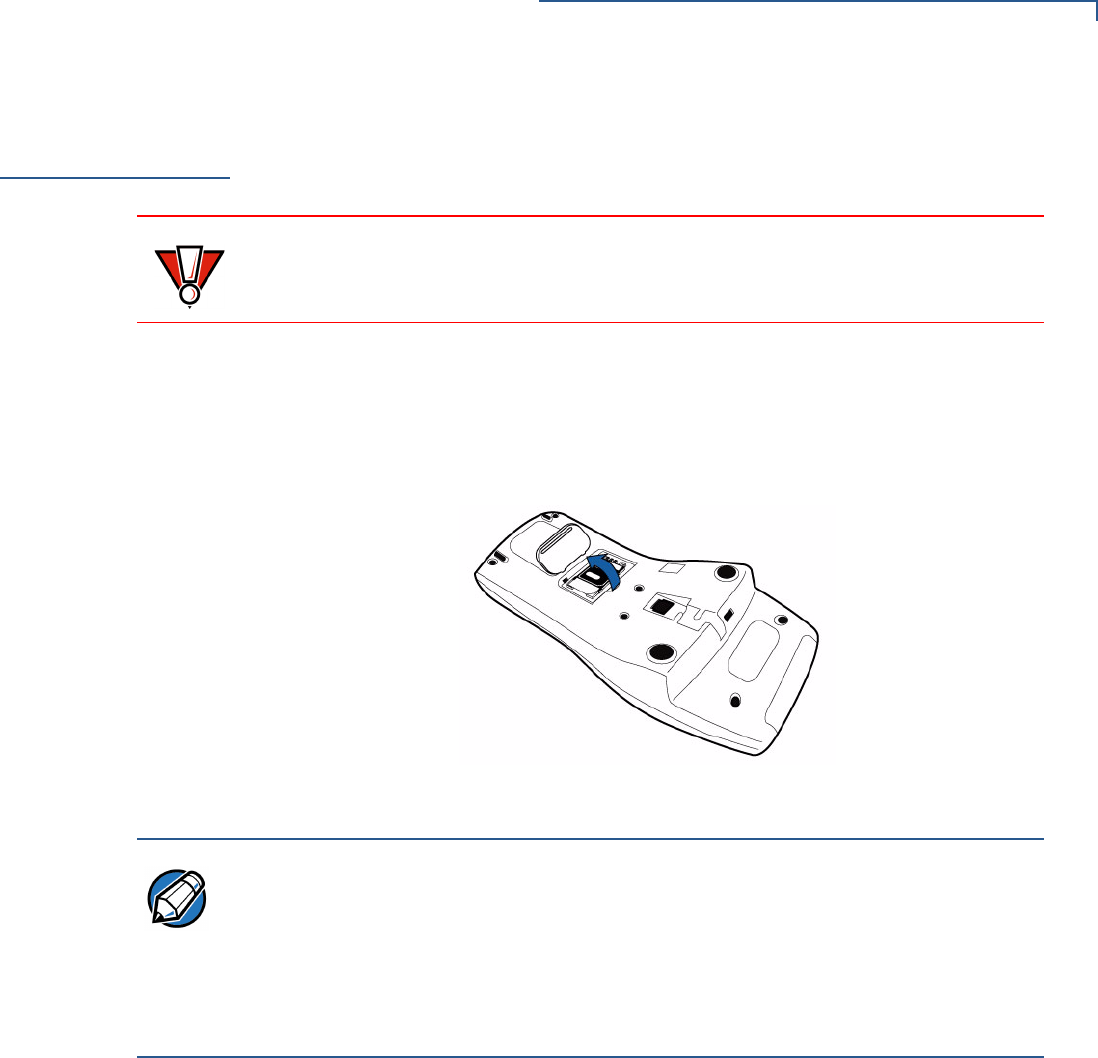
2Place the PINpad 1000SE CTLS facedown on a soft, clean surface to protect
the lens from scratches.
3Lift open the compartment door. The SAM cardholder is now accessible.
Figure 5 Opening SAM Compartment Door
CAUTION Observe standard precautions in handling electrostatically sensitive devices.
Electrostatic discharges can damage the equipment. VeriFone recommends
using a grounded anti-static wrist strap.
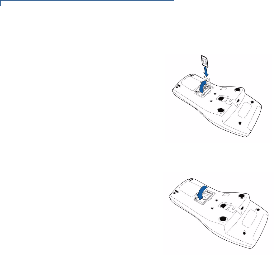
NOTE Before inserting the SAM card, position it as shown in Figure 6, with the card’s
gold contacts facing away from you, toward the unit. The cardholder slot in the
PINpad 1000SE CTLS has a set of contacts. The SAM card has a notch on one
corner to ensure that it fits into the connector base in only one way; the
PINpad 1000SE CTLS has a matching notch cast into the backside of the SAM
compartment door to ensure the SAM card is positioned correctly when the cover
is closed.
SETUP
Install/Replace SAM Card
16 PINPAD 1000SE CTLS INSTALLATION GUIDE
4Install the SAM card by aligning the card and carefully sliding it into the slot
until fully inserted.
Figure 6 SAM Insertion
5Push the SAM card holder back and close the compartment door.
Figure 7 SAM Card Holder
SETUP
Using the Stand Adapter
PINPAD 1000SE CTLS INSTALLATION GUIDE 17
Processing
Contactless
Transactions
The PINpad 1000SE CTLS is only active when signaled by an application for the
conduction of a contactless smart card transaction.
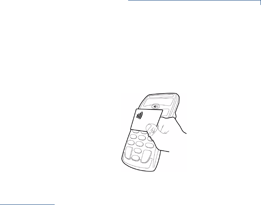
To perform a contactless smart card transaction:
1Gently tap the card onto or hold the card (within to 4 cm) against the surface of
the RFID antenna.
2A short beeping sound and the lighting of four LEDs indicates a successful
transaction.
Figure 8 PINpad 1000SE CTLS with Smart Card
Using the Stand
Adapter
The optional stand adapter holds the PINpad 1000SE CTLS securely to a
countertop or a wall. The unit can be removed from the stand adapter for
handheld operation.
Mounting the
Adapter to Plate
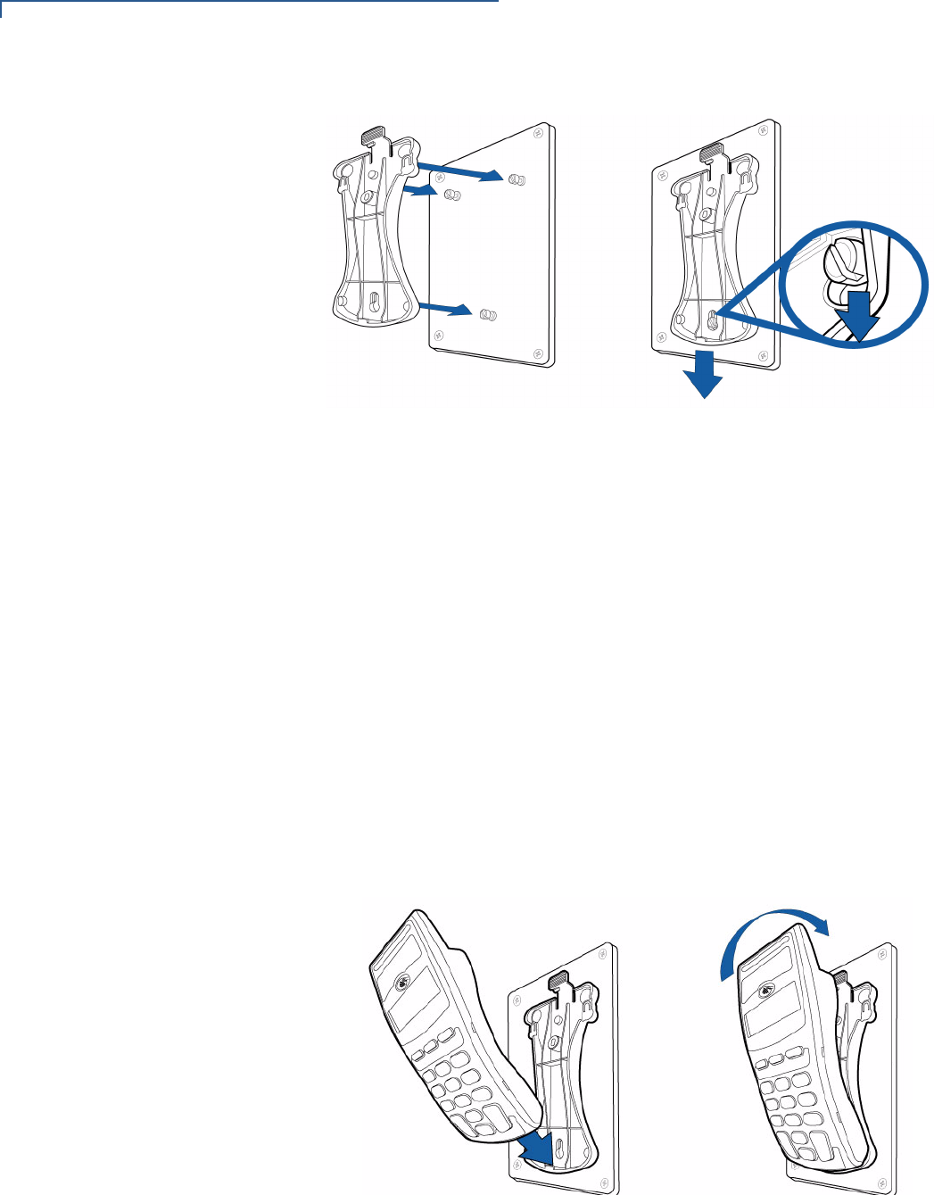
Figure 9 shows how to install a stand adapter onto a pre-existing flat mounting
plate.
1Select a location for the stand adapter on a smooth wall or countertop. Be sure
the cable can easily reach the controller from this position without stretching.
2Position the keyholes on the molded cradle over the slotted screws on
mounting plate. Slide the adapter downward until the screws are in the narrow
ends of the keyholes.
SETUP
Using the Stand Adapter
18 PINPAD 1000SE CTLS INSTALLATION GUIDE
Figure 9 Stand Adapter Installation
Screw-Mounting the
Adapter
The stand adapter may also be screwed directly to a wall or countertop.
•Use screw anchors when fastening the adapter to a cement or brick wall.
•When fastening the plate to drywall, the screws must go into the studs behind
the wall. Screw anchors alone will not safely hold the adapter to drywall.
To screw-mount the stand adaptor to the PINpad 1000SE CTLS, use American
National Standard #8 or Metric M3 screws 8 mm length, with head diameter
between 4.5 and 6.0 mm, and head thickness less than 2.5 mm. Use the stand
adaptor to mark the hole placement on the desired location, and then insert
screws, adjusting the screw depth until the unit is firmly mounted.
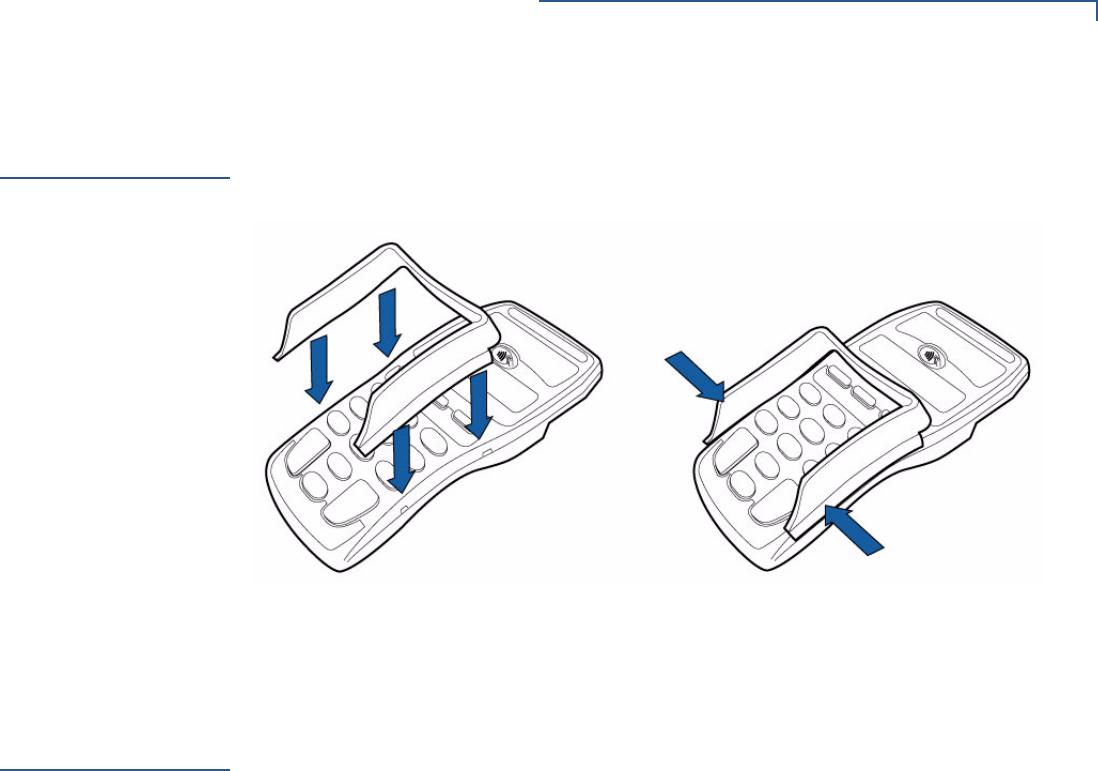
Using the Stand
Adapter
Figure 10 shows how to insert a PINpad 1000SE CTLS into a stand adapter. Slide
the end of the PINpad 1000SE CTLS into the bottom of the stand adapter, then
press the screen end of the PINpad 1000SE CTLS firmly into the top of the stand
adapter until you hear and feel the release lever click.
Figure 10 Inserting the PINpad 1000SE CTLS into the Stand Adapter
To remove the adapter, press the release lever at the top of the stand and pull the
PINpad 1000SE CTLS up and out of the stand adapter.
SETUP
Using the Privacy Shield
PINPAD 1000SE CTLS INSTALLATION GUIDE 19
Using the
Privacy Shield
Figure 11 shows an example of an installed privacy shield.
Figure 11 Installed Privacy Shield
Using the Unit
Startup Upon startup, the PINpad 1000SE CTLS briefly displays the version and date
(example: 10.24.00 06/07), followed by the idle prompt.
Idle Prompt The idle prompt indicates the PINpad 1000SE CTLS is ready for use. The default
idle prompt is a row of characters that resembles a marching arrow (<------------).
The display and sequence of the idle prompts can be programmed through an
application program written for the controller. The display has a multiple, 4-line
graphics display which may be customized to show ENTER YOUR PIN and WELCOME
messages.
In Contactless mode, the device displays the message PLEASE TAP YOUR CARD.
This message varies to accomodate client requirements.
Keypad The PINpad 1000SE CTLS has 10-key telco-style keypad that includes the letters
A through Z and numerals 0 through 9, as well as three unlabeled, programmable
function keys, and three color-coded function keys (see Figure 2).

SETUP
Using the Unit
20 PINPAD 1000SE CTLS INSTALLATION GUIDE
At the PIN request prompt, enter the PIN and press ENTER. The PINpad 1000SE
CTLS will show a processing display when the device successfully receives the
PIN entry.
NOTE Press BACKSPACE to clear the last number.
Press CANCEL to cancel the transaction.

PINPAD 1000SE CTLS INSTALLATION GUIDE 21
CHAPTER 3
Specifications
This chapter discusses power requirements, dimensions, and other specifications
of the PINpad 1000SE CTLS.
Unit Power
Requirements
Input: 7.5 v - 20 v,
Maximum current: 500 mA
Temperature Operating temperature: 0o to 50oC (32o to 122oF)
Humidity Relative humidity: up to 95%; no condensation
External
Dimensions
Weight
•Length:181 mm (7.13 in)
•Width:83 mm (3.26 in)
•Depth:41 mm (1.61 in)
•Unit weight:270 g (9.52 oz)
•Shipping weight:400 g (0.881)

SPECIFICATIONS
Weight
22 PINPAD 1000SE CTLS INSTALLATION GUIDE
PINPAD 1000SE CTLS INSTALLATION GUIDE 23
CHAPTER 4
Service and Support
Maintenance
and Cleaning
The PINpad 1000SE CTLS has no user-serviceable parts. Unless otherwise
instructed, do not, under any circumstances, attempt any service, adjustments, or
repairs on the unit. Disconnect the device before cleaning.
To clean the unit, periodically use a clean cloth, slightly dampened with water and
a drop or two of mild soap. For stubborn stains, use alcohol or an alcohol-based
cleaner. For best results, use a VeriFone Cleaning Kit (refer to Accessories and
Documentation).
Service Returns For PINpad 1000SE CTLS equipment failures that cannot be resolved by your help
desk or service department, contact one of the following hotlines for product
service and repair information:
•USA – VeriFone Service and Support Group, 1-800-834-9133,
Monday - Friday, 8 A.M. - 7 P.M., EST
•International – Contact your VeriFone representative
Before returning PINpad 1000SE CTLS to VeriFone, you must obtain a
Merchandise Return Authorization (MRA) number. The following procedure
describes how to return one or more PINpad 1000SE CTLS for repair or
replacement (U.S. customers only).
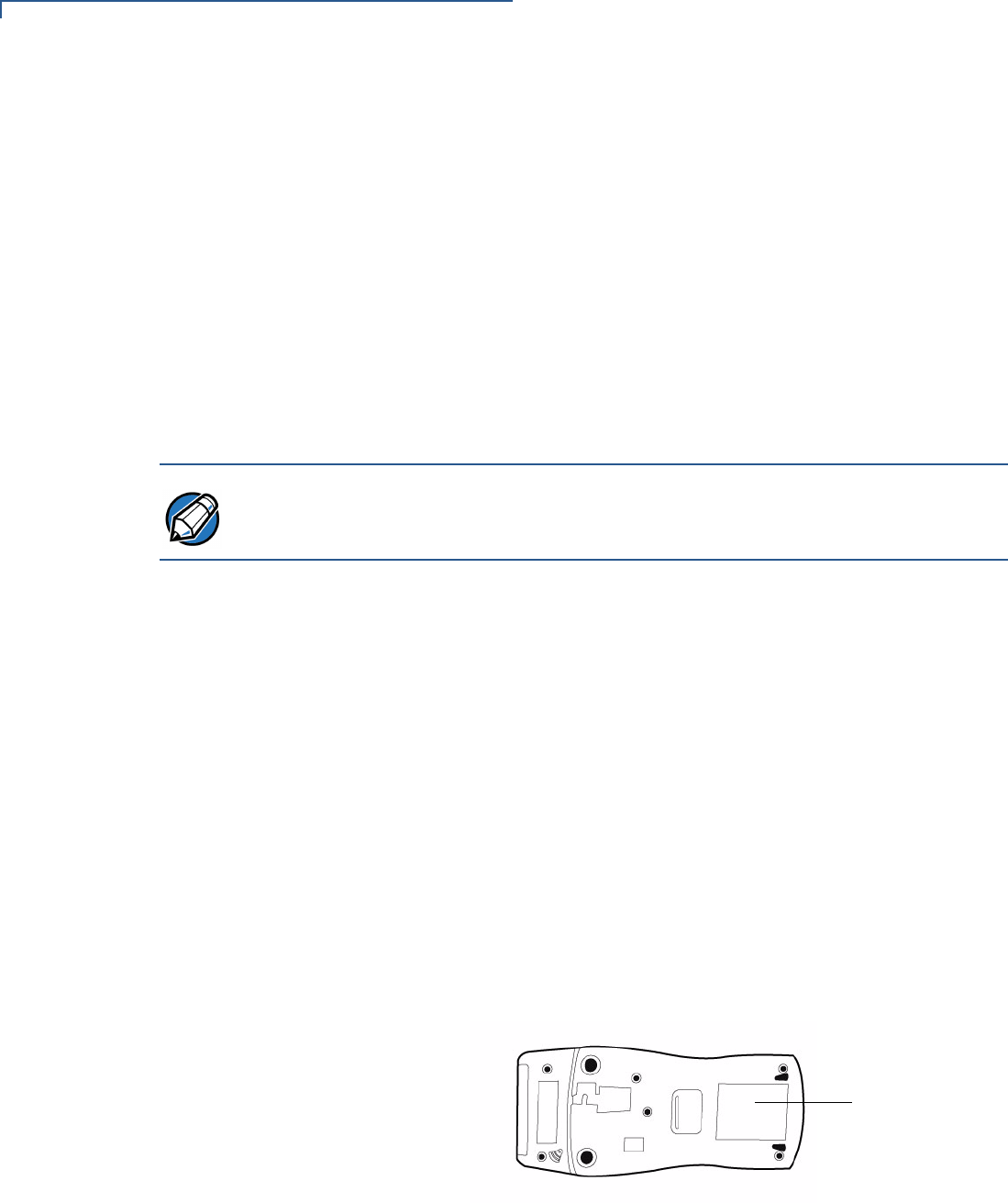
1Gather the following information from the printed labels (see Figure 12) on the
bottom of each PINpad 1000SE CTLS to be returned:
•Product ID, including the model and part number. For example,
“P003-180-02-XXn”
•Serial number (S/N xxx-xxx-xxx)
2Within the United States, call VeriFone toll-free at 1-800-834-9133.
CAUTION Never use thinner, trichloroethylene, or ketone-based solvents – they can
deteriorate plastic or rubber parts.
Because the PINpad 1000SE CTLS can be damaged by liquid, do not spray
cleaners or other solutions directly onto the keypad or display. Always apply the
cleaner to a cloth before cleaning the device.
NOTE International customers, please contact your local VeriFone representative for
assistance with your service, return, or replacement.
SERVICE AND SUPPORT
Service Returns
24 PINPAD 1000SE CTLS INSTALLATION GUIDE
3Select the MRA option from the automated message. The MRA department is
open Monday–Friday, 8 A.M.–7 P.M., EST.
4Give the MRA representative the information gathered in Step 1.
If the list of serial numbers is long, you can fax the list, along with the
information gathered in Step 1, to the MRA department at 1-727-953-4172
(U.S.)
•Please address the fax clearly to the attention of the
“VeriFone MRA Dept.”
•Include a telephone number where you can be reached, as well as your
fax number.
•You will be issued MRA number(s) and the fax will be returned to you.
5Describe the problem(s).
6Provide the shipping address where the repaired or replacement unit must be
returned.
7Keep a record of the following items:
•Assigned MRA number(s).
•VeriFone serial number assigned to the PINpad 1000SE CTLS you are
returning for service or repair (serial numbers are located on the bottom of
the unit (see Figure 12).
•Shipping documentation, such as air bill numbers, used to trace the
shipment.
•Model(s) returned (model numbers are located on the VeriFone label on
the bottom of the PINpad 1000SE CTLS).
Figure 12 Information Label on Unit Bottom
NOTE One MRA number must be issued for each PINpad 1000SE CTLS you return to
VeriFone, even if you are returning several of the same model.
SERIAL
MODEL NUMBER
&

SERVICE AND SUPPORT
Accessories and Documentation
PINPAD 1000SE CTLS INSTALLATION GUIDE 25
Accessories and
Documentation
VeriFone produces accessories and documentation for the PINpad 1000SE CTLS.
When ordering, please refer to the part number in the left column.
•VeriFone Online Store at www.store.verifone.com
•USA – VeriFone Customer Development Center, 1-800-VeriFone (837-4366)
Monday - Friday, 7 A.M. - 5 P.M., MST
•International – Contact your VeriFone representative
Cables Contact your local VeriFone distributor to determine which cable fits your needs.
Power Supply
WCL112012-A RJ11 to RJ11 cable (NURIT)
WCL115001-A RJ11 to RJ45 cable (Vx)
WCL115010-A M-cable (N8400)
WCL115021-A DB9 with power to RJ11 (Shielded)
WCL115013-A RJ11 to USB
CPS11212-1C-R DC power supply (U.S.)
CPS11212-2D-R DC power pack (Europe)
CPS11212-2E-R DC power pack (China)
CPS11212-2F-R DC power pack (UK)

SERVICE AND SUPPORT
Accessories and Documentation
26 PINPAD 1000SE CTLS INSTALLATION GUIDE
PC/AT Interface Kit
Supplementary
Hardware
Cleaning Kit
Documentation
10776-02 4PC plug to DB9 plug (most IBM AT or
compatible computers)
PPL115-028-34-A Stand adapter
PPL115002-A Privacy shield
02746-01 VeriFone Cleaning Kit
•PINpad 1000SE CTLS Certifications and
Regulations
VPN - DOC115EN06-A
•PINpad 1000SE CTLS Quick Installation Guide VPN - DOC115EN05-A
•PINpad 1000SE Reference and Programmers
Guide
VPN - 26803
•PINpad 1000SE Stand Adapter Quick
Installation Guide
VPN - DOC115EN03-A

PINPAD 1000SE CTLS INSTALLATION GUIDE 27
CHAPTER 5
Troubleshooting
Guidelines
This chapter lists typical malfunctions that may occur while operating a
PINpad 1000SE CTLS and the appropriate corrective action. If the problem
persists – even after performing the outlined guidelines, or if the problem is not
described, contact your local VeriFone representative for assistance.
Display Panel
Does Not Work
1Check all the cable connections.
2Check the controller's AC outlet to be sure the outlet is supplying sufficient
power, substitute the controller's power pack with another power pack.
3The controller's application program might not be loaded correctly. Download
the application program and try again.
4Run the display reliability test (option 5), as described in Chapter 12 in the
PINpad 1000SE Reference and Programmers Manual (VPN - 26803).
5If the problem persists, contact your local VeriFone representative.
Keypad Does
Not Respond
1Check the display panel. If there are no characters, or the wrong characters
are displayed, refer to Display Panel Does Not Work.
2Run the keypad reliability test (option 4), as described in Chapter 12 in the
PINpad 1000SE Reference and Programmers Manual (VPN - 26803).
3If the problem persists, contact your local VeriFone representative.
NOTE The PINpad 1000SE CTLS uses a tamper-evident case and contains no user-
serviceable parts. Do not, under any circumstance, attempt to disassemble the
unit. Perform only those adjustments or repairs specified in this guide. For all other
services, contact your local VeriFone service provider. Service conducted by
parties other than authorized VeriFone representatives may void any warranty.