Verifone QX100 Contactless Reader User Manual DOC114EN01C QX100 Installation Manual
VeriFone Inc Contactless Reader DOC114EN01C QX100 Installation Manual
Verifone >
Users Manual Revision 1
QX100
Contactless Reader
Installation Manual
DRAFT
Copyright
© 2007 VeriFone, Inc.
All rights reserved. No part of the contents of this document
may be reproduced or transmitted in any form without the
written permission of VeriFone, Inc.
The information contained in this document is subject to
change without notice. Although VeriFone has attempted to
ensure the accuracy of the contents of this document, this
document may include errors or omissions. The examples are
for illustration only and may not be suited for your purpose.
This document, including without limitation, the examples is
supplied “As-Is.”
Trademark Information
VeriFone, the VeriFone logo, QX, and QX100 are registered
trademarks of VeriFone. Other brand names or trademarks
associated with VeriFone’s products and services are
trademarks of VeriFone, Inc. All other brand names and
trademarks appearing in this manual are the property of their
respective holders.
Catalog Number
DOC114EN01-C
Print Date
June 2007
DRAFT
QX100
Installation Manual iii
Forward
Thank you for purchasing the QX100 Contactless Reader. This
manual includes basic installation instructions in addition to
safety, care, and maintenance instructions.
It is recommended that you store this manual in a safe place for
future reference.
Document Conventions
Note
All graphic images in this manual are for illustrative
purposes only.
Different models of the contactless reader may vary in
appearance according to country of use or particular
customer requirements.
The basic installation procedure is the same for most
units.
The operation of the reader is application-dependent.
Warning Failure to follow specific procedures and practices
may result in personal injury.
Caution Failure to follow specific procedures and practices
may result in damage to the reader or other
equipment.
Note Helpful hints and other important information about
the use of the reader.
DRAFT
DRAFT

QX100
Installation Manual v
Table of Contents
Forward . . . . . . . . . . . . . . . . . . . . . . . . . . . . . . iii
Document Conventions . . . . . . . . . . . . . . . . . . . . . . . . iii
1. Product Regulatory Information. . . . . . . . . . . . . . . .1
2. General Safety Instructions . . . . . . . . . . . . . . . . . .3
3. Specifications . . . . . . . . . . . . . . . . . . . . . . . . . . .4
4. Initial Setup . . . . . . . . . . . . . . . . . . . . . . . . . . . .5
Contents Checklist. . . . . . . . . . . . . . . . . . . . . . . . . . . 5
Selecting a Point-of-Sale Location. . . . . . . . . . . . . . . . . 6
5. Optional Accessories. . . . . . . . . . . . . . . . . . . . . . .7
6. General Features . . . . . . . . . . . . . . . . . . . . . . . . .8
7. Connecting to a POS Terminal or ECR . . . . . . . . . . .10
8. Mounting the Contactless Reader. . . . . . . . . . . . . .15
9. General Care and Maintenance . . . . . . . . . . . . . . .17
Technical Assistance. . . . . . . . . . . . . . . . . . . . . . . . . .17
Cleaning the Contactless Reader. . . . . . . . . . . . . . . . . .17
Shipping the Contactless Reader. . . . . . . . . . . . . . . . . .18
10. Troubleshooting . . . . . . . . . . . . . . . . . . . . . . . . .19
Appendix A: Using the Contactless Reader . . . . . . .21
Positioning the Contactless Reader . . . . . . . . . . . . . . . .21
Startup of the QX100 . . . . . . . . . . . . . . . . . . . . . . . . .22
LED Indicator Status. . . . . . . . . . . . . . . . . . . . . . . . . .22
LED Indication Status One . . . . . . . . . . . . . . . . . . . . . .23
LED Indication Status Two . . . . . . . . . . . . . . . . . . . . . .23
Audio Indication Status . . . . . . . . . . . . . . . . . . . . . . . .23
Contact Information . . . . . . . . . . . . . . . . . . . . . .24
DRAFT
DRAFT

QX100
Installation Manual vii
List of Figures
Figure 4-1 Box Contents. . . . . . . . . . . . . . . . . . . . . . . . . . 5
Figure 5-1 RS-232 Socket—9-Pin D-Type Connector with Power
Connector. . . . . . . . . . . . . . . . . . . . . . . . . . . . 7
Figure 6-1 Front View . . . . . . . . . . . . . . . . . . . . . . . . . . . 8
Figure 6-2 Back View. . . . . . . . . . . . . . . . . . . . . . . . . . . . 9
Figure 7-1 Typical connection to a POS Terminal When Serial Port
has a Power Pin . . . . . . . . . . . . . . . . . . . . . . . .11
Figure 7-2 Typical connection to an ECR When Serial Port has a
Power Pin. . . . . . . . . . . . . . . . . . . . . . . . . . . .11
Figure 7-3 USB Connection to a PC-POS. . . . . . . . . . . . . . . .12
Figure 7-4 Typical D-Type Connection to an ECR or PC-POS with
External Power Source . . . . . . . . . . . . . . . . . . .14
Figure 8-1 Mounting the Contactless Reader . . . . . . . . . . . .16
Figure A-1 Pressing the Positioning Buttons . . . . . . . . . . . . .21
Figure A-2 Positioning the Reader . . . . . . . . . . . . . . . . . . .22
DRAFT
DRAFT

QX100
Installation Manual 1
1. Product Regulatory Information
FCC Compliance Statement
Manufacturer: VeriFone, Inc.
Model: QX100
FCC Part 15 Requirements
This equipment has been tested and found to comply with the
limits for Class B digital device, pursuant to Part 15 of the FCC
Rules. These limits are designed to provide reasonable
protection against harmful interference when the equipment is
installed and operated in a commercial environment.
This equipment generates, uses and can radiate radio
frequency energy and, if not installed and used in accordance
with the instructions, may cause harmful interference to radio
communications. However, there is no guarantee that
interference will not occur in a particular installation.
Operation of this equipment in a residential area is likely to
cause harmful interference in which case the user will be
required to correct the interference at his/her own expense.
If this equipment does cause harmful interference to radio or
television reception, which can be determined by turning the
equipment off and on, the user is encouraged to try to correct
the interference by one or more of the following measures:
• Reorient or relocate the receiving antenna.
• Increase the separation between the equipment and the
receiver.
• Connect the equipment into an outlet on a circuit different
from that to which the receiver is connected.
• Consult your representative or an experienced technician
for help.
Connection of peripherals to this unit requires the use of
grounded, shielded cables to ensure compliance with the
Class B limits.
This device complies with Part 15 of the FCC Rules. Operation
is subject to the following two conditions:
1. This device may not cause harmful interference, and
2. This device must accept any interference received,
including interference that may cause undesired operation.
DRAFT
QX100
2 Installation Manual
In Canada
This digital apparatus does not exceed the Class B limits for
radio noise emissions from digital apparatuses set forth in the
Radio Interference Regulations of the Canadian Department of
Communications.
Cet appareil digital n'émet pas de bruits radioélectriques
dépassant les limites applicables aux appareils de la Classe B,
déterminée par la Réglementation d'Interférence Radio du
Ministère Canadien des Communications.
EU Directives Compliance Statement
This product complies with the requirements of applicable EU
Council Directives.
Note
Changes or modifications to this equipment, not
expressly approved by VeriFone, could void the user's
authority to operate this equipment.
Note
Disposal of this product or any of its components must
be performed in full compliance with all EU and/or
local directives and regulations.
For more information, contact your local VeriFone
representatives or service provider.
DRAFT

QX100
Installation Manual 3
2. General Safety Instructions
When using the QX100 or any associated device, the following
basic safety precautions should always be observed to reduce
the risk of fire, electric shock or personal injury.
•Read and make sure you understand all instructions.
•Follow all warnings and instructions marked on the device
and in this manual.
•Before cleaning, disconnect the device from the power
supply and any device to which the contactless reader is
connected.
•Do not use liquid or aerosol cleaners. Use a damp cloth for
cleaning and/or a soft brush.
•Never spill any liquid on the device.
•Place the device in a stable position on a solid surface or
make sure that the reader is mounted properly. Serious
damage may result if the device falls.
•Do not place objects on the interconnection cable. Install
the device where no one can step on the cable.
•To reduce the risk of electric shock, do not disassemble any
of the equipment or accessories referred to in this manual.
If required, take the equipment to a qualified service
representative. Incorrect reassembly or opening or
removing covers may expose you to dangerous voltages or
other risks.
•Do not overload wall outlets and extension cords as this can
result in the risk of fire or electric shock.
Warning
Failure to observe these instructions may result in
severe personal injury or damage to the QX100 or
other equipment.
Note
These safety instructions are based in general on
those provided by Underwriters Laboratories (UL) Inc.
U.S.A.
DRAFT
QX100
4 Installation Manual
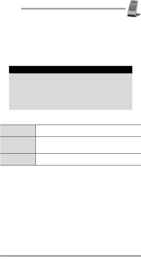
3. Specifications
Specification Details
Power
•Reader when connecting to another device
through an RS-232 connector to an 8-pin
socket (COM):
7-20 V at minimum 250 mA
•External power adapter (safety approved):
Input: 100-240 VAC at 50-60 Hz (0.15 A)
Output: 9 VDC at 0.5 A
Dimensions •Height: 167.8 mm (6.6 in)
•Width: 105.3 mm (4.1 in)
•Depth: 125.9 mm (5 in)
Weight • 270 g (9.52 oz)
Memory • 2MB Flash
Environment
Requirements
•Operational temperature:
0°C to +50°C (+32°F to +122°F)
•Storage temperature:
-20°C to +60°C (-4°F to +140°F)
•Relative humidity:
5 to 95% non-condensing
Note
Specifications are subject to change without notice
following technological improvement of the device and
its components.
DRAFT
QX100
Installation Manual 5
4. Initial Setup
Contents Checklist
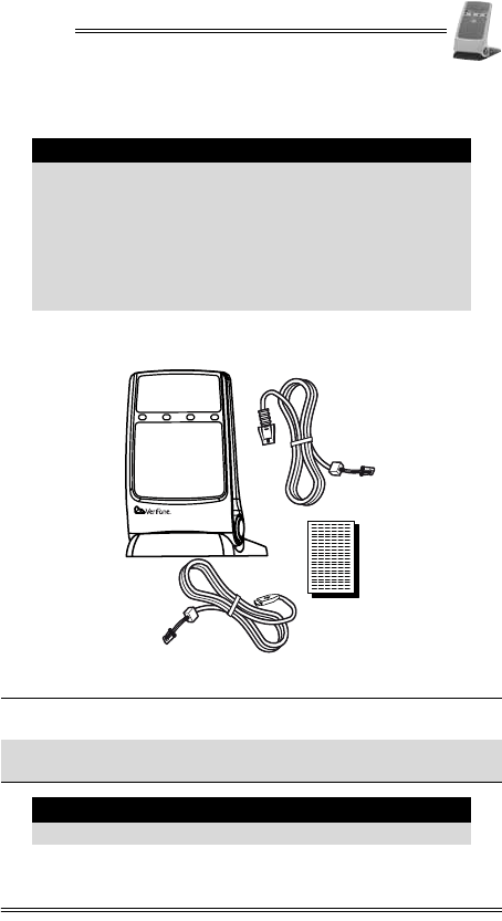
Figure 4-1 Box Contents
Caution
•Carefully inspect the contents of the box for any
damaged or missing components. Do not use a
device that shows any signs of damage.
•VeriFone has taken all measures to provide you
with a complete device. If shipping damage is
evident, file a claim with the shipping company.
Notify your VeriFone representative or service
provider concerning this damage, and if any
components are missing.
1Contactless reader 2RS-232 connector cable
(model dependent)
3Documentation pack 4USB connector cable
(model dependent)
Note
The included cable comes attached to the reader.
1
2
3
4
DRAFT

QX100
6 Installation Manual
Selecting a Point-of-Sale Location
•Place the QX100 on a flat table or countertop close to the
POS terminal or ECR to which it is to be connected, in an
easily accessible place for the cardholder.
•The contactless reader may also be mounted in a fixed
position. See “Mounting the Contactless Reader” for mounting
information.
•Do not cover the QX100.
Note
The contents of the documentation pack may vary
depending on specific customer documentation
requirements.
Warning
Do not locate the reader where it is exposed to the
following:
•Devices that radiate excessive electrical noise or
voltage fluctuations, such as air conditioners, fans,
electric motors, neon signs, or high-frequency
security devices.
•Water containers, such as a sink, a laundry tub or
a pool.
•Areas of excessive moisture, heat, oil, dust or
debris.
•Direct sunlight or objects that radiate heat.
Caution
Overextending the interconnection cable may cause
damage to the contactless reader and to the device to
which it is connected.
DRAFT
QX100
Installation Manual 7
5. Optional Accessories
The QX100 package may include additional optional
accessories packed in its box or boxed separately.
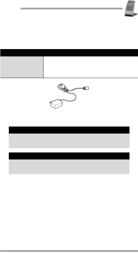
Figure 5-1 RS-232 Socket—9-Pin D-Type Connector with
Power Connector
Accessory Details
RS-232 socket—9-pin
D-type connector
with power
connector
•Connects to the RS-232 connector cable,
enabling the reader to be connected to a
PC-POS as well as an external power.
Caution
Connection of any accessory that is not explicitly
approved by VeriFone may cause damage and thus
void the Limited Warranty of this equipment.
Note
Consult your authorized VeriFone representative or
service provider for information regarding availability
of current or future optional accessories.
DRAFT
QX100
8 Installation Manual
6. General Features
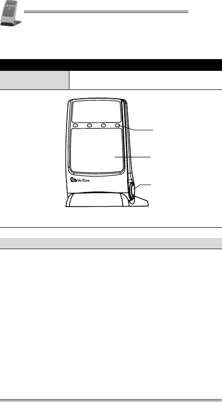
Figure 6-1 Front View
Feature Description
LED Indicators •Colors are model and application
dependent
1LED indicators 2Landing zone
3Positioning button
1
2
3
DRAFT
QX100
Installation Manual 9
Figure 6-2 Back View
1Cable channel
1
DRAFT

QX100
10 Installation Manual
7. Connecting to a POS Terminal or
ECR
The QX100 includes an integrated power/communication cable,
which has either an RS-232 plug or a USB plug at one end for
connection to a POS terminal or ECR (or PC-POS).
There is also an optional RS-232–9-pin D type connection/power
cable, that allows you to plug a contactless reader with the
RS-232 cable into a PC-POS as well as an external power
supply. This can be used with a host device that is not capable
of supplying power through the connector cable.
To connect to a POS terminal or ECR:
1. Disconnect the POS terminal or ECR from its electrical
power supply.
2. Insert the contactless reader RS-232 or USB plug into the
RJ-45 (COM) or USB connector on the POS terminal or ECR.
3. Reconnect the POS terminal, ECR, or PC-POS to its
electrical power supply.
Caution
•Turn off the POS terminal or ECR whenever you
connect or disconnect the contactless reader.
•Do not disconnect the contactless reader when the
POS terminal or ECR is processing data.
Note
Refer to the documentation of the device to which the
reader is to be connected for specific connection
instructions.
DRAFT
QX100
Installation Manual 11
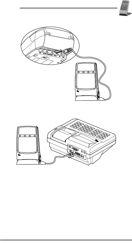
Figure 7-1 Typical connection to a POS Terminal When
Serial Port has a Power Pin
Figure 7-2 Typical connection to an ECR When Serial Port
has a Power Pin
DRAWER
ETHERNET DISPLAY EXT.KB BARCODE
LINE
PHONE
PC PORT
PIN
PAD
POWER
COM1 COM2
RS-232
DRAFT
QX100
12 Installation Manual
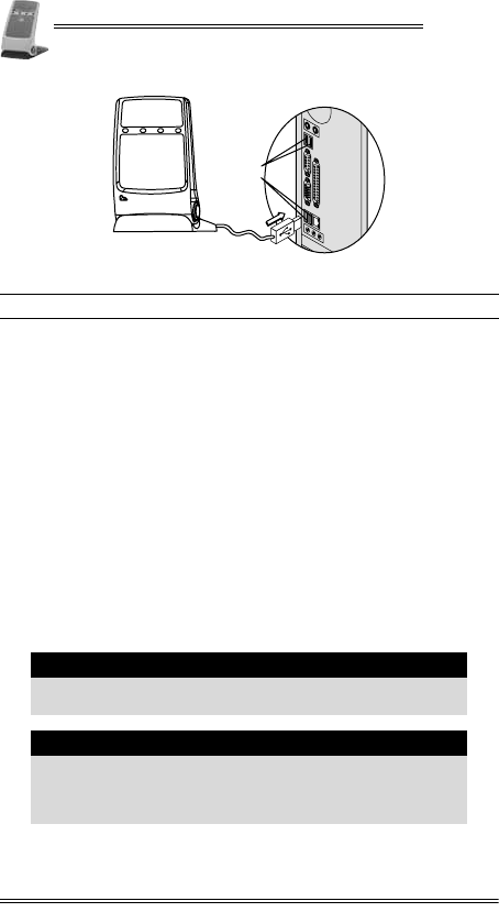
Figure 7-3 USB Connection to a PC-POS
To connect the QX100 to an ECR or PC-POS and to an
external power supply:
1. Disconnect the ECR or PC-POS from its electrical power
supply.
2. Insert the RS-232 cable plug from the contactless reader
(VeriFone supplied) into the RS-232 socket on the
D-type–RS-232 connector cable.
3. Insert the 9-pin D-type serial plug into the connector on the
ECR or PC-POS and tighten the plug’s fastening screws to
secure it in place.
4. Insert the AC/DC power adapter barrel plug into the DC
power connector on the back of the D-type plug.
5. Connect the AC/DC power adapter to an AC electrical
outlet.
6. Reconnect the PC-POS terminal or ECR to its electrical
power supply.
1USB sockets
Warning
Do not plug the AC/DC power adapter into an outdoor
electrical power outlet.
Caution
It is recommended that you install a power surge
arrestor at the power outlet to prevent possible
damage caused by electrical spikes or local lightning
strikes.
1
DRAFT

QX100
Installation Manual 13
Caution
Use a safety-approved Limited Power Supply (LPS)
adapter.
Note
The external power connection is only needed when
there is no power supply via the serial port.
Note
It is recommended to use the VeriFone-supplied AC/DC
power adapter, which provides electrical power to the
QX100 as follows:
•Input (AC): 100-240 V 50/60 Hz (0.15 A maximum)
•Output (DC): 9 VDC at 0.5 A (maximum)
DRAFT
QX100
14 Installation Manual
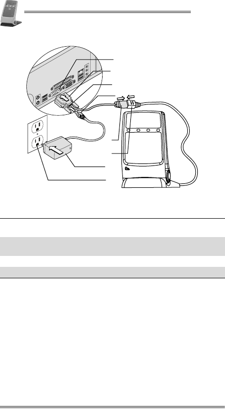
Figure 7-4 Typical D-Type Connection to an ECR or PC-POS
with External Power Source
1D-type serial connector on an
ECR or PC-POS 29-Pin D-type serial plug
3DC power connector 4AC/DC power adapter barrel
plug
5RS-232 connector 6RS-232 plug
7AC/DC power adapter 8AC electrical outlet
5
6
1
2
4
8
3
7
DRAFT
QX100
Installation Manual 15
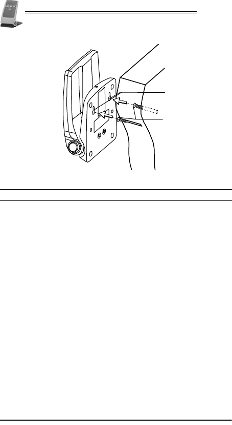
8. Mounting the Contactless Reader
The QX100 is able to lie flat, at a 180° angle, with two key holes
on the bottom panel for mounting the reader on a wall.
To mount the QX100:
1. Drill two holes in the wall for screws, with a 5.5 cm
(2.165 in) between them, according to the drilling pattern.
2. Insert wall inserts with screws.
3. Adjust the mounting screw heads until they are firmly in
place.
4. Take the reader and face the bottom of the base towards
the wall, with the narrow part of the key hole facing
upwards.
5. Push the base, so that the mounting holes at the bottom of
the base are around the screw heads.
Note
When mounting the contactless reader, it must be
close enough to the POS terminal or ECR, for the
connecting cables, and in an easily accessible location
for the customer.
Note
The recommended screws for mounting the QX100 are
flat head screws with a thread diameter of
approximately 4 mm (0.157 in) and head diameter of
approximately 8 mm (0.315 in).
Note
The manual includes a drilling pattern in the back, for
your convenience.
DRAFT
QX100
16 Installation Manual
Figure 8-1 Mounting the Contactless Reader
6. Slide the base down, so that the screws are supporting the
base.
1Mounting key holes 2Mounting screws
1
2
DRAFT

QX100
Installation Manual 17
9. General Care and Maintenance
The QX100 has been designed to give you long and trouble-free
service with minimal operator care.
To maintain proper functioning of the reader:
•Keep the reader in the cleanest possible working and
storage environment.
•Protect the reader from direct sunlight, extreme heat, damp
and dust.
•Do not open the AC/DC Power Adapter.
•Do not shake or drop the reader.
•Do not attempt to open the reader.
Technical Assistance
Contact your VeriFone representative or service provider for
technical assistance and ordering information regarding
specific components.
Cleaning the Contactless Reader
To clean the contactless reader:
•Gently wipe off dirt from the reader with a soft, damp,
lint-free cloth.
•A very mild dishwashing detergent can be used to dampen
the cloth.
•Alcohol or alcohol-based cleansers may also be used for
stains that are more difficult.
•When necessary, gently wipe the display with a soft cloth or
eyeglass lens wiper.
Caution
•Never use abrasive compounds or solvents,
thinners, benzene, or synthetic cleansers as they
may distort or damage the plastic and critical
parts.
DRAFT

QX100
18 Installation Manual
Shipping the Contactless Reader
In exceptional circumstances, you may be required to ship your
reader to a servicing facility.
To ship the QX100:
1. Carefully pack the reader, preferably in the original box.
2. Send the package prepaid and adequately insured.
Note
•Notify your VeriFone representative or service
provider before shipping the contactless reader. In
some cases, you may be required to attach a letter
to the package detailing the problem and
including product information such as the serial
number and the date of purchase.
•Shipment must be to an authorized dealer or
service center only. Contact your VeriFone
representative for the correct address.
DRAFT
QX100
Installation Manual 19
10. Troubleshooting
The QX100 has been designed for trouble-free operation,
though minor problems may occur during installation and use.
This section briefly describes how to troubleshoot some
possible common problems that may arise during the normal
operation of the contactless reader.
Before requesting service for the reader, read this section to
find a possible remedy for the problem. If you are still unable to
solve the problem, contact a service representative.
Do not try to solve the problem by opening the reader yourself.
The reader appears to have no power
1. Check that the buzzer on the QX100 beeps when you turn on the
reader.
2. When using an RJ-45 molten cable (RS-232):
•Make sure that the device which supplies the QX100 with
power is turned on.
•Make sure that the RJ-45 connector is fully plugged into the
socket.
3. When using an RS-232–9-pin D type connection/power cable and
AC/DC adapter:
•Make sure that the AC adapter is fully plugged into the AC
main power outlet.
•Make sure that the AC adapter’s barrel connector is fully
connected with the PWR connector.
•Try plugging the AC adapter into another AC power outlet.
4. If the problem persists, contact a VeriFone certified service
representative.
DRAFT
QX100
20 Installation Manual
The LEDs are not lighting up
1. Check that the buzzer on the QX100 beeps when you turn on the
reader.
•If NO, act according to “The reader appears to have no
power”.
•If YES, hold a PICC card up to the landing zone on the reader.
If some of the LEDs light up, the ones that do not are burnt
out. To change a LED, contact a VeriFone certified
representative.
2. If the problem persists, contact a VeriFone certified service
representative.
DRAFT
QX100
Installation Manual 21
Appendix A: Using the
Contactless Reader
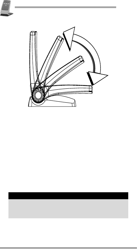
Positioning the Contactless Reader
The contactless reader can be moved to four positions:
•Laying flat
•30°
•60°
•90°
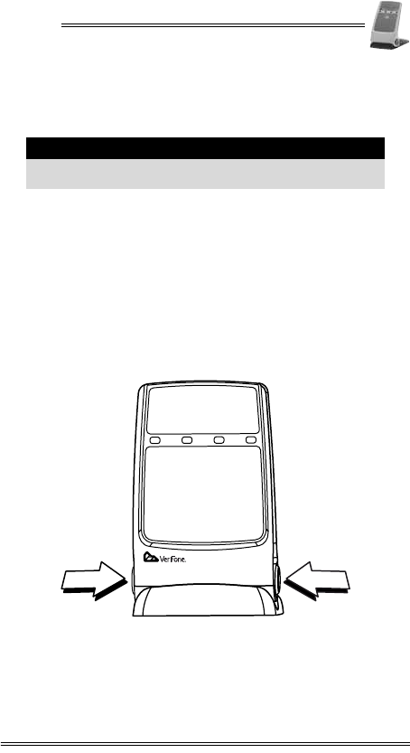
To position your reader:
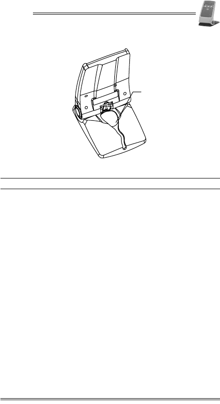
1. With your thumb and middle finger, press the buttons on
both sides of the reader.
Figure A-1 Pressing the Positioning Buttons
2. While holding down the positioning buttons, with your
other hand, hold the top of the reader, pushing or pulling to
the desired position.
Note
The card must be within 4 cm (1.57 in) of the landing
zone for the QX100 to read the card.
DRAFT
QX100
22 Installation Manual
Figure A-2 Positioning the Reader
Startup of the QX100
The QX100 starts up automatically when:
•The reader is plugged into a terminal with a power source,
and the terminal is first powered-up.
•The reader is first plugged into an electrical outlet.
To recognize the QX100 is powered-up:
1. The reader’s lights being activated, blinking from left to
right, sequentially.
2. The lights are then followed by a short audio indication.
3. The LEDs go to their “ready for the next transaction” state.
LED Indicator Status
There are two common color schemes for the LED indicators.
Note
The LED indicator colors are credit card application
dependent. For information on what cards are
accepted and which application is being used, contact
your local VeriFone service provider.
DRAFT
QX100
Installation Manual 23
LED Indication Status One
LED Indication Status Two
All four LEDs are green:
•When ready for the next transaction, there is a single green
indicator light.
•While the transaction is being processed, the LED
indicators light up from left to right.
Audio Indication Status
There are audio indications to let the cardholder know the
status of the reading of his/her card.
•The first beep is to indicate the reading of the card.
•There are three sequential beeps, as the remainder LEDs
light up.
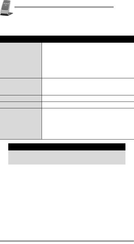
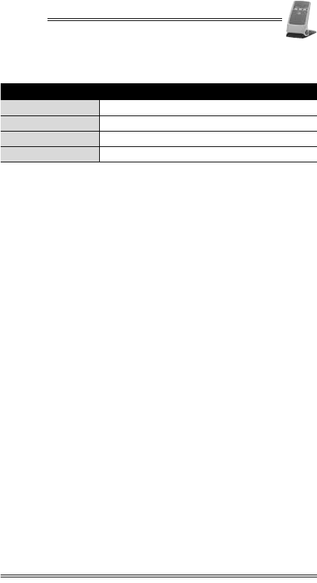
Indicator Payment Status
Blue Ready for next transaction
Yellow Processing the transaction
Green Transaction accepted
Red Transaction failed
DRAFT

QX100
24 Installation Manual
Contact Information
VeriFone, Inc.
2099 Gateway Place, Suite 600
San Jose, CA, 95110 USA
Tel: +1-800-VeriFone (837-4366)
www.verifone.com
DRAFT