Verifone VX610EVDO POINT OF SALES TERMINAL User Manual 23216 book
VeriFone Inc POINT OF SALES TERMINAL 23216 book
Verifone >
Contents
- 1. USERS MANUAL 1
- 2. USERS MANUAL 2
USERS MANUAL 1

VeriFone Part Number 23216, Revision C
Omni 5xxx and Vx5xx/Vx610
Installation Guide

All rights reserved. No part of the contents of this document may be reproduced or transmitted in any form without the written
permission of VeriFone, Inc.
The information contained in this document is subject to change without notice. Although VeriFone has attempted to ensure the
accuracy of the contents of this document, this document may include errors or omissions. The examples and sample programs are
for illustration only and may not be suited for your purpose. You should verify the applicability of any example or sample program
before placing the software into productive use. This document, including without limitation the examples and software programs, is
supplied “As-Is.”
VeriFone, Inc.
2099 Gateway Place, Suite 600
San Jose, CA, 95110 USA
www.verifone.com
VeriFone Part Number 23216, Revision C
Omni 5xxx and Vx5xx/Vx610 Installation Guide
© 2006 VeriFone, Inc.
VeriFone, the VeriFone logo, Omni, VeriCentre, Verix, and ZonTalk are registered trademarks of VeriFone. Other brand names or
trademarks associated with VeriFone’s products and services are trademarks of VeriFone, Inc.
All other brand names and trademarks appearing in this manual are the property of their respective holders.
Comments? Please e-mail all comments on this document to your local VeriFone Support Team.
WARNING
Do not dispose of the Vx610 Li-ion smart battery in a fire. Li-ion batteries must be recycled or
disposed of properly. Do not dispose of Li-ion batteries in municipal waste sites.

OMNI 5XXX AND VX5XX/VX610 INSTALLATION GUIDE 3
CONTENTS
PREFACE . . . . . . . . . . . . . . . . . . . . . . . . . . . . . . . . . . . . . . . 5
Audience. . . . . . . . . . . . . . . . . . . . . . . . . . . . . . . . . . . . . . . . . . . . . . . . . . . . . . . . 5
Organization . . . . . . . . . . . . . . . . . . . . . . . . . . . . . . . . . . . . . . . . . . . . . . . . . . . . . 5
Related Documentation . . . . . . . . . . . . . . . . . . . . . . . . . . . . . . . . . . . . . . . . . . . . 6
Conventions and Acronyms . . . . . . . . . . . . . . . . . . . . . . . . . . . . . . . . . . . . . . . . . 7
Document Conventions. . . . . . . . . . . . . . . . . . . . . . . . . . . . . . . . . . . . . . . . . . 7
Acronym Definitions . . . . . . . . . . . . . . . . . . . . . . . . . . . . . . . . . . . . . . . . . . . . 7
CHAPTER 1
Terminal Overview Features and Benefits . . . . . . . . . . . . . . . . . . . . . . . . . . . . . . . . . . . . . . . . . . . . 10
Exceptional Ease of Use. . . . . . . . . . . . . . . . . . . . . . . . . . . . . . . . . . . . . . . . 10
Countertop Performance in a “Hand-Over” Design. . . . . . . . . . . . . . . . . . . . 11
True Multi-Application Capability . . . . . . . . . . . . . . . . . . . . . . . . . . . . . . . . . 11
Wireless Connectivity . . . . . . . . . . . . . . . . . . . . . . . . . . . . . . . . . . . . . . . . . . 11
CHAPTER 2
Terminal Setup Selecting Terminal Location . . . . . . . . . . . . . . . . . . . . . . . . . . . . . . . . . . . . . . . . 13
Ease of Use . . . . . . . . . . . . . . . . . . . . . . . . . . . . . . . . . . . . . . . . . . . . . . . . . 13
Environmental Factors . . . . . . . . . . . . . . . . . . . . . . . . . . . . . . . . . . . . . . . . . 13
Electrical Considerations . . . . . . . . . . . . . . . . . . . . . . . . . . . . . . . . . . . . . . . 14
Unpacking the Shipping Carton . . . . . . . . . . . . . . . . . . . . . . . . . . . . . . . . . . . . . 14
Examining Terminal Features. . . . . . . . . . . . . . . . . . . . . . . . . . . . . . . . . . . . . . . 15
Front Panel . . . . . . . . . . . . . . . . . . . . . . . . . . . . . . . . . . . . . . . . . . . . . . . . . . 15
Connection Ports . . . . . . . . . . . . . . . . . . . . . . . . . . . . . . . . . . . . . . . . . . . . . 16
Establishing Telephone Line Connections . . . . . . . . . . . . . . . . . . . . . . . . . . . . . 18
Installing the Paper Roll in the Printer . . . . . . . . . . . . . . . . . . . . . . . . . . . . . . . . 19
Installing/Replacing MSAM Cards . . . . . . . . . . . . . . . . . . . . . . . . . . . . . . . . . . . 22
Connecting Optional Device(s). . . . . . . . . . . . . . . . . . . . . . . . . . . . . . . . . . . . . . 24
Vx510 and Vx570 Optional Device Connections . . . . . . . . . . . . . . . . . . . . . . 24
Vx610 Optional Device Connections. . . . . . . . . . . . . . . . . . . . . . . . . . . . . . . 26
External Printers Supported . . . . . . . . . . . . . . . . . . . . . . . . . . . . . . . . . . . . . 27
Connecting the Terminal Power Pack . . . . . . . . . . . . . . . . . . . . . . . . . . . . . . . . 28
Vx610 Battery Behavior (No Power Cord) . . . . . . . . . . . . . . . . . . . . . . . . . . . . . 30
Manual Startup . . . . . . . . . . . . . . . . . . . . . . . . . . . . . . . . . . . . . . . . . . . . . . . 30
Manual Shutdown . . . . . . . . . . . . . . . . . . . . . . . . . . . . . . . . . . . . . . . . . . . . . 30
Installing the Privacy Shield . . . . . . . . . . . . . . . . . . . . . . . . . . . . . . . . . . . . . . . . 31
Vx510/Vx610 Privacy Shield . . . . . . . . . . . . . . . . . . . . . . . . . . . . . . . . . . . . . 31
Vx570 Privacy Shield . . . . . . . . . . . . . . . . . . . . . . . . . . . . . . . . . . . . . . . . . . 32
Installing the Vx610 Smart Battery . . . . . . . . . . . . . . . . . . . . . . . . . . . . . . . . . . . 33
Installation. . . . . . . . . . . . . . . . . . . . . . . . . . . . . . . . . . . . . . . . . . . . . . . . . . . 33
Removal . . . . . . . . . . . . . . . . . . . . . . . . . . . . . . . . . . . . . . . . . . . . . . . . . . . . 34
Charging . . . . . . . . . . . . . . . . . . . . . . . . . . . . . . . . . . . . . . . . . . . . . . . . . . . . 34
Battery Life . . . . . . . . . . . . . . . . . . . . . . . . . . . . . . . . . . . . . . . . . . . . . . . . . . 34
Using the Vx610 Spare Battery Charger. . . . . . . . . . . . . . . . . . . . . . . . . . . . . . . 35
Using the Vx610 Power Cradle. . . . . . . . . . . . . . . . . . . . . . . . . . . . . . . . . . . . . . 36

CONTENTS
4OMNI 5XXX AND VX5XX/VX610 INSTALLATION GUIDE
Install/Replace SIM Card
(GSM/GPRS Models) . . . . . . . . . . . . . . . . . . . . . . . . . . . . . . . . . . . . . . . . . . . . . 37
Connecting the Vx610 External Antenna . . . . . . . . . . . . . . . . . . . . . . . . . . . . . . 40
Installation. . . . . . . . . . . . . . . . . . . . . . . . . . . . . . . . . . . . . . . . . . . . . . . . . . . 40
Orientation . . . . . . . . . . . . . . . . . . . . . . . . . . . . . . . . . . . . . . . . . . . . . . . . . . 41
Replacing the Antenna . . . . . . . . . . . . . . . . . . . . . . . . . . . . . . . . . . . . . . . . . 41
Conducting Wireless Transactions . . . . . . . . . . . . . . . . . . . . . . . . . . . . . . . . . . . 42
Using the Smart Card Reader . . . . . . . . . . . . . . . . . . . . . . . . . . . . . . . . . . . . . . 42
Using the Magnetic Card Reader . . . . . . . . . . . . . . . . . . . . . . . . . . . . . . . . . . . . 42
CHAPTER 3
Specifications Power . . . . . . . . . . . . . . . . . . . . . . . . . . . . . . . . . . . . . . . . . . . . . . . . . . . . . . . . . 45
DC Power Pack . . . . . . . . . . . . . . . . . . . . . . . . . . . . . . . . . . . . . . . . . . . . . . . . . 45
Temperature . . . . . . . . . . . . . . . . . . . . . . . . . . . . . . . . . . . . . . . . . . . . . . . . . . . . 45
External Dimensions. . . . . . . . . . . . . . . . . . . . . . . . . . . . . . . . . . . . . . . . . . . . . . 45
SAR Compliance . . . . . . . . . . . . . . . . . . . . . . . . . . . . . . . . . . . . . . . . . . . . . . . . 46
CDMA . . . . . . . . . . . . . . . . . . . . . . . . . . . . . . . . . . . . . . . . . . . . . . . . . . . . . . 46
GSM/GPRS. . . . . . . . . . . . . . . . . . . . . . . . . . . . . . . . . . . . . . . . . . . . . . . . . . 46
CHAPTER 4
Maintenance Clean the Terminal . . . . . . . . . . . . . . . . . . . . . . . . . . . . . . . . . . . . . . . . . . . . . . . 47
Terminal Contacts . . . . . . . . . . . . . . . . . . . . . . . . . . . . . . . . . . . . . . . . . . . . . . . 47
Smart Card Reader . . . . . . . . . . . . . . . . . . . . . . . . . . . . . . . . . . . . . . . . . . . . . . 47
CHAPTER 5
VeriFone Service
and Support
Return a Terminal or Smart Battery for Service . . . . . . . . . . . . . . . . . . . . . . . . . 49
Accessories and Documentation . . . . . . . . . . . . . . . . . . . . . . . . . . . . . . . . . . . . 50
Power Pack. . . . . . . . . . . . . . . . . . . . . . . . . . . . . . . . . . . . . . . . . . . . . . . . . . 50
Thermal Printer Paper. . . . . . . . . . . . . . . . . . . . . . . . . . . . . . . . . . . . . . . . . . 50
VeriFone Cleaning Kit . . . . . . . . . . . . . . . . . . . . . . . . . . . . . . . . . . . . . . . . . . 51
Telephone Line Cord . . . . . . . . . . . . . . . . . . . . . . . . . . . . . . . . . . . . . . . . . . 51
Swivel Stand . . . . . . . . . . . . . . . . . . . . . . . . . . . . . . . . . . . . . . . . . . . . . . . . . 51
Documentation . . . . . . . . . . . . . . . . . . . . . . . . . . . . . . . . . . . . . . . . . . . . . . . 51
CHAPTER 6
Troubleshooting
Guidelines
Blank Display . . . . . . . . . . . . . . . . . . . . . . . . . . . . . . . . . . . . . . . . . . . . . . . . . . . 53
Terminal Does Not Dial Out . . . . . . . . . . . . . . . . . . . . . . . . . . . . . . . . . . . . . . . . 53
Printer Paper Jam. . . . . . . . . . . . . . . . . . . . . . . . . . . . . . . . . . . . . . . . . . . . . . . . 54
Keypad Does Not Respond . . . . . . . . . . . . . . . . . . . . . . . . . . . . . . . . . . . . . . . . 54
Peripheral Device Does Not Work . . . . . . . . . . . . . . . . . . . . . . . . . . . . . . . . . . . 54
Transactions Fail To Process . . . . . . . . . . . . . . . . . . . . . . . . . . . . . . . . . . . . . . . 54
Printer Does Not Print. . . . . . . . . . . . . . . . . . . . . . . . . . . . . . . . . . . . . . . . . . . . . 55
Terminal Display Does not Show Correct/Readable Information . . . . . . . . . . . . 56
Vx610 Terminal Does Not Start . . . . . . . . . . . . . . . . . . . . . . . . . . . . . . . . . . . . . 56
Vx610 Smart Battery Will Not Charge. . . . . . . . . . . . . . . . . . . . . . . . . . . . . . . . . 56
Printer Does Not Print. . . . . . . . . . . . . . . . . . . . . . . . . . . . . . . . . . . . . . . . . . . . . 56
INDEX . . . . . . . . . . . . . . . . . . . . . . . . . . . . . . . . . . . . . . . . .57

OMNI 5XXX AND VX5XX/VX610 INSTALLATION GUIDE 5
PREFACE
This guide is your primary source of information for setting up and installing the
Vx5xx/Vx610 terminal.
Audience
This guide is useful for anyone installing and configuring a Vx5xx/Vx610 terminal.
Basic descriptions of the terminal features are also provided.
Organization
This guide is organized as follows:
Chapter 1, Terminal Overview. Provides an overview of the Vx5xx/Vx610 series of
terminals.
Chapter 2, Terminal Setup. Explains how to set up and install the Vx5xx/Vx610
terminal. It tells you how to select a location, establish power and telephone line
connections, and how to configure optional peripheral devices.
Chapter 3, Specifications. Discusses power requirements and dimensions of the
Vx5xx/Vx610 terminal.
Chapter 4, Maintenance. Explains how to maintain your Vx5xx/Vx610 terminal.
Chapter 5, VeriFone Service and Support. Provides information on contacting
your local VeriFone representative or service provider, and information on how to
order accessories or documentation from VeriFone.
Chapter 6, Troubleshooting Guidelines. Provides troubleshooting guidelines,
should you encounter a problem in terminal installation and configuration.
NOTE In this document, Vx5xx/Vx610 refers to the series of VeriFone terminals,
including the Vx510 (Omni 5100/5150), Vx570 (Omni 5700/5750), and Vx610
(Omni 5600).

PREFACE
Related Documentation
6OMNI 5XXX AND VX5XX/VX610 INSTALLATION GUIDE
Related
Documentation
To learn more about the Vx5xx/Vx610 series of terminals, refer to the following set
of documents:
For Vx510:
For Vx570:
For Vx610:
For Vx510 and Vx610:
Omni 5100/5150 and Vx510, Omni 3730 Certifications
and Regulations
VPN 23218
Omni 5100/5150 and Vx510 Quick Installation Guide VPN 23219
Omni 5100/5150 and Vx510 with Ethernet Quick
Installation Guide
VPN 23268
Omni 37xx/5xxx and Vx5xx Stacker Quick Installation
Guide
VPN 23784
Omni 51xx and Vx5xx Swivel Stand Quick Installation
Guide
VPN 23043
Omni 5700/5750 and Vx570 Certifications and
Regulations
VPN 23646
Omni 57xx and Vx570 Quick Installation Guide VPN 23759
Omni 57xx and Vx570 Large Paper Door Quick
Installation Guide
VPN 24126
Omni 57xx and Vx570 Privacy Shield Quick
Installation Guide
VPN 24134
Omni 56xx and Vx610 Carrying Case Quick
Installation Guide
VPN 23640
Omni 56xx and Vx610 Attachable Strap/Handstrap
Quick Installation Guide
VPN 23641
Omni 56xx and Vx610 Quick Installation Guide VPN 23643
Omni 56xx and Vx610 Certifications and Regulations VPN 23644
Omni 56xx and Vx610 Spare Battery Charger Quick
Installation Guide
VPN 23645
Omni 56xx and Vx610 Power Cradle Quick Installation
Guide
VPN 24125
Omni 5xxx and Vx510/Vx610 Privacy Shield Quick
Installation Guide
VPN 23642

PREFACE
Conventions and Acronyms
OMNI 5XXX AND VX5XX/VX610 INSTALLATION GUIDE 7
Conventions and
Acronyms
This section describes the conventions and acronyms used in this guide.
Document
Conventions
Various conventions are used to help you quickly identify special formatting. Table
1 describes these conventions and provides examples of their use.
Acronym Definitions
Various acronyms are used in place of the full definition. Table 2 presents
acronyms and their definitions.
Table 1 Document Conventions
Convention
Blue Text in blue indicates terms
that are cross referenced.
See Conventions and Acronyms.
Italics Italic typeface indicates
book titles or emphasis.
You must install a roll of thermal-
sensitive paper in the printer.
Courier The courier type face is
used while specifying
onscreen text, such as text
that you would enter at a
command prompt, or to
provide an URL.
http://www.verifone.com
The pencil icon is used to
highlight important
information.
RS-232-type devices do not work with
the PINpad port.
The caution symbol
indicates possible hardware
or software failure, or loss
of data.
The terminal is not waterproof or
dustproof, and is intended for indoor
use only.
The lighting symbol is used
as a warning when bodily
injury might occur.
Due to risk of shock do not use the
terminal near water.
NOTE
CAUTION
WARNING
Table 2 Acronym Definitions
Acronym Definitions
AC Alternating Current
ATM Automated Teller Machine
CDMA Code Division Multiple Access
CR Check Reader
EMV Europay MasterCard and VISA
GPRS General Packet Radio Service
GSM Global System for Mobile Communication
ITP Internal Thermal Printer
LCD Liquid Crystal Display

PREFACE
Conventions and Acronyms
8OMNI 5XXX AND VX5XX/VX610 INSTALLATION GUIDE
LED Light Emitting Diode
MRA Merchandise Return Authorization
MSAM Micromodule-Size Security Access Module
PED PIN-Entry Devices
PIN Personal Identification Number
RJ45 Registered Jack 45
RS-232 Recommended Standard 232
SAM Security Access Module
VPN VeriFone Part Number
Wi-Fi Wireless Fidelity
Table 2 Acronym Definitions (continued)
Acronym Definitions

OMNI 5XXX AND VX5XX/VX610 INSTALLATION GUIDE 9
CHAPTER 1
Terminal Overview
This chapter provides a brief description of the Vx5xx/Vx610 series of terminals.
The Vx5xx/Vx610 terminal series represents the shape of things to come in e-
payment. These terminals are members of a broad product family that will provide
a clear migration path into the future for current users of Omni countertop and
portable terminals.
•The Vx510 is a high performance countertop terminal with fixed enhanced
communication options. The Vx510 (also referred to as Omni 5100/5150) is
the entry-point countertop terminal.
•The Vx610 represents a new generation of wireless terminals. The pioneering
Vx610 (also known as Omni 5600) features the same sleek, compact design of
the Vx510, but in a portable, battery-powered form factor that uses wireless
technologies, including Wi-Fi, CDMA and GSM/GPRS.
•The Vx570 (also known as Omni 5700/5750) is a high performance countertop
terminals with modular communication options, enhanced display, expanded
memory options, and a USB peripheral port.
Vx510 and Vx610 terminals use a bold ergonomic design that is sleek and stylish,
offering countertop power and 32-bit performance in an integrated terminal that
can be handed to the consumer for input. The Vx570 design continues the
success of the Omni 37xx design.
The Vx510 and Vx610 serve as the entry point to VeriFone’s acclaimed multi-
application platform—with the capability to securely support payment and value-
added applications on a single terminal—while the Vx570 is perfect for those
customers who need more.
TERMINAL OVERVIEW
Features and Benefits
10 OMNI 5XXX AND VX5XX/VX610 INSTALLATION GUIDE
Features and
Benefits
Vx5xx/Vx610 terminals provide the right combination of features and functions.
This includes a triple-track magnetic-stripe card reader, smart card reader,
integrated PINpad, and a quiet yet fast internal thermal printer (ITP).
Exceptional Ease of
Use
•The bold design is sleek, stylish, and lightweight for conveniently handing the
terminal to the consumer for PIN entry or other input.
•An intuitive ATM-style interface, a large 8-line x 21-character backlit display
with split-screen capabilities, large keys, and extra-size menu prompts simplify
training and reduce help desk calls.
•The integrated high-speed thermal printer simplifies paper loading and
virtually eliminates paper jams.
•The triple-track, high-coercivity card reader handles most magnetic stripe
cards.
NOTE VeriFone ships variants of the Vx5xx/Vx610 terminals for different markets. Your
terminal may have a different configuration. The following devices may or may not
be present: a smart card reader, or zero or three MSAM cardholders.
Features at a Glance
•Delivers power and usability in a
convenient “hand-over” design.
•Securely supports and runs payment
and value-added applications.
•Multi-application operating
environment.
•Offers unsurpassed performance on
EMV smart card transactions.
•32-bit processing and multi-tasking
capabilities.
•Security architecture meets
specifications for PED and
sophisticated file authentication.

TERMINAL OVERVIEW
Features and Benefits
OMNI 5XXX AND VX5XX/VX610 INSTALLATION GUIDE 11
Countertop
Performance in a
“Hand-Over” Design
•The 32-bit processing and multi-tasking capabilities make short work of
payment, payment-related, and value-added applications.
•The Vx5xx/Vx610 series of terminals has exceptional display and printer
graphics-handling capabilities that quickly render logos, graphical fonts, and
character-based languages.
•The VeriCentre Appliance Management Suite employs advanced file
compression to streamline simultaneous downloads of application software to
hundreds of terminals.
•The integrated PINpad offers added convenience to handle PIN-based
applications.
•The Vx5xx/Vx610 series of terminals ensures uncompromising reliability from
VeriFone, the worldwide leader in e-payment.
True Multi-
Application
Capability
•Vx510 and Vx610 terminals offer 3 MB or 6 MB of memory and the dynamic
memory allocation of the Verix V OS, support two or three typical-sized
applications on a single terminal. The Vx570 offers 6 MB and 12 MB memory
options.
•The primary smart card reader and the MSAMs safeguard sensitive financial
data and support multiple smart card schemes.
•The Vx5xx/Vx610 series of terminals and SoftPay EMV software have
received EMV Level 1 and Level 2 Type approval for smart card solutions. The
Verix EMV Library provides efficient development of other EMV-compliant
applications.
•The VeriShield security architecture meets published specifications for PED
and provides sophisticated file authentication to prevent execution of
unauthorized software on Vx5xx/Vx610 terminals.
Wireless
Connectivity
•With the Vx610 wireless terminals, the point of payment can be almost
anywhere. Customers are not tied to a fixed location.
•“Always on” wireless connection is made using the latest wireless
technologies, including GSM/GPRS, CDMA and Wi-Fi. The Vx570 also offers
an additional ISDN (Integrated Services Digital Network) communications
option.

TERMINAL OVERVIEW
Features and Benefits
12 OMNI 5XXX AND VX5XX/VX610 INSTALLATION GUIDE

OMNI 5XXX AND VX5XX/VX610 INSTALLATION GUIDE 13
CHAPTER 2
Terminal Setup
This chapter describes the terminal setup procedure. You will learn about:
•Selecting Terminal Location.
•Unpacking the Shipping Carton.
•Examining Terminal Features.
•Establishing Telephone Line Connections.
•Installing the Paper Roll in the Printer.
•Installing/Replacing MSAM Cards.
•Connecting Optional Device(s).
•Connecting the Terminal Power Pack.
•Installing the Privacy Shield.
•Installing the Vx610 Smart Battery.
•Using the Vx610 Spare Battery Charger.
•Using the Vx610 Power Cradle.
•Installing/Replacing the SIM Card (GSM/GPRS Models).
•Connecting the Vx610 External Antenna.
•Conducting Wireless Transactions.
•Using the Smart Card Reader.
•Using the Magnetic Card Reader.
Selecting
Terminal
Location
Use the following guidelines when selecting a location for your Vx5xx/Vx610
terminal.
Ease of Use
•Select a location convenient for both merchant and cardholder.
•Select a flat support surface, such as a countertop or table.
•Select a location near a power outlet and a telephone/modem line connection.
For safety, do not string the power cord in a walkway or place it across a
walkway on the floor.
Environmental
Factors
•Do not use the terminal where there is high heat, dust, humidity, moisture, or
caustic chemicals or oils.

TERMINAL SETUP
Unpacking the Shipping Carton
14 OMNI 5XXX AND VX5XX/VX610 INSTALLATION GUIDE
•Keep the terminal away from direct sunlight and anything that radiates heat,
such as a stove or motor.
•Do not use the terminal outdoors.
Electrical
Considerations
•Avoid using this product during electrical storms.
•Avoid locations near electrical appliances or other devices that cause
excessive voltage fluctuations or emit electrical noise (for example, air
conditioners, electric motors, neon signs, high-frequency or magnetic security
devices, or computer equipment).
•Do not use the terminal near water or in moist conditions.
Unpacking the
Shipping Carton
Open the shipping carton and carefully inspect its contents for possible tampering
or shipping damage. The Vx5xx/Vx610 terminal is a secure product and any
tampering may cause the device to cease to function properly.
To unpack the
Shipping Carton
1Remove and inspect the following items:
•Terminal
•Power pack
•Telephone line cord
•Power cord
•Battery pack (for Vx610 only)
•Antenna (for Vx610 only, if shipped loose)
•Paper roll
2Remove all plastic wrapping from the terminal and other components.
3Remove the clear protective film from the LCD screen.
4Save the shipping carton and packing material for future repacking or moving
the terminal.
CAUTION The terminal is not waterproof or dustproof, and is intended for indoor use only.
Any damage to the unit from exposure to rain or dust may void any warranty.
CAUTION Do not use a terminal that has been damaged or tampered with. The
Vx5xx/Vx610 terminal comes equipped with tamper-evident labels. If a label or
component appears damaged, please notify the shipping company and your
VeriFone representative or service provider immediately.
TERMINAL SETUP
Examining Terminal Features
OMNI 5XXX AND VX5XX/VX610 INSTALLATION GUIDE 15
Examining
Terminal
Features
Before you continue the installation process, notice the features of the
Vx5xx/Vx610 terminal (see Figure 1).
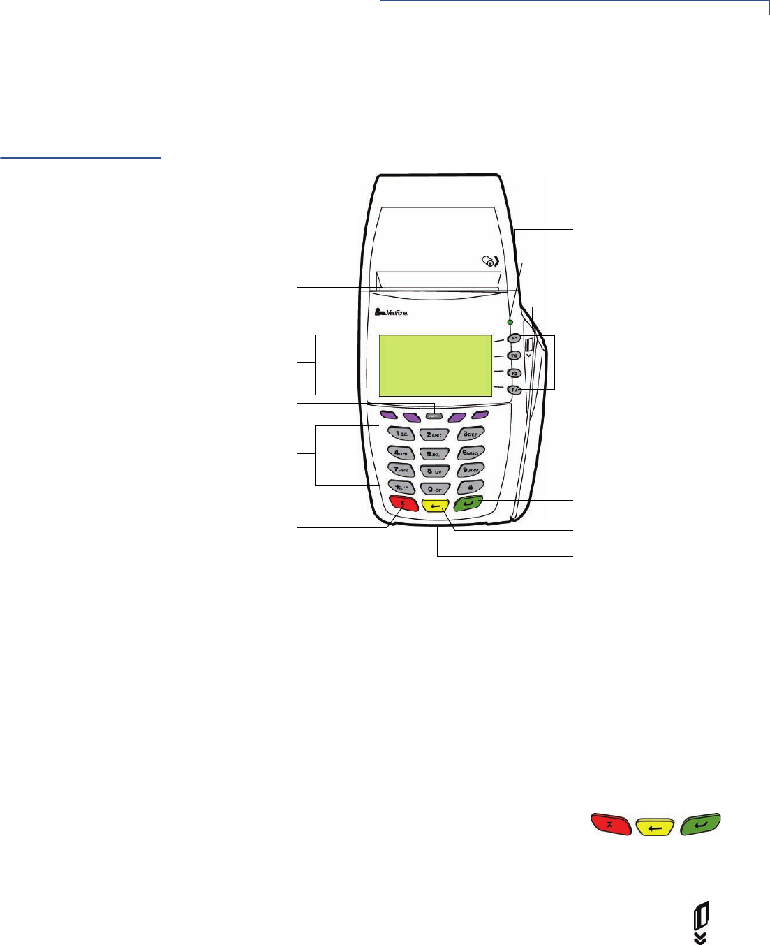
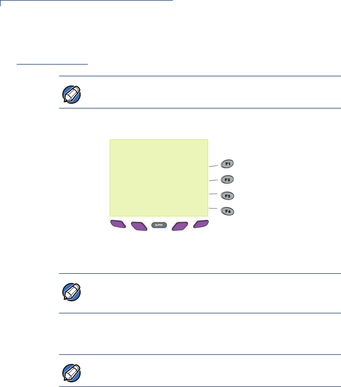
Figure 1 Vx5xx/Vx610 Terminal Features (Front Panel)
Front Panel
The front panel includes the following features:
•A terminal display, backlit LCD screen.
•Five types of keys:
aA 12-key, telephone-style keypad.
bFour ATM-style function keys, labeled F1 to F4, to the right of the LCD
screen.
cFour unlabeled, programmable function keys above the keypad.
dThree color-coded function keys below the
keypad (icons at right; from left to right: CANCEL,
BACKSPACE/CLEAR, ENTER).
eAn ALPHA key centered at the top of the keypad.
•A magnetic card reader, built into the right side. The icon at right
shows the proper swipe direction, with the stripe down and facing
inward, toward the keypad.
•A green indicator LED indicates power is ON.
•An internal thermal printer.
INTERNAL THERMAL
PRINTER PRINTER COVER RELEASE
ATM-STYLE FUNCTION KEYS
TERMINAL DISPLAY
MAGNETIC CARD READER
PROGRAMMABLE FUNCTION
ALPHA KEY
TELEPHONE-STYLE
ENTER KEY
SMART CARD READER
KEYS
KEYPAD
CANCEL KEY BACKSPACE/CLEAR KEY
GREEN INDICATOR LED
SERRATED METAL
STRIP
TERMINAL SETUP
Examining Terminal Features
16 OMNI 5XXX AND VX5XX/VX610 INSTALLATION GUIDE
•A smart card reader, built into the front of the terminal. The icon
shown at right indicates proper card position and insertion
direction.
•A SAM (security access module) compartment, built into the bottom of the
terminal. The Vx5xx/Vx610 terminal contains MSAM cardholders to support
multiple stored-value card programs or other merchant card requirements.
Connection Ports
Turn the terminal upside down to view the connection ports. Notice that the ports
are recessed. Different ports are provided to connect the terminal to a
communications line, optional peripheral devices, and the power supply.
Figure 2 shows the connection ports for the Vx510 terminal.
Figure 2 Vx510 Connection Ports (Bottom View)
NOTE VeriFone ships variants of the Vx5xx/Vx610 terminal for different markets. Your
terminal may have a different configuration. The following devices may or may not
be present: a smart card reader, or zero or three MSAM cardholders. However, the
basic processes described in this guide remain the same, regardless of terminal
configuration.
TERMINAL SETUP
Examining Terminal Features
OMNI 5XXX AND VX5XX/VX610 INSTALLATION GUIDE 17
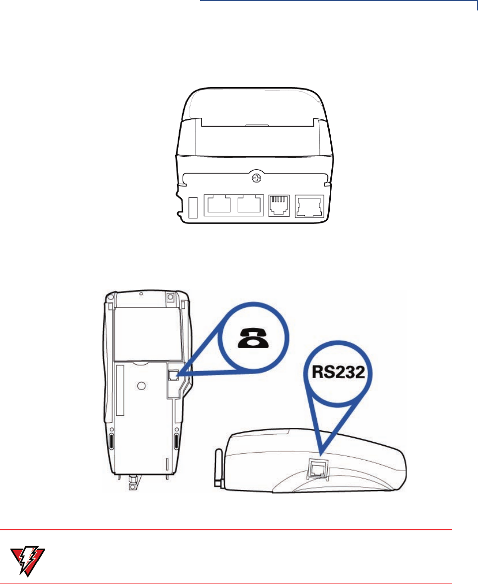
Figure 3 shows the connection port for the Vx570 terminal.
Figure 3 Vx570 Connection Ports (Back View)
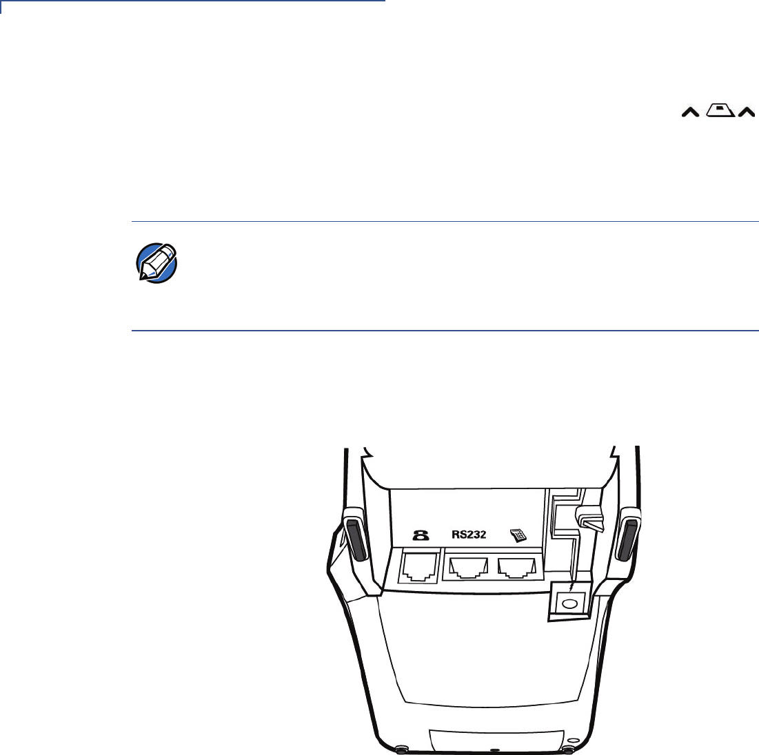
Figure 4 shows the connection ports for the Vx610 terminal.
Figure 4 Vx610 Connection Ports (Bottom and Side Views)
For information on how to attach peripheral devices, see Connecting Optional
Device(s).
WARNING Do not connect the terminal to the power supply until all the peripherals are
attached.
TERMINAL SETUP
Establishing Telephone Line Connections
18 OMNI 5XXX AND VX5XX/VX610 INSTALLATION GUIDE
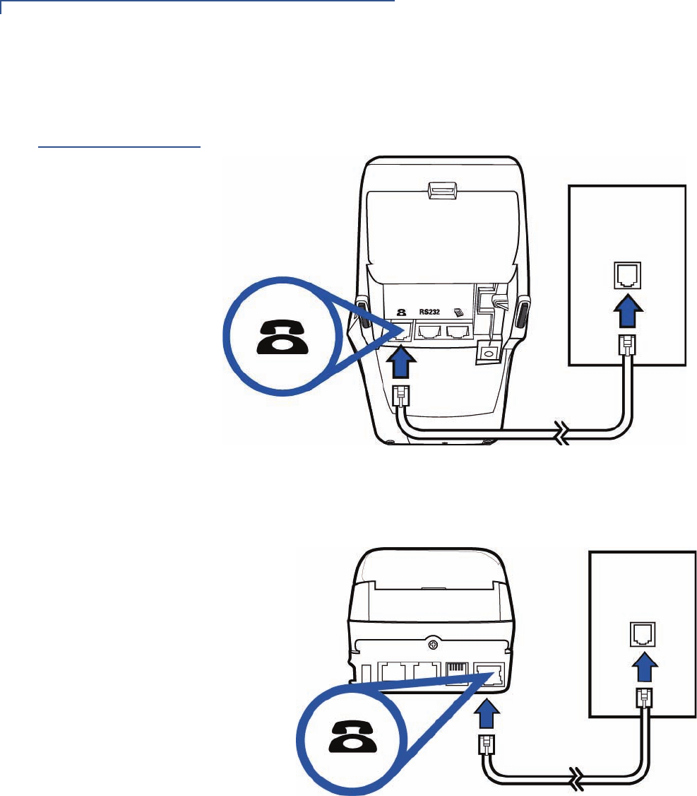
Establishing
Telephone Line
Connections
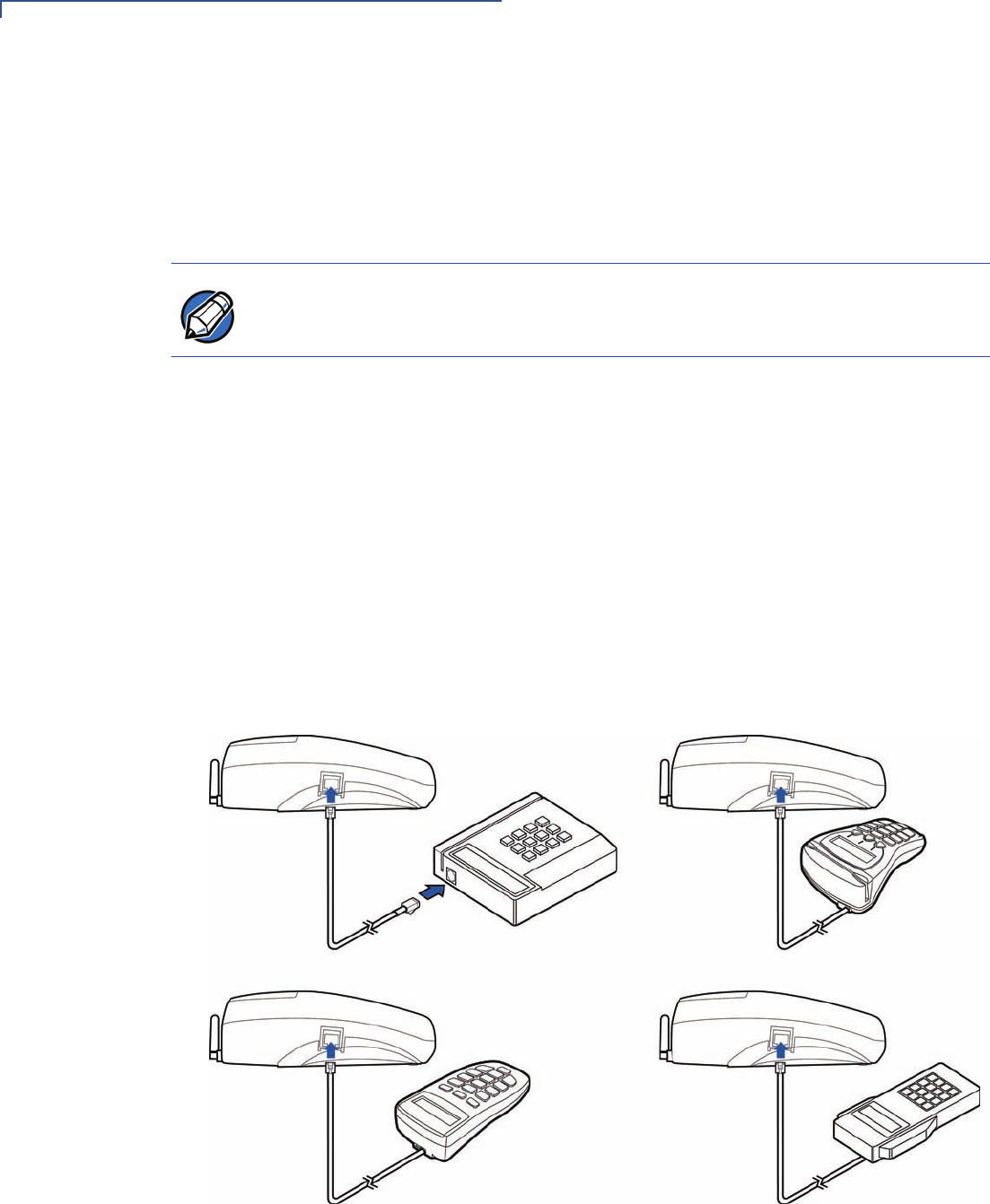
Connect the telephone cord to the communication port on the terminal, then route
it directly to a telephone wall jack (see Figure 5, Figure 6, and Figure 7). This is a
direct connection and the line is dedicated to the terminal.
Figure 5 Vx510 Direct Telephone Connection
Figure 6 Vx570 Direct Telephone Connection
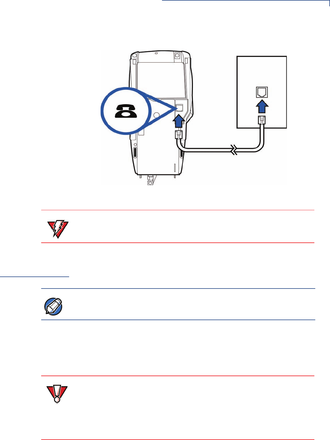
TERMINAL SETUP
Installing the Paper Roll in the Printer
OMNI 5XXX AND VX5XX/VX610 INSTALLATION GUIDE 19
Figure 7 Vx610 Direct Telephone Connection
Installing the
Paper Roll in the
Printer
A fast, quiet thermal printer is built into the Vx5xx/Vx610 terminal. Before you can
process transactions that require a receipt or record, you must install a roll of
thermal-sensitive paper in the printer.
The ITP uses a roll of single-ply, thermal-sensitive paper 57 millimeters (2.24
inches) wide and 25 meters (82 feet) long. A pink out-of-paper indicator line
appears on the edge of the paper approximately 18 inches before the end of the
roll. After this line appears, there is enough paper remaining on the roll to
conclude at least one transaction.
WARNING To reduce the risk of fire, use only No. 26AWG or larger UL Listed or CSA
Certified Telecommunication Line Cord.
NOTE
Vx610 print speed varies depending on battery charge.
CAUTION Poor-quality paper can jam the printer and create excessive paper dust. To order
high-quality VeriFone paper, refer to Accessories and Documentation.
Store thermal paper in a dry, dark area. Handle thermal paper carefully: impact,
friction, temperature, humidity, and oils affect the color and storage
characteristics of the paper.
Never load a roll of paper with folds, wrinkles, tears, or holes at the edges.
TERMINAL SETUP
Installing the Paper Roll in the Printer
20 OMNI 5XXX AND VX5XX/VX610 INSTALLATION GUIDE
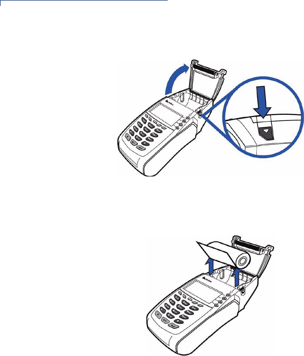
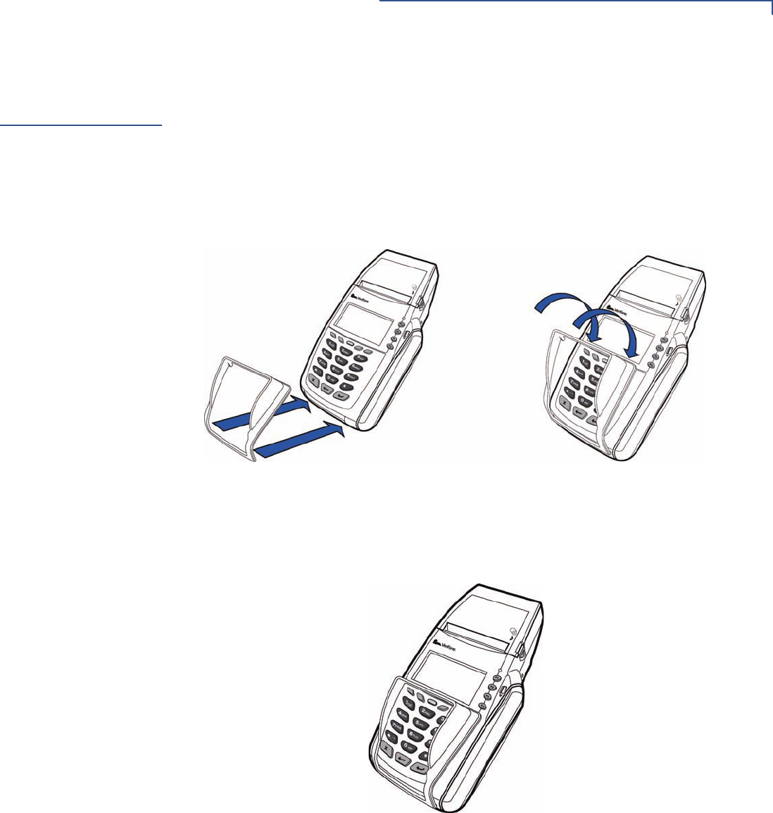
To Install a Paper Roll 1Press down on the button located on the side of the terminal to unlatch the
paper roll cover, then lift the cover up and back (see Figure 8).
Figure 8 Opening the Printer Cover
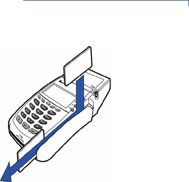
2Remove any partial roll of paper in the printer tray by lifting up (see Figure 9).
3Loosen the glued leading edge of the paper or remove the protective strip
from the new roll of paper. Unwind the paper roll past any glue residue.
Figure 9 Removing Partial Paper Roll
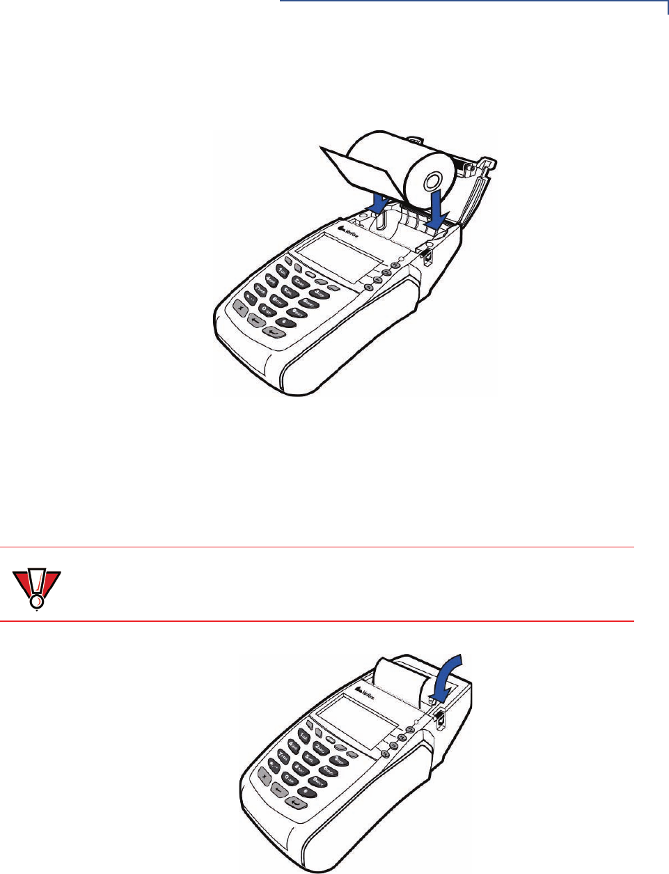
4Hold the roll so the paper feeds from the bottom of the roll (see Figure 10).
TERMINAL SETUP
Installing the Paper Roll in the Printer
OMNI 5XXX AND VX5XX/VX610 INSTALLATION GUIDE 21
5Drop the paper roll into the printer tray.
Figure 10 Loading Paper Roll
6Pull paper up past the glue residue.
7Close the paper roll cover by gently pressing directly on the cover until it clicks
shut, allowing a small amount of paper past the glue residue to extend outside
the printer door. (see Figure 11).
Figure 11 Closing Paper Roll Cover
8Tear the paper off against the serrated metal strip in the printer.
For paper ordering information, refer to Accessories and Documentation.
CAUTION To prevent the paper roll cover from damaging the print roller, always gently press
down on the printer dust cover to close it.
TERMINAL SETUP
Installing/Replacing MSAM Cards
22 OMNI 5XXX AND VX5XX/VX610 INSTALLATION GUIDE
Installing/
Replacing MSAM
Cards
When you first receive your Vx5xx/Vx610 terminal, you may need to install one or
more MSAM cards or you may need to replace old cards.
To Install/Replace
MSAMs
1Remove the power cord and/or battery (see Installing the Vx610 Smart
Battery) from the terminal.
2Place the terminal upside down on a soft, clean surface to protect the lens
from scratches.
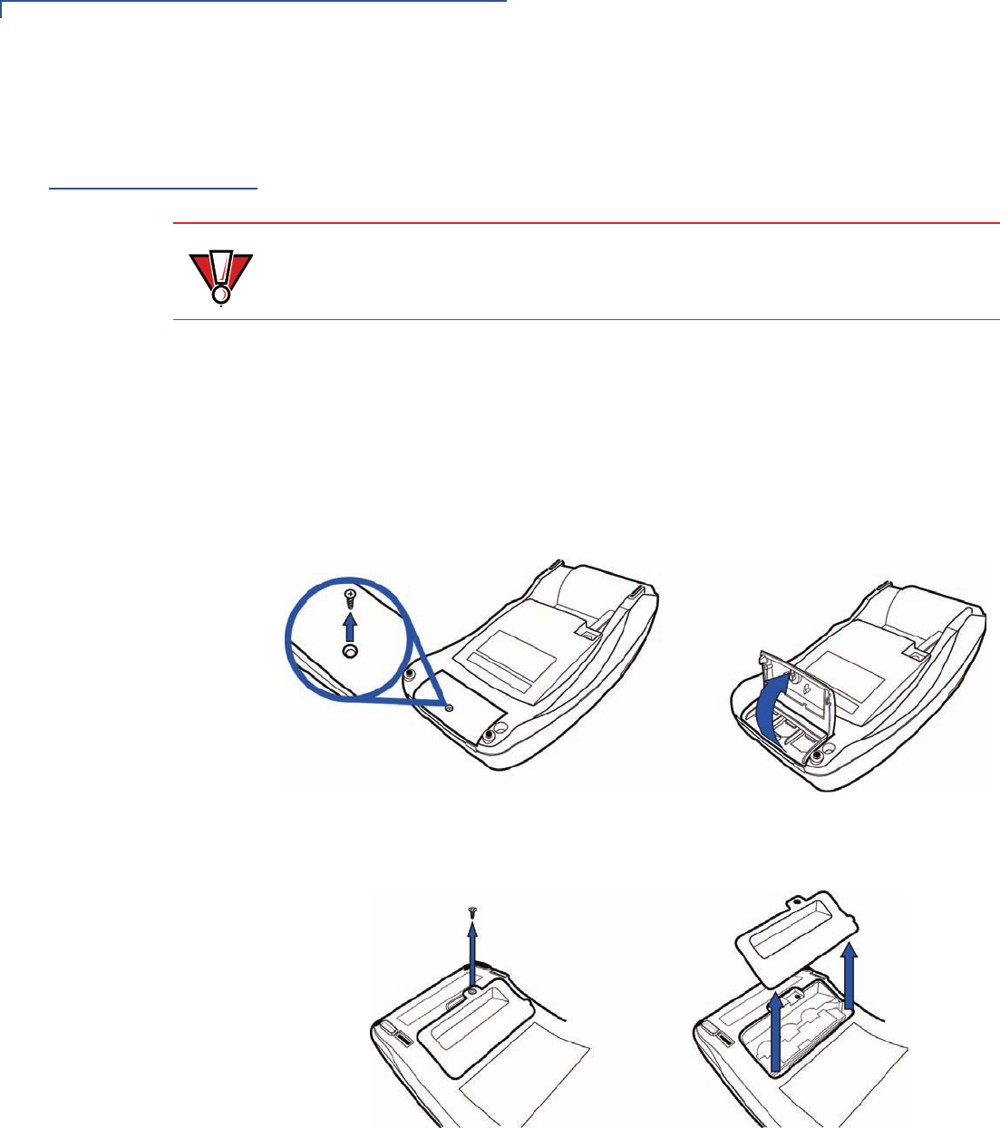
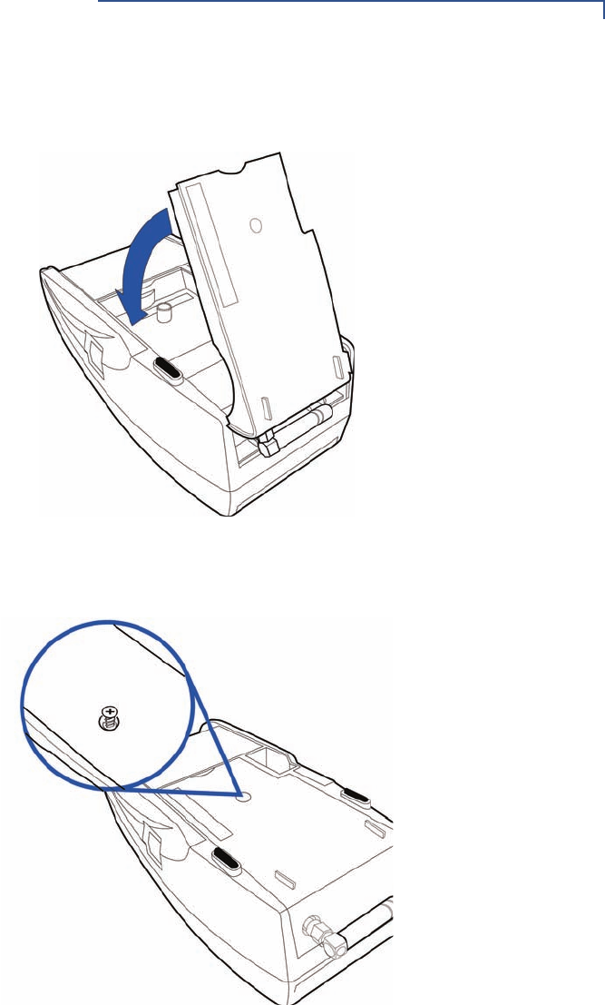
3Remove the MSAM compartment door screw and rotate the door up and back
to access the MSAM cardholders (see Figure 12).
Figure 12 Opening Vx510 MSAM Compartment Door
Figure 13 Opening Vx570 MSAM Compartment Door
CAUTION Observe standard precautions when handling electrostatically sensitive devices.
Electrostatic discharges can damage this equipment. VeriFone recommends
using a grounded anti-static wrist strap.
TERMINAL SETUP
Installing/Replacing MSAM Cards
OMNI 5XXX AND VX5XX/VX610 INSTALLATION GUIDE 23
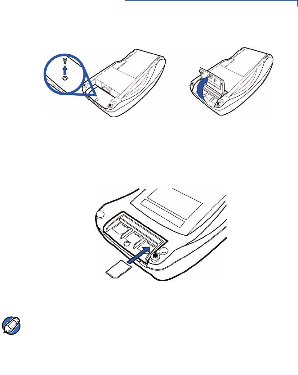
Figure 14 Opening Vx610 MSAM Compartment Door
4Remove any previously installed MSAM card by sliding the card from the
MSAM cardholder.
5Install an MSAM card by aligning the card and carefully sliding it within the
guides on the cover until it is fully inserted (see Figure 15).
Figure 15 Installing an MSAM Card
6Replace the MSAM compartment door and reinstall the screw.
NOTE Before inserting the MSAM card, position it as shown in Figure 15, with the card’s
gold contacts facing the smart car reader end of the terminal. The cardholder
connector base has a set of contacts and a notch on one corner to ensure the
MSAM card is positioned correctly. The MSAM card has a notch on one corner to
ensure that it fits into the connector base in only one way. The MSAM
compartment door will not close properly if the MSAM cards are installed
incorrectly.

TERMINAL SETUP
Connecting Optional Device(s)
24 OMNI 5XXX AND VX5XX/VX610 INSTALLATION GUIDE
Connecting
Optional
Device(s)
The Vx5xx/Vx610 series of terminals supports some peripheral devices designed
for use with electronic point-of-sale terminals.
Different terminals support different devices, so for more information about
optional devices, please contact your VeriFone distributor.
V
x
510 and V
x
570
Optional Device
Connections
For the Vx510 and Vx570, use the two ports on the back panel to connect up to
two optional devices.
Connecting the PINpad or Smart Card Reader to the V
x
510
or V
x
570
Use the following procedure to connect a PINpad or smart card reader.
1Insert the RJ45-type connector on the end of the PINpad or smart card reader
into the port on the back of the peripheral device.
To install a PINpad 101, PINpad 201, or PINpad 1000, position and insert the
grommet to secure the cable connection.
If a cable is not already connected to the smart card reader or PINpad, insert
the small modular plug on one end of the interface cable into the optional
device’s modular jack.
CAUTION Before connecting any peripheral device, remove the power cord and/or battery
(see Installing the Vx610 Smart Battery) from the terminal and ensure that the
green indicator LED is not lit. Reconnect the power cord and/or battery only after
you are finished connecting the peripheral device(s). For complete information
about peripheral installation and use, refer to the user documentation supplied
with those devices.
NOTE RS-232-type devices do not work on the PINpad port. PINpad-type devices do not
work on the RS-232 port. If an optional peripheral device does not function
correctly, check the port connection.
TERMINAL SETUP
Connecting Optional Device(s)
OMNI 5XXX AND VX5XX/VX610 INSTALLATION GUIDE 25
2Insert the larger RJ45-type connector on the other end of the PINpad cable
into the PINpad serial port on the bottom of the terminal.
Figure 16 Vx510 Example PINpad Serial Port Connections
Connecting the Check Reader to the V
x
510
or V
x
570
The Vx5xx terminal supports the CR 600 and CR 1000i check readers. Contact
your VeriFone representative or visit the online store a www.store.verifone.com for
information on these devices. Figure 17 provides an example of a peripheral
connection to the RS-232 port.
Figure 17 Vx510 Example Check Reader Connection
CAUTION Check readers require a separate power source. Before connecting a check
reader or similar device, remove the power cord and/or battery (see Installing the
Vx610 Smart Battery) from the bottom of the terminal and ensure that the green
indicator LED is not lit.
TERMINAL SETUP
Connecting Optional Device(s)
26 OMNI 5XXX AND VX5XX/VX610 INSTALLATION GUIDE
V
x
610 Optional
Device Connections
The side port of the Vx610 terminal can operate either as a PINpad port or an RS-
232 port, depending on the power source available.
Connecting the PINpad or Smart Card Reader to the Vx610
Use the following procedure to connect a PINpad or smart card reader.
1Insert the RJ45-type connector on the end of the PINpad or smart card reader
into the port on back of the peripheral device.
To install a PINpad 101, PINpad 201, or PINpad 1000, position and insert the
grommet to secure the cable connection.
If a cable is not already connected to the smart card reader or PINpad, insert
the small modular plug on one end of the interface cable into the optional
device’s modular jack.
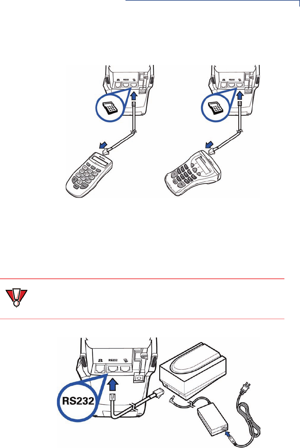
2Insert the larger RJ45-type connector on the other end of the PINpad cable
into the PINpad serial port on the side of the terminal. Figure 18 provides an
example of a smart card reader and PINpad connection to the PINpad serial
port.
Figure 18 Vx610 Example PINpad Serial Port Connections
NOTE When the Vx610 terminal is powered via the corded power supply, the terminal
provides 400 mA at 9V DC to the side port. This power will drive most VeriFone
accessories. Contact your local VeriFone representative for more information.
TERMINAL SETUP
Connecting Optional Device(s)
OMNI 5XXX AND VX5XX/VX610 INSTALLATION GUIDE 27
Connecting the Check Reader to the Vx610
The Vx610 terminal also supports the CR 600 and CR 1000i check readers.
Contact your VeriFone representative or visit the online store at
www.store.verifone.com for information on these devices.
Figure 19 provides an example of a peripheral connection to the RS-232 port.
Figure 19 Vx610 Example Check Reader Connection
External Printers
Supported
Although all Vx5xx/Vx610 variants have an internal thermal printer, it may be
convenient to print larger print runs (for example, daily or weekly reports) to an
external printer. The Vx5xx/Vx610 terminal supports the VeriFone P250, P350,
P900, and P950 external printers. Contact your VeriFone representative or visit
the online store at www.store.verifone.com for information on these devices.
External printers connect through the RS-232 port and require a separate power
supply.
CAUTION Check readers require a separate power source. Before connecting a check
reader or similar device, remove the power cord and/or battery (see Installing the
Vx610 Smart Battery) from the bottom of the terminal and ensure that the green
indicator LED is not lit.
TERMINAL SETUP
Connecting the Terminal Power Pack
28 OMNI 5XXX AND VX5XX/VX610 INSTALLATION GUIDE
Connecting the
Terminal Power
Pack
When you have finished connecting optional peripheral(s), you are ready to
connect the Vx5xx/Vx610 terminal to the provided power source.
To Connect the
Terminal Power Pack
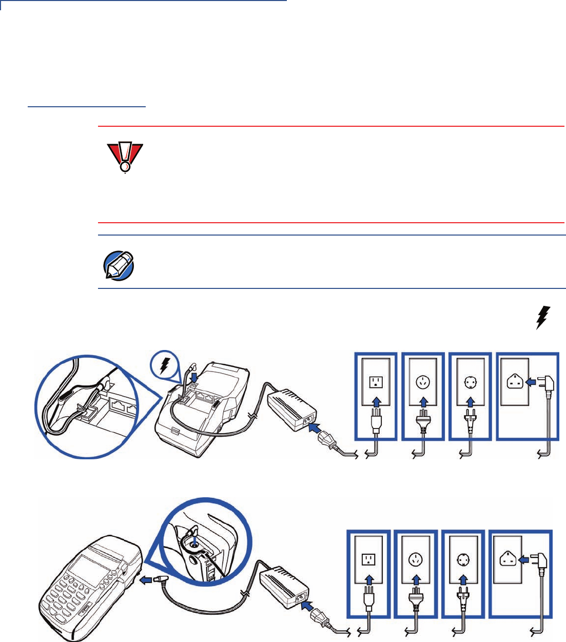
1Insert the round barrel connector (see Figure 20, Figure 21 and
Figure 22) into the power port, identified by the icon at right.
Figure 20 Vx510 Power Pack Connection
Figure 21 Vx570 Power Pack Connection
CAUTION Using an incorrectly rated power supply may damage the terminal or cause it not
to work as specified. Before troubleshooting, ensure that the power supply being
used to power the terminal matches the requirements specified on the bottom of
the terminal. (See Chapter 3, Specifications, for detailed power supply
specifications.) Obtain the appropriately rated power supply before continuing
with troubleshooting.
NOTE
Plugging in the power pack to a power source automatically turns on the terminal.
TERMINAL SETUP
Connecting the Terminal Power Pack
OMNI 5XXX AND VX5XX/VX610 INSTALLATION GUIDE 29
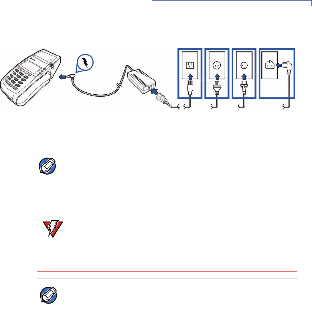
Figure 22 Vx610 Power Pack Connection
1Route the cable through cable retainer where provided to secure the power
cord.
2Insert the AC power cord into the power pack.
3Plug the AC power cord into a wall outlet or powered surge protector.
When the terminal has power, the terminal lights are activated and the green LED
indicator remains lit.
If an application is loaded in the terminal, it starts after the initial VeriFone
copyright screen and usually displays a unique copyright screen. If no application
is loaded in the terminal, DOWNLOAD NEEDED appears on screen after the initial
VeriFone copyright screen.
NOTE The bottom of the Vx510 and Vx570 terminals have an integrated cable-retaining
feature to secure the power cord to the terminal. The battery-based Vx610 does
not need this feature.
WARNING Do not plug the power pack into an outdoor outlet or operate the terminal
outdoors.
Disconnecting the power during a transaction may cause transaction data files
not yet stored in terminal memory to be lost.
To protect against possible damage caused by lightning strikes and electrical
surges, consider installing a power surge protector.
NOTE VeriFone recommends connecting wall power in the following order:
1First, connect the terminal to the power supply.
2Next, connect the power supply to the power cord.
3And last, connect the power cord to the wall outlet.
TERMINAL SETUP
Vx610 Battery Behavior (No Power Cord)
30 OMNI 5XXX AND VX5XX/VX610 INSTALLATION GUIDE
V
x
610 Battery
Behavior (No
Power Cord)
When you have finished connecting optional peripheral(s), you are ready to power
the Vx610 terminal from the attached battery.
Manual Startup
Hold the green key down through a series of short beeps until the terminal
displays the startup screen.
Figure 23 Vx610 Startup Screen
When the terminal has power, the terminal lights are activated and the green LED
indicator remains lit.
Manual Shutdown
Hold the red key down through a series of short beeps until the terminal displays
the shutdown verification screen. Keep holding the red key until the Vx610
terminal shuts down.
NOTE If you connect the Vx610 to a non-battery power source, the terminal shifts to
corded power mode and starts up automatically, regardless of the battery charge
state.
VERIFONE OMNI
QB0106A3
12/02/2005 VERIX
*DEFAULT CERTIFICATE*
COPYRIGHT 1997-2005
VERIFONE
ALL RIGHTS RESERVED
BATTERY 98% STAT F4
NOTE If an application is loaded in the terminal, it starts after the initial VeriFone
copyright screen and usually displays a unique copyright screen. If no application
is loaded in the terminal, DOWNLOAD NEEDED appears on screen after the initial
VeriFone copyright screen.
NOTE When the terminal has no power, the screen is blank and the green LED indicator
is not lit.
TERMINAL SETUP
Installing the Privacy Shield
OMNI 5XXX AND VX5XX/VX610 INSTALLATION GUIDE 31
Installing the
Privacy Shield
The privacy shield protects the customers’ PIN entry from being seen by the
cashier or other customers.
V
x
510/V
x
610 Privacy
Shield
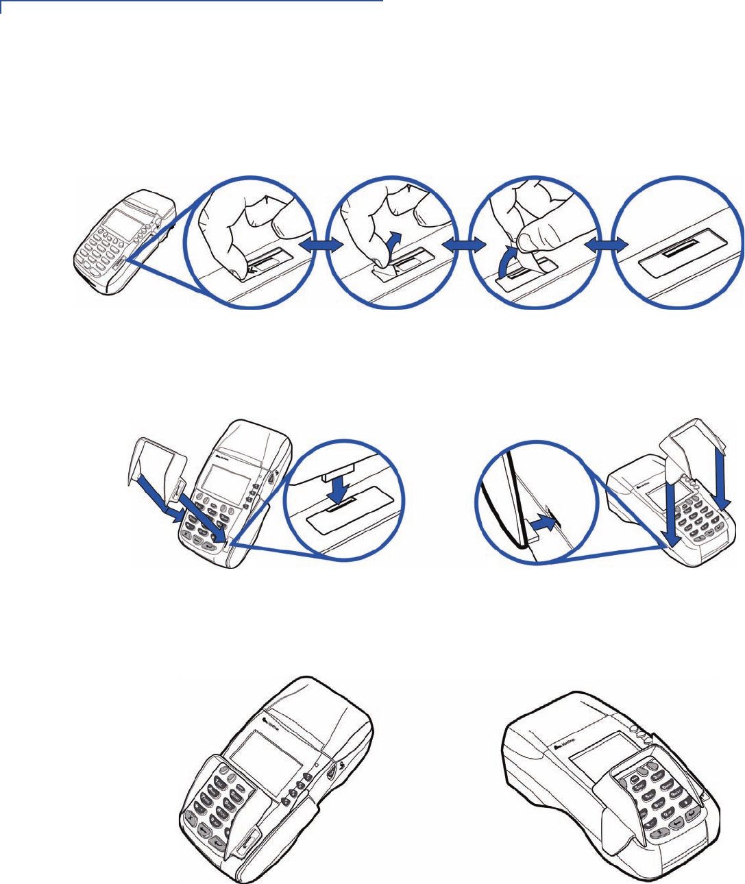
To install the Vx510/Vx610
privacy shield:
1Align the privacy shield with the Vx510/Vx610 terminal and carefully insert the
shield. Make sure that the privacy shield window clears all keys.
Figure 24 Insert the Vx510/Vx610 privacy shield
2Press firmly on all edges around the privacy shield to ensure it is correctly
seated.
Figure 25 Make sure that the privacy shield is properly seated
TERMINAL SETUP
Installing the Privacy Shield
32 OMNI 5XXX AND VX5XX/VX610 INSTALLATION GUIDE
V
x
570 Privacy
Shield
To install the Vx570 privacy shield:
1Remove the sticker (identified by the magnetic card reader icon) located on
the right hand side of the telephone-style keypad.
Figure 26 Remove the sticker
2Align the privacy shield with the Vx570 terminal and carefully insert the shield.
Make sure that the privacy shield window clears all keys.
Figure 27 Insert the Vx570 privacy shield
3Press firmly on all edges around the privacy shield to ensure it is correctly
seated.
Figure 28 Make sure that the privacy shield is properly seated
TERMINAL SETUP
Installing the Vx610 Smart Battery
OMNI 5XXX AND VX5XX/VX610 INSTALLATION GUIDE 33
Installing the
V
x
610 Smart
Battery
Vx610 wireless terminals use Li-ion smart batteries (see Accessories and
Documentation for ordering information). The internal logic of the smart battery
prevents both overcharging and undercharging (a fault condition in which the
battery level goes well below the minimum acceptable charge and the battery
becomes unusable).
The following are features of the smart battery:
•Two Li-ion cells
•A “fuel gauge” module that
•monitors state of charge (voltage and percentage of capacity),
•communicates with the terminal (charge parameters and status),
•determines full charge capacity (on charge cycle and uninterrupted
discharge cycle), and
•automatically shuts down when cell voltage is extremely low.
•A safety circuit that
•prevents cell damage from overcharge, over-discharge, or overheating
•activates when the battery is left in an unused terminal for extended
periods.
Installation
The Vx610 smart battery fits in a slot on the back of the Vx610 terminal, as shown
in Figure 29. The locking tab clicks when the battery is in place. The slot is keyed,
so that there is only one way to insert the battery.
Figure 29 Install the Smart Battery
NOTE The Vx610 terminal will operate on battery power or on power pack power. The
smart battery charger in the terminal will be active whenever the power pack is
connected.
NOTE Conserve battery power by turning the Vx610 terminal off when not in use. If the
terminal is not to be used for several days, remove the battery from the terminal
as it continues to discharge even when the terminal is turned off.
TERMINAL SETUP
Installing the Vx610 Smart Battery
34 OMNI 5XXX AND VX5XX/VX610 INSTALLATION GUIDE
Removal
To remove the Vx610 smart battery, press the locking tab at the top of the battery
and pull the smart battery from its slot.
Figure 30 Detaching the Smart Battery from the Vx610 Terminal
Charging
After unpacking your Vx610 terminal, install the battery and connect the power
pack to the unit for 6 hours. Failure to do so may result in inaccurate battery status
messaging.
VeriFone also recommends that the smart battery receive a periodic full
discharge. To ensure a full discharge, use the unit until the battery is fully drained.
The smart battery has a safety circuit to protect the Li-ion cells from overcharging
and over-discharging. If the battery is over-discharged, the safety circuit shuts
down the battery. The battery must then be recharged to restore operation.
Battery Life
The Vx610 smart battery can be charged and discharged hundreds of times, but
will eventually wear out. When operating times are noticeably shorter than usual,
it is time to buy a new battery (see Accessories and Documentation for ordering
information).
NOTE The Vx610 terminal automatically shuts off when the smart battery reaches the
critically low charge state. If this occurs, the smart battery must be recharged for a
minimum of 1/2 hour before it can power the terminal. It may take several
recharge attempts to reset the safety circuit when charging a smart battery that
has been discharged below this critical state.
WARNING Do not dispose of batteries in a fire. Li-ion batteries must be recycled
or disposed of properly. Do not dispose of Li-ion batteries in municipal
waste sites.
TERMINAL SETUP
Using the Vx610 Spare Battery Charger
OMNI 5XXX AND VX5XX/VX610 INSTALLATION GUIDE 35
Using the V
x
610
Spare Battery
Charger
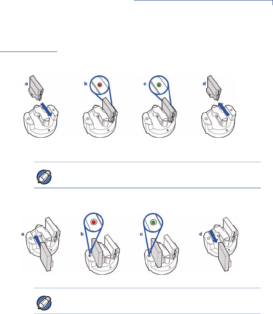
The Vx610 spare battery charger can charge two batteries at a time. The LED
indicator allows you to see the initial battery condition as well as the charging
condition.
To charge a battery 1Insert the battery by sliding it into place.
Figure 31 Charging a single battery
2Notice the LED indicator located on each side of the battery charger.
3Once the battery is fully charged, remove the battery by sliding it upward or
downward depending on which side of the charger is used.
Figure 32 Charging two batteries
NOTE A red light indicates that the battery is charging while the LED changes to green
to indicate that the charge has been completed.
NOTE For best results, when first charging a new battery, charge it in a powered
terminal, instead of charging it with the Vx610 spare battery charger.
TERMINAL SETUP
Using the Vx610 Power Cradle
36 OMNI 5XXX AND VX5XX/VX610 INSTALLATION GUIDE
Using the V
x
610
Power Cradle
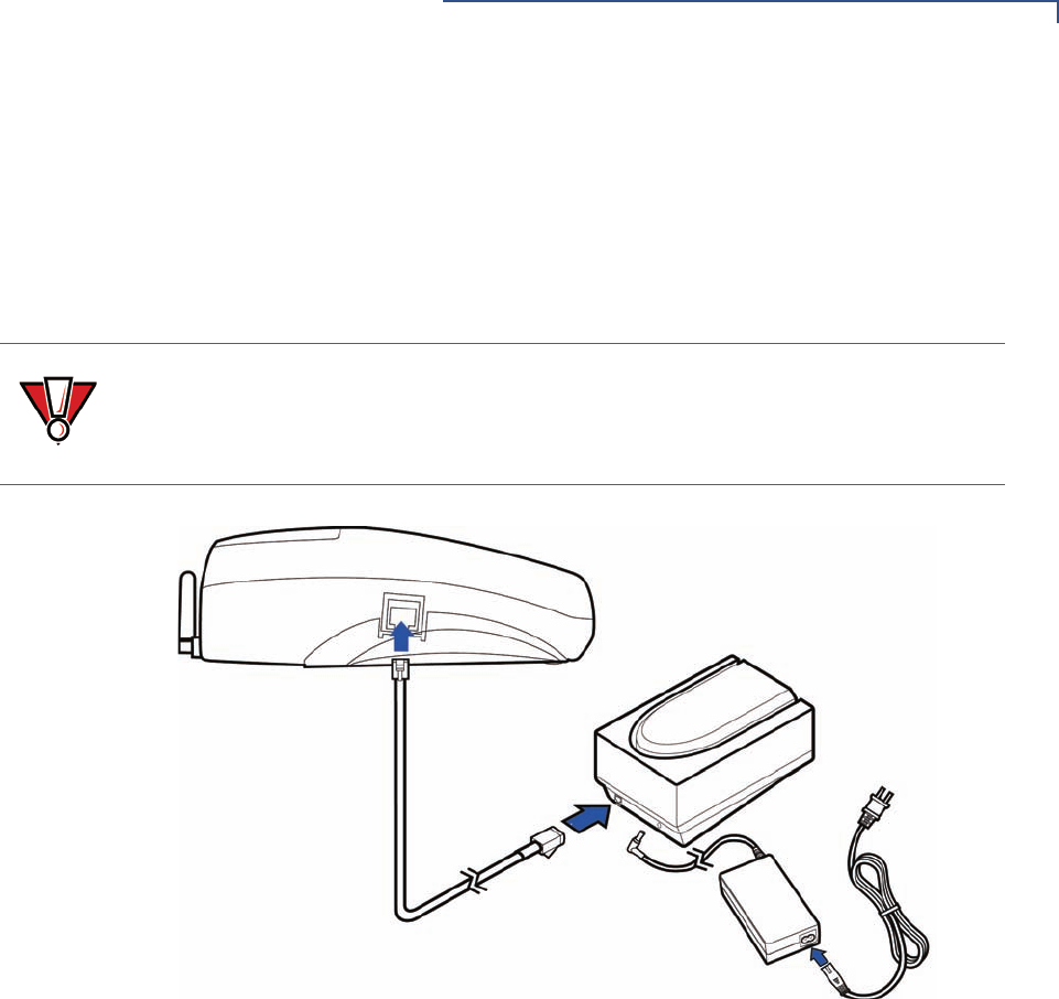
The power cradle serves both as a docking station and a battery charger for the
Vx610 terminal.
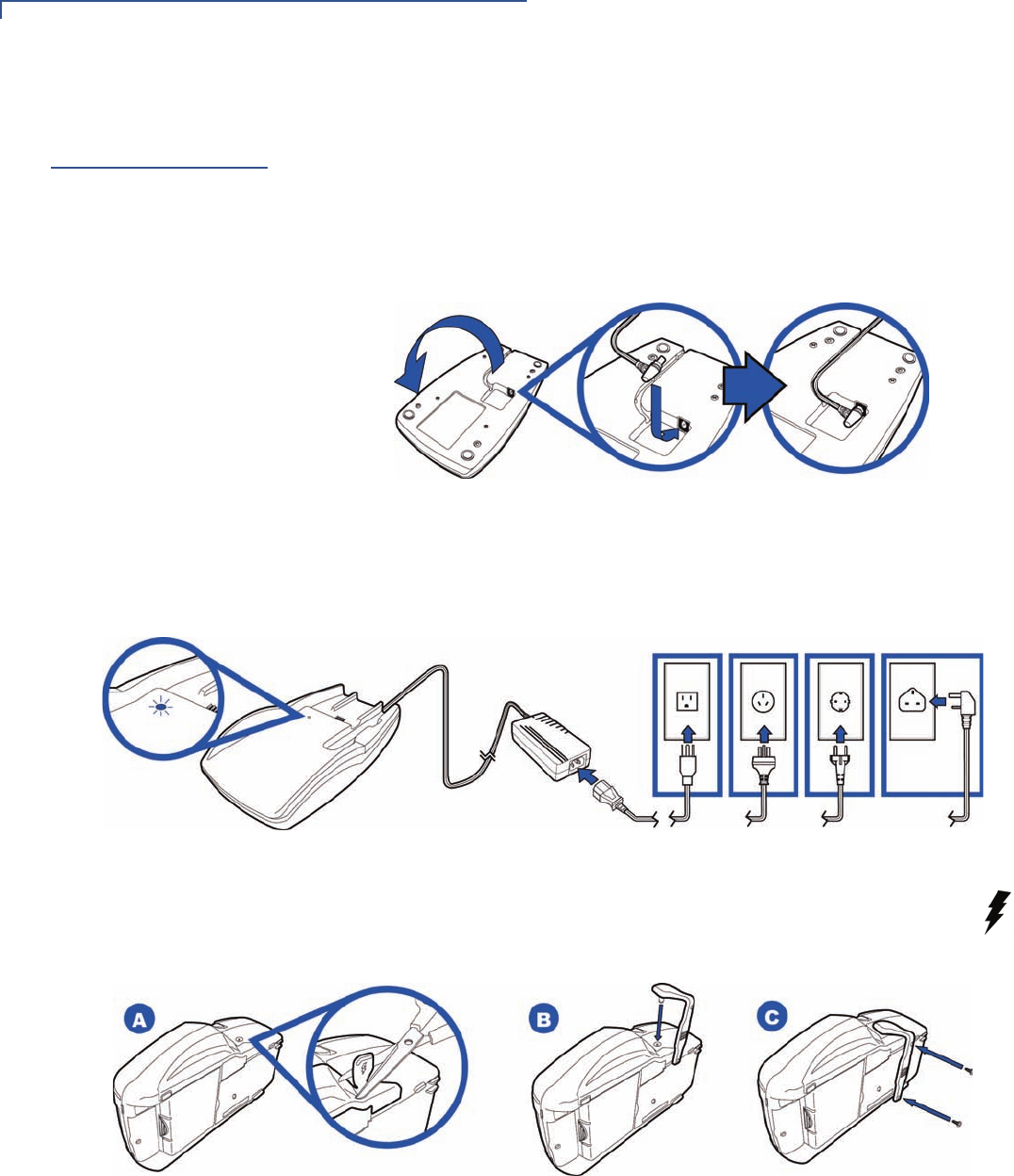
To Connect the Power
Cradle
1Turn the cradle upside down and then insert round barrel connector into the
power port. Route the cable through the cable retainer where provided to
secure the power cord.
Figure 33 Vx610 Power Cradle Connection
2Insert the AC power cord into the power pack and then plug the AC power
cord into a wall outlet or power surge protector. The LED lits up to indicate that
it is ready for charging.
Figure 34 Vx610 Power Cradle Connection
3Remove the protector, identified by the icon at right. Attach the
charging strap and then install the screw on the bottom of the power
cradle to secure the strap.
Figure 35 Vx610 Power Cradle Connection
TERMINAL SETUP
Installing/Replacing the SIM Card (GSM/GPRS Models)
OMNI 5XXX AND VX5XX/VX610 INSTALLATION GUIDE 37
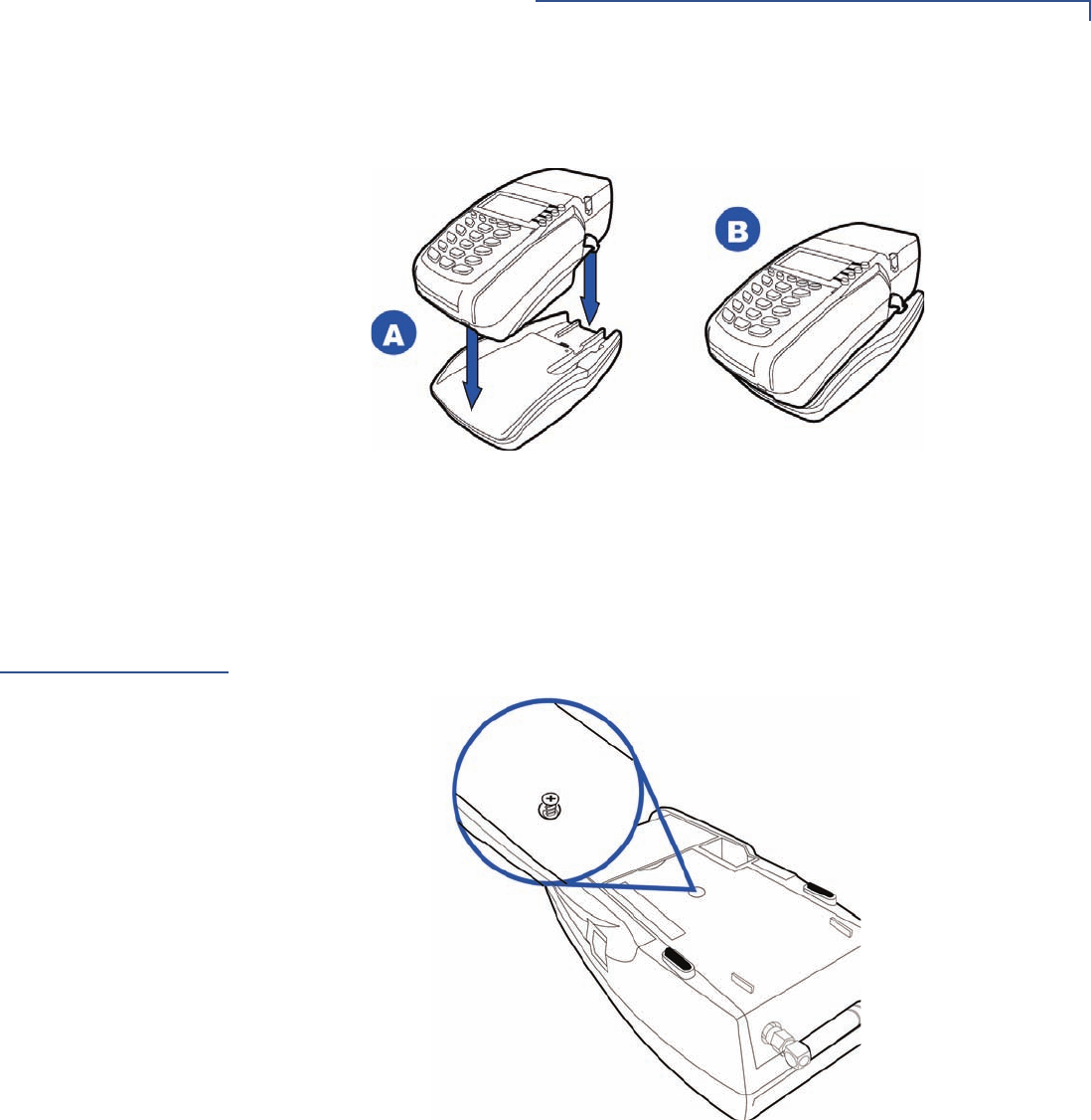
4Place the terminal onto power cradle.
Figure 36 Placing the Vx610 Terminal Onto the Power Cradle
Installing/
Replacing the
SIM Card
(GSM/GPRS
Models)
The SIM (Subscriber Identity Module) card is a smart card inserted in the Vx610
GSM/GPRS terminal that contains your GSM/GPRS radio account information.
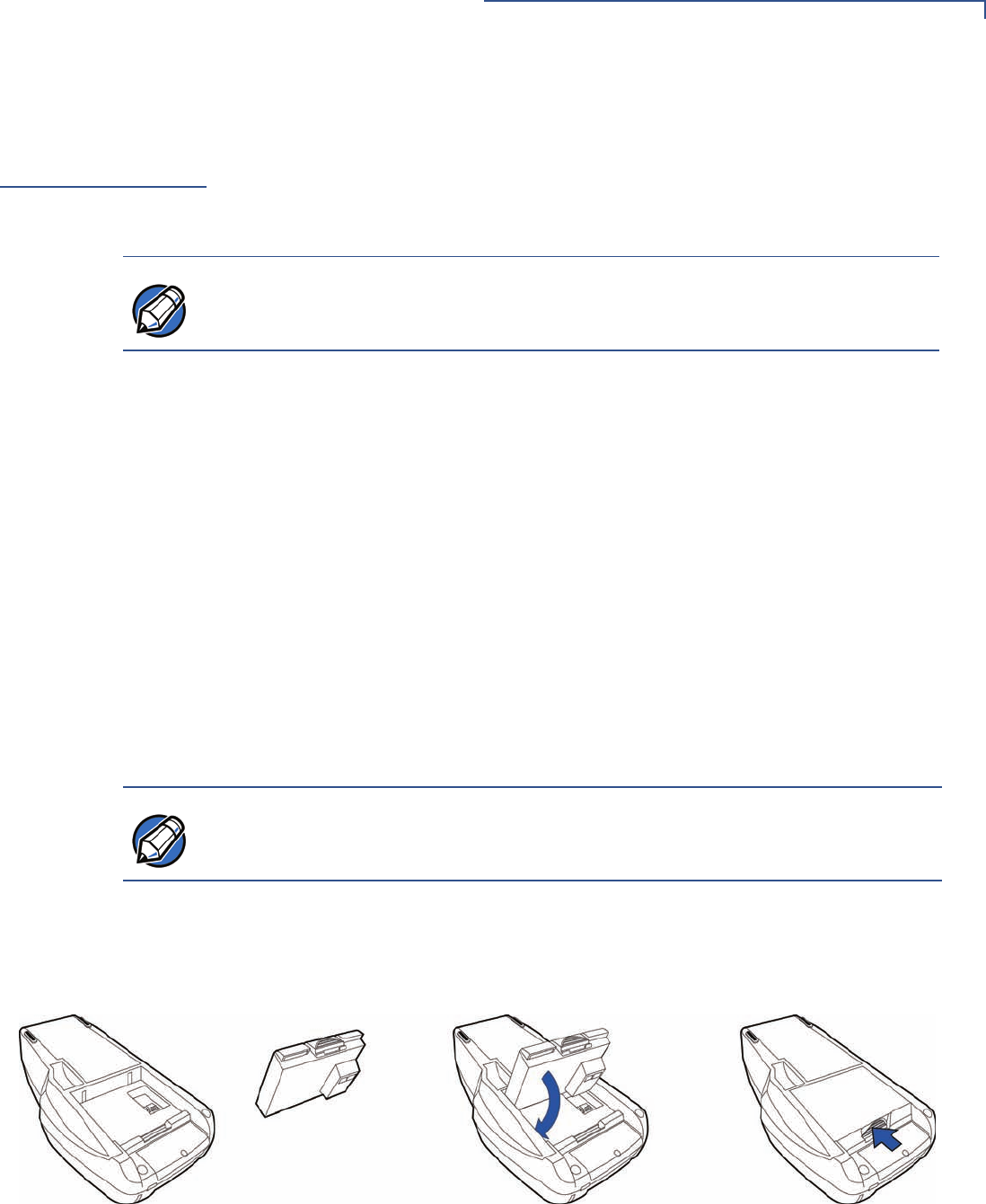
Use the following procedure to replace or install a SIM card.
1Loosen the screw from the GSM/GPRS sled module at the back of the Vx610
terminal.
Figure 37 Loosen Retaining Screw
TERMINAL SETUP
Installing/Replacing the SIM Card (GSM/GPRS Models)
38 OMNI 5XXX AND VX5XX/VX610 INSTALLATION GUIDE
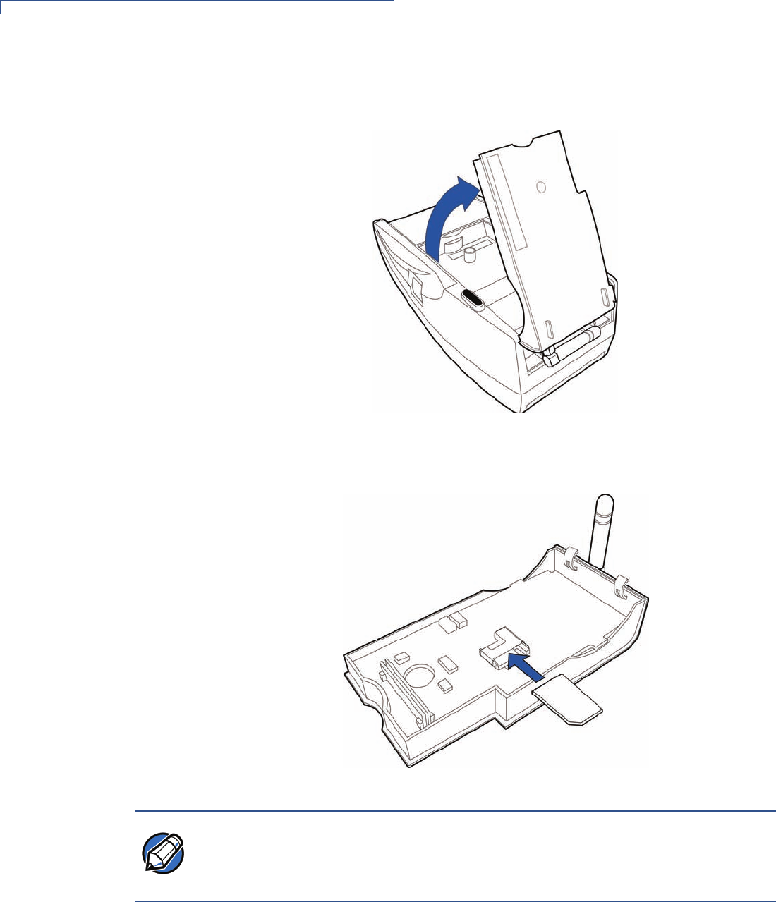
2Detach the GSM/GPRS sled module from the terminal.
Figure 38 Remove GSM/GPRS Sled Module
3Insert the SIM into the cardholder at the back of the GSM/GPRS sled module.
Figure 39 Insert SIM Card Into GSM/GPRS Sled Module
NOTE The SIM cardholder has a notch on one corner to ensure the SIM card is
positioned correctly and for easy orientation in the cardholder. Before inserting
the SIM card, position it as shown in Figure 39, with the card’s gold contacts
facing down.
TERMINAL SETUP
Installing/Replacing the SIM Card (GSM/GPRS Models)
OMNI 5XXX AND VX5XX/VX610 INSTALLATION GUIDE 39
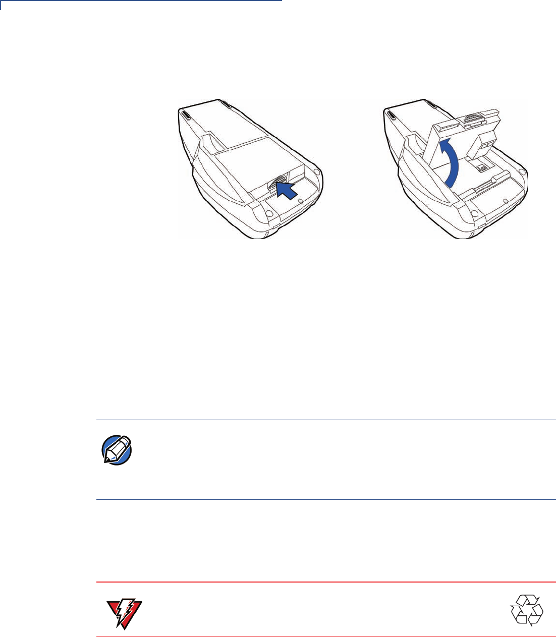
4Replace the GSM/GPRS sled module in the terminal.
Figure 40 Replace GSM/GPRS Module
5Tighten the retaining screw.
Figure 41 Tighten Retaining Screw
TERMINAL SETUP
Connecting the Vx610 External Antenna
40 OMNI 5XXX AND VX5XX/VX610 INSTALLATION GUIDE
Connecting the
V
x
610 External
Antenna
VeriFone provides an external wireless antenna for some Vx610 terminals. This
connection allows communication with your service provider to upload transaction
data from the terminal and download system upgrades to the terminal. Radio
service is activated by your service provider.
Installation
This section only discusses Vx610 terminals with external antenna. If the Vx610
arrives from manufacture with the antenna unattached, use the following
procedure to install the antenna:
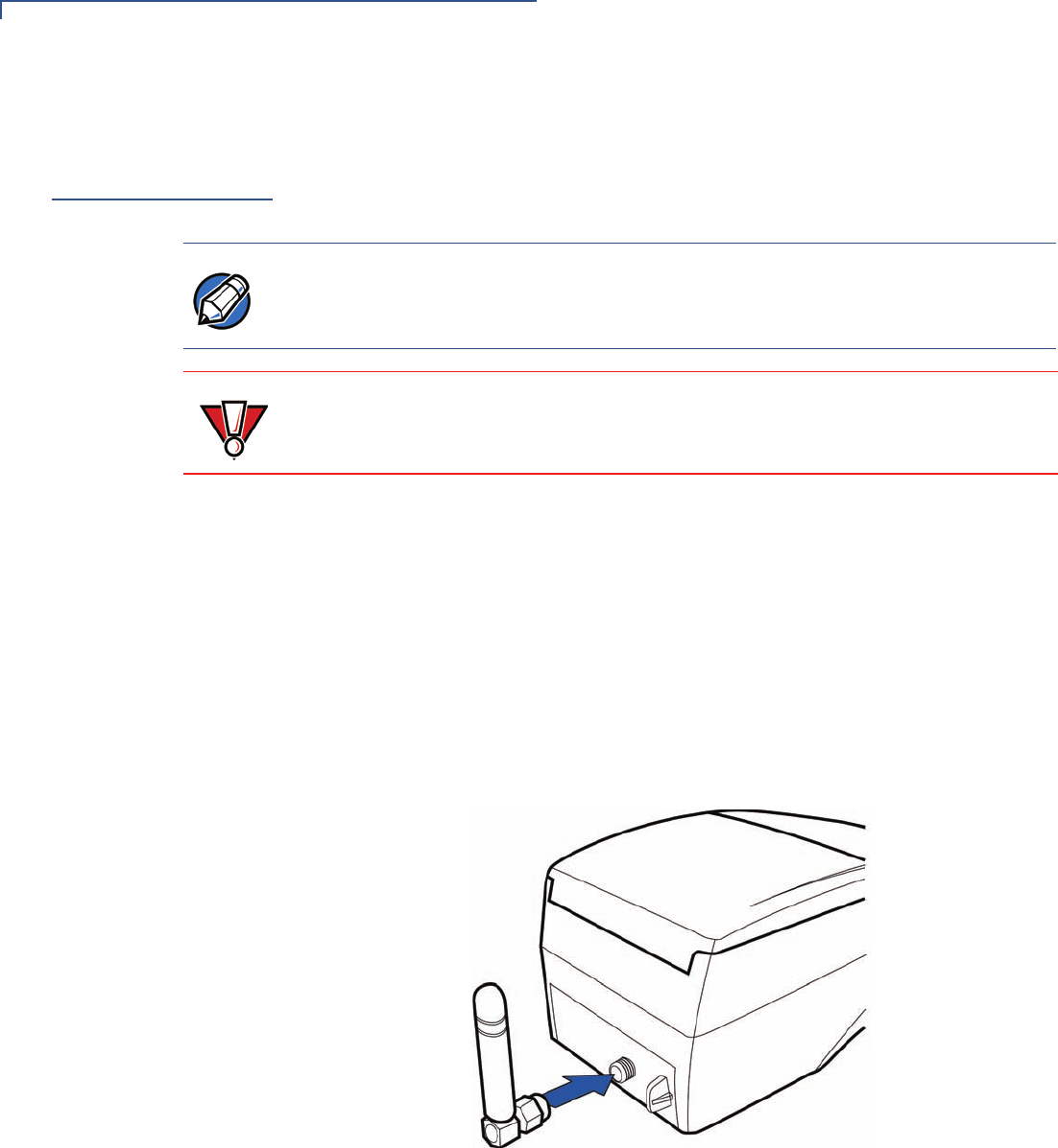
1Locate the antenna port on the back side of the Vx610 terminal.
2Align the connector on the end of the antenna with the connector on the end of
the terminal.
3Push gently on the center of the base of the antenna until it slides into
position.
Figure 42 Align Antenna with Antenna Port
NOTE Some Vx610 terminals have an internal antenna and this section can be ignored.
Use only the antenna designed for your unit. Failure to use the proper antenna
results in the inability to establish a wireless connection.
CAUTION Never hold the unit by the antenna; doing so may break the connection and void
your warranty.
TERMINAL SETUP
Connecting the Vx610 External Antenna
OMNI 5XXX AND VX5XX/VX610 INSTALLATION GUIDE 41
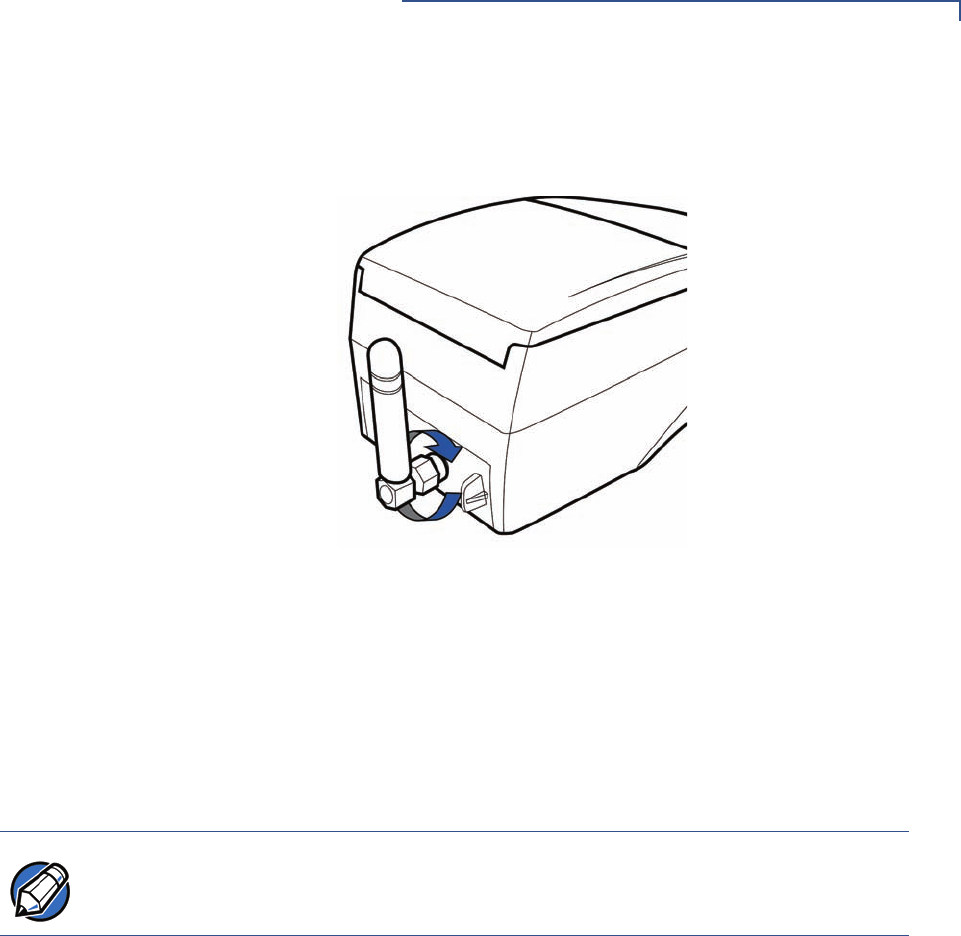
4Screw the barrel nut finger tight to retain the antenna.
Figure 43 Tighten Antenna Barrel Nut
Orientation
To establish good wireless communication (uplink), vertically align the antenna
with respect to ground and sky. For example, if standing and holding the terminal
horizontally, position the antenna approximately at a 90° angle to the unit (that is,
pointing up from the ground). This should point the antenna directly at the sky.
If the unit is on a flat surface (for example, a table top) position the antenna so that
it points directly at the sky.
Replacing the
Antenna
If your Vx610 terminal has difficulties completing wireless transactions, you may
have to replace the antenna. Use the following procedure to replace the antenna:
1Remove the existing antenna from the Vx610 terminal:
aUnscrew the barrel nut to loosen the antenna.
bPull gently on the center of the base of the antenna until it slides out of
position.
2Align the connector on the end of the new antenna with the connector on the
end of the terminal.
3Push gently on the center of the base of the antenna until it slides into
position.
4Screw the barrel nut finger tight to retain the antenna.
NOTE If an application (for example, SoftPay) is installed in your Vx610 unit, a signal
strength indicator may appear on the display.
TERMINAL SETUP
Conducting Wireless Transactions
42 OMNI 5XXX AND VX5XX/VX610 INSTALLATION GUIDE
Conducting
Wireless
Transactions
To conduct a wireless transaction:
•Ensure the terminal is in an optimal position for transmitting.
•Follow the on-screen instructions provided with your application.
Using the Smart
Card Reader
The smart card transaction procedure may vary from one application to another.
Verify the procedure with your application provider before performing a smart card
transaction.
To Conduct a Smart
Card Transaction
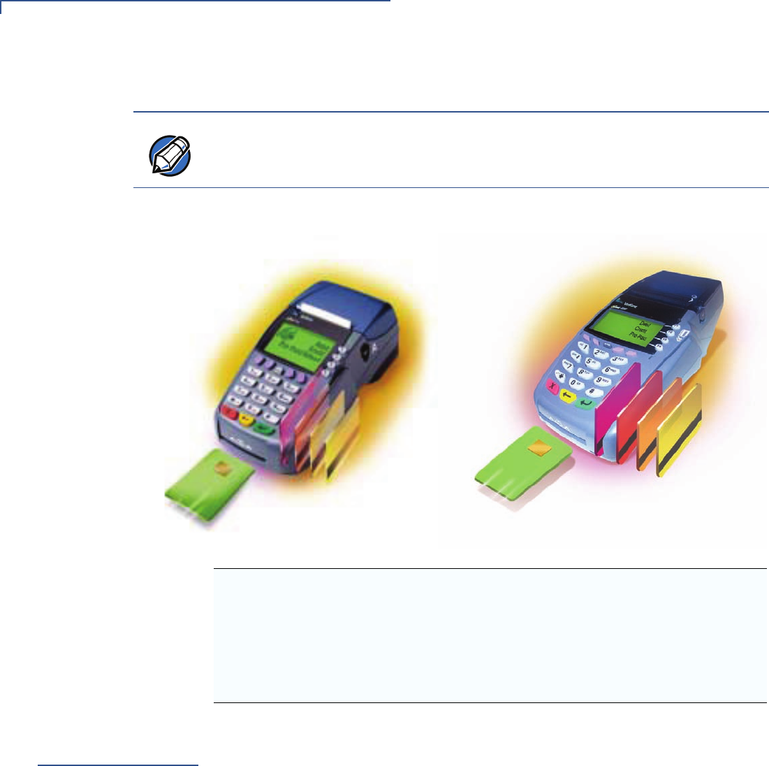
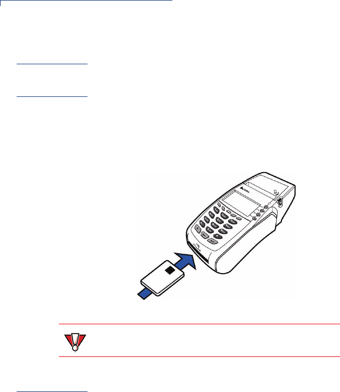
1Position a smart card with the contacts facing upward (see Figure 44).
2Insert the smart card into the smart card reader slot in a smooth, continuous
motion until it seats firmly.
3Remove the card only when the application indicates the transaction is
complete.
Figure 44 Inserting a Smart Card
Using the
Magnetic Card
Reader
The Vx5xx/Vx610 terminal supports credit/debit card transactions.
To Conduct a Credit/
Debit Card
Transaction
1Position a magnetic card with the stripe in the card reader and facing inward,
toward the keypad.
2To ensure a proper read of the magnetic swipe card, the user should insert the
magnetic card from the top of the unit, as shown in Figure 45.
CAUTION Leave the smart card in the card reader until the transaction is complete.
Premature card removal will invalidate the transaction.
TERMINAL SETUP
Using the Magnetic Card Reader
OMNI 5XXX AND VX5XX/VX610 INSTALLATION GUIDE 43
3Swipe the card through the magnetic card reader.
Figure 45 Using the Magnetic Card Reader

TERMINAL SETUP
Using the Magnetic Card Reader
44 OMNI 5XXX AND VX5XX/VX610 INSTALLATION GUIDE
OMNI 5XXX AND VX5XX/VX610 INSTALLATION GUIDE 45
CHAPTER 3
Specifications
This chapter discusses power requirements, dimensions, and other specifications
of the Vx5xx/Vx610 series of terminal.
Power
Vx5xx/Vx610 terminal: 9 V DC; 4.0 A
DC Power Pack
UL, ITE listed, Class 2 power supply:
aInput rated: 100 - 240V AC, 50/60 Hz
bOutput rated: 8.6 - 9.4V DC 4.0 A
Barrel connector polarity:
Temperature
•Operating temperature: 0°
to 40°
C (32°
to 104°
F)
•Storage temperature: -30°
to + 60°
C (-22°
to 140°
F)
•Relative humidity: 5% to 90%; no condensation
External
Dimensions
For Vx510 Terminals:
•Length: 209 mm (8.0 in)
•Width: 102 mm (4.0 in)
•Depth: 72 mm (2.8 in)
For Vx570 Terminals:
•Length: 209 mm (8.0 in)
•Width: 102 mm (4.0 in)
•Depth: 78 mm (3.07 in)
For Vx610 Terminals with Internal Antenna:
•Length: 209 mm (8.0 in)
•Width: 102 mm (4.0 in)
•Depth: 72 mm (2.8 in)

SPECIFICATIONS
SAR Compliance
46 OMNI 5XXX AND VX5XX/VX610 INSTALLATION GUIDE
For Vx610 Terminals with External Antenna:
•Length: 214.2 mm (8.4 in)
•Width: 102 mm (4.0 in)
•Depth: 72 mm (2.8 in)
OMNI 5XXX AND VX5XX/VX610 INSTALLATION GUIDE 47
CHAPTER 4
Maintenance
The Vx5xx/Vx610 terminal has no user-maintainable parts.
Clean the
Terminal
To clean the terminal, use a clean cloth slightly dampened with water and a drop
or two of mild soap. For stubborn stains, use alcohol or an alcohol-based cleaner.
Terminal
Contacts
Gently swab the contacts with alcohol or contact cleaner to remove the dirt. It is
important that the exposed contacts of the Vx610 battery stay clean and unbent.
Smart Card
Reader
Do not attempt to clean the smart card reader. Doing so may void any warranty.
For smart card reader service, contact your VeriFone distributor or service
provider.
CAUTION Never use thinner, trichloroethylene, or ketone-based solvents – they may cause
deterioration of plastic or rubber parts.
Do not spray cleaners or other solutions directly onto the keypad or terminal
display.
CAUTION Avoid touching the contacts in the raised area in the center of the Vx610 battery
and the recessed area on the terminal. Finger oils tarnish contacts, causing bad
connections. When operating on battery power and experiencing a high
occurrence of bad or incomplete data transfers, clean the contacts.

MAINTENANCE
Smart Card Reader
48 OMNI 5XXX AND VX5XX/VX610 INSTALLATION GUIDE

OMNI 5XXX AND VX5XX/VX610 INSTALLATION GUIDE 49
CHAPTER 5
VeriFone Service and Support
For terminal problems, contact your local VeriFone representative or service
provider.
For product service and repair information:
•USA – VeriFone Service and Support Group, 1-800-VeriFone (837-4366),
Monday - Friday, 8 A.M. - 8 P.M., Eastern time
•International – Contact your VeriFone representative
Return a
Terminal or
Smart Battery
for Service
Before returning a Vx5xx/Vx610 terminal, smart battery, or sled module to
VeriFone, you must obtain an MRA number. The following procedure describes
how to return one or more Vx5xx/Vx610 terminals, smart batteries, or sled
modules for repair or replacement (U.S. customers only).
To Return a Terminal
for Service
1Get the following information from the printed labels on the bottom of each
Vx5xx/Vx610 terminal, smart battery, or sled module to be returned:
•Product ID, including the model and part number. For example,
“OMNI 5100” and “Pxxx- xxx-xx,” “Mxxx-xx-xx-xxx,” or “2xxxx-xx”
•Serial number (S/N xxx-xxx-xxx)
2Obtain the MRA number(s) by completing one of the following:
aCall VeriFone toll-free within the United States at 1-800-VeriFone and
follow the automated menu options.
•Select the MRA option from the automated message. The MRA
department is open Monday to Friday, 8 A.M.–8 P.M., Eastern Time.
•Give the MRA representative the information you gathered in Step 1.
If the list of serial numbers is long, you can fax the list, along with the
information gathered in Step 1, to the MRA department at 727-953-
4172 (U.S.).
bAddress a fax to “VeriFone MRA Dept.” with the model and part number(s)
•Include a telephone number where you can be reached and your fax
number.
NOTE International customers are advised to contact their local VeriFone representative
for assistance regarding service, return, or replacement of terminals or batteries.

VERIFONE SERVICE AND SUPPORT
Accessories and Documentation
50 OMNI 5XXX AND VX5XX/VX610 INSTALLATION GUIDE
cComplete the Inquiry Contact Form at http://www.verifone.com/aboutus/
contact/contact_form.cfm.
•Address the Subject box with to “VeriFone MRA Dept.”
•Reference the model and part number in the Note box.
3Describe the problem(s).
4Provide the shipping address where the repaired or replacement unit must be
returned.
5Keep a record of the following items:
•Assigned MRA number(s).
•VeriFone serial number assigned to the Vx5xx/Vx610 terminal, smart
battery, or sled module you are returning for service or repair (terminal
serial numbers are located on the bottom of the unit.
•Shipping documentation, such as air bill numbers used to trace the
shipment.
•Model(s) returned (model numbers are located on the VeriFone label on
the bottom of the Vx5xx/Vx610 terminal).
Accessories
and
Documentation
VeriFone produces the following accessories and documentation for the
Vx5xx/Vx610 terminal. When ordering, please refer to the part number in the left
column.
•VeriFone online store at www.store.verifone.com
•USA – VeriFone Customer Development Center, 800-VeriFone (837-4366),
Monday - Friday, 7 A.M. - 8 P.M., Eastern time
•International – Contact your VeriFone representative
Power Pack
Contact your local VeriFone distributor to determine which power pack or
power cord fits your needs.
CPS10936-3A DC power pack (universal)
21973-01 AC power cord (US)
Thermal Printer
Paper
CRM0039-01 CRM0039 in 30-roll bulk package
CRM0040 High-grade thermal printer paper, 57 mm (2.24-inch) width,
25-meter (82-feet) length; single roll; Available in 20-roll or
50-roll bulk packages
NOTE One MRA number must be issued for each Vx5xx/Vx610 terminal you return to
VeriFone, even if you are returning several of the same model.

VERIFONE SERVICE AND SUPPORT
Accessories and Documentation
OMNI 5XXX AND VX5XX/VX610 INSTALLATION GUIDE 51
VeriFone Cleaning
Kit
02746-01 Cleaning Kit
Telephone Line
Cord
00124-17 2.1-meter (7-foot) telephone line cord, black, with
modular RJ11-type connectors
Swivel Stand
23050-01 Vx510 Swivel Stand
Documentation
For Vx510, Vx570, and Vx610 Terminals:
23216 Omni 5xxx and Vx610 Installation Guide
23217 Omni 5xxx and Vx610 Reference Manual
23230 Verix V Operating System Programmer’s Manual
23231 Verix V Tools Programmer’s Manual
For Vx510 Terminals:
23218 Omni 5100/5150 and Vx510, Omni 3730 Certifications and
Regulations
23219 Omni 5100/5150 and Vx5xx Quick Installation Guide
For Vx570 Terminals:
23646 Vx570 Certifications and Regulations
23759 Vx570 Quick Installation Guide
24134 Vx570 Privacy Shield Quick Installation Guide
For Vx610 Terminals:
23640 Omni 56xx and Vx610 Carrying Case Quick Installation Guide
23641 Omni 56xx and Vx610 Attachable Strap/Handstrap Quick
Installation Guide
23643 Omni 56xx and Vx610 Quick Installation Guide
23644 Omni 56xx and Vx610 Certifications and Regulations
For Vx510 and Vx610 Terminals:
23642 Omni 5xxx and Vx610 Privacy Shield Quick Installation Guide

VERIFONE SERVICE AND SUPPORT
Accessories and Documentation
52 OMNI 5XXX AND VX5XX/VX610 INSTALLATION GUIDE

OMNI 5XXX AND VX5XX/VX610 INSTALLATION GUIDE 53
CHAPTER 6
Troubleshooting
Guidelines
The troubleshooting guidelines provided in the following section are included to
assist you to successfully install and configure your Vx5xx/Vx610 terminal. If you
have problems operating your Vx5xx/Vx610 terminal, please read through these
troubleshooting examples.
If the problem persists even after performing the outlined guidelines or if the
problem is not described below, contact your local VeriFone representative for
assistance. Typical examples of malfunction you may encounter while operating
your Vx5xx/Vx610 terminal and steps you can take to resolve them are listed.
Blank Display
When the terminal display screen does not show correct or clearly readable
information:
•Check terminal power connection.
•Remove and reapply power to the terminal.
•Check all cable connections and verify that the telephone line is properly
connected.
•If the problem persists, contact your local VeriFone service provider.
Terminal Does
Not Dial Out
If the terminal does not dial out:
•Check the telephone line connections.
•Check that the telephone line is working by plugging it into a working
telephone and listening for a dial tone.
NOTE The Vx5xx/Vx610 terminal comes equipped with tamper-evident labels. The
Vx5xx/Vx610 contains no user serviceable parts. Do not, under any circumstance,
attempt to disassemble the terminal. Perform only those adjustments or repairs
specified in this guide. For all other services, contact your local VeriFone service
provider. Service conducted by parties other than authorized VeriFone
representatives may void any warranty.
CAUTION Using an incorrectly rated power supply may damage the terminal or cause it not
to work as specified. Use only a VeriFone-supplied power pack with the correct
output ratings. Before troubleshooting, ensure that the power supply being used
to power the terminal matches the requirements specified on the bottom of the
terminal. (See Chapter 3, Specifications, for detailed power supply
specifications.) Obtain the appropriately rated power supply before continuing
with troubleshooting.

TROUBLESHOOTING GUIDELINES
Printer Paper Jam
54 OMNI 5XXX AND VX5XX/VX610 INSTALLATION GUIDE
•Replace the telephone cable that connects the terminal with a cable you know
is working correctly.
•If the problem persists, contact your local VeriFone service provider.
Printer Paper
Jam
If paper jams inside the printer:
•Press the button on the side of the terminal to unlatch the paper roll cover,
then open the cover.
•Remove the damaged paper from the paper roll and clear the feed
mechanism.
•Install a roll of printer paper, as described in Installing the Paper Roll in the
Printer.
•If the problem persists, it may be due to poor paper quality. Install a new
roll of higher-quality paper.
Keypad Does
Not Respond
If the keypad does not respond properly:
•Check the terminal display. If it displays the wrong character or nothing at all
when you press a key, follow the steps outlined in Transactions Fail To
Process.
•If pressing a function key does not perform the expected action, refer to the
user documentation for that application to ensure you are entering data
correctly.
•If the problem persists, contact your local VeriFone representative.
Peripheral
Device Does Not
Work
If any peripheral device (PINpad or smart card reader) does not work properly:
•Check the power cord connection to the peripheral device.
•Check that the device connected to the proper port has power and is
functioning properly. If possible, perform a self-test on the device in question.
•The cable connecting the optional device to the terminal serial port may be
defective. Try a different serial cable. See Connecting Optional Device(s).
•If the problem persists, contact your local VeriFone representative.
Transactions
Fail To Process
There are several reasons why the terminal may not be processing transactions.
Use the following steps to troubleshoot failures.
Check the Magnetic Card Reader
•Perform a test transaction using one or more different magnetic stripe cards to
ensure the problem is not a defective card.
WARNING Poor-quality paper may jam the printer. To order high-quality VeriFone paper,
refer to Accessories and Documentation.

TROUBLESHOOTING GUIDELINES
Printer Does Not Print
OMNI 5XXX AND VX5XX/VX610 INSTALLATION GUIDE 55
•Ensure that you are swiping cards properly. With the card reader, the black
magnetic stripe on the card should face down and inward, toward the keypad
and must be inserted from the top of the terminal (see Figure 45).
•Process a transaction manually, using the keypad instead of the card reader. If
the manual transaction works, the problem may be a defective card reader.
•Contact your VeriFone distributor or service provider.
•If the manual transaction does not work, proceed to Check the Telephone
Line.
Check the Smart Card Reader
•Perform a test transaction using several different smart cards to ensure the
problem is not a defective card.
•Ensure that the card is inserted correctly and that the card is not removed
prematurely.
•Ensure the MSAM cards are properly inserted in the cardholders and that the
cardholders are properly secured (see Installing/Replacing MSAM Cards).
•Contact your VeriFone distributor or service provider.
•If the manual transaction does not process, proceed to Check the Telephone
Line.
Check the Telephone Line
•Disconnect the telephone line from the terminal and connect it to a working
telephone to check for a dial tone. If there is no dial tone, replace the
telephone cable.
•If the problem appears to be with the telephone line, check with the party you
are trying to call to see if their system is operational. If they are not
experiencing difficulties with their line, contact the telephone company and
have your line checked.
•If the telephone line works, contact your local VeriFone representative for
assistance.
Printer Does Not
Print
If the printer does not work properly:
•Check battery status or terminal power connection. The printer will not print if
there is an insufficient charge remaining in the battery to complete the print
operation. (For Vx610 terminals only.)
•Check if the printer is out of paper and that the roll is properly installed. Open
the paper roll cover and install a new roll of printer paper or ensure that the roll
is feeding from the bottom.
•Verify that the printer roller and paper roll dust cover are properly installed.
•If the problem persists, contact your VeriFone distributor or service provider.

TROUBLESHOOTING GUIDELINES
Terminal Display Does not Show Correct/Readable Information
56 OMNI 5XXX AND VX5XX/VX610 INSTALLATION GUIDE
Terminal Display
Does not Show
Correct/
Readable
Information
•Connect the terminal in to a known-good power supply (if you have one) to
see if this clears the problem.
•Recharge or replace the battery. (For Vx610 terminals only.)
•If the problem persists, contact your local VeriFone representative for
assistance.
V
x
610 Terminal
Does Not Start
•Ensure that you press the ENTER/ON key for approximately 3 seconds, until
the unit lights up.
•Ensure that the smart battery charge state is not below the critically low level.
•Recharge or replace the smart battery.
V
x
610 Smart
Battery Will Not
Charge
Each new Vx610 smart battery must receive a full charge to initialize its full charge
capacity.
Printer Does Not
Print
If the printer does not work properly:
•Check battery status or terminal power connection. The printer will not print if
there is an insufficient charge remaining in the battery to complete the print
operation. (For Vx610 terminals only.)
•Check if the printer is out of paper and that the roll is properly installed. Open
the paper roll cover and install a new roll of printer paper or ensure that the roll
is feeding from the bottom.
•Verify that the printer roller and paper roll dust cover are properly installed.
•If the problem persists, contact your VeriFone distributor or service provider.
NOTE Allow the Vx610 terminal to remain connected to the power pack for 6 hours to
ensure the battery receives a full charge.
Conserve battery power by turning the Vx610 terminal off when not in use. If the
terminal will not be used for several days, remove the battery from the terminal as
it continues to discharge even when the terminal is turned off.
NOTE The Vx610 terminal automatically shuts off when the smart battery reaches the
critically low charge state. If this occurs, the smart battery must recharge a
minimum of 1/2 hour before it can power the terminal. It may take several
recharge attempts to reset the safety circuit when charging a smart battery that
has been discharged below this critical state.

OMNI 5XXX AND VX5XX/VX610 INSTALLATION GUIDE 57
INDEX
A
accessories 50
documentation 51
ordering 51
power packs 50
swivel stand 51
telephone line cord 51
thermal printer paper 50
VeriFone cleaning kit 51
antennas
installation 40
orientation 41
replacing 41
B
batteries
extending the battery life 34
See also smart battery
battery mode
Vx610 30
C
check readers 27
cleaning kit 51
connection ports 16
contact VeriFone 49
D
dial out problems
troubleshooting 53
displays
troubleshooting 53, 56
documentation 50
acronym definitions 7
conventions 7
ordering 51
E
electrical considerations 14, 22
electrostatic discharges 22
prevention 22
environmental factors 13
external printers
RS-232 port connection 27
external printers supported
VeriFone external printers 27
I
installation 9
connecting a check reader to Vx510 or Vx570
25
connecting a check reader to Vx610 27
connecting a PINpad to Vx510 or Vx570 24
connecting a PINpad to Vx610 26
connecting a smart card reader to Vx510 or
Vx570 24
connecting a smart card reader to Vx610 26
connecting a smart card writer to Vx510 or
Vx570 24
connecting optional device(s) 24
connecting the terminal power pack 28
connecting the terminal to a telephone line 18
MSAM cards 22
peripherals 27
terminal location 13
unpacking the shipping carton 14
K
keypads
troubleshooting 54
M
maintenance
cleaning the terminal 47
cleaning the terminal contacts 47
returning a battery for repair or replacement 49
returning a terminal for repair or replacement 49
MSAM cardholders 22
MSAM cards
installation 22
O
optional devices

INDEX
P
58 OMNI 5XXX AND VX5XX/VX610 INSTALLATION GUIDE
connecting 24
P
paper jams
troubleshooting 54
paper rolls
for thermal printers 19, 54
installation 19
peripheral devices
troubleshooting 54
peripherals
check readers 27
installation 27
printers 27
troubleshooting 54
power packs
AC version 50
connecting 28
DC version 50
ordering 50
printer paper
ordering 50
printers
troubleshooting 55, 56
privacy shields 31
Vx510 31
Vx570 32
Vx610 31
S
service
returning a battery for repair or replacement 49
returning a terminal for repair or replacement 49
SIM cards
for GSM models 37
installation 37
smart battery 34
battery life 34
charging 34
conserving power 33
disposal 34
features 33
installation 33
recharging 34
removal 34
troubleshooting 56
specifications
DC power pack 45
power 45
temperature 45
weight 46
T
technical support
contacting VeriFone 49
returning a battery for repair or replacement 49
returning a terminal for repair or replacement 49
telephone line connections 18
telephone line cords
ordering 51
terminal features
general 15
terminals
accessories 50
benefits 10
cleaning 47
documentation 50
electrical considerations 14
environmental factors 13
features 15
repair 49
replacement 49
service and support 49
troubleshooting 53, 56
thermal printer paper
storage 19
thermal printers
about the thermal printer paper 19, 54
paper jams 54
troubleshooting 55, 56
transactions
smart cards 42
wireless 42
troubleshooting
batteries 56
displays 53, 56
guidelines 53
keypads 54
peripheral devices 54
peripherals 54
printers 55, 56
terminal transactions 54

INDEX
V
OMNI 5XXX AND VX5XX/VX610 INSTALLATION GUIDE 59
terminals 53, 56
V
VeriCentre Appliance Management Suite
simultaneous downloads 11
Vx5xx/Vx610
multi-application capability 11
Vx610
starting on battery power 30
troubleshooting 56
Vx610 startup
battery mode 30
W
wireless connection
CDMA 11
GSM/GPRS 11
Wi-Fi 11
wireless transactions 42