Vertex Standard USA 10654620 2 WAY PORTABLE RADIO User Manual
Vertex Standard USA, Inc. 2 WAY PORTABLE RADIO
User Manual

Toinstallthebattery,holdthetransceiverwithyour
lefthand,soyourpalmisoverthespeakerandyour
thumb is on the top of the belt clip.
Insertthebatterypackintothe
battery compartment on the
backoftheradiowhiletilt-
ingthe BeltClipoutward,
thenpushthebottom
sideofthebatterypack
until the battery pack
locks with the Battery
PackLatch.
OperatiOnBefOre YOu Begin
Battery Pack InstallatIon and removal PrelImInary stePs
Installachargedbatterypackontothetransceiver,asdescribedpreviously.
Screwthesuppliedantenna ontotheAntennajack.Neverattempttooperate
thistransceiverwithoutanantennaconnected.
If you have a Speaker/Microphone, we recommend that it not be connected
untilyouarefamiliarwiththebasicoperationoftheVX-350.
oPeratIon QuIck start
Turnthetoppanel’sVOL/PWRknobclockwiseto
turnontheradioon.
Turn the top panel’s CH selector knob to choose
thedesiredoperatingchannel.
RotatetheVOL/PWRknobtosetthevolume
level.Ifnosignalispresent,pressandholdinthe
Programmablekeyassignedto“SQL OFF”for
morethanonesecond;backgroundnoisewillnow
be heard, and you may use this to set the VOL/
PWRknobforthedesiredaudiolevel.
Press and hold in the Programmable key as-
signedto“SQL OFF”formorethanonesecond(or
pressthekeytwice)toquietthenoiseandresume
normal(quiet)monitoring.
Totransmit,monitorthechannelandmakesure it
isclear.
Totransmit, pressandholdinthePTTswitch.
Speakintothemicrophoneareaofthefrontpanel
grille (lower right-hand corner) in a normal voice
level. To return to the Receive mode, release the
PTTswitch.
Do not transmit the radio without an antenna
connected.
Warning! fCC rf expOsure requirements
This Radio has been tested and complies with the Federal Communications
Commission(FCC)RFexposurelimitsfor Occupational Use/Controlledex-
posureenvironment.Inaddition,itcomplieswiththefollowingStandardsand
Guidelines:
FCC96-326,GuidelinesforEvaluatingtheEnvironmentalEffectsof
Radio-FrequencyRadiation.
FCC OET Bulletin 65 Edition 97-01 (1997) Supplement C, Evaluating
CompliancewithFCCGuidelinesforHumanExposuretoRadioFrequen-
cyElectromagneticFields.
ANSI/IEEE C95.1-1992, IEEE Standard for Safety Levels with Respect
toHumanExposuretoRadioFrequencyElectromagneticFields,3kHzto
300GHz.
ANSI/IEEEC95.3-1992, IEEERecommendedPractice forthe
MeasurementofPotentiallyHazardousElectromagneticFields-RFand
Microwave.
WARNING:ThisradiogeneratesRFelectromagneticenergyduringtransmit
mode. This radio is designed for and classied as Occupational Use Only,
meaningitmustbeusedonlyduringthecourseofemploymentbyindividu-
alsawareofthehazards,andthewaystominimizesuchhazards.This
radioisnotintendedforusebytheGeneral Populationinanuncon-
trolledenvironment.
CAUTION:Toensurethat yourexposeto RFelectromagneticenergyis
within the FCC allowable limits for occupational use, always adhere to the
followingguidelines:
Pleasereadthismanualcarefullytobecomefamiliarwiththefeatures
ofthistransceiver.
Donottransmittheradiowithoutanantennaconnected.
ThisradioisNOTapprovedforuse by the general population in an
uncontrolledenvironment.Thisradioisrestrictedtooccupationaluse,
workrelatedoperationsonlywheretheradiooperatormusthavethe
knowledgetocontrolitsRFexposureconditions.
When transmitting, hold the radio in a vertical position with its mi-
crophone1to2inches(2.5to5cm)awayfromyourmouthandkeep
theantennaatleast1inch(2.5cm)awayfromyourheadandbody.
Theradiomustbeusedwithamaximumoperatingdutycyclenotex-
ceeding50%,intypicalPush-to-Talk(PTT)congurations.DONOT
transmitformorethan50%oftotalradiousetime(50%dutycycle).
Transmittingmorethan50%ofthetimecancauseFCCRFexposure
compliancerequirementstobeexceeded.
TokeeptheBodyWorncongurationwiththeVertexStandardCLIP-
18belt-clip,reducethemaximumoperatingdutycyclestillmore.
TheradioistransmittingwhentheredLEDonthetopoftheradiois
illuminated.YoucancausetheradiototransmitbypressingthePTT
button.
Whenoperatetheradiowith theVertexStandardCLIP-18belt-clip,
makethetransmissiontimeasshortaspossible, to keep the Body
Wornconguration.
Alwaysuse the FNB-V96LIAorFNB-V130LI-UNI Lithium-Ion Bat-
tery.
Perform the battery charging where the ambient temperature range
+10°Cto+40°C.Chargeoutofthisrangecouldcausedamagetothe
batterypack.
BatteryPackshallnotbeexposedtoexcessiveheatsuchassunshine,
reorthelike.
AlwaysuseVertexStandardauthorizedaccessories.
VertexStandardshallnotbeliableforanydamageoraccidentssuch
asre,leakageorexplosionofbatteries,etc.,causedbythemalfunc-
tionofnon-VertexStandardaccessories.
The information listed above provides the user with the information needed
tomakehimorherawareofRFexposure,andwhattodotoassurethatthis
radiooperateswiththeFCCRFexposurelimitsofthisradio.
ElectromagneticInterference/Compatibility
During transmissions, this radio generates RF energy that can possibly
causeinterferencewithotherdevicesorsystems.Toavoidsuchinterfer-
ence,turnofftheradioinareaswheresignsarepostedtodoso.
Donotoperatethetransmitterinareasthataresensitivetoelectromag-
neticradiationsuchashospitals,healthcarefacilities,aircraft,andblast-
ingsites.
FCCLicenseInformation
This radio operates on communications frequencies which are subject
to FCC (Federal Communications Commission) Rules and Regulations.
FCC Rules require that all operators using Private Land Mobile radio
frequenciesobtainaradiolicensebeforeoperatingtheirequipment.
aCCessOries & OptiOns
FNB-V96LIA 7.4V ,2300mAhLi-IonBatteryPack
FNB-V130LI-UNI 7.4V ,2300mAhLi-IonBatteryPack
VAC-300 DesktopRapidChargerSet
(CD-34+PA-42,forFNB-V96LI)
VAC-UNI DesktopRapidChargerSet
(CD-58+PA-55,forFNB-V130LI-UNI)
VAC-6300 6-unitMultiCharger(forFNB-V96LI)
VAC-6058 6-unitMultiCharger(forFNB-V130LI-UNI)
CD-58 DesktopCharger(forFNB-V130LI-UNI)
PA-55 ACAdapter(forCD-58)
MH-37A4B Earpiece/Microphone
MH-45B4B Speaker/Microphone
MH-360S Speaker/Microphone
MH-450S Speaker/Microphone
VCM-2 VehicleChargerMountAdapter(forVAC-300)
FVP-25Encryption/DTMFpagerUnit
FVP-35RollingCodeEncryptionUnit
FVP-36VoiceInversionEncryptionUnit
VME-100 MDC1200®/GE-Star®ANIEncoderUnit
ATU-6ARubberAntenna400-430MHz
ATU-6BRubberAntenna420-450MHz
ATU-6CRubberAntenna440-470MHz
ATU-6DRubberAntenna450-485MHz
ATU-6F RubberAntenna485-520MHz
ATV-6XLRubberAntenna134-174MHz(Untuned)
ATV-8ARubberAntenna134-151MHz
ATV-8BRubberAntenna150-163MHz
ATV-8CRubberAntenna161-174MHz
CLIP-17E SwivelBeltClip
CLIP-18BeltClip
LCC-350LeatherCase
CE86ProgrammingSoftware
FIF-12 USBProgrammingInterface
CT-27 RadiotoRadioProgrammingCable
CT-106PCProgrammingCable(forFIF-12)
vX-350 serIes
oPeratIng manual
COntrOls & COnneCtOrs
led IndIcator
GlowsGreen
Monitoron(orSide1or2switchisactivated:Non-LCDversion)
BlinkingGreen BusyChannel
(
orSQLoff
)
GlowsRed Transmitting
BlinkingRed BatteryVoltageisLow
Yellow ReceivingaSelectiveCall
Microphone
Speaker
MIC/SPJack
(ExternalMic/Earphone)
VOL/PWRKnob
CH(Channel)Selector
Side1Switch
PushToTalk
(PTT)Switch
Antenna
LCD(lcd versIon)
4Key(lcd versIon)
BatteryPackLatch
Side2Switch
Tilt the Belt Clip
Push the bottom side
of the Battery Pack
Insert the Battery Pack
To remove the battery, turn the radio off and remove any protective cases.
SlidetheBatteryPackLatchonthebottomoftheradio,thenslidethebattery
downwardandoutfromtheradiowhileholdingtheBeltClip.
Caution!
Do not attempt to open any of the rechargeable Lithium-Ion packs, as
they could explode if accidentally short-circuited.
low Battery IndIcatIon
Asthebatterydischargesduringuse,thevoltagegraduallybecomeslower.When
thebatteryvoltagebecomestolow,substituteafreshlychargedbatteryand
rechargethedepletedpack.Whenthebatteryvoltageislow,theLEDindicatoron
thetopoftheradiowillblinkredand“BatteryIndicator”ontheLCDwillblinkon
theLCDversion.Furthermore,ifyourDealersetsthe“LowBatteryAlert”feature
intothetransceiver,analertbeeperwillsoundwhenthebatteryvoltageislow.
Important notIce
Pleasefollowthesecautionstopreventhearingdamage:
Alwaysadjusttheaudiolevelofthetransceivertotheminimumbefore
connectingtheEarpiece/Headsettothetransceiver.
UsetheEarpiece/Headsetataslowavolumeaspossible for existing
conditions.
SlowlyadjusttheVOL/PWRknobwhenincreasingtheaudiolevel.
If a Speaker/Microphone is available, remove the
plastic cap and its two mounting screws from the
rightsideofthetransceiver,theninserttheplug
fromtheSpeaker/MicrophoneintotheMIC/SP
jack; secure the plug using the screws supplied
withthe Speaker/Microphone.Holdthe speaker
grilleupnexttoyourearwhilereceiving.Totrans-
mit, press the PTT switch on the Speaker/Micro-
phone,justasyouwouldonthemaintransceiver’sbody.
Note: Save the original plastic cap and its mounting screws. They
shouldbere-installedwhennotusingtheSpeaker/Microphone.
VertexStandardLMR,Inc.
Warning! iC rss general requirement
englIsh
UnderIndustryCanadaregulations,thisradiotransmittermayonlyoperate
using an antenna of a type and maximum (or lesser) gain approved for
thetransmitterbyIndustryCanada.Toreducepotentialradiointerference
tootherusers,theantennatypeandits gainshouldbesochosen thatthe
equivalentisotropicallyradiatedpower (e.i.r.p.)is notmorethanthat
necessaryforsuccessfulcommunication.
This radio transmitter (identify the device by certification number, or
model number if Category II) has been approved by Industry Canada
tooperatewiththeantennatypeslistedattherightwiththemaximum
permissible gain and required antenna impedance for each antenna type
indicated.Antennatypesnotincludedin
this list, having a gain greater than the
maximum gain indicated for that type,
are strictly prohibited for use with this
device.
Whentransmitting,holdtheradioinaverticalpositionwithits
microphone2inches(5 cm)away fromyourmouthandkeep the
antennaatleast2inches(5cm)awayfromyourheadandbody.
Theradiomustbeusedwithamaximumoperatingdutycyclenot
exceeding50%,intypicalPush-to-Talkcongurations.
DO NOT transmit for more than 50% of total radio use time (50%
dutycycle).Transmitting morethan50%ofthetimecancauseIC
RSS General Requirement to be exceeded.To keep the Body Worn
congurationwiththeVertexStandardCLIP-18belt-clip,reducethe
maximumoperatingdutycyclestillmore.
The radio is transmitting when the red LED on the top of the radio
is illuminated. You can cause the radio to transmit by pressing the
P-T-Tbutton.
SARcomplianceforbody-wornusewasonlydemonstratedfor
the specificbelt-clip(CLIP-18).Otherbody-wornaccessoriesor
congurationsmayNOTcomplywiththeICRSSGeneralRequirement
andshouldbeavoided.
WhenoperatetheradiowiththeVertex Standard CLIP-18 belt-clip,
makethetransmissiontime as short aspossible,tokeep theBody
Wornconguration.
French
Conformémentàlaréglementationd’IndustrieCanada,leprésentémetteur
radiopeutfonctionner avec une antenned’untypeetd’un gain maximal
(ouinférieur)approuvépourl’émetteurparIndustrieCanada.Danslebut
deréduirelesrisquesdebrouillageradioélectriqueàl’intentiondesautres
utilisateurs, il faut choisir le type d’antenne et songain de sorte que la
puissanceisotrope rayonnée quivalente(p.i.r.e.) ne dépassepasl’intensité
nécessaireàl’établissementd’unecommunicationsatisfaisante.
Leprésent émetteurradio(identifierledispositifparsonnumérode
certificationou sonnumérodemodèles’ilfaitpartiedumatérielde
catégorie I) a été approuvé par Industrie Canada pour fonctionner avec
les types d’antenne énumérés dans le droit et ayant un gain admissible
maximal et l’impédance requise pour chaque type d’antenne. Les types
d’antennenoninclusdanscetteliste,
oudont legainestsupérieuraugain
maximal indiqué, sont stric tement
interditspourl’exploitationde
l’émetteur.
Pourémettre,tenezvotreradioverticalementenplaçantle
microphone entre 2,5 et 5 cm de la bouche. L’antenne doit toujours
êtreàplusde2,5cmdevotretête.
Letempstotald’émissiondelaradionedoitpasdépasser50%
dutempsdefonctionnementdansuneconfigurationnormaleavec
alternat.Par conséquent, vousnedevezPAS émettrependantplus
de 50% du temps total d’utilisation de la radio. Si cette règle n’est
pasrespectée,vousvous exposez à un dépassement de l’exposition
aux fréquences électromagnétiques telle que définie par la norme
de sécurité. La radio émet lorsque le voyant LED rouge (situé au
sommetdelaradio)estallumé.Vouspouvezdéclencherl’émissionen
appuyantsurleboutonAlternatouavecunmicro-casqueVOX,sila
radiopermetd’utilisercetaccessoire.
LaconformitéSARpourutilisationsurlecorpsn’aétéconrméeque
pourl’attacheceinturedenomenclatureCLIP-18.L’utilisationdetout
autreaccessoirepourportsurlecorpsPEUTêtrenonconformeaux
normesd’expositionauxradio-fréquencesetdoitdoncêtreévitée.
N’opérez pas votre radio en mode d’émission lorsque vous la portez
fixée sur le corps à l’aide de l’accessoire suivant : CLIP-18 attache
ceinture.
vhF model uhF model
ATV-8A:2.15dBi,50W
ATU-6A:2.15dBi,50W
ATV-8B:2.15dBi,50W ATU-6B:2.15dBi,50W
ATV-8C:2.15dBi,50W ATU-6C:2.15dBi,50W
ATV-6XL:2.15dBi,50W ATU-6F:2.15dBi,50W
vhF modèle uhF modèle
ATV-8A:2.15dBi,50W
ATU-6A:2.15dBi,50W
ATV-8B:2.15dBi,50W ATU-6B:2.15dBi,50W
ATV-8C:2.15dBi,50W ATU-6C:2.15dBi,50W
ATV-6XL:2.15dBi,50W ATU-6F:2.15dBi,50W
FCC ID: AXI10654620
IC: 10239A-10654620
Vertex Standard LMR, Inc.
DesCriptiOn Of Operating funCtiOns
mon (monItor)
Press(orPressandhold)theassignedProgrammablekeymomentarilytodis-
abletheTonesquelch.
lamP
Press (or Press and hold) the assigned Programmable key to illuminate the
LCDforveseconds(LCDversion).
scan
TheScanningfeatureisusedtomonitormultiplechannelsprogrammedintothe
transceiver.Whilescanning,theradiowillcheckeachchannelforthepresenceof
asignal,andwillstoponachannelifasignalispresent.
Toactivatescanning:
Press(orPressandhold)theassignedProgrammablekey.
The scanner will search the channels, looking for active ones; it will pause
eachtimeitndsachannelonwhichsomeoneisspeaking.
Tostopscanning:
Press(orPressandhold)theassignedProgrammablekey.
OperationwillreverttothechanneltowhichtheCHknobisset.
dw (dual watch)
TheDualWatchfeatureissimilartotheScanfeature,exceptthatonlytwochan-
nelsaremonitored:thecurrentoperatingchannel,andthe“Priority”channel.
ToactivateDualWatch:
Press(orPressandhold)theassignedProgrammablekey.
The scanner will search the two channels; it will pause each time it nds a
channelonwhichsomeoneisspeaking.
TostopDualWatch:
Press(orPressandhold)theassignedProgrammablekey.
OperationwillreverttothechanneltowhichtheCHknobisset.
low Power
Press (or Press and hold) the assigned Programmable key to set the radio’s
transmittertothe“LowPower”mode,thusextendingbatterylife.Press(orPress
andhold)theassignedProgrammablekeyagaintoreturnto“HighPower”op-
erationwhenindifcultterrain.
Whentheradio’stransmitterissetto“LowPower”mode,the“L”iconwillbe
indicatedontheLCD(LCDversion).
ta (talk around)
Press(orPressandhold)theassignedProgrammablekeytoactivatetheTalk
Aroundfeaturewhen you areoperatingonduplexchannelsystems(separate
receiveandtransmitfrequencies,utilizinga“repeater”station).TheTalkAround
featureallowsyoutobypasstherepeaterstationandtalkdirectlytoastationthat
isnearby.Thisfeaturehasnoeffectwhenyouareoperatingon“Simplex”chan-
nels,wherethereceiveandtransmitfrequenciesarealreadythesame.
Whenthe“TA”functionisactivated,the“ ”iconwillbeindicatedontheLCD
(LCDversion).
tX save dIsaBle
Press(orPressandhold)theassignedProgrammablekeytodisabletheTrans-
mitBatterySaver,ifyouareoperatinginalocationwherehighpowerisalmost
alwaysneeded.
TheTransmitBatterySaverhelpsextendbatterylifebyreducingtransmitpower
when a very strong signal from an apparently nearby station is being received.
Undersomecircumstances,though,yourhand-heldradiomaynotbeheardwell
attheotherendofthecommunicationpath,andhighpowermaybenecessaryat
alltimes.
encryPtIon
WhentheVoice Scrambler featureisenabled,pressingthe assigned Program-
mablekeyofthe“Encryption”togglestheScrambler“on”and“off.”
channel uP
Press(orPressandhold)theassignedProgrammablekeytoswitchtoahigher
operatingchannelnumber.
channel down
Press(orPressandhold)theassignedProgrammablekeytoswitchtoalower
operatingchannelnumber.
call, reset
Press (or Press and hold) the assigned Programmable key to silence the re-
ceiverandresetforanothercall,whenacommunicationisnished.
call 2, call 3
Press(orPressandhold)theassignedProgrammablekeytosenda5-Tonese-
quentialtonegroupwhichispre-dened.
code uP, code down
Press(orPressandhold)theassignedProgrammablekeytoswitchtoahigher
(orlower)pagingcodenumberforthe5-TonePagingSystem.
KeY funCtiOns
AllversionsoftheVX-350provide[Side1]and[Side2]keys.TheLCDver-
sionof the VX-350provide[A],[B], [C], and[D]functionkeys.These “Pro-
grammable”keysfunctionscanbecustomized(settootherfunctions),viapro-
grammingbyyourVERTEXSTANDARDdealer,tomeetyourcommunications/
network requirements. Some features may require the purchase and installation
ofoptional internal accessories. The possible Programmable keyfeaturesare
illustratedbelow,andtheirfunctionsareexplainedinthenextchapter.Forfurther
details,contactyourVERTEXSTANDARDdealer.
Forfuturereference,checktheboxnexttoeachfunctionthathasbeenassigned
totheProgrammablekeyonyourparticularradio,andkeepithandy.
code set
PresstheassignedProgrammablekeytochangetheencodedigitsfor5-toneop-
eration.Tochangeaspecicdigit,selectthedesireddigitusingthe[A]key,then
changethenumberusingthe[B]/[C]keys,andstorethenumberusingthe[D]key.
sPeed dIal
Your Dealer may have pre-programmedAuto-Dial telephone number memories
(uptovememories)intoyourradio.
Todialanumber,press(orPressandhold)theassignedProgrammablekeyto
togglethepre-programmedAuto-Dialtelephonenumbermemory,thenpressthe
PTTswitch.TheDTMFtonessentduringthedialingsequencewillbeheardin
thespeaker.
emergency
TheVX-350seriesincludesan“Emergency”feature,whichmaybeuseful,ifyou
havesomeonemonitoringonthesamefrequencyasyourtransceiver’s channel.
ForfurtherdetailscontactyourVERTEXSTANDARDdealer.
oPtIon swItch 1, oPtIon swItch 2
Whentheoptionalunitisinstalled,thesefunctionshavevarioususes.
Forfurtherdetails,contactyourVERTEXSTANDARDdealer.
lock
Press(orPressandhold)theassignedProgrammablekeytolocktheVX-350’s
knob,Programmablekeys,andPTTswitch.Thepreciselockoutconguration
isprogrammedbyyourVERTEXSTANDARDdealer.
Follow-me scan
“Follow-Me”ScanfeaturechecksaUser-assignedPriorityChannelregularlyas
youscantheotherchannels.Thus,ifonlyChannels1,3,and5(ofthe8available
channels)aredesignatedfor“Scanning,”theusermaynonethelessanychannelas
the“User-assigned”PriorityChannelviathe“Follow-Me”feature.
PresstheassignedProgrammablekeytoactivate“Follow-Me”scanning,then
turntheCHselectorknobtothechannelwhichyouwanttodesignateasthe“Us-
er-AssignedPriorityChannel”.Whenthescannerstopsonan“active”channel,the
User-assignedPriorityChannelwillautomaticallybecheckedeveryfewseconds.
sQl set
Youcanmanuallyadjustthesquelchlevelusingthisfunction:
Pressthe assigned Programmable key.Atonewillsound,andthe current
squelchlevelwillappearonthedisplay.
Pressthe[Side1]/[Side2]keytoselectthedesiredsquelchlevel.
Twosecondsafterreleasingthe[Side1]/[Side2]key,thedisplaywillrevert
tothenormalchannelindication.
lone worker
PressandholdtheassignedProgrammablekeytotoggletheLoneWorkerfea-
ture“ON”and“OFF.”
TheLoneWorkerfeaturewillemitanaudiblealarmfor30secondsatonesecond
intervalswhentheLoneWorkerTimerhasexpired.Iftheuserdoesnotresetthe
timerbypressingthePTTswitch,theradioswitchestotheEmergencymode.
ta scan
PresstheassignedprogrammablekeytotoggletheTA(TalkAround)scanfeature
“On”and“Off.”
WhileTA scan is proceeding, the VX-350 will searchboththetransmitandre-
ceivefrequencies(the“ ”iconwillblinkontheLCDversions).Whenasignal
isencounteredonthereceive frequency, theVX-350willpauseuntilthesignal
disappears(“ ” icon will appearbutnotblink).Whena signal is encountered
onthetransmitfrequency,theVX-350willcheckforactivityonthereceivefre-
quencyeveryfewseconds(intervalprogrammedbyyourDealer).
sQl oFF
Press(orPressandhold)theassignedProgrammablekeytodisabletheNoise
andTonesquelch.Againpress(orPressandhold)theassignedProgrammable
keytoresumenormal(quiet)NoiseandTonesquelchaction.
scan set
Press(orpressandhold)theassignedProgrammablekeytodeletetheCurrent
MemoryChannel from theScanningList.Whenyou delete a channelfromthe
ScanningList,aringingbeeperwillsound,and“ ”iconwilldisappearfromthe
LCD(LCDversion).TorestoreaparticularchanneltoyourScanningList,press(or
press and hold) the assigned Programmable key again; a ringing beeper will
sound,and“ ”iconwillappearontheLCD(LCDversion).
whIsPer
Press(orPressandhold)theassignedProgrammablekey toincreasethemi-
crophonegain;thus you can speak inalowvoice(whisper)temporarily.Again
press (or Press and hold) the assigned Programmable key to resume normal
microphonegain.
BeeP oFF
Press(orPressandhold)theassignedProgrammablekeytodisabletheradio
beepstemporarily.Againpress(orPressandhold)theassignedProgrammable
keytoenabletheradiobeeps.
arts™ (autO range transpOnD sYstem)
ThissystemisdesignedtoinformyouwhenyouandanotherARTS™-equipped
stationarewithincommunicationrange.
DuringARTS™operation,yourradioautomaticallytransmitsforabout1second
every 55 seconds (or 25 seconds: Dealer Programmed) in an attempt to shake
handswiththeotherstation.
Ifyouareoutofrangeformorethantwominutes,yourradiosensesthatnosignal
hasbeenreceived,aringingbeeperwillsound,and“OUTRANGE”willappear
ontheLCD(ontheLCDversion).Ifyousubsequentlymovebackintorange,as
soon as the other station transmits, your beeper will sound and “IN RANGE”
willappearontheLCD(ontheLCDversion).
Dtmf paging sYstem
Thissystemallowspagingandselectivecalling,usingDTMFtonesequences.
When your radio is paged by a station bearing a tone sequence which matches
yours,yourradio’ssquelchwillopenandthealertwillsound.OntheLCDver-
sion, the three-digit code of the station which paged you will be displayed on
yourradio’sLCD.
Warranty polIcy
VertexStandardwarrants,totheoriginalpurchaseronly,itsVertex Stan-
dardmanufactured communications products againstdefectsinmaterials
andworkmanshipundernormaluseandserviceforagivenperiodoftime
fromthedateofpurchase.
LimitedWarrantyDetails:
NorthAmericacustomers(USAandCanada):
http://www.vertexstandard.com/lmr/warranty-terms.aspx
CustomersoutsideofNorthAmerica:
Contacttheauthorizeddealerinyourcountry.
FunctIon ProgrammaBle key (Press/Press & hold)
[A] [B] [C] [D] [
Side1
] [
Side2
]
None / / / / / /
Mon(Monitor)//////
Lamp1//////
Scan / / / / / /
DW(DualWatch)//////
LowPower / / / / / /
TA(TalkAround)//////
TXSaveDisable / / / / / /
Encryption2//////
CHUp1//////
CHDown1//////
Call / / / / / /
Reset / / / / / /
Call2 / / / / / /
Call3 / / / / / /
CodeUp1//////
CodeDown1//////
CodeSet1//////
SpeedDial1//////
Emergency ---/---/---/---/---/---/
OptionSwitch13//////
OptionSwitch23//////
Lock / / / / / /
FM-Scan / / / / / /
SQLSet / / / / / /
LoneWorker ---/---/---/---/---/---/
TAScan / / / / / /
SQLOff / / / / / /
ScanSet / / / / / /
Whisper / / / / / /
BeepOff / / / / / /
1:LCDVersiononly.
2:RequiresFVP-25,FVP-35,orFVP-36EncryptionUnit.
3:FVP-35only.
attentIon In case of Use
Thistransceiverworksonfrequencieswhicharenotgenerallypermitted.
Forfrequencyallocation,applyfor
alicenceatyourlocalspectrum
managementauthority.
For actual u sage cont act your
dealerorsalesshopinordertoget
yourtransceiveradjustedtotheal-
locatedfrequencyrange.
lIst oF the PractIcaBle area
AUT BEL BGR CYP CZE DEU
DNK ESP EST FIN FRA GBR
GRC HUN IRL ITA LTU LUX
LVA MLT NLD POL PRT ROU
SVK SVN SWE CHE ISL LIE
NOR
model reFerence
model FreQuency tX Power dIsPlay/keyPad
VX-351-D0-5 134-174MHz 5W Non
VX-354-D0-5 134-174MHz 5W LCD/4Key
VX-351-G6-5 400-470MHz 5W Non
VX-354-G6-5 400-470MHz 5W LCD/4Key
VX-351-G7-5 450-512(520)MHz 5W Non
VX-354-G7-5 450-512(520)MHz 5W LCD/4Key
Operating temperature range
Operation: USA/EXPversions:–30°Cto+60°C(–22°Fto+140°F)
Europeanversion:–25°Cto+55°C(–13°Fto+131°F)
BatteryCharging: +10°Cto+40°C(+50°Fto+104°F)
notIce !
There are no owner-serviceableparts inside the transceiver.All service
jobsmustbereferredtoanauthorizedVERTEXSTANDARD Service
Representative. Consult yourAuthorized VERTEX STANDARD Dealer
forinstallationofoptionalaccessories.
DIsposal of yoUr electronIc anD
electrIc eqUIpment
Productswiththesymbol(crossed-outwheeledbin)cannotbedisposedas
householdwaste.
Electronic and Electric Equipment should be recycled at a
facilitycapableofhandlingtheseitemsandtheirwasteby-
products.
In EU countries, please contact your local equipment sup-
plier representative or service center for information about
thewastecollectionsysteminyourcountry.
Important notIce for north amerIcan Users
regarDIng 406 mhz gUarD BanD
TheU.S.CoastGuardandNationalOceanographicandAtmosphericAd-
ministrationhaverequestedthecooperationoftheU.S.FederalCommuni-
cationsCommissioninpreservingtheintegrityoftheprotectedfrequency
range406.0to406.1MHz,whichisreservedforusebydistressbeacons.
Do not attempt to program this apparatus, under any circumstances, for
operationinthefrequencyrange406.0-406.1MHziftheapparatusisto
beusedinornearNorthAmerica.
Warning-Frequencyband406-406.1MHzisreservedforuseONLY
asadistressbeaconbytheUSCoastGuardandNOAA.Undernocir-
cumstanceshouldthisfrequencybandbepartofthepreprogrammed
operatingfrequenciesofthisradio.
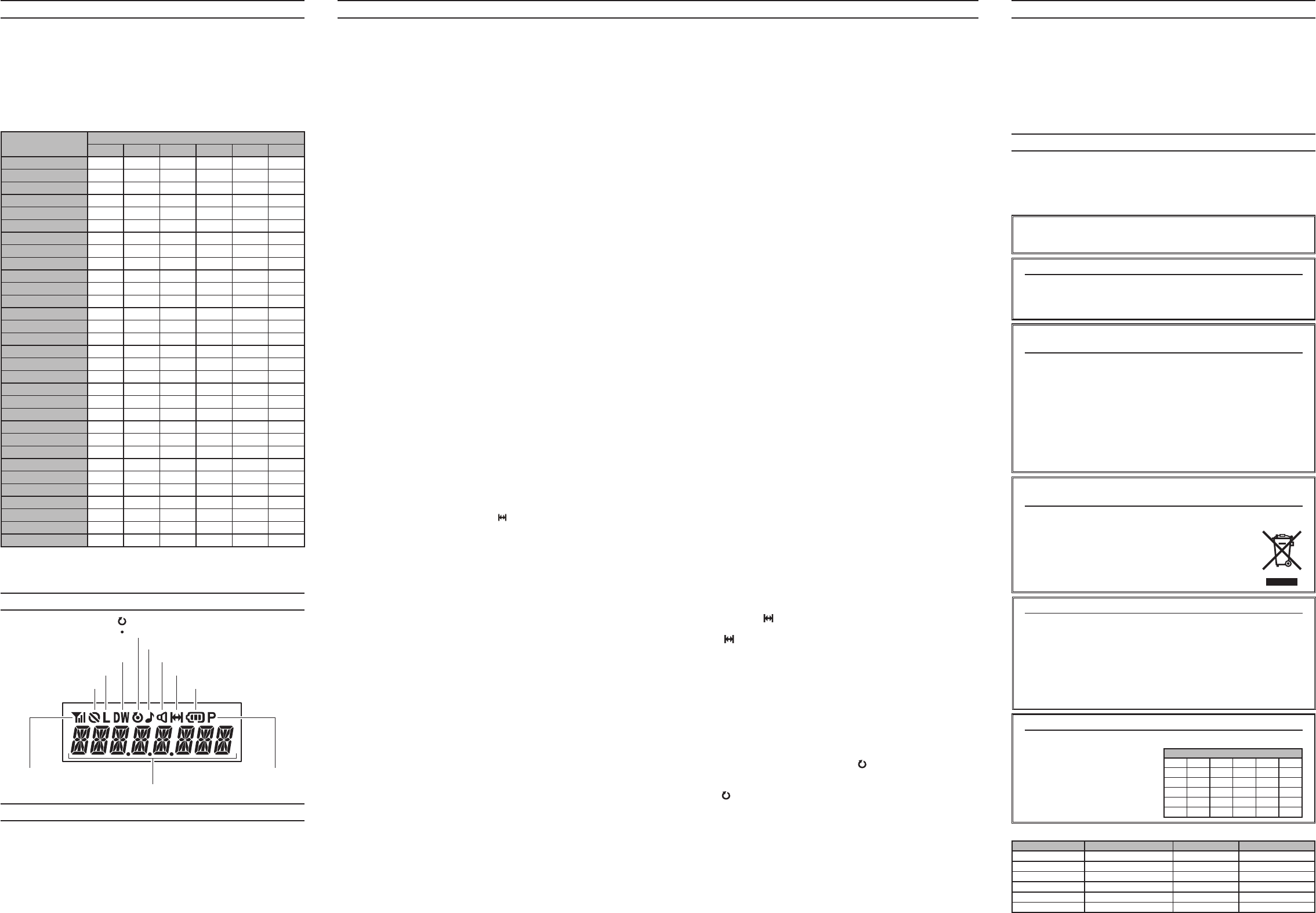
“Talk-Around”isenabled
“DualWatch”isactivated
“Call”Indicator
ReceiverMonitor
LowPowerTransmitMode
8CharacterAlpha-numericDisplay
“Encryption”isenabled
:Thischannelisinthe“Scan”List
:“PriorityScan”isactivated
PriorityChannelindication
BatteryIndicator
RSSIIndicator
Part15.21:Changesormodificationstothisdevicenotexpresslyap-
provedbyVertex Standard couldvoidtheuser’sauthorizationtooperate
thisdevice.
DisplaY iCOns & inDiCatOrs (lCD VersiOn)
Noportionofthismanual
maybereproduced
withoutthepermissionof
VertexStandardLMR,Inc.
Copyright2014
VertexStandardLMR,Inc.
Allrightsreserved.
PrintedinChina
FCC ID: AXI10654620
IC: 10239A-10654620
Vertex Standard LMR, Inc.