Vertex Wireless VW450 GSM/GPRS Terminal User Manual VW450 User s Manual v1 4E
Vertex Wireless Co., Ltd. GSM/GPRS Terminal VW450 User s Manual v1 4E
UserManual.wiki
>
Vertex Wireless
>
VW450 User Manual
User manual
Navigation menu
Upload a User Manual
Namespaces
Wiki Guide
HTML
PDF
Info
Views
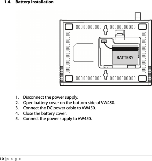
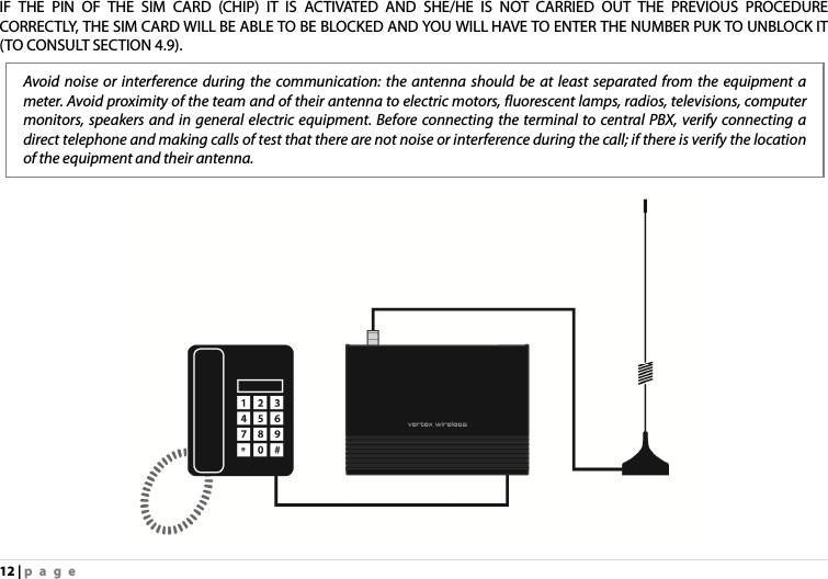
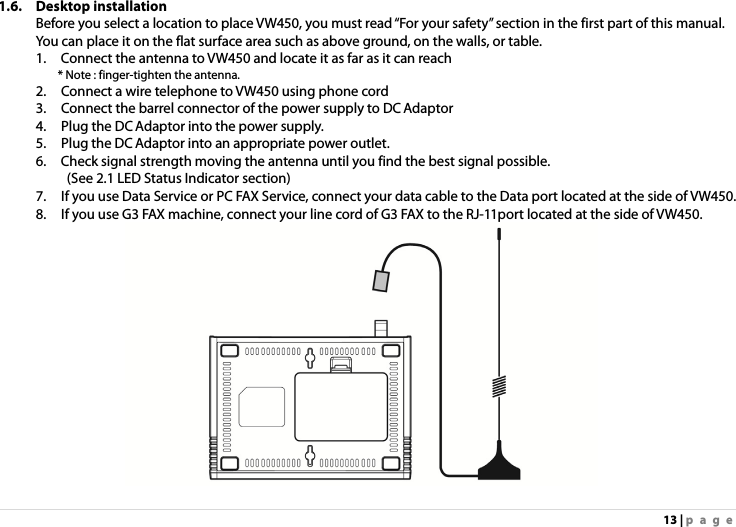
User Manual
Discussion / Help
Navigation