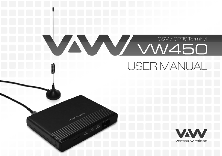
Vertex Wireless VW450 GSM/GPRS Terminal User Manual VW450 User s Manual v1 4E
Vertex Wireless Co., Ltd. GSM/GPRS Terminal VW450 User s Manual v1 4E
User manual
1 | page
V.1.4E

2 | page

3 | page
1. INSTALLATION GUIDE
1.1. FRONT, SIDE AND REAR VIEW OF VW450 07
1.2. CHECKING THE COMPONENTS 08
1.3. SIM CARD INSTALLATION 09
1.4. BATTERY INSTALLATION 10
1.5. INSTALLATION OF THE ANTENNA AND LOCATION OF THE EQUIPMENT FOR VOICE SERVICE 11
1.6. DESKTOP INSTALLATION 13
1.7. WALL MOUNTING 14
2. GETTING TO KNOW VW450
2.1. LED STATUS INDICATOR 15
3. BASIC OPERATIONS
3.1. MAKING CALLS 17
3.2. RECEIVING CALLS 17
4. BASIC SETTINGS
4.1. RECEIVER VOLUME 18
4.2. DIAL DELAY TIME 18
4.3. SPEED DIAL ENTRY 18
4.4. TIME AND DATE 18
4.5. CID FORMAT 19
4.6. BAND SELECTION 19
4.7. EQUIPMENT LOCK 19
4.8. PIN LOCK 20
4.9. POLARITY REVERSE 20
4.10. LOOP CURRENT DISCONNECT 21
4.11. DTMF TONE GENERATION 21

4 | page
4.12. AUTOMATIC PIN ENTERING 21
4.13. FACTORY RESET 21
4.14. VOICEMAIL INDICATION 21
5. SUPPLEMENTARY SERVICE FEATURES
5.1. CALL FORWARDING 22
5.2. CALL BARRING 23
5.3. CALL WAITING 25
5.4. SIM SECURITY CODES 26
5.5. CALLER ID 26
6. DATA SERVICE FEATURES 27
7. FAX SERVICE FEATURE
7.1. ANALOG FAX 27
7.2. DIGITAL FAX 28
8. GENERAL INFORMATION
8.1. SPECIFICATIONS 29
8.2. ADDITIONAL SAFETY INFORMATION 30
8.3. GUARANTEE 32
8.4. TROUBLESHOOTING 33
9. CONFORMANCE STATEMENTS
APPENDIX A 33

5 | page
Welcome to your VW450
VW450 is a Fixed Wireless Terminal designed to provide better wireless connectivity between wire telephone and GSM
850/900/1800/1900 band network with high sensitivity to receive signal and large transmitting power to expand
extensively the effective coverage of GSM service.
Main function & features
- SIMPLE TO INSTALL AND EASY TO MAINTAIN
- COMPATIBLE TO MOST TELEPHONES, PBX
- BATTERY BACK UP DURING AC POWER OUTAGES
- PROVIDE REVERSAL POLARITY SIGNAL FOR METERING
- ADJUSTABLE RECEIVER VOLUME
- 3 LED DISPLAY (SIGNAL/MODE/POWER)
- 10 SPEED DIALS
- CALLER ID DISPLAY
- NETWORK BAND SELECTION
- CALL WAITING/FORWARDING/BARRING
- CONFERENCE CALL
- DATA COMMUNICATION (INTERNET OVER CSD/GPRS, DIGITAL FAX)
- ANALOG FAX (VW450)

6 | page
For your safety
Here is important information for safe and efficient operation.
Please read this information before using your VW450.
For optimal performance, install this indoors. When specially used in an outdoor area, it may not work in below 0℃ or over
50℃.
Install VW450 on hard, flat surface for proper ventilation.
Avoid using VW450 in high temperature or near a source of fire or gas.
Avoid storing VW450 in cold areas.
Do not expose VW450 to moisture or dust.
Do not use VW450 in the hospital. It will interfere with medical electronic equipments such as a peace maker.
Do not use harsh chemicals, cleaning solvents to clean VW450. And wipe with a soft, clean, dry cloth to clean it.
Do not knock, drop, and shake VW450 to avoid breaking the case.
Use only the supplied or approved replacements
Do not use VW450 with a car battery.
Do not touch the antenna when VW450 is being used.
Do not use VW450 with a damaged antenna. Have your antenna replaced by a qualified technician immediately.
Use only the provided antenna. Do not use the provided antenna for any other purpose.
Use only the provided adapter. Do not use the provided adapter for any other purpose
If VW450 fails to work for any reason, do not attempt to disassemble.
7 | page
1. Installation guide
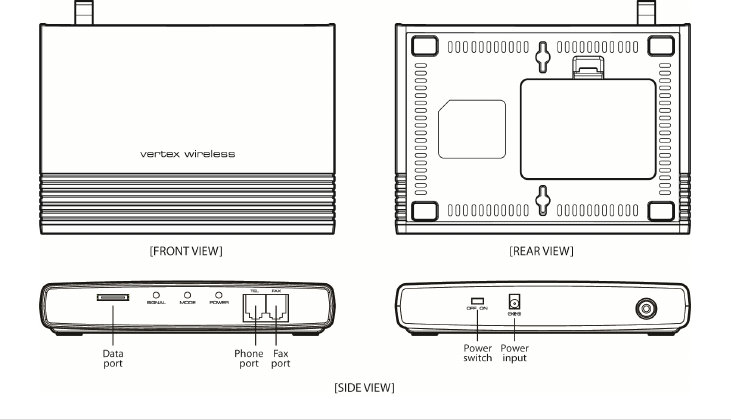
1.1. Front, Side and Rear View of VW450
8 | page
1.2. Checking the components
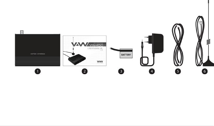
Check to make sure that you have all the parts shown below after opening the package. If any piece is missing or
broken, please call your agent or customer service.
1. MAIN UNIT
2. USER MANUAL
3. LI-ION BACKUP BATTERY
4. DC POWER ADAPTER
5. CABLE FOR GPRS CONNECTION (VW450): OPTIONAL ACCESSORY
6. ANTENNA AND THE CABLE WITH THEIR SUPPORT (YOU SHOULD COUPLE THE ANTENNA IN THEIR SUPPORT)
9 | page
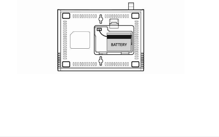
1.3. SIM card installation
1. Disconnect the power supply.
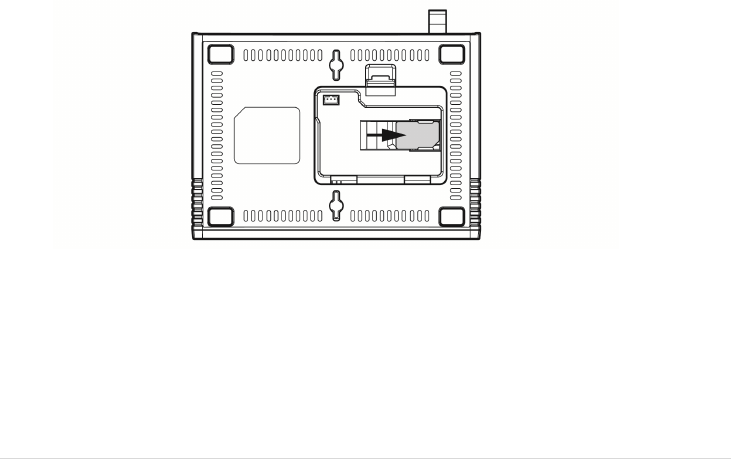
2. Open battery cover on the bottom side of the VW450.
3. Disconnect the DC power cable to VW450
4. Take out the battery pack in the right position between the hold bars
5. Insert the SIM card into the socket as shown in the picture.
* Note: Make sure the SIM card is aligned properly with the directional arrow on the holder.
6. Connect the DC power cable to VW450.
7. Insert the battery pack in the right position between the hold bars.
8. Close the battery cover.
9. Connect the power supply to VW450.
10 | page
1.4. Battery installation
1. Disconnect the power supply.
2. Open battery cover on the bottom side of VW450.
3. Connect the DC power cable to VW450.
4. Close the battery cover.
5. Connect the power supply to VW450.

11 | page
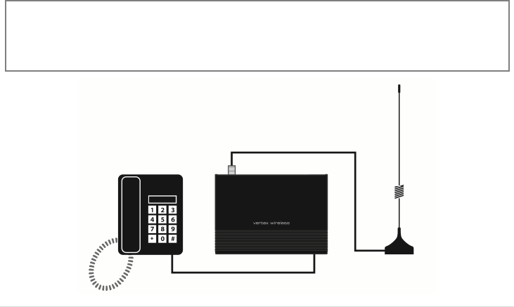
1.5. Installation of the antenna and location of the equipment for voice service
Before you select a localization to place VW450, you should read the section for their Security in the first part of this
manual. You can place it in a plane area just as the floor, the walls or the desk or table.
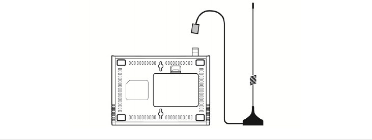
1. It connects the antenna at the VW450 (previously it should couple the antenna in their support, make sure of
making the one it couples in a complete way, verify that the antenna mo is slack) and locate her it more far possible
of the terminal. If the antenna is located near the VW450 noise she/he will take place during the communication,
avoid it!
* Notices: make sure of pressing the antenna completely to their connector in the terminal.
2. Using the marked port as “Phone “connects the VW450 to the central PBX, or to the system of tariff of the booth
or a similar telephone. If their Terminal is model VW450 and you will use similar fax, connect the fax machine to the
port “Fax ".
3. Connect the adapter to the Terminal. Use the connector "DC Input."
4. Connect the adapter DC in an appropriate energy plug.
5. Turn on the terminal. Use the switch “On/Off ".
6. Checks the power of the signal GSM, verify the state of the led “Signal“(check the section 2.1). To improve the
signal reception, move the antenna and verify the state of the led “Signal".
Avoids leaving the antenna in a location in which the led illuminates red or be shut down
7. The terminal is ready to be used.
Attention : If the SIM Card (Chip) that will be used in the terminal has the number disabled PIN (it consults to their
operator), it won't be necessary to make some additional configuration in the VW450; this will be ready for their use.
In case, on the contrary, the SIM Card has the active PIN that same number PIN it will be recorded in the terminal. To
make it, connect a telephone similar to the port “Phone” and dial: #* 110 * 2 * number PIN #
With the previous procedure it will be engraving in the terminal the number PIN. It is this way when the terminal is
out and then lit, it won't be necessary to carry out this procedure again. Although the Terminal remains out a lot of
time, without current and without battery, the PIN that was recorded will always remember.
12 | page
IF THE PIN OF THE SIM CARD (CHIP) IT IS ACTIVATED AND SHE/HE IS NOT CARRIED OUT THE PREVIOUS PROCEDURE
CORRECTLY, THE SIM CARD WILL BE ABLE TO BE BLOCKED AND YOU WILL HAVE TO ENTER THE NUMBER PUK TO UNBLOCK IT
(TO CONSULT SECTION 4.9).
A
void noise or interference during the communication: the antenna should be at least separated from the equipment a
meter. Avoid proximity of the team and of their antenna to electric motors, fluorescent lamps, radios, televisions, computer
monitors, speakers and in general electric equipment. Before connecting the terminal to central PBX, verify connecting a
direct telephone and making calls of test that there are not noise or interference during the call; if there is verify the location
of the equipment and their antenna.
13 | page
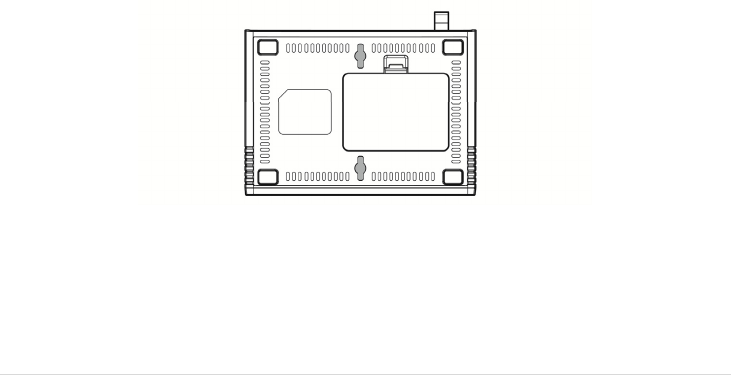
1.6. Desktop installation
Before you select a location to place VW450, you must read “For your safety” section in the first part of this manual.
You can place it on the flat surface area such as above ground, on the walls, or table.
1. Connect the antenna to VW450 and locate it as far as it can reach
* Note : finger-tighten the antenna.
2. Connect a wire telephone to VW450 using phone cord
3. Connect the barrel connector of the power supply to DC Adaptor
4. Plug the DC Adaptor into the power supply.
5. Plug the DC Adaptor into an appropriate power outlet.
6. Check signal strength moving the antenna until you find the best signal possible.
(See 2.1 LED Status Indicator section)
7. If you use Data Service or PC FAX Service, connect your data cable to the Data port located at the side of VW450.
8. If you use G3 FAX machine, connect your line cord of G3 FAX to the RJ-11port located at the side of VW450.
14 | page
1.7. Wall mounting
1. Mark two mounting hole locations to match the screw hole in the back of VW450.
2. Drill two holes at the marked locations.
3. Tighten the screws until the head is about 3~5mm from the wall.
4. Hang VW450 on the screw using the two holes in the back.
5. Push VW450 down until the unit is firmly locked into place.

15 | page
2. Getting To Know VW450
2.1 LED Status Indicator
When your VW450 is powered on, the LED Status Indicators show operation of the indicators and the modes.
When your VW450 is turned on, the LED Status Indicators show operation of power status, signal strength and
current mode.
* Note : If you are getting no service or limited service, contact your service provider.
1) POWER
LED Color Activity Description
Green Continuous Normal
Amber Continuous Charging
Red Continuous Low
Red Flashing Very Low
2) SIGNAL
LED Color Activity Description
Green Continuous High
Amber Continuous Middle
Red Continuous Low
Red Flashing Limited Service
Off Continuous No Service
3) MODE
LED Color Activity Description
Green Continuous Fax/Data Call
Green Flashing Incoming Fax/Data Call
AMBER Continuous Voicemail
Red Continuous Off-Hook or Voice Call
Red Flashing Incoming Voice Call

16 | page
4) EXCEPTION STATUS
LED Activity Description
ALL LED Flashing(Red) then
Mode LED : GREEN Insert SIM
ALL LED Flashing(Red) then
Signal LED : GREEN
Equipment Locked, Enter Lock Code
(See 4.8 Equipment Lock section)
ALL LED Flashing(Red) then
Signal LED : AMBER
PIN Locked, Enter PIN
(See 4.9 PIN Lock section)
ALL LED Flashing(Red) then
Signal LED : RED
PIN Blocked, Enter PUK *
(See 4.9 PIN Lock section)
ALL LED Flashing(Red) then
Mode LED : AMBER MEP Network Locked *
ALL LED Flashing(Red) then
Mode LED : RED AUTO PIN Locked **
ALL LED Flashing(Red) then
Power LED : GREEN Cell Locked *
ALL LED Flashing(Red) then
Power LED : RED MEP SIM Locked *
* Contact your service provider to verify that service has been activated.
** If your service provider use AUTO PIN feature, you must use the SIM card provided from your service provider. If a proper SIM card is installed
and ‘AUTO PIN Locked’ state continues, contact your service provider.

17 | page
3. Basic operations
3.1 Making calls
1. Check to see that your VW450 is turned on.
2. Pick up the handset of the phone.
3. If you listen for dial tone, dial the desired telephone number. The call will be automatically made by VW450.
If you hear fast beep tone, check SIM card or signal strength.
* Note : If you can’t hear dial tone produced, check to make sure that all the parts are properly connected, hang up the phone, and try
again.
If you press ‘Flash key’, or press the switch-hook and release after dialing a number, Call will be made immediately.
When you use telephone, Analog fax connected to fax port can not be used at the same time.
3.2 Receiving calls
1. When the phone rings, pick up the telephone handset, begin to talk.
2. To disconnect after finished, replace the handset on the phone.
* Note : When there is an incoming call when you are already holding the receiver, press ‘Flash key’ to answer the call.
18 | page
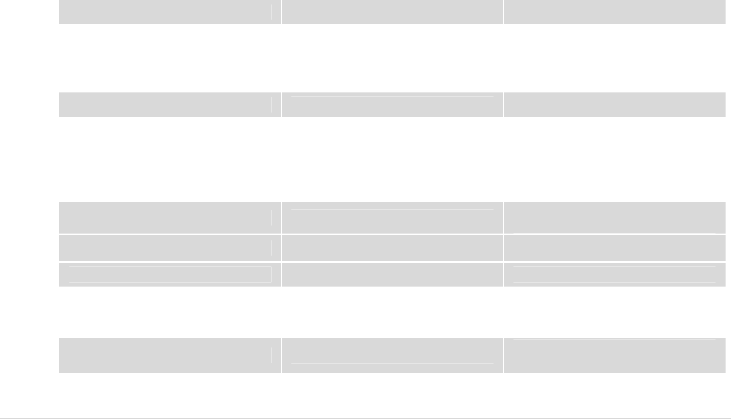
4. Basic Settings
4.1. Receiver Volume
You can control the volume level in the range of 1 to 7 using the keypad on the telephone.
Set Receiver Volume # * 100 * <level> # level : 1 - 7
4.2. Dial Delay Time
You can set dial delay time that your VW450 waits after the phone number is dialed before automatically sending
the number.
Set Dial Delay Time # * 101 * <delay> # delay : 3-20 seconds
The default delay time is 3 seconds.
4.3. Speed Dial Entry
You can store up to 10 frequently used phone numbers in the ‘SIM card’ memory and you can make a call by
pressing record number.
Add/Modify # * 102 * <N> * <NNNN> # N : RECORD NUMBER(0-9)
NNNN : Phone number
Delete # * 103 * <N> # N : RECORD NUMBER(0-9)
Call using speed dial # * <N> # N : RECORD NUMBER(0-9)
4.4. Time and Date
You can set time and date to be displayed on a connected caller ID device.
Set Time # * 104 * <HH><MM> # HH : Hours(24h)
MM : Minutes

19 | page
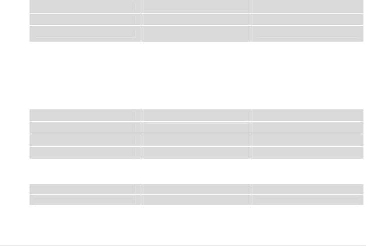
Set Date # * 105 * <MM><DD><YYYY> #
MM : Month
DD : Day
YYYY : Year
For 2:30 PM, press # * 104 * 1430 #
For 31 DEC 2007, press # * 105 * 12312007 #
* Note : This function is dependent on the phone connected to VW450..
4.5. CID Format
You can set CID format that is available on wire phone with CID function.
SDMF format # * 106 * 1 #
MDMF format # * 106 * 2 #
* Note : SDMF stands for Single Data Message Format and MDMF stands for Multiple Data Message Format.
4.6. Band Selection
Your phone supports quad frequency band.( GSM900, DCS1800, GSM850, and PCS1900)
This feature depends on your service provider’s setting.
GSM900/DCS1800 # * 108 * 1 #
GSM850/PCS1900 # * 108 * 2 #
GSM900, DCS1800,
GSM850, PCS1900 # * 108 * 3 #
4.7. Equipment Lock
The lock code prevents VW450 from being used by unauthorized person without your permission. The default lock
code is 0000.
When equipment lock is activated, you must enter lock code using ‘Enter Lock Code’ string every time the VW450 is
turned on. (See 2.1 LED Status Indicator section)
Activate # * 109 * 1 * <password> #
20 | page
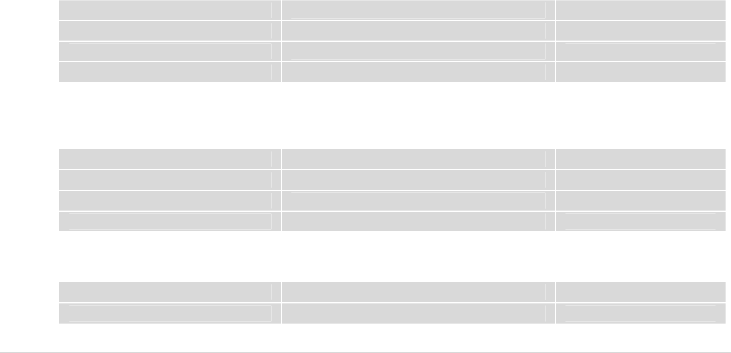
Deactivate # * 109 * 0 * <password> # Default
Enter Lock Code # * 109 * 2 * <password> # password : 4 digits
Change Lock Code # * 109 * 3 * <old password> *
<new password> #
4.8. PIN Lock
The SIM card has a PIN to prevent VW450 from being used by unauthorized person without your permission.
The PIN can be between 4 and 8 digits in length and any combination of digits 0 to 9.
When PIN lock is activated, you must enter the PIN using ‘Enter PIN’ string every time the VW450 is turned on.
You have 3 chances to enter the PIN. If incorrect PIN is entered 3 times consecutively, the SIM card will be locked. To
unlock the phone, you must enter the PUK using ‘Enter PUK’ string.
(See 2.1 LED Status Indicator section)
Activate # * 110 * 1 * PIN #
Deactivate # * 110 * 0 * PIN #
Enter PIN # * 110 * 2 * PIN #
Enter PUK # * 110 * 4 * PUK * New PIN #
4.9. Polarity Reverse
This feature is provided for metering or PBX.
Activate # * 111 * 1 #
Deactivate # * 111 * 0 #
4.10. Loop Current Disconnect
This feature is provided for metering or PBX.

21 | page
Activate # * 112 * 1 #
Deactivate # * 112 * 0 #
4.11. DTMF tone generation
This feature is provided for specific PBX.
By VW450 # * 113 * 1 #
By wire phone # * 113 * 0 # default
4.12. Automatic PIN Entering
You do not need to enter the PIN upon power up if it is stored in VW450 – the PIN is entered automatically. This
function is convenient in case of power failure; VW450 would be operable in a short time after power recovery
without any intervention by the operating staff.
Note : When the Automatic PIN Entering is attempted with the incorrect PIN stored in VW450. The VW450 would make alert signals with
LED(See 2.1 “Exception Status” section). There is the manual PIN-entering way after such unsuccessful automatic entering(See 4.8).
4.13. Reset
This function is used to change the main settings of the terminal back to the default settings, which were
programmed into the terminal at the factory.
Factory Reset # * 119 * <PASSWORD> #
4.14. Voicemail Indication
The VW450 can inform that you received voicemail, using Mode LED (Amber Color).
Activate # * 107 * 1 # DEFAULT
Deactivate # * 107 * 0 #
22 | page
5. Supplementary Service Features
5.1. Call Forwarding
An incoming call can be delivered to another telephone number programmed.
Please contact your service provider for availability.
1) All Calls
You can send all incoming calls to a different number using this feature.
Activate & register number * * 21 * <Number> # Flash
Deactivate & deregister number # # 21 # Flash
Activate * 21 # Flash
Deactivate # 21 # Flash
2) No Answer
When your phone is not answered after certain amount of time, you can send all incoming calls to a different
number.
Activate & register number ** 61 * <Number> * 10 * <Delay> # Flash Delay : 5 – 30 Seconds
Deactivate & deregister number ## 61 # Flash
Activate * 61 * <Number> # Flash
Deactivate # 61 #
3) Unreachable
When your account is not reachable, you can send all incoming calls to a different number.
Activate ** 62 * <Number> # Flash
Deactivate ## 62 # Flash

23 | page
4) Busy
When your account is Busy, You can send all incoming calls to a different number.
Activate * * 67 * <Number> # Flash
Deactivate # # 67 # Flash
5) All Types
To deactivate all type of ‘Call Forwarding’ feature,
Deactivate ## 002 # Flash
5.2. Call Barring
Call Barring is a feature, which the specified numbers cannot be called.
1) Bar all outgoing calls
Does not allow all outgoing calls, but still wish to receive incoming calls at any time.
Activate * 33 * PIN # Flash
Deactivate # 33 * PIN # Flash
2) Bar all outgoing international calls
Does not allow all outgoing international calls to the subscribers of networks outside country you are in. But still
wish to receive incoming calls at any time.
Activate * 331 * PIN # Flash
Deactivate # 331 * PIN # Flash
3) Bar all outgoing international calls when roaming (except to home country)
Does not allow all outgoing calls to countries other than the one where your home network is located.
Activate * 332 * PIN # Flash
Deactivate # 332 * PIN # Flash

24 | page
4) Bar all outgoing calls
Does not allow all outgoing calls, but still wish to receive incoming calls at any time.
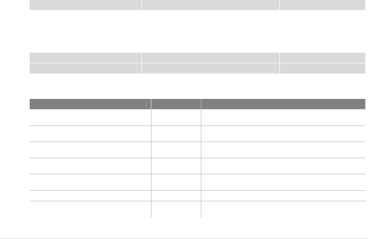
Activate * 333 * PIN # Flash
Deactivate # 333 * PIN # Flash
5) Bar all Incoming Calls
Does not allow all incoming calls but still wish to make outgoing calls at any time.
Activate * 35 * PIN # Flash
Deactivate # 35 * PIN # Flash
6) Bar all incoming calls when international roaming
Does not allow all incoming calls when you are roaming outside the country where your home network is located.
But still wish to make outgoing calls at any time.
Activate * 351 * PIN # Flash
Deactivate # 351 * PIN # Flash
7) Bar all calls
Does not allow all incoming or outgoing calls.
Activate * 350 * PIN # Flash
Deactivate # 350 * PIN # Flash
8) Bar all incoming calls
Does not allow incoming calls but still wish to make outgoing calls at any time.
Activate * 353 * PIN # Flash
Deactivate # 353 * PIN # Flash
25 | page
9) Deactivate all call barring
Deactivate # 330 * PIN # Flash
5.3. Call Waiting
Call Waiting is a feature, which enables you to be alerted to another incoming call while you are on the call of your
telephone.
These features are network-dependent. Contact your service provider to activate or deactivate Call Waiting.
Activate * 43 # Flash
Deactivate # 43 # Flash
The following table describes multiparty call features. These features are handled within an active call. Contact your
service provider for availability.
Feature String Description
Reject call waiting or end call on hold 0 Flash Release all held calls or set User Determined User Busy
for a waiting call
End active call and switch to held or
waiting call 1 Flash Release all active calls and accept the held/waiting call
End a specific call 1<n> Flash n = call number
release a specific active call
Hold active call and retrieve held or
waiting call 2 Flash Place all active calls on hold and accept the held/waiting
call
Hold all active calls and except one 2<n> Flash n = call number
Place all active calls on hold except call <n>
Add held call into active call 3 Flash Add a held call to the conversation
Hold active call and place outgoing call <Number>
Flash
Place all active calls on hold and make a call to a
specified number

26 | page
5.4. SIM Security Codes
The SIM card has a PIN to prevent VW450 from being used by unauthorized person without your permission. You
can set this features and also change SIM card PIN.
Ask your service provider for more information.
Change SIM Card PIN ** 04 * old PIN * new PIN * new PIN #
5.5. Caller ID
1) Incoming (CLIP: Calling Line Identification Presentation)
You can activate the identification information presentation - name and number- of person calling you.
Activate * 30 # Flash
Deactivate # 30 # Flash
2) Outgoing (CLIR : Calling Line Identification Restriction)
You can prevent your identification information from be presentation to person you call.
Activate * 31 # Flash
Deactivate # 31 # Flash
3) Outgoing per-call block
To hide your information for the next call only.
Activate * 31 # <Number> Flash
Deactivate # 31 # <Number> Flash
27 | page
6. Data Service Features
You can send and receive digital fax and access internet if VW450 is connected to the personal computer.
Before you start, Please refer to Appendix A(HOW TO SET UP DATA CONNECTION FOR CSD FAX/DATA AND GPRS DATA)
7. Fax Service Feature
7.1. Analog Fax
1) VW450 supports
- ECM (Error Correction Mode)
- Max 14.4kbps (Local – directly plugged)
- Max 9.6kbps (Network)
- Multiple-page
You can answer faxes through analog fax by setting up the fax-port of VW450 to RJ-11.
And before sending faxes, you need to setup VW450 to fax-mode as below.
Note : When you use analog fax, Telephone connected to telephone port can not be used at the same time.
Feature Mode String Description
Fax Port Selection Serial port(Digital) #* 301 * 0 # Incoming fax call is where to be routed.
RJ-11(Analog) #* 301 * 1 #
Fax National Setup #* 302 * 2 # FAX MACHINE SHOULD BE CONNECTED
Note: Every fax machine has settings to communicate in specific country. If you have a problem of transmission between VW450 and
local fax machine, you can change the national configuration of VW450 by pressing dial #*302*2#. The setting is originally configured

28 | page
by SIM, but after performing this national-setup VW450 will automatically find out the correct setup.
Note: After failure of sending faxes due to network problem or not working fax line, VW450 tries to transmit twice more to designated
fax machine. If the transmission was not successful in spite of 3-tries, you will receive error report.
VW450 also tries to transmit to local fax twice more if failed to transmit faxes successfully got from remote fax machine beyond network.
Note: Maximum amount of pages that VW450 can handle for each transmission is about 500k byte.
7.2. Digital Fax
1) VW450 supports
- Max 9.6kbps
VW450 can be used with any fax-software application on PC. Before using fax capability, you should verify VW450
was plugged in PC. After then choose the right COM-Port for VW450 on your application.
When you answer faxes, you should set up VW450 to digital-mode as below.
Serial port(Digital) #* 301 * 0 #
RJ-11(Analog) #* 301 * 1 #
Note: Every fax specification except max-speed will be taken care of by your fax-software application
(USB data cable needs to be purchased separately)
29 | page
8. General Information
8.1. Specifications
MAIN UNIT
Item VW450
Frequency range GSM850, GSM900, DCS1800, PCS1900
Protocol GSM , GPRS Class B
Multi connection 5 REN
Connection port RJ11 port(For Phone/Fax), Serial port(Data/Fax)
Size(mm) 158X112X26.4
Weight About 268g with a standard battery
Working condition
Environment temperature: -10℃ ~ 50℃
Relative humidity : 10~95%
Air pressure : 86~106kpa
AC/DC ADAPTER
Item VW450
Input voltage AC100-240V
Input F r eq uen cy 50/60Hz
output voltage 5V 1A
INTERNAL BACK-UP BATTERY
Item VW450
Capacity Li-ion battery 3.7V, 1000mAh

30 | page
8.2. Additional Safety Information
For further assistance, contact your Authorized Distributor for service and assistance. Please keep your Model
number and Serial number ready for quicker service.
EVERYDAY USE OF YOUR VW450
Do not touch the antenna unnecessarily when your VW450 is in use, as this will affect call quality and may cause
VW450 to operate at a higher power level than otherwise needed.
As with any other radio transmitting equipment, you are advised that for the satisfactory operation of your VW450
and for your own safety, you should use your VW450 only in the normal operating position.
NON-IONIZING RADIATION (EXPOSURE TO RADIO FREQUENCY SIGNALS)
Your VW450 is a low power radio transmitter and receiver. When it is on, it receives and also sends the radio
frequency(RF) signals. Most modern electronic equipment is shielded from RF signals. However, certain electronic
equipment may not be shielded against the RF signals from your VW450. RF signals may affect improperly installed
or inadequately shielded electronic systems in motor vehicles. Consult your vehicle manufacturer and the
manufacturer of any equipment that has been added to the vehicle.
PAC EMAKERS
The Health industry Manufacturers Association recommends that a minimum separation of six inches be maintained
between VW450 and a pacemaker to avoid potential interference with the pacemaker. Users with pacemakers:
Always keep your VW450 at least 20 cm (6inches) from your pacemakers when the VW450 is switched on.
Switch off your VW450 immediately if you suspect that interference is being caused.
OTHER MEDICAL DEVICES
If you use any other medical devices, please consult a physician or the manufacturer of the medical devices to
determine if they are adequately shielded from external RF energy. Your physician may be able to assist you in
obtaining this information. Always check the regulations of the healthcare facilities, which generally request that
VW450 is switched off .

31 | page
OPERATING ENVIRONMENT
Remember to follow any special regulations in force in any area, and always turn off your VW450 wherever it is
forbidden to use it, or when it may cause interference or danger.
EXPLOSIVE ATMOSPHERES AND MATERIALS
Turn your VW450 off and do not remove the battery when in any area with a potential explosive atmosphere and
obey all signs and instructions. You must observe restrictions on the use of radio equipment in fuel depots; below
deck on boats; fuel or chemical transfer or storage facilities; areas where the air contains chemicals or particles, such
as grain, dust, or metal powders; areas with signs about explosive atmospheres or where blasting operations are in
progress; any other areas where you would normally be advised to turn off your vehicle engines.
BATTERY CHARGING
Do not charge VW450 without the battery in place.
Please use only approved batteries and chargers.

32 | page
8.3. Guarantee
Limited guarantee for the products of personal communication, accessories and software.
8.4. Troubleshooting
Item Remedy
No power Check the power adaptor connection
Check for the appropriate service indication on the LED.
Telephone service is not Working
Make sure VW450 powered on properly.
Check any equipment connected to the VW450 is correctly connected.
Make sure your service is established with a service provider.
Call can not be received.
Check the appropriate power indication on the LED
Check signal strength.
Make sure handset is placed on the cradle
Call can not be made. Make sure your service is established with a service provider.
Check any equipment connected to the VW450 is correctly connected.
Adequate signal is not present Try different locations for the better signal reception.
Analog fax calls isn’t sent or
received
Check the appropriate power indication on the LED
Check the cable is correctly connected to the VW450
GPRS service isn’t Connected. Check the cable connection
Contact the GPRS service provider whether you have service on the account.

33 | page
9. Conformance Statements
APPENDIX A:
HOW TO SET UP DATA CONNECTION FOR CIRCUIT SWITCHED DIGITAL FAX/DATA AND GPRS DATA
FOR THE DATA CONNECTION, BELOW REQUIREMENTS ARE NEEDED.
- SIM CARD FROM YOUR NETWORK SERVICE PROVIDER FEATURING CSD OR GPRS .
- PC OR LAPTOP WITH USB PORT
- WINDOWS 2K OR LATER VERSION
- USB DATA CABLE(USB DATA CABLE NEEDS TO BE PURCHASED SEPARATELY)
- MODEM SETUP WIZARD CD(IT IS SUPPLIED TOGETHER WITH USB DATA CABLE.)
IF YOU USE VERTEX WIRELESS MODEM SETUP WIZARD, DATA CONNECTION WILL BE EASILY SET UP.
NOTE : THIS MANUAL IS FOR WINDOWS XP. SETTING IN OTHER WINDOWS VERSIONS IS SIMILAR.
WHEN YOU WANT THE CSD (DIAL-UP) DATA CONNECTION,
YOU CAN FIND USERNAME, PASSWORD, DIAL NUMBER FROM THE INTERNET ACCESS KIT THAT YOU PURCHASED. AFTER
FILLING THOSE VALUES, PRESS THE DIAL BUTTON.
WHEN YOU WANT THE GPRS DATA CONNECTION,
IF YOUR NETWORK SERVICE PROVIDER HAS THE RECOMMEND SETTING OR THE ACCESS PROGRAM, YOU SHOULD USE
THAT.
IF NOT, YOU DON’T NEED TO INPUT USERNAME, PASSWORD. JUST INPUT A DIAL NUMBER AS “*99#”. AND PRESS THE
DIAL BUTTON.
(USB data cable needs to be purchased separately)

34 | page
FCC ID: XAVVW450
Warning: Exposure to Radio Frequency Radiation The radiated output power of this device is far below the
FCC radio frequency exposure limits. Nevertheless, the device should be used in such a manner that the
potential for human contact during normal operation is minimized. In order to avoid the possibility of
exceeding the FCC radio frequency exposure limits, human proximity to the antenna should not be less
than 100 cm during normal operation. The gain of the antenna for Cellular band must not exceed 3.5 dBi.
The gain of the antenna for PCS band must not exceed 3.1 dBi.
FCC Compliance Information
NOTE: This equipment has been tested and found to comply with the limits for a Class B digital device, pursuant to part 15 of
the FCC Rules.
These limits are designed to provide reasonable protection against harmful interference in a residential installation. This
equipment generates, uses and can radiate radio frequency energy and, if not installed and used in accordance with the
instructions, may cause harmful interference to radio communications. However, there is no guarantee that interference will
not occur in a particular installation. If this equipment does cause harmful interference to radio or television reception, which
can be determined by turning the equipment off and on, the user is encouraged to try to correct the interference by one or
more of the following measures:
- Reorient or relocate the receiving antenna.
- Increase the separation between the equipment and receiver.
- Connect the equipment into an outlet on a circuit different from that to which the receiver is connected.
- Consult the dealer or an experienced radio/TV technician for help.
Caution the user that changes or modifications not expressly approved by the party responsible for compliance could void
the user’s authority to operate the equipment.

35 | page