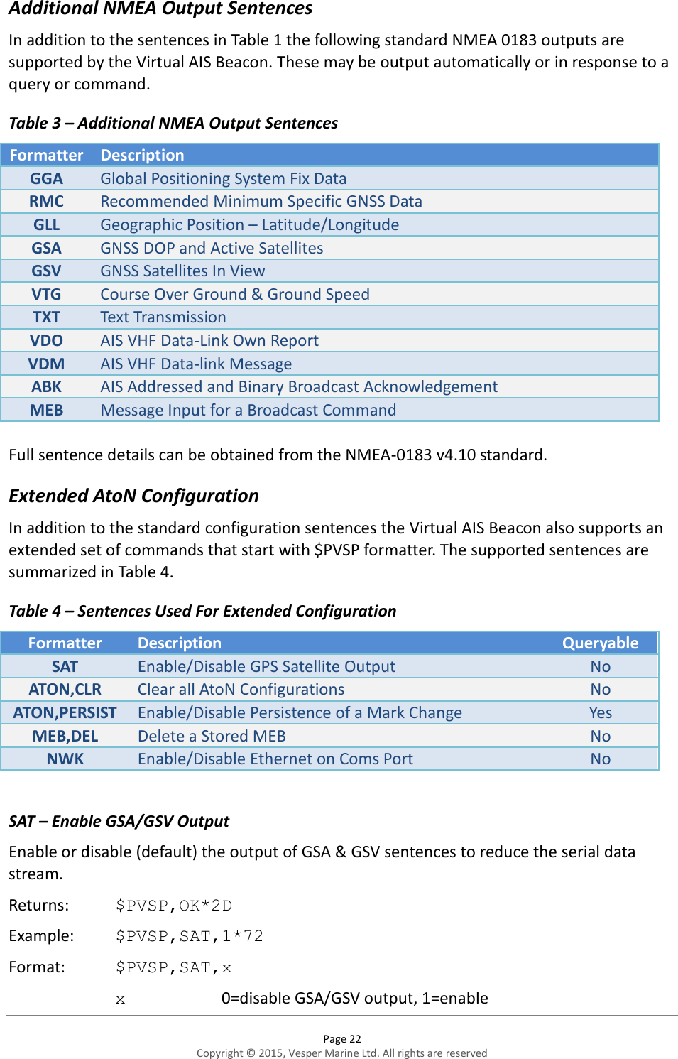
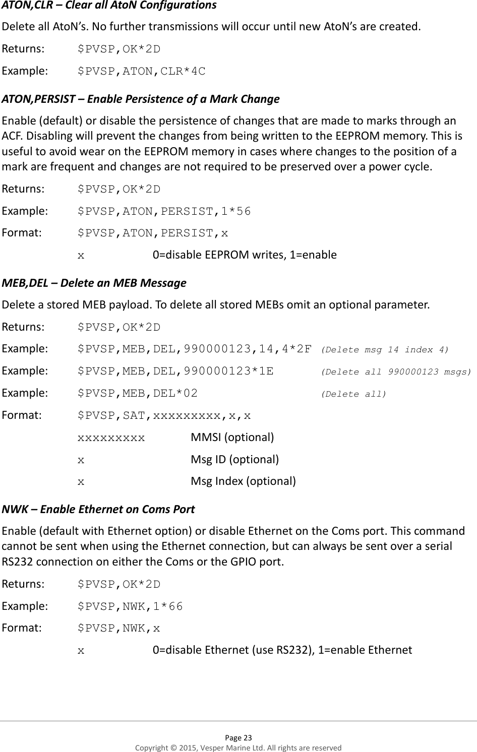
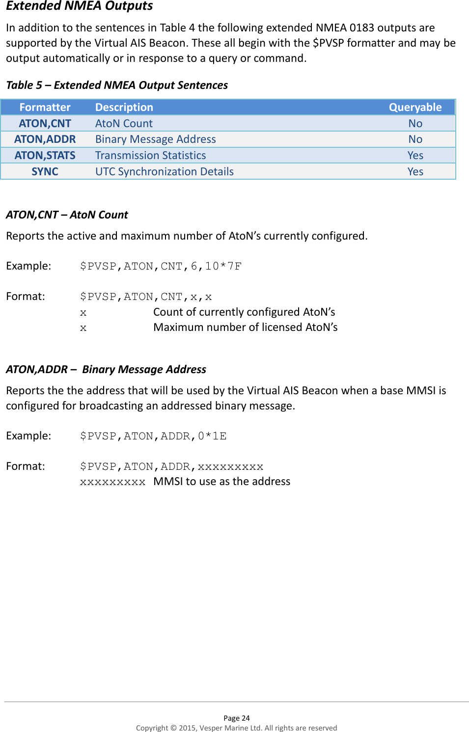
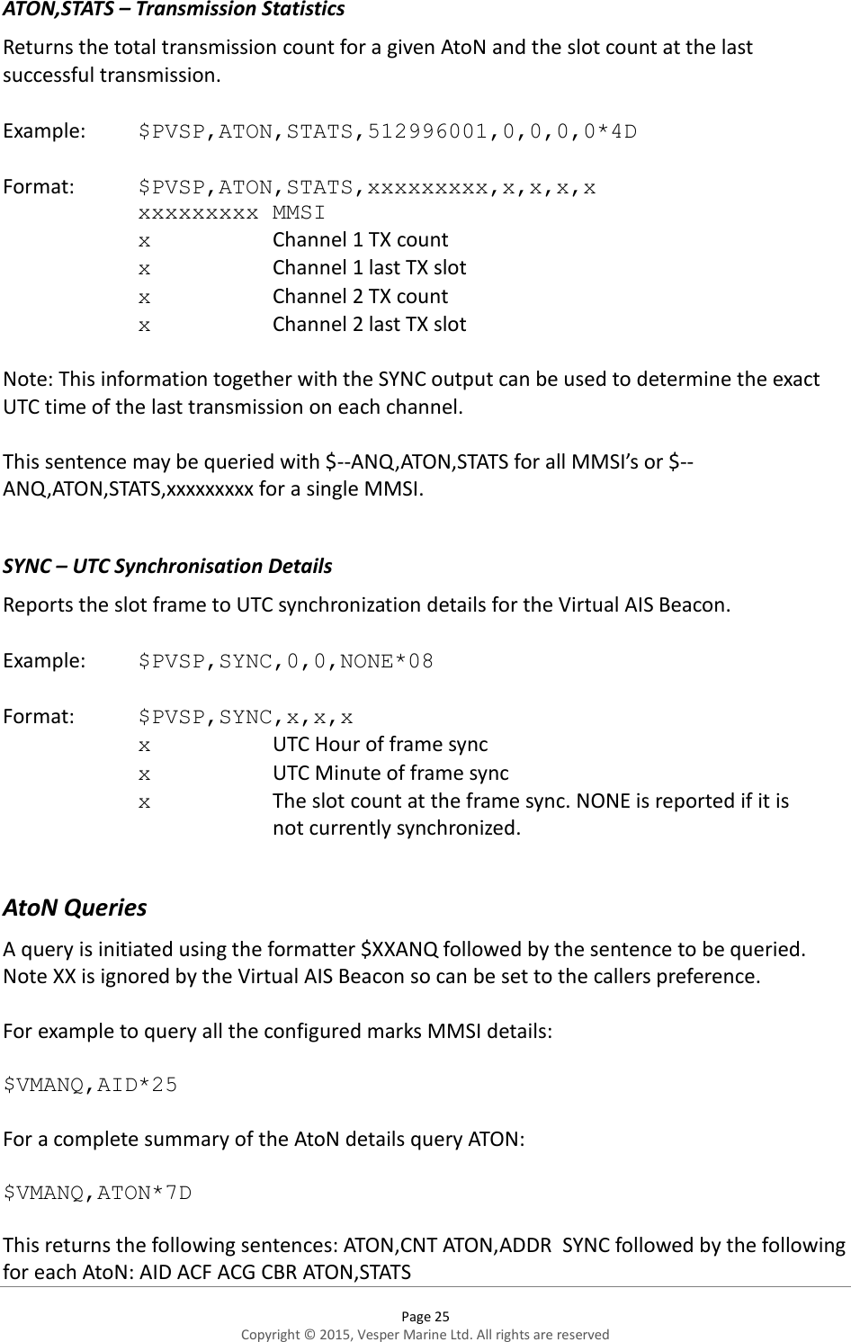
Vesper Marine VESPVAB125 AIS AtoN (Aids-to-Navigation) User Manual
Vesper Marine Limited AIS AtoN (Aids-to-Navigation)
UserManual.wiki
>
Vesper Marine
>
VESPVAB125 User Manual
User manual
Navigation menu
Upload a User Manual
Namespaces
Wiki Guide
HTML
PDF
Info
Views
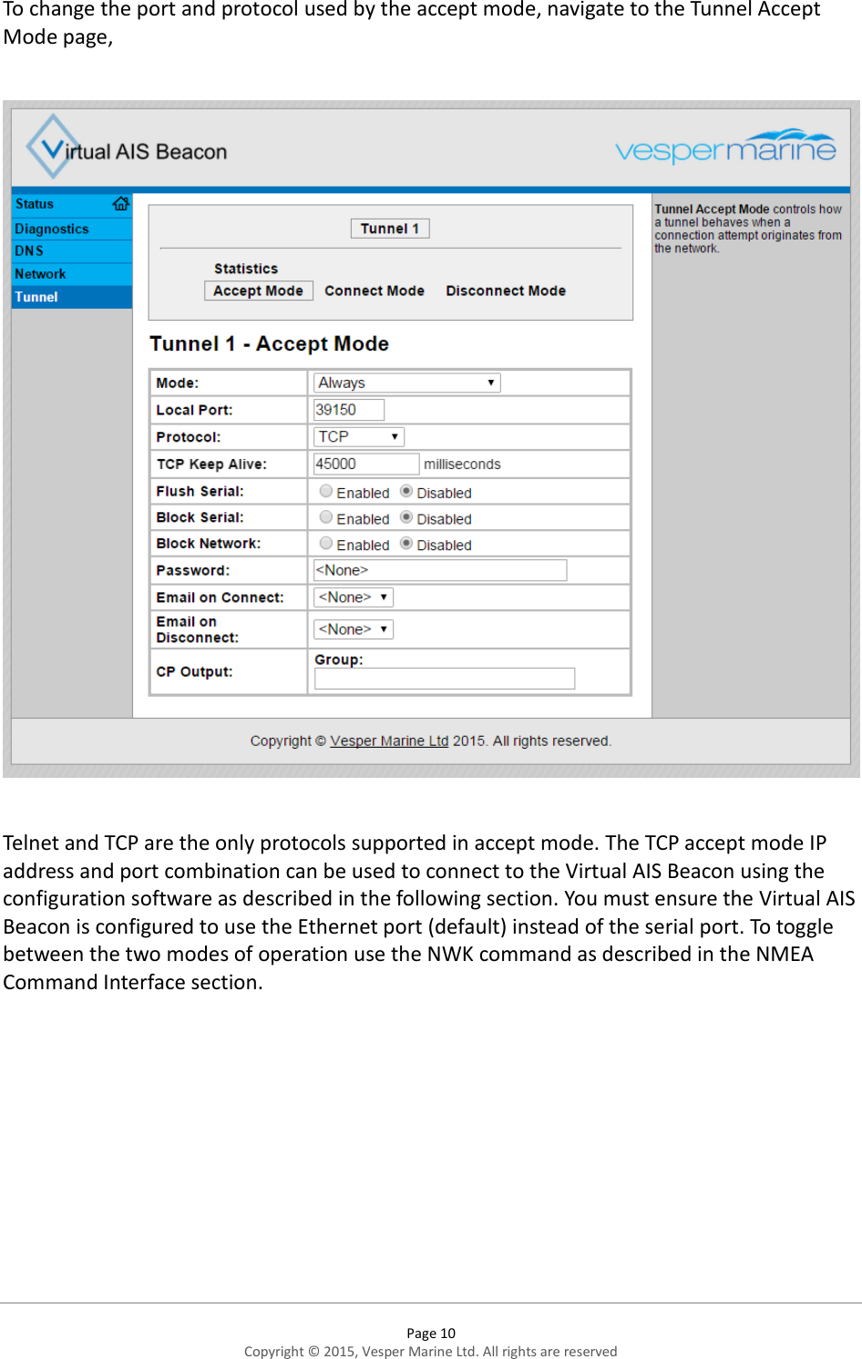
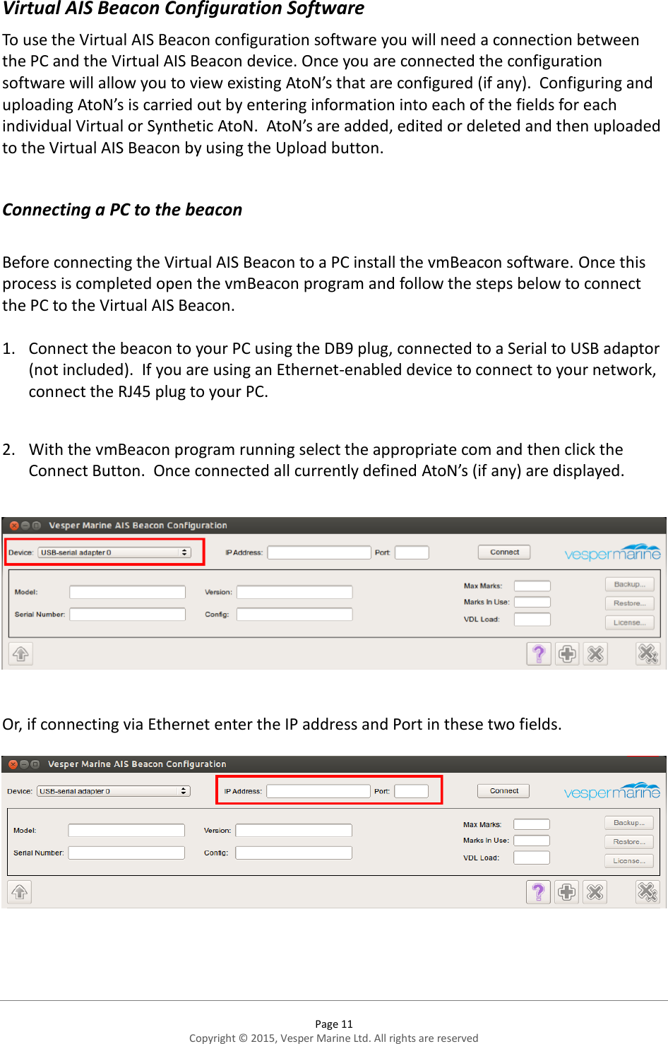
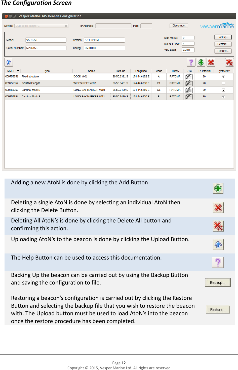
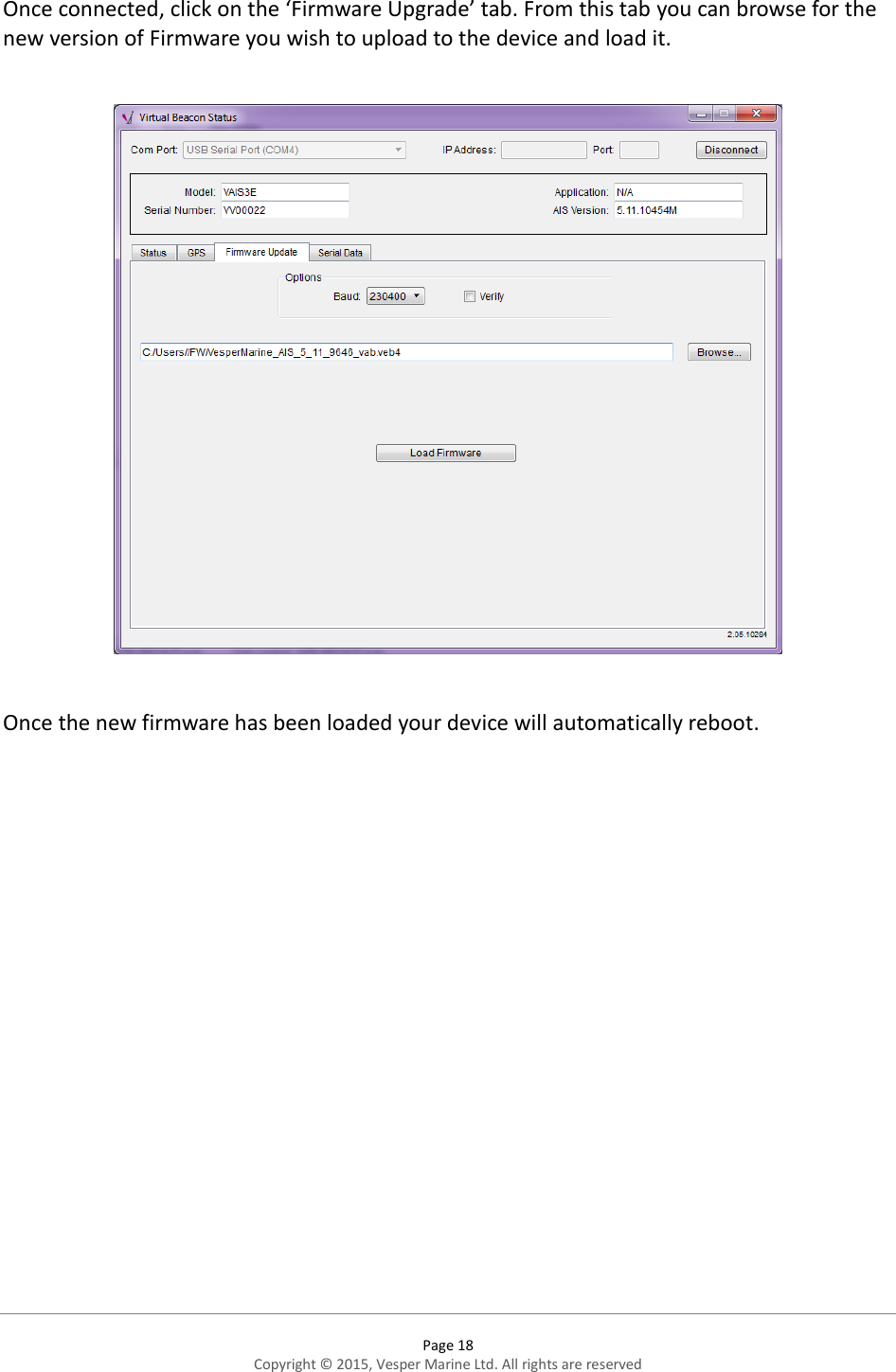
User Manual
Discussion / Help
Navigation