Vesper Marine VESPVAB125 AIS AtoN (Aids-to-Navigation) User Manual
Vesper Marine Limited AIS AtoN (Aids-to-Navigation)
User manual
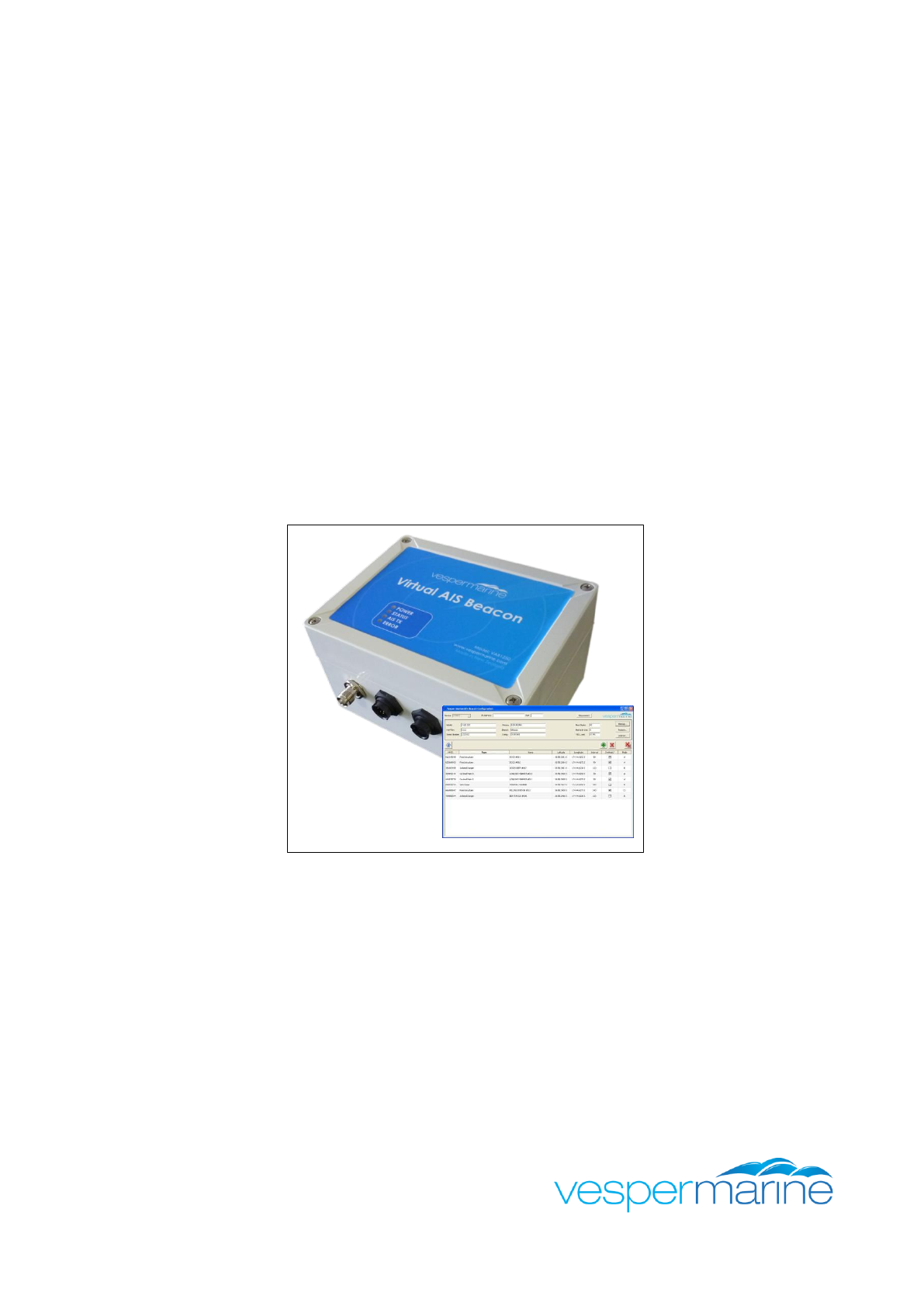
Virtual AIS Beacon
Model: VAB1252
Installation & Configuration Guide

Page 2
Copyright © 2015, Vesper Marine Ltd. All rights are reserved
Important Information ........................................................................................................... 4
Warnings and Cautions .......................................................................................................... 4
Introduction ........................................................................................................................... 4
Regulatory Requirements .................................................................................................. 4
Installation and Wiring ........................................................................................................... 5
Virtual AIS Beacon Connectors and Wiring ........................................................................ 5
VHF Antenna Connection (SO239) ........................................................................................................... 5
GPS Antenna Connection (TNC) ............................................................................................................... 6
Coms Connection (10 Pin) ........................................................................................................................ 6
Power Connection (2 Pin) ......................................................................................................................... 7
Mounting the Virtual AIS Beacon ....................................................................................... 7
LED Status Lights ................................................................................................................ 8
Ethernet Connection .......................................................................................................... 9
Virtual AIS Beacon Configuration Software ......................................................................... 11
Connecting a PC to the beacon ........................................................................................ 11
The Configuration Screen ................................................................................................. 12
Configuration Software Field Descriptions: ..................................................................... 13
Virtual AIS Beacon Firmware Upgrades ............................................................................... 17
NMEA Command Interface .................................................................................................. 19
AtoN Configuration .......................................................................................................... 19
Table 1 – Supported Public NMEA 0183 Sentences ............................................................................... 19
Example Configuration for a Virtual AtoN ........................................................................ 19
Valid AtoN Types .............................................................................................................. 20
Table 2 – Valid AtoN Types ..................................................................................................................... 20
Example Binary Broadcast of an Area Special Message .................................................. 21
Decoded Area Special Message .............................................................................................................. 21
Additional NMEA Output Sentences ................................................................................ 22
Table 3 – Additional NMEA Output Sentences ....................................................................................... 22
Extended AtoN Configuration .......................................................................................... 22
Table 4 – Sentences Used For Extended Configuration ......................................................................... 22
SAT – Enable GSA/GSV Output ............................................................................................................... 22
ATON,CLR – Clear all AtoN Configurations ............................................................................................. 23
ATON,PERSIST – Enable Persistence of a Mark Change ......................................................................... 23
MEB,DEL – Delete an MEB Message ...................................................................................................... 23
NWK – Enable Ethernet on Coms Port ................................................................................................... 23
Extended NMEA Outputs ................................................................................................. 24
Table 5 – Extended NMEA Output Sentences ........................................................................................ 24
ATON,CNT – AtoN Count ........................................................................................................................ 24
ATON,ADDR – Binary Message Address ................................................................................................ 24
ATON,STATS – Transmission Statistics ................................................................................................... 25
SYNC – UTC Synchronisation Details ...................................................................................................... 25
AtoN Queries .................................................................................................................... 25

Page 3
Copyright © 2015, Vesper Marine Ltd. All rights are reserved
Technical Information .......................................................................................................... 26
System Specifications ....................................................................................................... 26
Technical Accuracy ............................................................................................................... 27
General Warnings ................................................................................................................. 27
Obtaining Warranty Service ................................................................................................. 28
Declaration of Conformity ...................................................................................................................... 29
Electronic Waste Recycling..................................................................................................................... 29
Copyright Notice ..................................................................................................................................... 29

Page 4
Copyright © 2015, Vesper Marine Ltd. All rights are reserved
Important Information
Before installing the Virtual AIS Beacon, it is important that you read and fully understand
this guide.
Warnings and Cautions
CAUTION: Never operate this device unless it is connected to a suitable VHF antenna.
Transmitting without an antenna may damage this device.
WARNING: Changes or modifications not expressly approved by Vesper Marine could void
the user’s authority to operate this equipment.
CAUTION: This device generates and radiates electromagnetic energy. This device must be
installed and operated according to the instructions contained in this manual. Failure to do
so may result in product malfunction and / or exposure to potentially harmful levels of radio
frequency radiation.
CAUTION: The system has a Maximum Permissible Exposure (MPE) radius of 1m from the
antenna. This has been determined assuming the maximum power of the transmitter and
using a standard half-wave monopole VHF antenna with a maximum gain of 3dBi and
termination impedance of 50 ohms.
When installing the antenna and operating the equipment consider the following:
The antenna should be mounted as high as possible.
Higher gain VHF antennas will require a larger MPE radius.
Do not operate the unit when anyone is within the MPE radius of the antenna.
The VHF antenna should not be collocated or operated in conjunction with any other
transmitting antenna.
Introduction
The Virtual AIS Beacon is a system which transmits information to assist in marking Aids to
Navigation (AtoN) at sea. It works by transmitting data as part of the Universal Ship borne
Automated Identification Systems (AIS).
Regulatory Requirements
MMSI (Maritime Mobile Service Identity):
At least one MMSI (Maritime Mobile Service Identity) is required for the Virtual AIS Beacon
to begin transmission of an Aid to Navigation (AtoN). MMSI numbers are allocated by the
maritime authority responsible for marine radio spectrum in your region.
Each AtoN you intend to transmit requires a unique MMSI.
VHF radio license:
Various countries have regulations requiring a VHF radio license to operate an AIS
transceiver. Check with your local authorities to determine the requirements for your area.
Page 5
Copyright © 2015, Vesper Marine Ltd. All rights are reserved
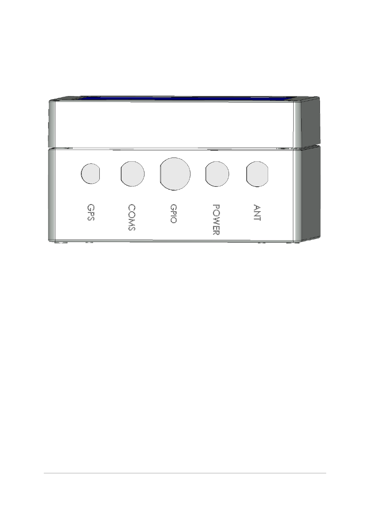
Installation and Wiring
Virtual AIS Beacon Connectors and Wiring
VHF Antenna Connection (SO239)
The Virtual AIS Beacon must be connected to a suitable VHF antenna either sourced from
Vesper Marine or your local marine equipment supplier.
Ensure a VHF antenna is connected to the Virtual AIS Beacon before power is applied to the
beacon.
The performance of the VHF antenna is also highly dependent on the environment in which
the device is mounted. When installing the VHF antenna please take into consideration:
Place your antenna as high as possible and at least 2-3 metres (6-10 ft) above the
water surface.
Place your VHF antenna as far as possible from other antennas and metal structures,
especially other VHF, HF and radar antennas. It is not recommended to place the VHF
antenna directly alongside another VHF antenna.
The type of antenna should be an omnidirectional VHF antenna designed for the
marine band (156-162 MHz).
Ideally an AIS-frequency adapted antenna should be used however you may also use
a standard marine VHF antenna.
Page 6
Copyright © 2015, Vesper Marine Ltd. All rights are reserved
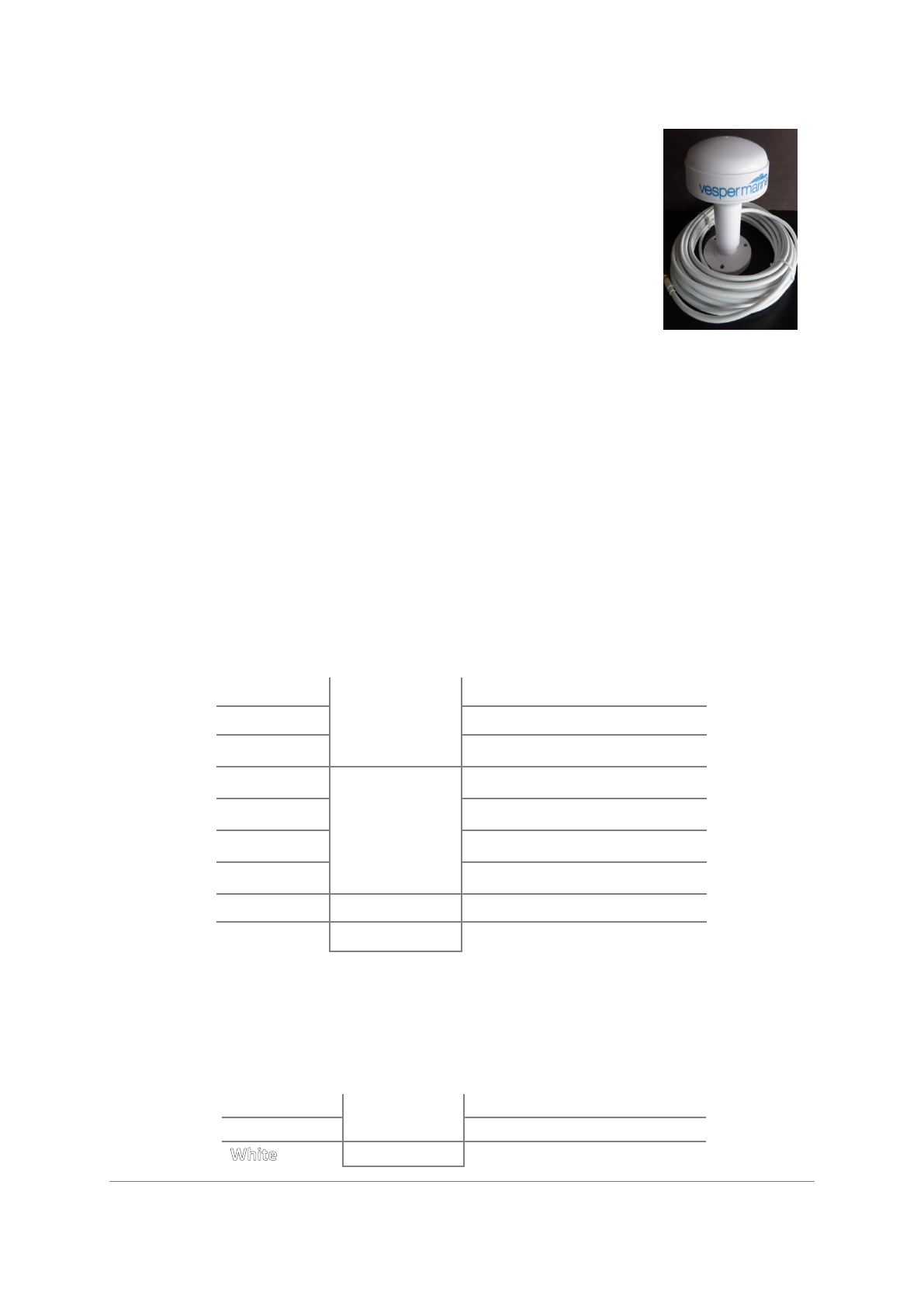
GPS Antenna Connection (TNC)
The Virtual AIS Beacon is provided with an external GPS antenna. This
antenna requires an unobstructed view of the sky. You cannot share
this GPS antenna with other equipment.
The performance of the GPS antenna is highly dependent on the
environment in which the antenna is mounted. The antenna
performance may be reduced if the antenna is under or near large
metal structures.
When installing the external GPS antenna please take into
consideration:
Ensure the antenna connector is isolated from metal at all times.
Do not place the GPS antenna near or in the path of radar or HF antennas.
The GPS antenna should be situated so it has an unobstructed view of the sky above.
Any damage caused by using an incompatible GPS antenna is not covered under your
warranty.
Coms Connection (10 Pin)
A 2m (6.5') data cable with a female DB9 plug is supplied with the Virtual AIS Beacon to
connect to the Coms Port. An additional 2m (6.5’) Ethernet cable with RJ45 plugs is provided
to support network connectivity for Ethernet-enabled devices. You may extend these cables
as necessary. Firmware upgrades can be carried out using this port. The data cable color
code is as follows,
Yellow
Com Port
(RS232)
RS232 Common
Green
RS232 data in
Gray
RS232 data out
Brown
Com Port
(Ethernet)
Ethernet TX+
Blue
Ethernet TX-
Black
Ethernet RX+
Orange
Ethernet RX-
Red
Do Not Connect (recovery)
Pink
Do Not Connect (recovery)
GPIO Connection (16 Pin)
A 2m (6.5') cable with bare wire leads is supplied with the Virtual AIS Beacon to connect to
the GPIO Port. You may extend this cable as necessary. The GPIO cable color code is as
follows,
Blue
GPIO Port
RS232 data in
Brown
RS232 data out
RS232 Common
Page 7
Copyright © 2015, Vesper Marine Ltd. All rights are reserved
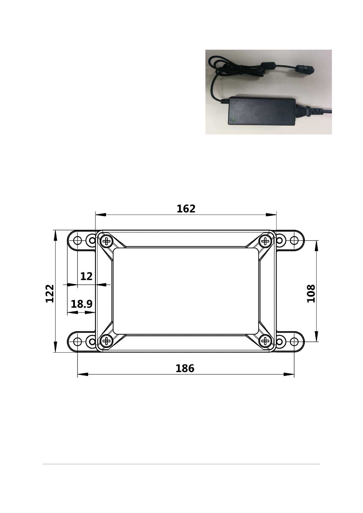
Power Connection (2 Pin)
The Virtual AIS Beacon has a 2 pin plug for 12 VDC,
peak 4.5A, nominal 0.25A.
Depending on shipping destination a short circuit
protected and isolated ground 12VDC 5A AC/DC
power pack with a regional IEC power cable may also
be supplied.
Mounting the Virtual AIS Beacon
The Virtual AIS Beacon has footprint dimensions as detailed below and a height of 90mm.
The device is mounted by using the fixing lugs. Drill holes in the mounting surface using the
lugs as a guide. Fasten with appropriate length screws.
Caution: Do not disassemble the unit or remove the screws which hold the Virtual AIS
Beacon together. The unit is sealed and disassembly will void the warranty. If you require
service or assistance please contact Vesper Marine.

Page 8
Copyright © 2015, Vesper Marine Ltd. All rights are reserved
LED Status Lights
Once the VHF antenna, GPS antenna and the power is connected the
Virtual AIS Beacon can be turned on. The LED lights on the front panel
have the following states:
POWER
Green: The Virtual AIS Beacon has power.
GPS STATUS
Blue Flashing: GPS acquiring a fix and/or sync to UTC time (can take up to
12mins to get a sync)
Blue: GPS fixed and synchronized to UTC time
TRANSMIT
Green Flash: On an AIS transmission.
Red: Built in integrity check error. Typically this would indicate a bad
antenna connection.
NETWORK
Orange: Link established.
Green Flashing: Network connection active.
(optional – only applies to Ethernet enabled devices)
Page 9
Copyright © 2015, Vesper Marine Ltd. All rights are reserved
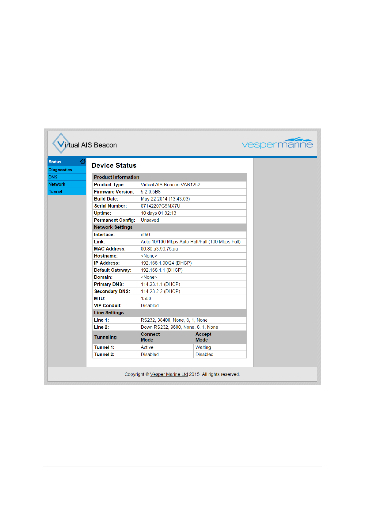
Ethernet Connection
An Ethernet enabled (optional) Virtual AIS Beacon is configured to both automatically
connect to a Vesper Marine secure server and to accept an incoming TCP connection on port
39150. It will use DHCP by default, so once connected to your network it will be
automatically assigned an IP address. Once the IP address is found (by a network query or by
checking your router address table) its status can be queried on port 80 using an internet
browser. On a successful connection you will see the following web page,
Page 10
Copyright © 2015, Vesper Marine Ltd. All rights are reserved
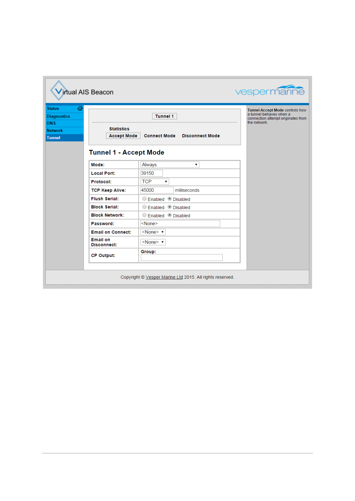
To change the port and protocol used by the accept mode, navigate to the Tunnel Accept
Mode page,
Telnet and TCP are the only protocols supported in accept mode. The TCP accept mode IP
address and port combination can be used to connect to the Virtual AIS Beacon using the
configuration software as described in the following section. You must ensure the Virtual AIS
Beacon is configured to use the Ethernet port (default) instead of the serial port. To toggle
between the two modes of operation use the NWK command as described in the NMEA
Command Interface section.
Page 11
Copyright © 2015, Vesper Marine Ltd. All rights are reserved
Virtual AIS Beacon Configuration Software
To use the Virtual AIS Beacon configuration software you will need a connection between
the PC and the Virtual AIS Beacon device. Once you are connected the configuration
software will allow you to view existing AtoN’s that are configured (if any). Configuring and
uploading AtoN’s is carried out by entering information into each of the fields for each
individual Virtual or Synthetic AtoN. AtoN’s are added, edited or deleted and then uploaded
to the Virtual AIS Beacon by using the Upload button.
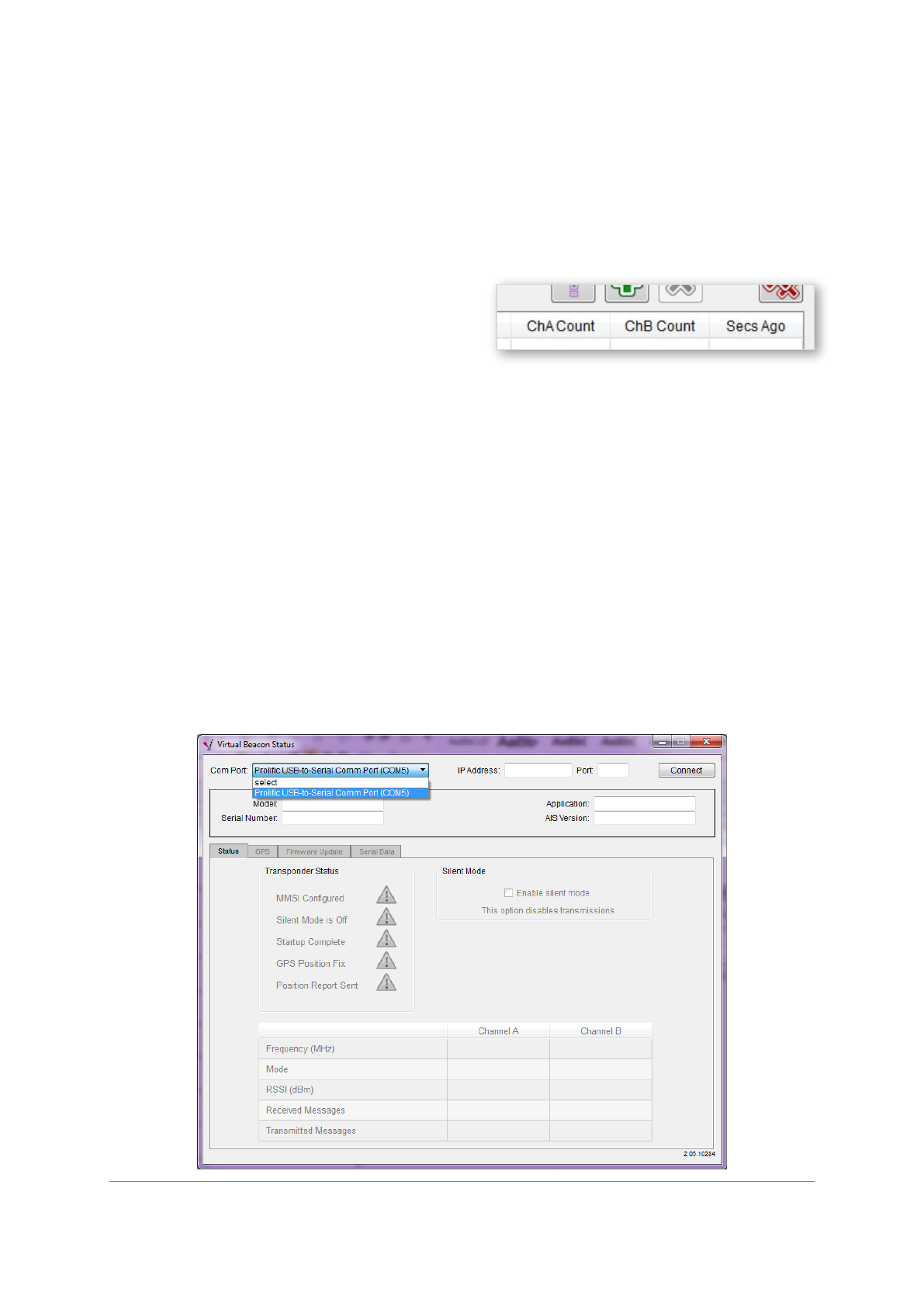
Connecting a PC to the beacon
Before connecting the Virtual AIS Beacon to a PC install the vmBeacon software. Once this
process is completed open the vmBeacon program and follow the steps below to connect
the PC to the Virtual AIS Beacon.
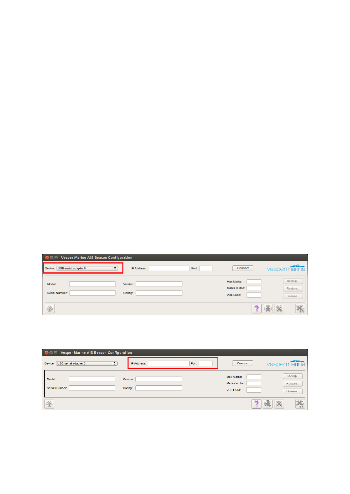
1. Connect the beacon to your PC using the DB9 plug, connected to a Serial to USB adaptor
(not included). If you are using an Ethernet-enabled device to connect to your network,
connect the RJ45 plug to your PC.
2. With the vmBeacon program running select the appropriate com and then click the
Connect Button. Once connected all currently defined AtoN’s (if any) are displayed.
Or, if connecting via Ethernet enter the IP address and Port in these two fields.
Page 12
Copyright © 2015, Vesper Marine Ltd. All rights are reserved
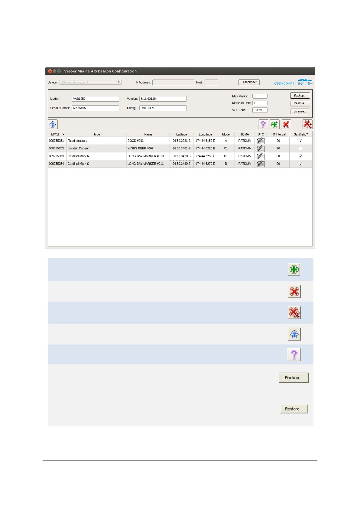
The Configuration Screen
Adding a new AtoN is done by clicking the Add Button.
Deleting a single AtoN is done by selecting an individual AtoN then
clicking the Delete Button.
Deleting All AtoN’s is done by clicking the Delete All button and
confirming this action.
Uploading AtoN’s to the beacon is done by clicking the Upload Button.
The Help Button can be used to access this documentation.
Backing Up the beacon can be carried out by using the Backup Button
and saving the configuration to file.
Restoring a beacon’s configuration is carried out by clicking the Restore
Button and selecting the backup file that you wish to restore the beacon
with. The Upload button must be used to load AtoN’s into the beacon
once the restore procedure has been completed.

Page 13
Copyright © 2015, Vesper Marine Ltd. All rights are reserved
Configuration Software Field Descriptions:
Beacon Information Fields (Read only)
Beacon information is shown for reference in the following fields; Model, H/W Rev, Serial
Number, Version, etc.
Max Mark Field (Read only)
This field shows the maximum number of AtoN’s the beacon can have. The Virtual AIS
Beacon requires AtoN Mark Licenses to be purchased, the Max Marks field will show the
number of licenses each beacon currently has. Additional AtoN Mark Licenses can be
purchased in blocks. It is possible to have up to 65 AtoN marks however this is dependent on
the reporting interval and the mode selected for each AtoN.
Marks In Use Field (Read only)
The number in this field indicates the number of AtoN marks currently configured on the
beacon. This field will be updated once the Upload Button is clicked.
VDL Load Field (Read only)
This is an indication of the VHF Data Link load. This number cannot exceed 0.5%. If you
configure AtoN marks and the VDL Load exceeds 0.5% you must change the Mode, increase
the Transmission Interval or remove AtoN’s before you are able to Upload to the beacon.
MMSI Field
An MMSI is a Maritime Mobile Service Identity, used to identify each AtoN. All Virtual AIS
Beacon AtoN marks require a unique MMSI. An AtoN will not be updated to the beacon until
a valid MMSI is set.
Note: MMSI numbers may be allocated by the maritime authority responsible for marine
radio spectrum in your region.

Page 14
Copyright © 2015, Vesper Marine Ltd. All rights are reserved
Type Field
This is a list of AtoN types as defined in IALA Recommendation A-126 – the use of the
Automatic Identification Systems (AIS) in Marine Aids to Navigation Services. Options are:
Type of AtoN is not specified
Reference point
RACON
Fixed structure off shore,
Reserved for future use
Light, without sectors
Light, with sectors
Leading Light Front
Leading Light Rear
Beacon, Cardinal N
Beacon, Cardinal E
Beacon, Cardinal S
Beacon, Cardinal W
Beacon, Port hand
Beacon, Starboard hand
Beacon, Preferred Channel port hand
Beacon, Preferred Channel starboard hand
Beacon, Isolated danger
Beacon, Safe water
Beacon, Special mark
Cardinal Mark N
Cardinal Mark E
Cardinal Mark S
Cardinal Mark W
Port hand Mark
Starboard hand Mark
Preferred Channel Port hand
Preferred Channel Starboard hand
Isolated danger
Safe Water
Special Mark
Light Vessel / LANBY/Rigs
Name Field
You must name each AtoN to facilitate easier identification. This name will be visible to any
vessel with AIS receiving equipment in range of the Virtual AIS Beacon.
Latitude and Longitude Fields
The exact location of the AtoN should be entered in these fields.
Mode Field
This field allows each AtoN to be configured to use transmission Mode A, B or C.
Mode A allows an AtoN message to be sent on both channels with each AtoN message
alternating channels. Mode B sends the message on both channels during each interval. It
is important to note that although using Mode A allows more AtoN marks to be transmitted
from a Virtual AIS Beacon each AtoN message is only transmitted over one channel in each
reporting interval not two channels as they are in Mode B. Because Mode B uses both
channels for the same message it provides the best probability of reception (see diagram
below).
Mode C provides an option to send the messages on one channel only. When configuring
this mode options are; C1 (channel 1) or C2 (channel 2). This mode is the least likely of the
three modes to be used.

Page 15
Copyright © 2015, Vesper Marine Ltd. All rights are reserved
Reporting Interval 1
Reporting Interval 2
Reporting Interval 3
Mode A
Ch 1
▌
▌
Ch 2
▌
Mode B
Ch 1
▌
▌
▌
Ch 2
▌
▌
▌
Mode C
Ch 1
▌
▌
▌
Ch 2
TDMA Field
This field specifies how the slots will be allocated for transmission of AtoN messages. The
two allowed Time Division Multiple Access (TDMA) schemes are Fixed Access TDMA
(FATDMA) and Random Access TDMA (RATDMA).
In RATDMA the slots are not pre-announced. The beacon will choose a random slot based on
perceived free slots.
In FATDMA slots are fixed and pre-announced by a base station. These slots must be
retrieved from a Competent Authority for VDL slot management.
Note: FATDMA is disabled by default. Contact Vesper Marine if FATDMA is required for your
application.
TX Interval Field
This field is entered as seconds (30sec to 720sec) and sets the time intervals for each AtoN
signal (Message 21) to be transmitted. The recommended and default interval is 180
seconds.
The reporting interval should be chosen so that vessels receive an appropriate number of
signals (Messages 21) before coming into close proximity of the AtoN.
Factors to take into account are:
Vessels likely speed of approach to the AtoN
Topology, for examples vessels approaching from around a headland
Importance or critical nature of AtoN
Nominal transmission range
Page 16
Copyright © 2015, Vesper Marine Ltd. All rights are reserved
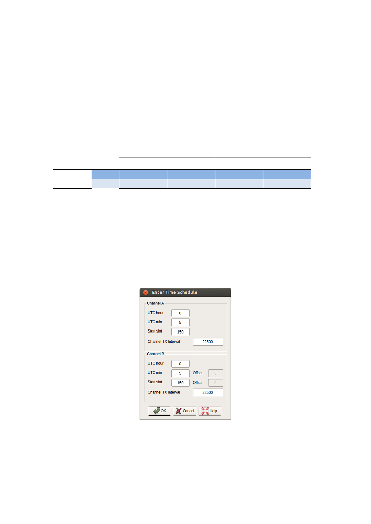
UTC Field
This field allows configuration of the time schedule the AtoN messages keep.
RATDMA does not require UTC time or the start slots to be defined, since they are
automatically allocated. For FATDMA, the UTC hour, minute and start slot index must be
provided. The valid start slot range is 0 to 2249.
The Channel TX Interval can be provided in slot units (2250 slots per minute). It corresponds
to the reporting interval for modes B and C. For mode A, the Channel Transmission Interval is
double of the Reporting Interval, as depicted in the figure below.
Channel Transmission Interval 1
Channel Transmission Interval 2
Reporting Interval 1
Reporting Interval 2
Reporting Interval 3
Reporting Interval 4
Mode A
Ch 1
▌
▌
Ch 2
▌
▌
Information provided in these fields must be consistent to the configured transmission
mode. For this reason, some fields for each channel on modes A and B must match. This is
enforced automatically.
The following figure shows a typical FATDMA configuration for operation on mode A with a 5
minute reporting interval. Each channel is configured with a Channel TX Interval of 10
minutes. A UTC minute offset of 5 minutes is automatically added to allow the alternated
transmissions to be spaced 5 minutes apart.
Page 17
Copyright © 2015, Vesper Marine Ltd. All rights are reserved
Synthetic Field
This field provides an option to set the AtoN as a Synthetic or a Virtual Aid to Navigation. A
Synthetic Aid to Navigation indicates the position of a physical marker, i.e. channel markers,
lateral marker etc. A Virtual Aid to Navigation indicates the position of a location where no
physical marker exists such as a submerged rock or virtual shipping lanes.
TX Count and Seconds Field
These fields are for information purposes and
are not editable. The transmission count for
each AtoN is displayed for each channel. In
addition, the number of seconds that has
elapsed since the last transmission is
displayed.
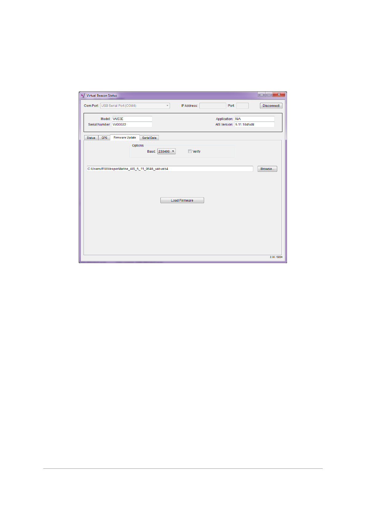
Virtual AIS Beacon Firmware Upgrades
To upgrade the VAB1252 firmware use Vesper Marine’s ‘Status & Firmware Update’ tool. The
connection process is the same as described above for the Beacon Configuration software.
Connect the device to a PC using the DB9 plug or Ethernet, and select the appropriate com
port (or IP address and com port for Ethernet enabled devices) and press connect. The
model, serial no., AIS version etc. fields will populate once the device has successfully
connected.
Page 18
Copyright © 2015, Vesper Marine Ltd. All rights are reserved
Once connected, click on the ‘Firmware Upgrade’ tab. From this tab you can browse for the
new version of Firmware you wish to upload to the device and load it.
Once the new firmware has been loaded your device will automatically reboot.

Page 19
Copyright © 2015, Vesper Marine Ltd. All rights are reserved
NMEA Command Interface
The Virtual AIS Beacon supports the NMEA-0183 (v4.10) command interface. All commands
start with a formatter such as $XXAID or !XXABM. The first two XX characters indicate the
talker ID and are ignored by the Virtual AIS Beacon, so can be set to the caller’s preference.
AtoN Configuration
The Virtual AIS Beacon supports the programming of its virtual AtoN marks using the
standard NMEA-0183 (v4.10) sentences. The corresponding legacy sentences as defined in
IEC 62320 Appendix A are also supported as indicated in Table 1.
Full sentence details can be obtained from the NMEA-0183 v4.10 standard. Note not all the
sentences will respond to a query as indicated by the queryable column.
Table 1 – Supported Public NMEA 0183 Sentences
Formatter
Description
Queryable
IEC
62320
AID
AtoN Identification Configuration
Yes
ACF
General AtoN Station Configuration
Yes
ACG
Extended General AtoN Station Configuration
Yes
ACE
CBR
Configure Broadcast Rates for AtoN Station
Messages
Yes
AAR
MEB1
Message Input for Broadcast
No
VER
Version details
Yes
BBM
Binary Broadcast Message
No
ABM
Addressed Binary Broadcast Message
No
Note 1: MEB is used to set the message contents. Five MEB payloads may be stored. The
corresponding CBR is used to determine the broadcast rates for the stored message.
After a command has been issued the Virtual AIS Beacon will respond with an OK or ERR
sentence to indicate a success or failure.
Examples: $PVSP,OK*2D
$PVSP,ERR,NOT FOUND*63
Example Configuration for a Virtual AtoN
A Beacon Cardinal N mark named VIRT ATON with an MMSI of 995121006 at position 36°
50.9866 S, 174° 45.1895 E on a mode A reporting interval of 3 minutes would be set on a
Virtual AIS Beacon with a serial number of GZ12345 using:
$ABAID,GZ12345,1,995121007,V,C*5B
$ABACG,995121006,00,,,,0,VIRT ATON,0000000000,C*05
$ABACF,995121006,7,3650.9866,S,17445.1895,E,1,,,,,,09,1,C*06
$ABCBR,995121006,21,0,0,0,1682,13500,1,0,3,1682,13500,C*0F

Page 20
Copyright © 2015, Vesper Marine Ltd. All rights are reserved
To configure the same AtoN with mode B timing at an interval of 3 minutes:
$ABCBR,995121006,21,0,0,0,1832,6750,1,0,0,1982,6750,C*07
To configure the same AtoN with mode C timing at an interval of 3 minutes:
$ABCBR,995121006,21,0,0,0,2132,6750,1,0,0,-1,0,C*27
Valid AtoN Types
The AtoN Type is defined in the ACF sentence and can be set to any one of the types shown
in Table 2. See ITU-R M.1371.4 Table 71 for additional details.
Table 2 – Valid AtoN Types
00
Type of AtoN not specified (default)
01
Reference point
02
RACON
03
Fixed structure (eg. oil platforms, wind farms)
04
Reserved for future use
05
Light, without sectors
06
Light, with sectors
07
Leading light front
08
Leading light rear
09
Beacon, Cardinal N
10
Beacon, Cardinal E
11
Beacon, Cardinal S
12
Beacon, Cardinal W
13
Beacon, Port hand
14
Beacon, Starboard hand
15
Beacon, Preferred channel port hand
16
Beacon, Preferred channel starboard hand
17
Beacon, Isolated danger
18
Beacon, Safe water
19
Beacon, Special mark
20
Cardinal mark N
21
Cardinal mark E
22
Cardinal mark S
23
Cardinal mark N
24
Port hand mark
25
Starboard hand mark
26
Preferred channel port hand
27
Preferred channel starboard hand
28
Isolated danger
29
Safe Water
30
Special mark
31
Light vessel / LANBY/ Rigs

Page 21
Copyright © 2015, Vesper Marine Ltd. All rights are reserved
Note the AtoN must be added to the Virtual AIS Beacon using AID before any of the other
configuration sentences can be used. The AtoN must have a valid and unique MMSI and
must be set as a virtual AtoN.
To delete the AtoN use the AID sentence with the delete flag set:
$ABAID,GZ12345,0,995121007,V,C*5A
Example Binary Broadcast of an Area Special Message
To initiate an addressed or broadcast binary message a base MMSI must be loaded into the
Virtual AIS Beacon. This MMSI will support the transmission of BBM, ABM, and MEB
sentence encapsulated data. There can only be one base MMSI and it cannot be used to
transmit a position report.
A transmission will return an ABK to acknowledge the message has been sent and a VDO
with contents of the transmitted message.
For example to add a base MMSI 995121000 to send an ASM BBM (Message 8):
$ABAID,GZ12345,1,995121000,R,C*58
!ABBBM,2,1,0,0,8,05H0180iqwwv77t6JAC`e000000pwPHR:O7p0000077ugDAD<g000000pw,0*0C
!ABBBM,2,2,0,0,8,irR:OQH0000077v5pACt;000000,4*05
Decoded Area Special Message
DAC
1
FI
22
Msg Link ID
0
Notice Desc
9
Month, Day
0
Hour
24
Minute
60
Duration
262143
Scale factor
1
Precision
4
-122.4670
37.8073
-122.4688
37.8160
-122.4110
37.8265
-122.3940
37.8177
-122.3990
37.8045

Page 22
Copyright © 2015, Vesper Marine Ltd. All rights are reserved
Additional NMEA Output Sentences
In addition to the sentences in Table 1 the following standard NMEA 0183 outputs are
supported by the Virtual AIS Beacon. These may be output automatically or in response to a
query or command.
Table 3 – Additional NMEA Output Sentences
Formatter
Description
GGA
Global Positioning System Fix Data
RMC
Recommended Minimum Specific GNSS Data
GLL
Geographic Position – Latitude/Longitude
GSA
GNSS DOP and Active Satellites
GSV
GNSS Satellites In View
VTG
Course Over Ground & Ground Speed
TXT
Text Transmission
VDO
AIS VHF Data-Link Own Report
VDM
AIS VHF Data-link Message
ABK
AIS Addressed and Binary Broadcast Acknowledgement
MEB
Message Input for a Broadcast Command
Full sentence details can be obtained from the NMEA-0183 v4.10 standard.
Extended AtoN Configuration
In addition to the standard configuration sentences the Virtual AIS Beacon also supports an
extended set of commands that start with $PVSP formatter. The supported sentences are
summarized in Table 4.
Table 4 – Sentences Used For Extended Configuration
Formatter
Description
Queryable
SAT
Enable/Disable GPS Satellite Output
No
ATON,CLR
Clear all AtoN Configurations
No
ATON,PERSIST
Enable/Disable Persistence of a Mark Change
Yes
MEB,DEL
Delete a Stored MEB
No
NWK
Enable/Disable Ethernet on Coms Port
No
SAT – Enable GSA/GSV Output
Enable or disable (default) the output of GSA & GSV sentences to reduce the serial data
stream.
Returns: $PVSP,OK*2D
Example: $PVSP,SAT,1*72
Format: $PVSP,SAT,x
x 0=disable GSA/GSV output, 1=enable

Page 23
Copyright © 2015, Vesper Marine Ltd. All rights are reserved
ATON,CLR – Clear all AtoN Configurations
Delete all AtoN’s. No further transmissions will occur until new AtoN’s are created.
Returns: $PVSP,OK*2D
Example: $PVSP,ATON,CLR*4C
ATON,PERSIST – Enable Persistence of a Mark Change
Enable (default) or disable the persistence of changes that are made to marks through an
ACF. Disabling will prevent the changes from being written to the EEPROM memory. This is
useful to avoid wear on the EEPROM memory in cases where changes to the position of a
mark are frequent and changes are not required to be preserved over a power cycle.
Returns: $PVSP,OK*2D
Example: $PVSP,ATON,PERSIST,1*56
Format: $PVSP,ATON,PERSIST,x
x 0=disable EEPROM writes, 1=enable
MEB,DEL – Delete an MEB Message
Delete a stored MEB payload. To delete all stored MEBs omit an optional parameter.
Returns: $PVSP,OK*2D
Example: $PVSP,MEB,DEL,990000123,14,4*2F (Delete msg 14 index 4)
Example: $PVSP,MEB,DEL,990000123*1E (Delete all 990000123 msgs)
Example: $PVSP,MEB,DEL*02 (Delete all)
Format: $PVSP,SAT,xxxxxxxxx,x,x
xxxxxxxxx MMSI (optional)
x Msg ID (optional)
x Msg Index (optional)
NWK – Enable Ethernet on Coms Port
Enable (default with Ethernet option) or disable Ethernet on the Coms port. This command
cannot be sent when using the Ethernet connection, but can always be sent over a serial
RS232 connection on either the Coms or the GPIO port.
Returns: $PVSP,OK*2D
Example: $PVSP,NWK,1*66
Format: $PVSP,NWK,x
x 0=disable Ethernet (use RS232), 1=enable Ethernet

Page 24
Copyright © 2015, Vesper Marine Ltd. All rights are reserved
Extended NMEA Outputs
In addition to the sentences in Table 4 the following extended NMEA 0183 outputs are
supported by the Virtual AIS Beacon. These all begin with the $PVSP formatter and may be
output automatically or in response to a query or command.
Table 5 – Extended NMEA Output Sentences
Formatter
Description
Queryable
ATON,CNT
AtoN Count
No
ATON,ADDR
Binary Message Address
No
ATON,STATS
Transmission Statistics
Yes
SYNC
UTC Synchronization Details
Yes
ATON,CNT – AtoN Count
Reports the active and maximum number of AtoN’s currently configured.
Example: $PVSP,ATON,CNT,6,10*7F
Format: $PVSP,ATON,CNT,x,x
x Count of currently configured AtoN’s
x Maximum number of licensed AtoN’s
ATON,ADDR – Binary Message Address
Reports the the address that will be used by the Virtual AIS Beacon when a base MMSI is
configured for broadcasting an addressed binary message.
Example: $PVSP,ATON,ADDR,0*1E
Format: $PVSP,ATON,ADDR,xxxxxxxxx
xxxxxxxxx MMSI to use as the address

Page 25
Copyright © 2015, Vesper Marine Ltd. All rights are reserved
ATON,STATS – Transmission Statistics
Returns the total transmission count for a given AtoN and the slot count at the last
successful transmission.
Example: $PVSP,ATON,STATS,512996001,0,0,0,0*4D
Format: $PVSP,ATON,STATS,xxxxxxxxx,x,x,x,x
xxxxxxxxx MMSI
x Channel 1 TX count
x Channel 1 last TX slot
x Channel 2 TX count
x Channel 2 last TX slot
Note: This information together with the SYNC output can be used to determine the exact
UTC time of the last transmission on each channel.
This sentence may be queried with $--ANQ,ATON,STATS for all MMSI’s or $--
ANQ,ATON,STATS,xxxxxxxxx for a single MMSI.
SYNC – UTC Synchronisation Details
Reports the slot frame to UTC synchronization details for the Virtual AIS Beacon.
Example: $PVSP,SYNC,0,0,NONE*08
Format: $PVSP,SYNC,x,x,x
x UTC Hour of frame sync
x UTC Minute of frame sync
x The slot count at the frame sync. NONE is reported if it is
not currently synchronized.
AtoN Queries
A query is initiated using the formatter $XXANQ followed by the sentence to be queried.
Note XX is ignored by the Virtual AIS Beacon so can be set to the callers preference.
For example to query all the configured marks MMSI details:
$VMANQ,AID*25
For a complete summary of the AtoN details query ATON:
$VMANQ,ATON*7D
This returns the following sentences: ATON,CNT ATON,ADDR SYNC followed by the following
for each AtoN: AID ACF ACG CBR ATON,STATS

Page 26
Copyright © 2015, Vesper Marine Ltd. All rights are reserved
Technical Information
System Specifications
Access mode
RATDMA or FATDMA
Transmission mode
Type 3 AtoN operates in mode A, B or C
Radio frequency
156.025 to 162.025 MHz
AtoN marks
Maximum of 65 (dependent on purchased configuration)
Message formats
ITU-R M.1371 - Message 6, 8, 12, 14, 21
Number of transmitters
1 x AIS
Number of receivers
2 AIS / 1 GPS (50 channel with SBAS)
AIS receive Sensitivity
-113dBm
GPS receiver sensitivity
-142 dBm acquisition. -159 dBm tracking
Power supply
10-16 VDC. AC/DC isolated power pack 12V, 5A
Transmission power output
41 dbm (12.5W)
GPS antenna connector
TNC connector
VHF antenna connector
S0239 connector. 50 ohm, max 2:1 VSWR
Power connector
2 pin circular
Coms connector
10 pin circular
GPIO connector
16 pin circular
Serial data
2 x RS232
Operating temperature
-25°C to +55°C (-13°F to 131°F)
Water tightness
IP67
Size
162mm by 122mm by 90mm high - excluding mounting lugs
(6.32” x 4.8” x 3.54” high)
Power consumption
Standard model: 3W nominal, 52W peak (12VDC)
Ethernet model: 4W nominal, 52W peak (12VDC)
GPS antenna
Construction: IPx7 sealed enclosure with 10m (32.8 ft) RG58U cable and
preinstalled TNC connector. Includes pole (standard 1”x14 marine) and
base mount.
Dimensions: 90mm (3 1/2") diameter x 118mm (4 2/3") height when used
with base mount
Compliance
* ITU-R M.1371, Technical characteristics for an automatic identification system
using time-division multiple access in the VHF maritime mobile band
* IEC 62320-5, Automatic Identification Systems (AIS) – Part 2, AIS AtoN Stations –
Operational and performance requirements, method of testing and required test
results
* IEC 61108 - "Maritime navigation and radio communication equipment and
systems - Global positioning system performance standards"
* IEC 61162 - "Maritime navigation and radio communication equipment and
systems - Digital interfaces"
*EN 60945 - "Maritime navigation and radio communication equipment and
systems - Durability and resistance to environmental conditions“
* IALA Recommendation O – 143: On Virtual Aids to Navigation
* IALA Recommendation A-126: On The Use of the Automatic Identification System
(AIS) in Marine Aids to Navigation Services
* NMEA 0183, Standard For Interfacing Marine Electronic Devices
Vesper Marine is committed to continuously improving our products. As a result, specifications may change and there may
also be differences between the product and this manual.

Page 27
Copyright © 2015, Vesper Marine Ltd. All rights are reserved
Technical Accuracy
The information contained in this document is to the best of our knowledge correct at the
time of publication. However, we reserve the right to change specifications, installation and
operating instructions without notice as part of our ongoing product development and
improvement programs.
No liability can be accepted for any inaccuracies or omissions in this document, or any other
document provided by Vesper Marine Ltd, although every effort has been made to ensure it
is as complete and accurate as possible.
General Warnings
The Virtual AIS Beacon works in cooperation with other vessels and systems such as AIS
transceivers, VHF and GPS. The accuracy of this device and the AIS system can be affected by
many factors, including equipment failure or defects, environmental conditions and incorrect
installation. Vesper Marine does not warrant that this product is error-free. It is the user’s
responsibility to exercise common prudence and care when configuring and using the Virtual
AIS Beacon.
Vesper Marine Limited cannot be held liable for any injury, damage or loss caused by,
during, or because of the installation, use or inability to use this Virtual AIS Beacon. The
Virtual AIS Beacon is to be installed and used entirely at your own risk. By installing and/or
using the Virtual AIS Beacon you fully accept this risk and agree to hold Vesper Marine
Limited harmless.

Page 28
Copyright © 2015, Vesper Marine Ltd. All rights are reserved
Obtaining Warranty Service
To obtain warranty service, please contact us. If you are unable to contact Vesper Marine
directly, then contact the dealer where you purchased the unit. You must have the original
sales receipt.
Vesper Marine Ltd.
45 Sale Street, Freemans Bay
PO Box 91164, Victoria Street West
Auckland 1142
New Zealand
Phone: +64 (0)9 950 4848
Fax: +64 (0)9 950 4085
www.vespermarine.com
support@vespermarine.com
You must contact Vesper Marine and obtain a return authorization before returning
equipment for repair.

Page 29
Copyright © 2015, Vesper Marine Ltd. All rights are reserved
Declaration of Conformity
This device complies with part 15 of the FCC Rules. Operation is subject to the following two
conditions: (1) This device may not cause harmful interference, and (2) this device must
accept any interference received, including interference that may cause undesired
operation.
Vesper Marine declares that this product is in compliance with the essential requirements
and other provisions of the R&TTE directive 1999/5/EC.
For details and a copy of the Declaration of Conformity see
www.vespermarine.com/compliance.
This product is for use worldwide, including the following countries:
AT
BE
BG
CH
CY
CZ
DE
DK
EE
ES
FI
FR
GR
HU
IE
IS
IT
LT
LU
LV
MT
NO
NL
PL
PT
RO
SE
SI
SK
UK
Electronic Waste Recycling
Various regional and national regulations exist regarding the recycling of certain
electronics. Please consult your local authorities or contact Vesper Marine for
recycling information.
Copyright Notice
Copyright © 2015, Vesper Marine Ltd. All rights are reserved.
Unless otherwise indicated, all documentation and operating software contained within this
product or distributed with this product is copyrighted by Vesper Marine Ltd. All rights are
reserved.
Except for short quotations in a review, no portions of this document or the software
contained within this product may be reproduced or transmitted in any form or by any
means without prior written permission of Vesper Marine Ltd.
Portions of this product may use software licensed under the GNU GPL or a modified GPL.
Source code for the applicable software is available upon request from Vesper Marine Ltd.
VAB1252-150922