Vesper Marine VESPWMX850 AIS WatchMate - WMX850 User Manual
Vesper Marine Limited AIS WatchMate - WMX850
User Manual

AISWatchMate®
Class B AIS Transceiver
Model: WMX850
WMX850-504-1110
Trademarks
AISWatchMate is a registered trademark of Vesper Marine Ltd. All
other product names are trademarks or registered trademarks of their
respective owners.
Copyright Notice
Copyright © 2010, Vesper Marine Ltd. All rights are reserved.
Unless otherwise indicated, all documentation and operating
software contained within this product or distributed with this
product is copyrighted by Vesper Marine Ltd. All rights are reserved.
Except for short quotations in a review, no portions of this document
or the software contained within this product may be reproduced or
transmitted in any form or by any means without prior written
permission of Vesper Marine Ltd.
Portions of this product may use software licensed under the GNU
GPL or a modified GPL. Source code for the applicable software is
available upon request from Vesper Marine Ltd.
Technical Accuracy
The information contained in this document is to the best of our
knowledge correct at the time of publication. However, we reserve
the right to change specifications, installation and operating
instructions without notice as part of our ongoing product
development and improvement programs.
No liability can be accepted for any inaccuracies or omissions in this
document, or any other document provided by Vesper Marine Ltd,
although every effort has been made to ensure it is as complete and
accurate as possible.
- 2 -
General Warnings
The AISWatchMate works in cooperation with other vessels and
systems such as transceivers and GPS. The accuracy of this device
and the AIS system can be affected by many factors, including
equipment failure or defects, environmental conditions and incorrect
installation, handling or use. Vesper Marine does not warrant that
this product is error-free. It is the user’s responsibility to exercise
common prudence and navigational judgment. This device should
not be relied upon as a substitute for such prudence and judgment.
Always maintain a permanent watch so that you can respond to
situations as they develop.
The prudent mariner will not rely on a single aid to navigation. The
user should verify the information obtained from the AISWatchMate
is in accordance with expected situations and conditions. The
information is not guaranteed to be accurate or reliable and the
AISWatchMate is not a substitute for proper seamanship.
Vesper Marine Limited cannot be held liable for any injury,
damage or loss caused by, during, or because of the installation,
use or inability to use this device. The AISWatchMate is to be
installed and used entirely at your own risk. By installing and/or
using the AISWatchMate you fully accept this risk and agree to
hold Vesper Marine Limited harmless.
RF Emissions Warning
CAUTION: This device generates and radiates electromagnetic
energy. This device must be installed and operated according to the
instructions contained in this manual. Failure to do so may result in
product malfunction and / or exposure to potentially harmful levels
of radio frequency radiation.
CAUTION: Never operate this device unless it is connected to a
- 3 -
VHF antenna.
The system has a Maximum Permissible Exposure (MPE) radius of
1m from the antenna. This has been determined assuming the
maximum power of the transmitter and using a standard half-wave
monopole VHF antenna with a maximum gain of 3dBi and
termination impedence of 50 ohms.
When installing the antenna and operating the equipment consider
the following:
●The antenna should be mounted as high above deck as
possible.
●Higher gain VHF antennas will require a larger MPE radius.
●Do not operate the unit when anyone is within the MPE
radius of the antenna.
●The antenna should not be collocated or operated in
conjunction with any other transmitting antenna.
MMSI Programming Warning
IMPORTANT: In most countries the operation of an AIS unit is
included under the vessel's marine VHF license provisions and the
vessel on which this device is to be installed may be required to
possess a current VHF radiotelephone license which lists the AIS
system and the vessel Call Sign and MMSI number.
An MMSI number is required in order for this device to operate
as a transmitter.
Please contact the relevant authority in your country for more
information.
- 4 -
For Customers in the USA
This device must be programmed with data corresponding to the
vessel on which it will be installed. Programming must be carried out
by a Vesper Marine dealer. The included instructions contain
information on how to verify the correct programming.
WARNING: It is a violation of the rules of the Federal
Communications Commission to input an MMSI that has not been
properly assigned to the end user, or to otherwise input any
inaccurate data in this device
GPS Antenna
The AISWatchMate Transceiver has a built-in GPS patch antenna.
This antenna requires a clear view of the sky. The performance of the
internal GPS antenna is also highly dependent on the environment in
which the device is mounted. The antenna performance maybe
significantly reduced if the AISWatchMate is installed on, under, or
near large metal structures. If you are mounting the display in a
location which will not provide adequate GPS signal coverage then
you must install a dedicated external GPS antenna. You cannot share
a GPS or GPS antenna. See the GPS Installation section for more
information on installing an external GPS antenna.
Compass Safe Distance
Mount your AISWatchMate Transceiver at least 0.6m (2 feet) from
any compass. Test your compass to verify that it operates properly
when this device is operating.
- 5 -

Electronic Waste Recycling
Various regional and national regulations exist regarding the
recycling of certain electronics. Please consult your local
authorities or contact Vesper Marine for recycling
information.
Care Notice
To provide protection against the damaging effects of UV light, it is
recommended to replace the cover when not in use.
Take care when cleaning to avoid damage:
●Be careful when wiping the display screen to avoid
scratching. Use a clean soft damp cloth.
●Do not use acid, ammonia, solvents, or any abrasive products.
Standards
This product complies with the following standards under the
European R&TTE directive for Article 3.1(a), 3.1(b), 3.2 and 3.3(e):
–IEC 62287-1: 2006-3 Maritime navigation and radio-
communication equipment and systems – Class B shipborne
equipment of the automatic identification system (AIS) – Part
1 Carrier-sense time division multiple access (CSTDMA)
techniques.
–IEC 60945: 2002-08 Maritime navigation and radio-
communication equipment and systems – General
Requirements – Methods of testing and required test results.
–IEC 61108-1 Global navigation satellite systems (GNSS) –
Part 1 Global positioning system (GPS) Receiver equipment
– Performance standards, methods of testing and required
- 6 -
results
–EN 301 843-1 v1.2.1 (2004-06) Electromagnetic
compatibility and Radio spectrum matters (ERM);
Electromagnetic Compatibility (EMC) standard for marine
radio equipment and services; Part 1: Common technical
requirements.
–EN 50385: 2002 Product standard to demonstrate the
compliance of radio base stations and fixed terminal stations
for wireless telecommunication systems with the basic
restrictions or the reference levels related to human exposure
to radio frequency electromagnetic fields (110MHz – 40GHz)
– General Public
–EN 50383: 2002 Basic standard for the calculation and
measurement of electromagnetic field strength and SAR
related to human exposure from radio base stations and fixed
terminal stations for wireless telecommunication systems
(110 MHz - 40 GHz).
–EN 60950-1: 2001 Information technology equipment –
Safety – Part 1: General Requirements.
- 7 -

Declaration of Conformity
Vesper Marine declares that this product is in compliance with the
essential requirements and other provisions of the R&TTE directive
1995/5/EC.
This product is for use worldwide, including the following European
countries:
AT BE BG CH CY CZ DE DK
EE ES FI FR GR HU IE IS
IT LI LT LU LV MT NO NL
PL PT RO SE SI SK UK
This device is also approved for use in the United States, Canada,
Australia and New Zealand.
- 8 -
Table of Contents
Trademarks.....................................................................................2
Copyright Notice............................................................................2
Technical Accuracy........................................................................2
General Warnings...........................................................................3
RF Emissions Warning..............................................................3
MMSI Programming Warning...................................................4
For Customers in the USA....................................................5
GPS Antenna..............................................................................5
Compass Safe Distance..............................................................5
Electronic Waste Recycling.......................................................6
Care Notice................................................................................6
Standards.........................................................................................6
Declaration of Conformity..............................................................8
Glossary........................................................................................15
Introduction...................................................................................17
Range.......................................................................................18
Bearing.....................................................................................19
Closest point of approach (CPA).............................................19
Time until CPA (TCPA)..........................................................19
Important Information..................................................................20
Specifications................................................................................21
Installation....................................................................................25
Requirements...........................................................................25
Mounting the Display..............................................................26
VHF Antenna Installation........................................................26
GPS Antenna Installation.........................................................27
Connectors...............................................................................28
Power/Data Cable Wiring........................................................29
Minimum Connections.............................................................30
Connecting an Optional Heading Sensor or Chart Plotter.......31
- 9 -
Connecting an Optional External Alarm..................................31
Using a Relay to Control a High Current External Device......32
GPS Backup Power..................................................................33
Using the USB Connection......................................................33
Using your AIS WatchMate when powered by USB..............34
Configuration...........................................................................34
Important Notice.................................................................37
Power Button................................................................................38
One Minute Startup Time........................................................38
Initial Profile Setting................................................................38
Buttons..........................................................................................38
Display Screens............................................................................39
Home Page – Situation Display...............................................39
Range Rings........................................................................40
Plotting Range.....................................................................40
Target count.........................................................................40
Selecting a Target................................................................40
Icon Meanings.....................................................................41
Main Menu...............................................................................43
Target List...........................................................................43
Plotting Range.....................................................................43
Profile..................................................................................43
Clear Selection....................................................................43
Weather Reports..................................................................43
Fleet List..............................................................................44
Message List........................................................................44
GPS Position.......................................................................44
GPS Status...........................................................................44
AIS Status............................................................................44
Send MAYDAY..................................................................44
Anchor Watch.....................................................................45
Setup....................................................................................45
- 10 -
Target List................................................................................46
Target Display..........................................................................48
CPA Graphical Display............................................................51
Safety Message List.................................................................53
Safety Message Display...........................................................55
Fleet List .................................................................................57
Weather Reports ......................................................................57
GPS Position Display...............................................................57
GPS Status Display..................................................................57
AIS Status Display...................................................................58
MMSI Configured...............................................................59
Silent Mode is Off...............................................................59
Startup Complete.................................................................59
GPS Position Fix.................................................................59
Position Report Sent............................................................60
Frequency............................................................................60
Mode....................................................................................60
RSSI....................................................................................60
Rx Msg Count.....................................................................60
Tx Msg Count......................................................................60
CS Thres..............................................................................60
Using the Anchor Watch..........................................................61
Use of Heading Data...........................................................63
Effect of GPS Antenna Reference Location.......................63
Auto Clear...........................................................................64
Icon Meanings Within Anchor Watch................................64
Displaying Information About your AIS WatchMate.............65
Target Filters.................................................................................66
Range Filter..............................................................................66
Speed Filter..............................................................................66
CPA Filter................................................................................67
TCPA Filter..............................................................................67
- 11 -
Target Alarms...............................................................................68
Guard Alarm............................................................................69
CPA Alarm...............................................................................70
CPA.....................................................................................70
Time (TCPA).......................................................................70
Target Speed........................................................................71
Your Speed..........................................................................71
Profiles..........................................................................................72
Harbor......................................................................................72
Coastal......................................................................................72
Offshore...................................................................................72
Anchor......................................................................................72
Setup Mode...................................................................................73
Target List Settings..................................................................73
Data display in target list.....................................................73
Sort targets by priority.........................................................74
Inactive target display time.................................................74
Alarm Settings.........................................................................74
Lost position alert................................................................74
Safety message handling.....................................................75
NMEA device alerts............................................................75
Alarm mode.........................................................................75
Test the alarm......................................................................76
Navigation Settings..................................................................76
Course and heading mode...................................................76
Bearing to target mode........................................................76
Default display orientation..................................................77
GPS Smoothing...................................................................77
GPS SBAS (WAAS, EGNOS)............................................77
Simulation mode.................................................................77
Display Settings.......................................................................78
Brightness............................................................................78
- 12 -
Contrast...............................................................................78
Turn display off when idle..................................................78
About your AIS WatchMate...............................................78
Preference Settings...................................................................79
Language.............................................................................79
Date format..........................................................................79
Metric or imperial................................................................79
AIS Transceiver.......................................................................79
Silent Mode.........................................................................79
Your vessel AIS details.......................................................79
I/O Port Settings.......................................................................79
NMEA input........................................................................79
NMEA output......................................................................79
Additional Settings...................................................................79
Reset all settings..................................................................79
Settings Associated with Each Profile.....................................80
Display orientation..............................................................80
Target speed filter................................................................81
Target range filter................................................................81
Target CPA filter.................................................................82
Target TCPA filter..............................................................83
Guard alarm range...............................................................83
CPA alarm...........................................................................84
CPA alarm - Time...............................................................84
CPA alarm - Target Speed..................................................85
CPA alarm - Your speed.....................................................86
Built-in Integrity Test (BIIT)........................................................87
Device Alerts................................................................................88
Troubleshooting............................................................................89
Display shuts off......................................................................89
Won't shut off when I press the power button.........................89
CPA alarm doesn't sound.........................................................89
- 13 -
Alarms sounds for every target................................................89
Warranty – North America...........................................................90
Warranty - Australia and New Zealand........................................91
Warranty - European Union..........................................................92
Obtaining Warranty Service.........................................................93
- 14 -

Glossary
AIS Universal Shipborne Automatic Identification
System. A system of transceivers installed on vessels
which send continuously updated navigation
information. An AIS receiver or transceiver is used to
monitor these transmissions and the AISWatchMate is
used to display this information and trigger alarms
when there is a risk of collision.
BRG /
Bearing
The location of another vessel typically expressed as
true or magnetic degrees. May also be expressed as
relative degrees from your vessel's heading.
Class A/B There are two classes of AIS transceivers. Class A are
used on vessels which have mandatory requirements
to carry AIS transceivers. Class B are used on vessels
for which AIS transceivers are optional.
COG Course over ground. The course a vessel is making
which is not necessarily the same as the vessel's
heading.
CPA Closest point of approach. The nearest distance in
nautical miles two vessels will come to one another if
they both maintain their current course and speed.
Filter A set of criteria used to determine if a target should
be included in the target list, such as its range or
speed.
GPS Global Positioning System. Used to provide your
vessel's current position, course, and speed.
IMO International Maritime Organization. A unique IMO
number is permanently assigned to each ship and may
- 15 -

be used to find additional registration information for
a particular vessel.
HDG /
Heading
The course a vessel is steering.
MMSI Maritime Mobile Service Identity. Used as a radio
identifier for each vessel with digital radios such as an
AIS transceiver. Vessels may also transmit their name
to facilitate easier identification. These transmissions
occur at a different interval than position information
and as a result the name may not be immediately
available. All AIS transceivers require a unique
MMSI. The AISWatchMate will not transmit until you
configure your MMSI.
Profile A group of settings. Profiles allow you to organize
filter and alarm settings and activate them together
when your navigation situation changes.
RNG /
Range
The distance in nautical miles between two vessels.
ROT Rate of turn. The number of degrees a vessel is
turning over a specified amount of time. Usually per
minute but may also be per 30 seconds.
SOG Speed over ground. The actual speed in knots a vessel
is making over the ground.
Target Another vessel for which AIS information has been
received.
Target List The set of all targets which meet the filter
requirements.
TCPA The time until the closest point of approach.
- 16 -
Introduction
The AISWatchMate is a device which provides information to assist
in avoiding collisions at sea. It works by receiving and transmitting
data as part of the Universal Shipborne Automated Identification
Systems (AIS). The AIS system uses two dedicated VHF channels
designated for this purpose and with the installation of the
AISWatchMate to receive signals from other AIS-equipped vessels
you can view this information. In addition, your vessel data is
transmitted to other AIS-equipped vessels within range.
The AIS system provides several types of messages from other
vessels and base stations. Each type of message is sent at a different
interval based on the navigation status of the vessel. Vessels moving
or turning faster send out navigation information more frequently
than vessels at anchor. Data received from other vessels is split
between two types: navigation information and voyage information.
Vessel navigation and position information is generated by an on-
board GPS or similar navigation device and is sent frequently.
Voyage information contains the ship's name, its destination, size,
type, cargo, etc. This data is typically only sent once every few
minutes.
The AISWatchMate provides a means to view how recently
information has been received from each vessel and this data is
designed to help you determine how accurate and dependable the
information may be at any given time.
The AISWatchMate refers to each vessel other than your own as a
target. Associated with each target are the most recently received
position, navigation, and voyage information. Also associated with
each target are computed data to help determine the risk of a
collision.
The targets are contained within a target list. The AISWatchMate
- 17 -

allows you to view the target list and also examine each target in
detail. By default, the target list is ordered by priority. You can
disable priority ordering if you wish. However, by viewing targets in
a prioritized fashion you can focus your interest on the targets most
likely to pose a collision risk first. Similarly, whenever a target
triggers an alarm you don't have to scroll to find it. The target is
displayed immediately with an indication of the cause of the alarm.
The AISWatchMate utilizes data from its built-in GPS receiver to
assist you in determining the risk of a collision with each target.
Multiple targets are automatically and continuously tracked
simultaneously. Alarms are associated with each individual target
and when an alarm is muted for one target it does not affect any other
targets which might also trigger alarms.
The computed data for each target includes the following items. Note
that in order to compute this data your vessel's current position,
course, and speed are required. The AISWatchMate receives this
information continuously from its built-in GPS.
If the built-in GPS does not have a valid “fix” then this
information will not be computed and displayed. In addition,
your own information will not be transmitted to other vessels.
Range The AISWatchMate computes the range
(distance in nautical miles) to each target
and displays it along with the target
information.
- 18 -

Bearing The bearing to each target is also
displayed. The bearing may be shown as
magnetic to facilitate quick visual
identification using a compass or
binoculars. However, if you wish you can
change a setting to display bearings in
degrees true or relative to your vessel's
current heading.
Closest point of
approach (CPA)
The CPA is the closest a target will come
to your vessel if both your vessel and the
target maintain their existing course and
speed. It is displayed in nautical miles to
the nearest tenth or hundredth. As either
your vessel or the target changes its course
or speed, the CPA (along with all other
computed data) is automatically
recomputed and redisplayed.
Time until CPA
(TCPA)
This is the amount of time until the CPA
will occur. It indicates how much time is
available before the two vessels will reach
their nearest distance to each other. It is
displayed in minutes and seconds or just
minutes if the time exceeds one hour.
The AISWatchMate automatically updates these computed values
whenever new information is received from a target and also
whenever your vessel's position, speed, or course changes. The
information displayed is always the most up-to-date available but
because the AIS and GPS systems do not guarantee the frequency of
updates from each vessel it can be inaccurate and can become further
inaccurate as time progresses without continuous updates from both
- 19 -
vessels.
Always check to see how long it has been since an update was
received from a vessel when relying on this information,
particularly in close situations. You do this by examining the “age”
of the target. See the target display section for more details.
The AIS system also includes messages broadcast from other vessels
and shore stations which may be used to send navigation warnings,
weather information, etc. The AISWatchMate displays this
information on the messages page and by default is configured to
sound an alert when a message is received.
We are always interested in your suggestions, comments, ideas, and
criticisms. We continuously strive to improve our products and
would greatly enjoy hearing from you.
Please contact us through our website www.vespermarine.com or
via e-mail to support@vespermarine.com.
Important Information
Before using the AISWatchMate, it is important that you read and
fully understand this owner's manual and installation instructions.
Although more vessels continue to install AIS transceivers it is
important to remember that not all vessels carry AIS transceivers.
The AISWatchMate can only display information received from
properly equipped and operated vessels. In addition, the
AISWatchMate relies on the accuracy of the GPS system. A failure or
compromised operation of either of these systems will reflect on the
accuracy of the data displayed and alarms triggered by the
AISWatchMate.
- 20 -

Specifications
Size (not including cables or
mounting bracket)
208mm wide x 135mm high x
76mm depth
(8 3/16” x 5 5/16” x 3”)
Flush mount thickness 17mm (11/16”)
Mounting template Included
Power supply 12-24 VDC 1A max, 3W nominal
Environmental Watertight (USCG CFR-46, IPx7)
Operating temperature -25°C to +55°C (-13°F to 131°F)
Storage temperature -25°C to +80°C (-13°F to 176°F)
LCD panel 125mm (5”) FSTN 320x240 backlit
LCD light level Off and multiple levels of
brightness
Serial data 1 USB port, 1 NMEA input
(RS422), 1 NMEA output (RS422)
Baud rates 4800 and 38400
NMEA output RMC, GSV, GSA, GGA, GLL,
VTG, VDO, VDM, TXT
NMEA input (optional) ALR, HDG, HDM, HDT
AIS messages displayed All Class A and Class B position
reports, voyage data, static data,
aids to navigation, search and
rescue, SART, meteorological /
hydrographic and broadcast safety
messages
(1,2,3,5,8,9,14,18,19,21,24A,24B)
- 21 -

Number of receivers 2 AIS, 1 DSC (timeshared)
Number of transmitters 1 AIS
Frequency range 156.025 – 162.025 MHz
Channel bandwidth 25 kHz
Sensitivity -107 dBm < 20% PER
Power output 33 dBm (2W)
GPS 50 channel
GPS sensitivity -159dBm tracking & navigation
-142dBm acquisition
GPS SBAS support WAAS, EGNOS, MSAS, GAGAN
Maximum number of
simultaneous targets displayed
150 (if more, then the lowest
priority target is replaced)
Maximum number of
simultaneous broadcast safety
messages displayed
30 (if more, then the oldest message
is replaced)
Maximum number of
simultaneous meteorological
stations displayed
30 (if more, then the oldest received
meteorological information is
replaced)
Maximum fleet size 50 vessels
External alarm Maximum current 150mA. Use an
external relay if more is required.
Power/data connector 10 pin circular. 2m cable included.
USB connector Mini USB. Optional waterproof
cable available.
- 22 -

GPS antenna connector TNC. Optional GPS antenna
available.
VHF antenna connector SO-239
VHF antenna required PL-259 connector. 50 ohm, max 2:1
VSWR
Vesper Marine is committed to continuously improving our products.
As a result, specifications may change and there may also be
differences between the product and this manual.
- 23 -
- 24 -
Installation
Requirements
The AISWatchMate requires a suitable VHF antenna which must be
supplied by the user and a clear view of the sky for the built-in GPS
or an external GPS antenna.
The following are required for installation:
●Various countries have regulations requiring a VHF radio
license to operate an AIS transceiver. Check with your local
authorities to determine the requirements for your area.
●You must have an assigned MMSI and Call Sign for your
vessel. If you do not have an assigned MMSI, contact the
relevant authority in your country. You must enter a valid
MMSI number into this device.
Once you enter the MMSI number it cannot be changed.
If you need to change the MMSI, please contact an
authorized dealer or Vesper Marine.
●A suitable VHF antenna or Vesper Marine AIS/VHF Antenna
Splitter. Performance cannot be assured if you use any other
antenna splitter. The use of an improper splitter may damage
your AISWatchMate and void your warranty.
●If you are not able to mount the unit with a clear view of the
sky or if your mounting location and / or other equipment
interferes with the built-in GPS antenna, then an optional
external GPS antenna is required. You must use a dedicated
GPS antenna which cannot be shared with any other
- 25 -
equipment. However, the GPS data produced by the
AISWatchMate is available for use by other optional
equipment connected to the NMEA output.
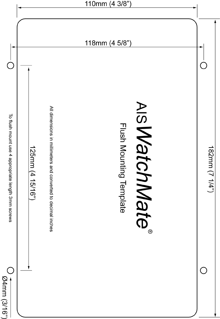
Mounting the Display
Your AISWatchMate is supplied with a trunnion mounting bracket if
you wish to mount it above or below a shelf or other support. You
may also mount the unit by cutting a hole in an instrument panel and
mounting it flush. Included is a template you can use to cut the hole
and drill four additional holes for the required fasteners. A gasket is
also included to seal the unit against your instrument panel.
Do not disassemble the unit or remove the screws which hold it
together. The unit is sealed and disassembly will void the warranty.
If you require service or assistance please contact your dealer or
Vesper Marine.
VHF Antenna Installation
The AISWatchMate must be connected to a suitable VHF antenna or
Vesper Marine AIS/VHF Antenna Splitter. Performance cannot be
assured if you use any other antenna splitter. The use of an improper
splitter may damage your AISWatchMate and void your warranty.
When installing the VHF antenna please take into consideration:
●The type of antenna should be an omnidirectional VHF
antenna designed for the marine band (156-162 MHz).
●There are AIS-frequency adapted antennas available. You
may also use a standard marine VHF antenna.
●The antenna must be dedicated and not connected to any
other equipment.
- 26 -
●Place your antenna as high as possible and at least 2-3 metres
(6-10 ft) above the water surface.
●Place your VHF antenna as far as possible from other
antennas and metal structures, especially other VHF, HF and
radar antennas. It is not recommended to place the VHF
antenna directly alongside a mast or another VHF antenna
such as on a mast-head.
GPS Antenna Installation
The AISWatchMate has an internal GPS patch antenna facing
upwards. This antenna requires a clear view of the sky. However, the
performance of the internal GPS antenna is also highly dependent on
where you place your AISWatchMate. For example, you may find that
it works well under a non-metallic dodger or spray hood but
performance may be reduced if the AISWatchMate is installed on,
under, or near metal structures. If you are mounting the display in a
location which will not provide adequate GPS signal coverage then
you must install a dedicated GPS antenna. You cannot share a GPS
or GPS antenna.
When installing an external GPS antenna please take into
consideration:
●Only use a 3.3VDC active antenna that contains a low noise
amplifier. Vesper Marine has available an optional external
GPS antenna designed specifically for use with the
AISWatchMate.
●The GPS antenna should be situated so it has an unobstructed
view of the sky above.
●Do not place the GPS antenna near or in the path of radar or
HF antennas.
- 27 -
●It is not necessary to change any settings when using the
optional Vesper Marine GPS antenna. Simply connect it to
the TNC connector on the back of the unit.
Considerations when using the internal GPS patch antenna:
●The AISWatchMate should be situated so it has no metal
obstructions over the top. The antenna is located in the back
“bulge” area at the top of the unit facing upwards.
●Avoid placing your hand or body over the antenna area as this
may reduce satellite signal strength.
Hint: Use the GPS Status screen to view satellite signal strengths
which will assist in determining the best location for the unit or
antenna.
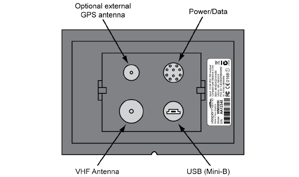
Connectors
- 28 -

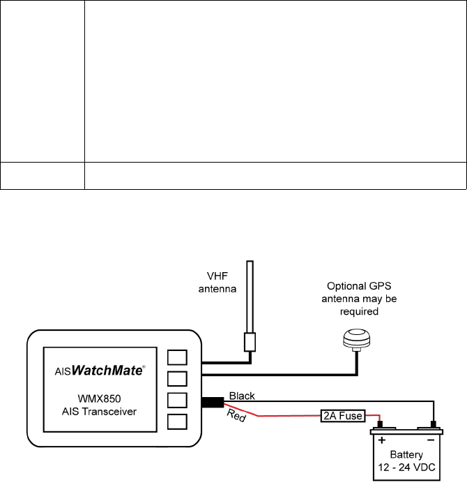
Power/Data Cable Wiring
A 2m (6.5') power/data cable with attached connector is supplied
with the AISWatchMate. You may extend this cable as necessary. It is
recommended that any splices made in the cable be done in a
weather tight area to prevent corrosion and failed connections.
Consult a marine electronics technician if you have any difficulties
or concerns about installation.
Insert the connector into the back of the display firmly and
completely, fully engaging the locking ring to ensure a watertight
seal.
Red DC positive (+) (12-24 volts). Ensure there is a circuit
breaker or fuse rated at 2A (max) in the positive power
connection. It is recommended to add a fuse if
necessary.
Black DC negative (-).
Gray NMEA data output positive. Connect this wire to the
NMEA data input (A or +) on another device such as a
chart plotter or radar.
Yellow NMEA data output negative. Connect this wire to the
NMEA data input (B or -) on another device such as a
chart plotter or radar.
Green NMEA data input positive. Connect this wire to the
NMEA data output (A or +) on another device, such as
a heading sensor.
White NMEA data input negative. Connect this wire to the
NMEA data output (B or -) on another device, such as
a heading sensor.
- 29 -
Blue External alarm. When the alarm is triggered and the
external alarm is enabled this wire will have the input
voltage (from the red wire) applied. You can use this to
provide power to an external buzzer, light or other
signal device.
Maximum current is 150mA. If your device requires
more current then an external relay must be used.
Others All other wires are not used. Leave them unconnected.
Minimum Connections
- 30 -
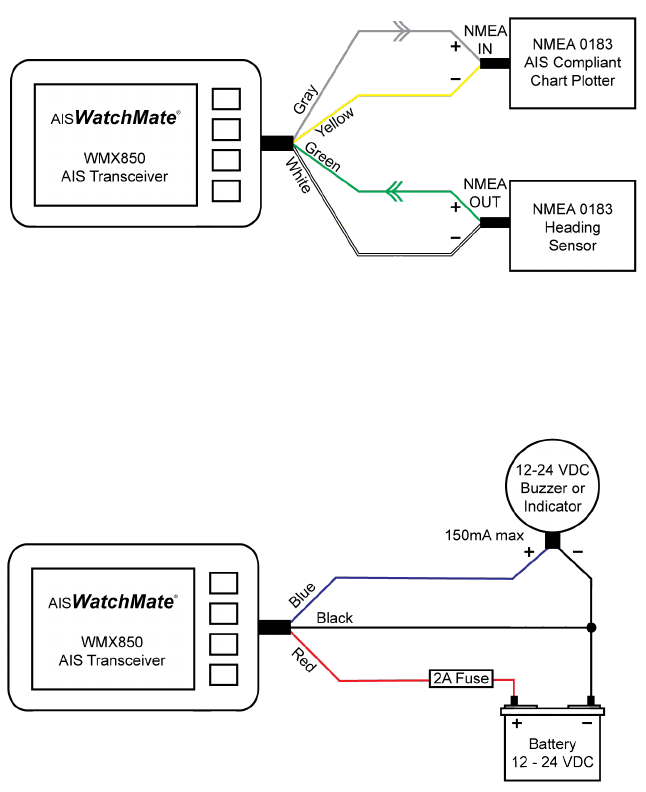
Connecting an Optional Heading Sensor or Chart Plotter
Connecting an Optional External Alarm
- 31 -
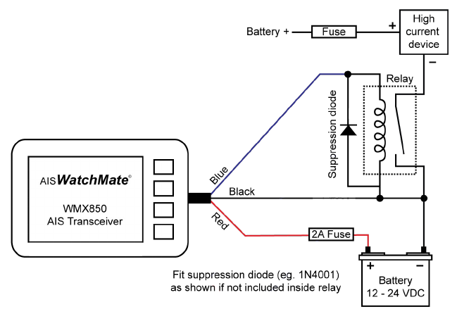
Using a Relay to Control a High Current External Device
When your external device requires more than 150mA you must use
an external relay. Ensure a spike suppression diode (eg. 1N4001) is
either provided by the relay or fitted externally.
You should also provide a fuse of the appropriate value to protect
against overload.
- 32 -
GPS Backup Power
To speed the time-to-first-fix, do not disconnect or switch off the
power supply to the AISWatchMate. If you do switch off the power
supply it may take longer for the built-in GPS to acquire satellite data
and a position fix. You can switch the unit off using the power button
on the front and it will continue to maintain the GPS almanac data as
long as the power supply to the AISWatchMate is maintained.
An extremely small amount of power is used to maintain the GPS
data so it should not have any significant effect on your battery.
However, if you wish to completely turn off the AISWatchMate, such
as when storing your vessel for an extended time, disconnect or
switch off the power supply.
Using the USB Connection
If you wish to connect your AISWatchMate to your PC for use with
charting or other software, use a USB cable with a Mini-B (male)
connector. One has been included with your AISWatchMate. These
are also widely available from computer stores.
Vesper Marine has available an optional waterproof USB cable
which is highly recommended if your AISWatchMate is installed in a
location where it is possible to get wet.
The AISWatchMate utilizes standard drivers that are supplied with
Windows, but in case the “Found New Hardware Wizard” cannot
locate the proper drivers, they are also included on the supplied CD.
The driver creates a “virtual COM port” which will be displayed the
first time the AISWatchMate is plugged into your computer.
You will need to configure your software to use this port (eg.
COM3) at 38,400 baud.
- 33 -
Using your AIS WatchMate when powered by USB
It is possible to use your AISWatchMate when powered only by the
USB connection to your computer. This is useful for configuring
your AISWatchMate at home prior to installation on your vessel. This
also allows you to use it as an AIS receiver and GPS without
connecting to an additional DC power source.
However, when operating under USB power there are several
limitations:
●No AIS data is transmitted
●AIS receiver sensitivity is reduced
●The maximum screen brightness is automatically decreased
●The external alarm is not triggered
A warning message is displayed whenever these limitations exist.
Important: Due to these limitations, this is not intended to be
the normal operating mode. It is only recommended to use USB
power to configure or learn about your AISWatchMate.
Configuration
Your vessel data, including MMSI number, must be entered into the
AISWatchMate. Your MMSI may have been entered already by your
dealer. Once entered, this information will be retained and it is not
necessary to enter it again.
Until this information has been entered, the AISWatchMate will
receive other vessel's AIS data but will not transmit yours.
To program your vessel data or check that it has been programmed
properly, select Setup from the main menu and select AIS
Transceiver. Choose the option for Your vessel AIS details.
- 34 -
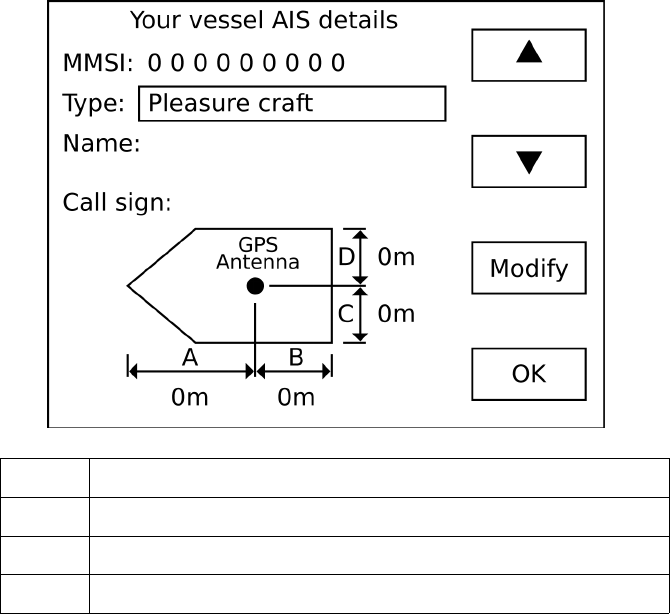
▲ Move the selection box to the previous field
▼ Move the selection box to the next field
Modify Enter a new value for the selected field
OK Save your changes and exit configuration
To enter or change data in a field, use the arrow buttons to position
the field selection box over the appropriate data and press the
Modify button. The field becomes active and the current character
position is indicated as shown below.
- 35 -
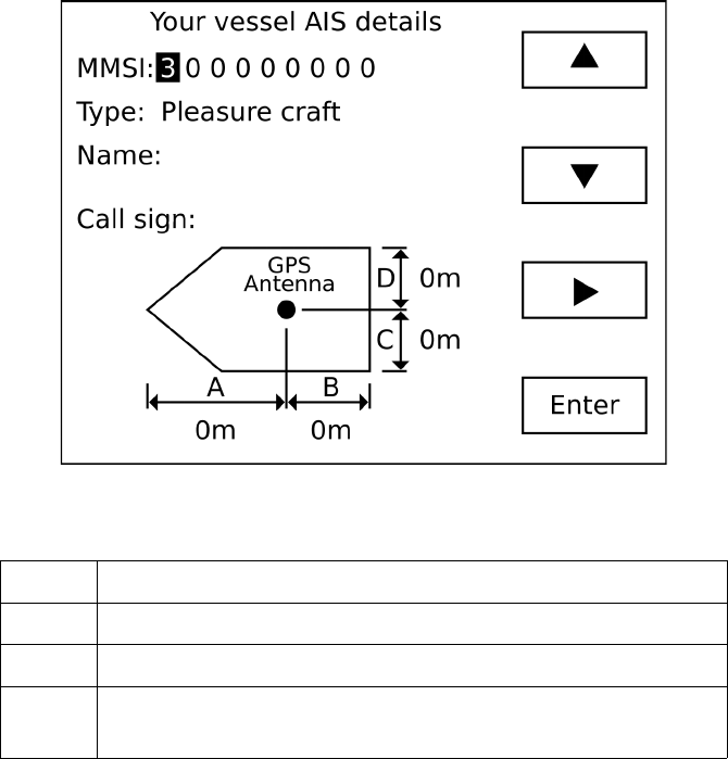
▲ Increase the value at the current character position
▼ Decrease the value at the current character position
Move to the next character position
Enter Complete the field entry and return to the previous screen
allowing you to select another field to modify
If you make a mistake and want to go back to the previous character
position, press the Enter button to accept the value and then press
the Modify button to change it again.
When you have finished entering your configuration data press the
OK button to save your changes.
- 36 -
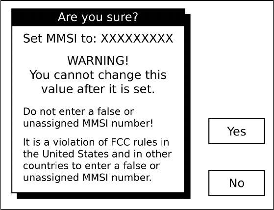
Important Notice
You cannot change the MMSI number once it has been saved in the
unit. Enter the number carefully and only use an assigned MMSI for
your vessel. If you need to change the MMSI number in your unit
you must contact an authorized dealer or Vesper Marine.
The AISWatchMate will not transmit your data until your MMSI
has been entered.
When you enter your MMSI number and press the OK button to save
it, the following screen is displayed. Press the Yes button to proceed
and save your changes. Press the No button to return to the
configuration screen.
If you wish to abort the configuration operation without saving any
changes, press and hold the power button for 2 seconds.
- 37 -
Power Button
Press the power button momentarily to turn on the AISWatchMate.
Press and hold the power button for 2 seconds to turn it off.
While the AISWatchMate is turned on, pressing the power button
momentarily allows you to change the display brightness.
One Minute Startup Time
The AISWatchMate will not begin to transmit for one minute after it
has been switched on. This startup time is required to determine
background noise levels on the AIS frequencies.
Initial Profile Setting
When you press the power button to turn on the AISWatchMate, you
will be prompted to select the current profile. This allows you to
switch profiles before any alarms are triggered.
No alarms will be triggered while the profile selection window is
displayed. You must select a profile and press the OK button.
Buttons
The AISWatchMate is designed to be simple and intuitive to operate.
In addition to the power button there are only four buttons. Next to
each button on the screen is a box indicating the button's function. If
no box appears next to a button then the button performs no function
at that time.
- 38 -
Display Screens
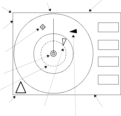
Home Page – Situation Display
The home page displays targets using a graphical situation display
similar to a radar.
The display is oriented either Heading-Up or North-Up depending on
the profile and settings. If heading data is not available for your
vessel, then it is oriented course-up or north-up. The heading or
course may be displayed in magnetic or true degrees depending on a
setting in setup mode.
You must have a valid GPS fix for any targets to be shown on the
situation display.
- 39 -
Select
Menu
Prev
Next
042T
[6nm]
Coastal
3 Targets
1 Filtered
1 Msg
Plotting range
Current
Alarm Profile
Nav Aid
Your
position
Your heading Total targets and
filtered targets
Safety messages
Ordinary target
Dangerous target
Guard range !
Transmit warning

Range Rings
The outer range ring corresponds to the current plotting range. The
inner range ring is ½ the plotting range.
If the guard alarm is enabled an additional dotted range ring is drawn
to indicate its position.
Plotting Range
The plotting range may be changed by using the Menu button.
Target count
The count of all targets includes targets which are not visible on the
plotting display because they are either out of range or have not sent
a position report yet. The count does not include targets which are
being filtered based on the current profile settings. If targets are
being filtered, the number of filtered targets is also shown.
Selecting a Target
Use the Next and Prev buttons to select targets. When you select a
target a small information window appears. Press the Select button to
see the full target details.
- 40 -
PACIFIC PEARL
RNG: 4.27nm SOG: 4.3K
CPA: 0.27nm TCPA: 13:49

Icon Meanings
An ordinary target. The triangle points in the direction of the
target's heading (or course if heading data is not available for the
target).
A dangerous target. This target meets one or more of your alarm
criteria.
An aid to navigation.
A dangerous aid to navigation. This target meets one or more of
your alarm criteria.
A search and rescue transponder (AIS SART).
This symbol appears around a target to indicate it is the currently
selected target. Press the Select button to view the complete target
details.
This symbol is overlayed over a target to indicate the target is
"lost". No AIS data has been received from the target within the
expected interval or 10 minutes for targets that haven't reported
their position. The expected interval is based on AIS-specified
transmission intervals and determined by AIS class and speed.
A circle appears around a target that is marked as a member of
your “fleet”.
Display is oriented North-Up for this profile. Use setup to change
the default orientation or the orientation associated with the
current profile. If this symbol is not displayed, then the display is
oriented Heading-Up.
- 41 -

Indicates your AIS data is not being transmitted. In order for your
AIS data to be transmitted you must have configured the MMSI
and the GPS must have a position fix. Other reasons are silent
mode has been enabled or a base station has commanded your
AIS transceiver to enter “quiet mode”. You can use the AIS Status
screen to determine the reason.
Important: The AISWatchMate will not begin to transmit for one
minute after it has been switched on. This startup time is required
to determine background noise levels on the AIS frequencies.
During this time, the warning symbol will be shown.
When used with a Vesper Marine AIS/VHF antenna splitter this
symbol indicates the VHF radio is in-use and AIS transmissions
are temporarily disabled.
From the situation screen you may use the following buttons:
Next Select the next target. Targets are selected in priority
order. The Next button starts with the highest priority
target. The list of visible targets may be scrolled with the
Next button and when no more targets are available, the
current selection is cleared.
Prev Select the previous target. The Prev button starts with the
lowest priority target. When no more targets are available,
the current selection is cleared.
Select Display the target details screen for the currently selected
target.
Menu Brings up a menu that allows you to change the current
plotting range, change your profile, enter setup, display a
list of all targets in priority order or view the list of
received weather or safety messages.
- 42 -
!
Note: Because the order of targets shown with the Next and Prev
buttons depends on their priority, pressing Next and Prev may not
always bring you back to the same target if their priorities have
changed. This occurs more frequently when targets or your own
vessel are making course changes.
Main Menu
The Menu button on the home screen situation display allows you to
select an option from the table below. Only the options which are
currently applicable are displayed on the menu, so not all options
will always be available.
Target List Displays the list of targets. See the Target List
section for more details. This option is only
available if targets exist.
Plotting Range Select the maximum range for the situation
display. The outer range ring corresponds to
this selection. The inner range ring represents
½ of the plotting range.
Profile Choose a profile of alarm and filter settings.
This allows you to quickly select from pre-
programmed groups of settings as your
situation changes. See the Profiles section for
more details.
Clear Selection Deselects the currently selected target and
removes the popup information window.
Weather Reports Displays the list of received meteorological and
hydrographic data. This option is only available
if this data has been received.
- 43 -
Fleet List Displays a list of members in your fleet. You
can remove members from this list. Members
are added to the list from the target details
menu when you are viewing a target. This
option is only available when one or more
targets has been added to the fleet list. You can
add a target to the fleet list using the Menu
button when the target you wish to add is being
displayed.
Message List Displays the list of received safety messages.
See the Safety Message section for more
details. This option is only available if one or
more safety messages has been received.
GPS Position Displays your current GPS position, course,
heading and speed. This option is only
available if a valid GPS position has been
received.
GPS Status Displays the GPS satellite receive status
showing satellites in view and active satellites.
AIS Status Displays the AIS operational status. You may
use this to determine the reason for transmit
warnings and number of messages
sent/received.
Send MAYDAY Sends a MAYDAY broadcast safety message to
all AIS-equipped vessels within range. You can
only send a broadcast safety message once per
minute. Before transmission, you will be
required to confirm your selection.
Important: Do not use this as your only means
- 44 -
of communicating a MAYDAY.
Anchor Watch Displays the Anchor Watch screen. Use this
screen to mark your anchor location and
observe your vessel in relation to your marked
location. You may also enable an alarm if your
vessel moves outside a preset circle around
your anchor location.
Setup Displays the settings you can change. Also
allows you to customize the alarm and filter
settings for the current profile. See the Setup
Mode section for more details.
Hint: To change the settings for each profile,
select the profile first and then use the Setup
menu.
- 45 -
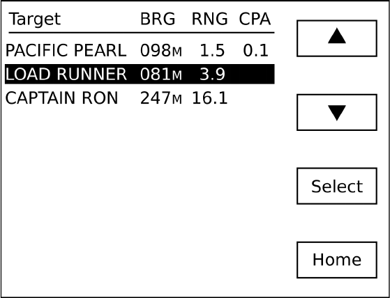
Target List
The target list contains all non-filtered targets. You can scroll
through the list to select a target to view in detail. By default, the
target list is continuously ordered by priority. The priority of a target
is based on its CPA, TCPA, range, and speed. Higher priority targets
are shown at the top of the list. In setup mode you can disable this
feature if you wish and targets will be displayed in the order they
were first received.
Each target shown in the target list indicates the CPA as well as the
bearing and range from your vessel to the target. This facilitates
visual identification. In setup mode you can change whether bearings
are shown as true, magnetic, or relative to your vessel's heading.
- 46 -

If the target and your vessel are not converging, such as when they
are moving apart, the target's CPA is blank.
If you wish, in setup mode you can configure the target list to display
each target's speed over ground (SOG) rather than CPA.
When this screen is displayed, you can use the following buttons:
▲ Scroll your selection up. This button is only active if it is
possible to scroll up.
▼ Scroll your selection down. This button is only active if it
is possible to scroll down.
Select Display detailed information about the selected target.
Home Return to the situation display.
- 47 -
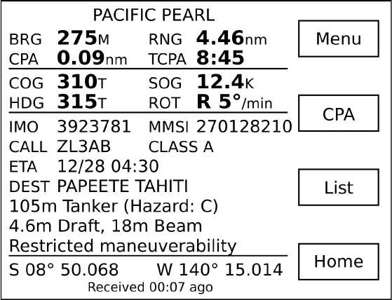
Target Display
The target display screen is shown when you select a target from the
target list or situation display. This screen contains detailed
information about the target. The information displayed will vary
depending on how much data has been received from the target and
the type of target.
AIS data for a target is received in several types of messages and
those messages may be received at different times. The interval at
which a target sends messages is based on the type of message, class
of target, its speed, rate of turn and other factors. As a result certain
information may not be available immediately from a target.
However, the AISWatchMate displays available information as soon
as it has been received. If you are viewing a target when new data
arrives for that target, the screen is refreshed with the new data.
Until voyage information has been received for a target, its name is
not available. In this case its MMSI number will be displayed instead
of the name and will look like <735023456>. Since voyage
information is received at a different interval than navigation
information it may take several minutes to appear.
A target may specify its navigation status and if available it is
displayed as “Motoring”, “Sailing”, “Anchored”, “Moored”, etc.
The navigation status may not be accurate.
An important piece of information indicates when data was last
received from a target. This is shown at the bottom of the target
details screen. Although bearing, range, CPA, and TCPA are
constantly updated by the AISWatchMate as your vessel moves, you
should consider the “age” of the information received from the target
in determining how accurate the displayed data may be and to assist
you in refining your assessment of collision risk.
- 48 -
If the target and your vessel will not converge, such as when they are
moving away from each other, the CPA is shown as None and
TCPA is not displayed.
When the TCPA is greater than one hour it is displayed in minutes
without the seconds (eg. 123min).
When the target display screen is shown due to an alarm condition
the reason for the alarm will be blinking (eg. RNG for a guard alarm
and CPA for a CPA alarm). The blinking stops when the alarm is
muted or the target is no longer in an alarm condition.
If a target has an age greater than 15 minutes, it is automatically
removed from the target list. You can change this number of minutes
within setup in the target list group.
- 49 -

While the target screen is displayed, you can use the following
buttons:
Menu Allows you to disable or re-enable alarms for this target.
Also allows you to add the target to your fleet. A target
which is a member of your fleet is shown with a circle
around its icon on the situation display.
Mute Disable alarms for this target. This function is only active
when an alarms is sounding for the target. See the section
on alarms.
CPA Display the relative position of the target at CPA. For
example, this helps you determine if a target will pass
ahead or behind you. See the CPA Display section. This
function is only active if a target is converging and
therefore has a CPA.
List Return to the target list screen.
Home Return to the situation display.
- 50 -
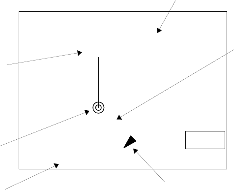
CPA Graphical Display
When a target is converging and has a CPA shown, the CPA button
is available on the target display. This button brings up a graphical
plot showing the relative position of the target at the time of CPA.
The display is oriented either Heading-Up or North-Up depending on
the current profile settings. If heading data is not available for your
vessel, then it is oriented course-up. The heading or course may be
displayed in magnetic or true degrees depending on a setting in setup
mode.
- 51 -
Back
042T
Your
position
Your heading
PACIFIC PEARL
Relative Position at C PA
CPA 0.28nm TCPA 7:56
0.3nm
Received 00:04 ago
When the last AIS
message was received
from this target
Relative position of the
target at the time of closest
point of approach
Distance
to target
at CPA
Time until closest point of approach (MM:SS)
Important notes:
1. No other targets are shown on this display. Only the current
target and your vessel are displayed.
2. The plotting distance shown on the screen between your
vessel and the target is always the same regardless of the
actual CPA. Always use the CPA value displayed to confirm
the expected distance at the time of closest point of approach.
- 52 -
Safety Message List
The message list displays safety messages received from other
vessels and shore stations. Safety messages are free-form text and
may pertain to emergencies, port operations, hazard warnings,
weather or other important information.
They may be broadcast to all AIS-equipped vessels within range or
may be specifically addressed to your vessel.
You can send a pre-programmed MAYDAY safety message to all
AIS-equipped vessels within range by selecting the Send MAYDAY
option from the main menu.
When a safety message is received, the message is displayed
immediately and an alert is sounded by beeping the alarm several
times. If you wish, you can disable the beep in setup mode.
The list of received safety messages is available from the main menu
of the situation display.
The message list shows the sender and as much of the message as
can fit on each line. To view the full message, select it from the
message list.
- 53 -
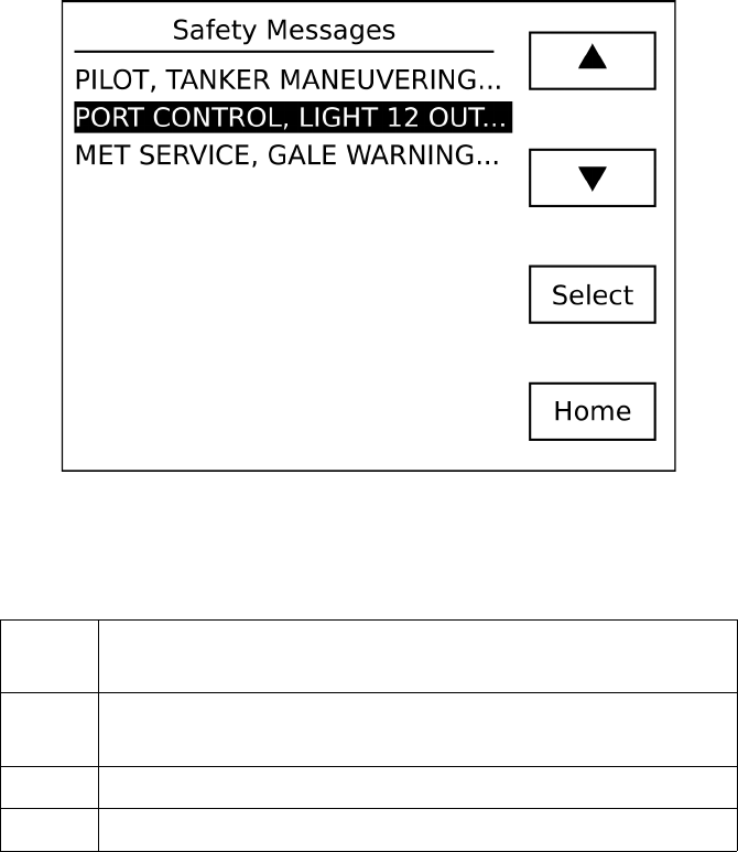
When the safety message list is displayed, you can use the following
buttons:
▲ Scroll your selection up. This button is only active if it is
possible to scroll up.
▼ Scroll your selection down. This button is only active if it
is possible to scroll down.
Select Display the safety message.
Home Return to the situation display.
- 54 -
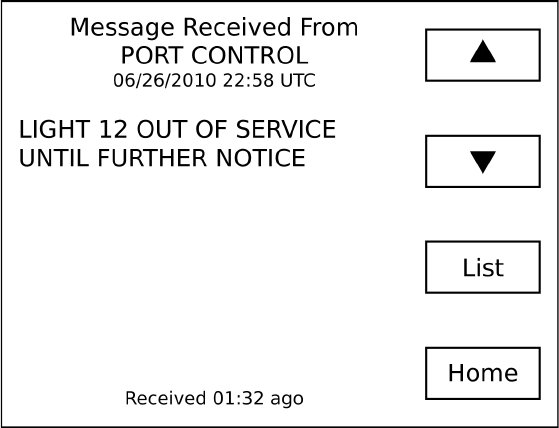
Safety Message Display
The message display screen is shown when you select a message
from the safety message list. The sender and full text of the message
is shown on this screen.
When a safety message is first received, this screen is automatically
shown.
- 55 -

When the safety message screen is displayed, you can use the
following buttons:
▲ Display the previous safety message. This button is only
active if it is possible to scroll up.
▼ Display the next safety message. This button is only active
if it is possible to scroll down.
List Display the list of all safety messages.
Home Return to the situation display.
- 56 -
Fleet List
If targets have been marked as being members of your fleet, they
may be displayed in the fleet list. Use this list to view your fleet or
remove members from your fleet. To add a vessel to the fleet list, use
the Menu button on the target details screen.
Weather Reports
If meteorological / hydrographic messages are transmitted in your
area they will be placed in a list for you to review. The list shows the
latitude and longitude of each reporting station. By selecting a station
from the list you can display the full details received from the station.
GPS Position Display
You may display your current GPS position, course, heading (if
available) and speed over ground.
GPS Status Display
Use this display to view the signal strength of each GPS satellite in
view. All satellites in view are shown and those that are being
actively used are indicated with a dark bar. In addition, UTC time,
computed accuracy (HDOP) and 2D/3D status is shown.
- 57 -
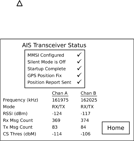
AIS Status Display
This screen displays information about your AIS transceiver's status.
In the box at the top of the screen the tick marks indicate the primary
operational state. If any items require attention they will be
indicated by
If this symbol is shown, the AISWatchMate is not transmitting your
vessel's AIS data.
- 58 -
!

A description of each item is shown below.
MMSI Configured You must configure your AISWatchMate with
a valid MMSI before transmission can occur.
See the Configuration section.
Silent Mode is Off One of three conditions:
1. You have enabled silent mode. See the
Silent Mode setup option under AIS
Transceiver Setup.
2. You are running on USB power only. It is
not possible to transmit when powered
solely by USB.
3. Your transceiver has been commanded by
a base station to enter “quiet mode”. You
cannot override this command. Normal
transmissions will resume automatically at
a later time.
Startup Complete There is a one minute startup time whenever
you switch on the AISWatchMate. During this
time, background noise levels are determined.
GPS Position Fix Your AISWatchMate must have a valid GPS
fix in order to transmit. See the GPS Status
screen to determine satellite signal strengths.
If you are unable to achieve a GPS fix due to
low satellite strength, consider using an
optional accessory external antenna or
moving the unit or antenna. Always place
GPS antennas as far away from other
antennas, such as radar antennas, as possible.
- 59 -

Position Report Sent Indicates that the last scheduled position
report was sent. It is normal to occasionally
miss a position report when operating in busy
areas.
Frequency The radio frequency assigned to each channel.
You cannot change this value.
Mode The operating mode for each each channel.
You cannot change this value.
RSSI The background noise level for each channel.
This is for informational purposes.
Rx Msg Count The number of AIS messages that have been
successfully received on each channel.
Tx Msg Count The number of AIS messages that have been
successfully transmitted on each channel.
CS Thres The carrier-sense threshold for each channel.
This value is automatically adjusted and is for
informational purposes.
- 60 -
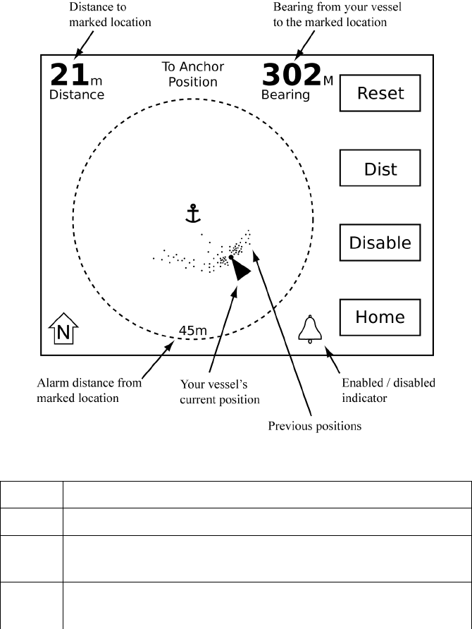
Using the Anchor Watch
The anchor watch may be used to sound the alarm if your vessel
moves outside a preset circle. To use the anchor watch, follow these
steps:
1. Prior to anchoring, select “Anchor Watch” from the main
menu.
2. Adjust the size of the preset circle by using the Dist button.
This button determines the alarm distance from your anchor
(or radius) of the circle. The distance may be changed at any
time.
3. Press the Set button to mark your anchor location as you drop
your anchor and when it hits the bottom. This automatically
enables the alarm at your preset distance.
When the Anchor Watch screen is displayed, the bearing from your
vessel to the marked anchor location is shown. It is shown in either
Magnetic or True, depending on your Preference Settings which can
be adjusted in setup mode.
The distance between your vessel and the marked anchor location is
also displayed. This distance may be in feet or meters depending on
your Preference Settings.
The position of your vessel periodically within the last 24 hours is
shown as a dot. These positions are useful to show your vessel
swinging on its anchor. They are automatically removed when you
reset your anchor position or shut off your AISWatchMate.
- 61 -
Use the following buttons from the Anchor Watch screen:
Reset Reset the anchor location to your current position.
Dist Adjust the alarm distance (radius of the circle).
Enable
Disable
Turn the alarm on or off.
Home Return to the situation display.
Note: If the alarm is enabled, it will remain active.
- 62 -
Use of Heading Data
If heading data is available, your vessel is shown oriented by its
heading. If heading data is not available, your vessel is shown
oriented by its course and it is likely it will not correspond accurately
with reality. It is also normal for the orientation of your vessel to
fluctuate or point north in this circumstance.
Effect of GPS Antenna Reference Location
The Anchor Watch determines the position of the bow of your vessel
and uses it when marking your anchor location and also when
plotting your current vessel position. This increases accuracy as your
vessels swings around its anchor. However, this can only be done if a
heading sensor is connected to your AISWatchMate. It also requires
that your vessel's GPS antenna reference location (A, B, C, D) has
been configured using the AIS Transceiver Setup screen.
If a heading sensor is not connected or your GPS antenna reference
location is not configured, then the Anchor Watch uses the position
of your GPS antenna for both marking the anchor location and vessel
positions.
Important note: GPS smoothing may cause the display of your
position on the anchor watch to be less responsive. This can be
adjusted with the GPS Smoothing setup option.
Auto Clear
If the Anchor Watch alarm is not enabled and your vessel has moved
a significant distance from its previously marked anchor location, the
Anchor Watch automatically clears the previously marked location.
This allows you to more easily set a new anchor watch using the
procedure above each time you move to another location.
- 63 -

Icon Meanings Within Anchor Watch
Your vessel. The reference position of your GPS antenna is not
known or heading data is not available.
Your vessel. The dot at the bow indicates that your position is
referenced to the bow of your vessel.
The alarm is enabled and will sound if your vessel moves outside
the circle. Adjust the distance from your marked anchor location
by using the “Dist” button.
Note: To prevent nuisance alarms, the alarm does not sound
immediately when your vessel moves outside the circle. It may
take several seconds for the Anchor Watch to confirm your
vessel's position is outside the circle before sounding the alarm.
The alarm is disabled.
The Anchor Watch screen is always displayed North-Up. This
cannot be changed.
- 64 -
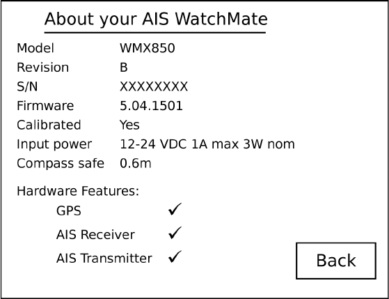
Displaying Information About your AIS WatchMate
You can display the following information by selecting About your
AIS WatchMate from the display settings menu.
This information is provided for reference and technical support
purposes.
- 65 -

Target Filters
There are several filters which allow you to control which targets are
included in the target list and may be displayed. These give you the
ability to limit the target list and are most useful when operating in
areas with large amounts of vessels. Any filter can be turned off. If
all filters are turned off, then all possible targets are included in the
target list and all targets may trigger alarms.
When a target is filtered, it is not shown in the target list. No
alarms are triggered for filtered targets.
Target range filter Specifies the maximum range (distance in
nautical miles) for targets. Any targets farther
away than this distance will not be included in
the target list and will not trigger alarms.
This allows you to only view and trigger alarms
for targets that are “nearby” and filters out
targets that are farther away.
It is not recommended to set this value too
low since it may filter out all targets and
alarms.
Target speed filter Specifies the minimum speed (in knots) a target
must be moving. Any targets moving slower
than this speed will not be included in the target
list and will not trigger any alarms.
This allows you to eliminate from the target list
and prevent alarms for targets which are
- 66 -

stationary or moving very slowly. It is most
useful when there are large numbers of
anchored or moored vessels in your operating
area.
It is not recommended to set this value too
high since it may filter out all targets and
alarms.
Target CPA filter Specifies the maximum CPA allowed for a
target to be visible. All targets with a CPA
greater than this value will be filtered and not
shown. You can also select “Non-Converging”
which causes all targets which are not
converging (they have no CPA) to be filtered.
This allows you to eliminate from the target list
all targets which are either moving away from
you or will pass at a safe distance. It is most
useful when there are many moving targets.
Target TCPA
filter
Specifies the maximum TCPA allowed for a
target to be visible. All targets with a TCPA
greater than this value will be filtered and not
shown.
This allows you to eliminate from the target list
all targets which are not going to be nearby
soon. It is most useful when there are many
moving targets.
- 67 -
Target Alarms
There are two types of target alarms provided by the AISWatchMate.
They are called Guard Alarm and CPA Alarm. Each alarm applies
independently to each target. This means that alarms may be silenced
for some targets but will still remain active for other targets.
When an alarm is sounded, the display immediately shows the target
that has triggered the alarm. Pressing the Mute button silences the
alarm and all subsequent alarms for that target only. Other targets
may still trigger alarms. The idea is that you have acknowledged the
target and are now aware of its presence and/or collision potential.
The AISWatchMate will continue to monitor and update the display
for that target, but unless you turn the alarm back on for that
target it will not cause any other alarms.
To turn the alarm back on for a target, use the Enable Alarms from
the target menu. The display briefly shows whether alarms are muted
or enabled for each target whenever the Enable or Disable Alarms
menu item is selected.
If more than one target is simultaneously triggering alarms, then the
highest priority target is shown first. Once you have pressed the
Mute button for that target, the next highest priority target is
immediately shown and the alarm sounds again. When you press the
Mute button for the last (or only) target with an alarm triggered, the
display remains showing that target.
When an alarm is triggered for a target, the target is automatically
displayed and the reason for the alarm is blinking (eg. RNG for a
guard alarm and CPA for a CPA alarm). The blinking stops when the
alarm is muted or the target is no longer triggering an alarm.
- 68 -
Guard Alarm
The simplest type of target alarm is the guard alarm. It is triggered
whenever a target is within range of the alarm setting. It works
similar to a radar guard alarm. You select the range for the alarm and
if any vessel is currently within that range, in any direction around
you, the alarm is triggered.
When a guard range is selected, a guard alarm is only triggered for a
target when it is currently within the guard range and is not based on
whether the target will enter the guard range at some time in the
future.
You can also select to have all targets trigger an alarm regardless of
their range by setting the guard alarm to “ALL” rather than a specific
range. When this setting is enabled the alarm will sound when data is
first received for each target. This alarm setting is most useful
offshore or anywhere targets are expected to be encountered
infrequently. It is used to notify the user that an AIS target exists
“out there” even if the target poses no collision risk.
When a guard alarm is triggered the target is immediately displayed.
Press the Mute button to silence the alarm. No further alarms will be
triggered for this target. However, if you still wish to have a
subsequent CPA alarm for this target, use the Enable Alarms menu
item to re-enable alarms for the target. When you re-enable alarms,
the guard alarm is not sounded again. Only subsequent CPA alarms
will be re-enabled. The reason is you have been alerted to the target's
presence and acknowledged it but have now indicated you also
would like to have an alarm triggered if a collision risk exists.
Important note: Guard alarms will not be triggered if GPS
information is unavailable for your vessel. Guard alarms which
specify a range require GPS data for your vessel. These alarms will
not be triggered if GPS data is not available. However, if you set the
- 69 -

guard alarm to “ALL”, then the alarm will sound regardless of
whether GPS data is available or not. You can use this feature if you
have not connected the AISWatchMate to a GPS but wish to be alerted
when targets are present. This is the only alarm setting that will
work when GPS data for your vessel is not available.
CPA Alarm
A CPA alarm is triggered when a target meets the criteria you have
established. When a CPA alarm occurs, the target that caused the
alarm is displayed. Press the Mute button to silence the alarm. No
further alarms will be triggered for this target. However, if you wish
to re-enable CPA alarms for this target again, use the Enable
Alarms menu item. Naturally, if the target is still within the
parameters established for triggering a CPA alarm, the alarm will
immediately sound again for that target!
There are several settings that control when a target triggers a CPA
alarm:
CPA alarm The distance (in nautical miles) which causes a CPA
alarm to be triggered. If a target has a CPA of this
value, or less, an alarm will be triggered for that
target unless the alarm is suppressed by any of the
other settings described below.
This allows you to generate an alarm for any target
that is predicted to come “too close”.
CPA alarm –
time
The time (in minutes) of when the CPA will occur.
If the CPA time is greater than this value then no
CPA alarm will be triggered for this target.
- 70 -

This allows you to suppress alarms for targets which
are predicted to come close but not for a long period
of time.
CPA alarm –
target speed
The speed (in knots) which the target must be
moving in order to trigger a CPA alarm. If the target
is moving at less than this speed then no CPA alarm
will be triggered for this target.
This allows you to suppress alarms for targets which
are either stationary (anchored or moored) or are
moving very slowly (drifting, fishing, etc.).
CPA alarm –
your speed
The speed (in knots) that your own vessel must be
moving in order to allow CPA alarms. If your vessel
is moving at less than this speed then no CPA alarms
will be triggered for any targets.
This allows you to suppress alarms when your vessel
is anchored, moored, drifting, fishing, etc. It can be
used to turn off alarms automatically when you stop
or slow down and eliminates the need to turn the
AISWatchMate off or select the Anchored profile.
Important note: CPA alarms are not triggered if GPS
information is not available for your vessel.
- 71 -
Profiles
To organize the filter and alarm settings there are four “profiles”.
These allow you to quickly switch between various settings when
your situation changes. This is done by selecting the active profile
from the main menu on the situation display. Each profile is provided
with a default value for its settings, but you can change these values
and they will remain at your selected settings until you change them
again, even after you turn the unit off. You can switch profiles or
make changes to the settings associated with a profile at any time.
To change the settings associated with a profile, you must select the
profile first and then enter setup mode.
Harbor
This profile is intended to be used when navigating within a harbor
where frequent shipping and AIS traffic is expected.
Coastal
This profile is intended to be used when navigating along a coast or
shore where occasional shipping and AIS traffic is usually
encountered.
Offshore
This profile is intended to be used when navigating in open ocean
situations where little shipping and AIS traffic is expected.
Anchor
This profile is intended to be used when anchored or moored and
when you only want to view AIS information from other vessels. By
default, no alarms are enabled in this profile.
- 72 -

Setup Mode
Setup mode is entered by selecting Setup from the main menu on the
situation display. In setup mode the list of available setting groups
are displayed. Scroll through the list and select the setting group you
wish to change. You may then follow the same procedure to select
the specific setting you wish to change and a pop up box is displayed
with the available options for that setting.
Note: Filter and alarm settings are associated with a profile and only
the settings in the currently active profile may be changed. If you
wish to change the settings for a different profile, you must select the
profile before entering setup mode.
While the settings screen is displayed, you can use the following
buttons:
▲ Highlight the previous setting. This button is only active if
it is possible to scroll up.
▼ Highlight the next setting. This button is only active if it is
possible to scroll down.
Select Change the highlighted setting.
Home Save any changes and return to the situation display.
Any changes you make to settings are stored permanently until you
change them again, even if you turn off the power.
Target List Settings
Data display in
target list
Choose whether to display each target's SOG
or CPA in the target list.
- 73 -

The default is to display CPA in the target
list.
However, if you are not using the target
speed filter you may find it useful to display
the target's speed instead.
Sort targets by
priority
Displays targets sorted by their priority. A
target's priority is based on its CPA, time
until CPA (TCPA), range, and speed. You
can choose to disable this setting and targets
will be displayed in the order in which data
was first received from a target.
Inactive target
display time
Selects how many minutes to display a target
that is no longer being received.
Alarm Settings
Lost position alert Choose whether to enable or disable an alert
which sounds if your vessel's position
becomes unavailable for more than 15
seconds.
This alert sounds the alarm with a single
short beep and may indicate a problem with
GPS reception, your GPS device, or wiring.
When position information is not available
for your vessel, computed information about
each target (range, bearing, CPA, TCPA) are
not displayed.
- 74 -

In addition, if position information is not
available a message is shown on the situation
display, target list, and target display.
Note: If your vessel's position is not
available then alarms will not be triggered.
Safety message
handling
Choose whether to enable or disable an alert
which sounds when a safety message is first
received.
This alert sounds the alarm with three short
beeps.
If the same message is received again it does
not sound the alarm.
NMEA device alerts Choose whether to display NMEA device
alerts (sentence ALR). When this setting is
enabled, each alert sounds the alarm with a
single short beep and is displayed in a
message box. When a NMEA device alert
message is displayed, press the Confirm or
Ignore button. See the section on NMEA
Device Alerts and transceivers in this
document.
Alarm mode Choosing Internal-only will only sound the
internal alarm. External-only requires an
external alarm, buzzer or indicator be
connected. You can also select to have both
sound simultaneously.
Caution: Audible alarms will not occur if
- 75 -

you select External-only and an external
alarm is not fitted.
Test the alarm Allows you to test the internal or external
alarm to ensure it is working properly.
Navigation Settings
Course and heading
mode
Select how to display course and heading
data for targets. This also affects how your
vessel's heading is shown on the situation
display. You may choose between True or
Magnetic.
Bearing to target
mode
Select how to display bearings to targets. The
default is magnetic and is recommended for
easy visual identification of targets using a
compass and/or binoculars. However, if you
prefer you may select true or relative
bearings.
Relative bearings show the target's bearing
relative to your own vessel's heading (eg.
000R is directly ahead of you, 180R is
directly behind, 270R is off your port beam,
and 090R is off your starboard beam).
To display relative bearings, heading data for
your vessel should be available. This data
may be output from a heading sensor or
autopilot. Consult the manual for these
devices. The AISWatchMate accepts NMEA
0183 sentences HDG, HDT, or HDM for
- 76 -

heading data.
Note: If heading data is not available then
relative bearings will be shown relative to
your course rather than your heading.
Note: If magnetic variation is not provided
by your GPS or heading sensor then magnetic
bearings will be shown as true.
Default display
orientation
Select the orientation (Heading-Up or North-
Up) you wish to use by default. This
orientation is used if a profile doesn't
override this setting. This allows you to
indicate that you wish all profiles to use a
particular orientation except one that
specifies otherwise. For example, always use
Heading-Up except when anchored when you
want to use North-Up.
GPS Smoothing The setting enables a GPS smoothing
function which enhances position and course
stability. This setting is suitable for most
situations. However, when this setting is
enabled you may find the anchor watch to be
less responsive.
GPS SBAS (WAAS,
EGNOS)
Use this setting to enable or disable GPS
differential corrections received from
Satellite Based Augmentation Systems such
as WAAS, EGNOS, MSAS and GAGAN.
Simulation mode Use this setting to start or stop a simulation
of GPS and AIS targets for demonstration
- 77 -

purposes. When the simulation is running,
actual GPS positions and targets are not
displayed.
Display Settings
Brightness Adjusts the brightness of the display and
buttons. You can also adjust the brightness by
momentarily pressing the power button.
Contrast Adjusts the display contrast.
Turn display off
when idle
Select the number of minutes after which the
display is turned off. If the display is off and
a target or message is received the display is
automatically turned back on.
The display is only turned off when there are
no targets and no messages.
To turn the display back on manually, press
any button.
Select “Disable” to leave the display on at all
times.
When enabled, this feature reduces power
consumption when there are no targets or
messages to display.
About your AIS
WatchMate
Displays information containing your product
model, serial number, version and other data.
See the section Displaying Information About
Your AIS WatchMate for more details.
- 78 -

Preference Settings
Language Select the language you wish to use.
Date format Select between MM/DD and DD/MM. This
setting determines how a target's ETA is
displayed.
Metric or imperial Select the units (metres or feet) to use for
displaying target dimensions.
AIS Transceiver
Silent Mode Enable or disable the AIS transmitter. This
feature may be used in situations where you
do not wish to transmit your vessel data.
Your vessel AIS
details
Configure your vessel details for
transmission to other vessels via AIS. The
AISWatchMate will not transmit until you
have configured your vessel details. See the
Configuration section for more details.
I/O Port Settings
NMEA input Select the type of device connected to supply
input on this port. Choose from NMEA 4800
baud or NMEA 38400 baud.
NMEA output Select the type of data to output on this port.
Choose from NMEA only at 4800 baud, AIS-
only and NMEA+AIS at 38400 baud.
Additional Settings
Reset all settings Resets all settings to the original factory
- 79 -

values. Any settings you have changed will
be reset and you will lose any changes you
have made.
When you select this setting a warning is
displayed. To continue and reset all settings,
choose “Yes” to “Are you sure?” and press
“OK”.
When you answer “Yes” or “No”, a message
is briefly displayed confirming your choice.
Settings Associated with Each Profile
The following settings are associated with a profile selection. Each
profile (Harbor, Coastal, Offshore, and Anchor) has it's own value
for each of these settings. The setup screens display the settings
associated with the currently active profile. The name of the current
profile is shown on the top line of the screen. Any changes to these
settings affect the current profile only.
Hint: To change the settings for a profile you must activate the
profile first. Do this from the main menu on the situation display
before entering setup mode.
Display orientation Choose the orientation of the display when
this profile is activated. The orientation can
be Heading-Up, North-Up or Use Default. If
you select Use Default then the default
display orientation (determined in the Display
- 80 -

Settings Group) will be used. This allows you
to override the default for one or more
profiles, for example setting the default to
Heading-Up but overriding it to be North-Up
when anchored.
Target speed filter This specifies the minimum SOG (in knots)
that a target must be moving to be included in
the target list. Targets moving slower than
this speed will be filtered from the target list
and will not appear.
Use this filter to eliminate slow or stationary
targets from the target list. Alarms are not
triggered for filtered targets.
The total count of filtered targets is displayed
on the situation display.
Selecting “OFF” disables the target speed
filter.
If this setting is higher than the “CPA alarm -
Target Speed” setting a warning is displayed
to indicate you may be filtering more targets
than you intend.
It is not recommended to set this value too
high since it may filter out all targets and
alarms.
Target range filter This specifies the maximum range (distance
in nautical miles) for a target to be included
- 81 -

in the target list. Targets farther away will be
filtered from the target list and will not
appear.
Use this filter to eliminate distant targets
from the target list. Alarms are not triggered
for filtered targets.
The total count of filtered targets is displayed
on the situation display.
Selecting “OFF” disables the target range
filter.
It is not recommended to set this value too
low since it may filter out all targets and
alarms.
Target CPA filter This specifies the maximum CPA value a
target can have and still be displayed. Any
targets with a CPA greater than this value
will be filtered.
Use this filter to eliminate targets which will
pass at a safe distance. Alarms are not
triggered for filtered targets.
The total count of filtered targets is displayed
on the situation display.
Selecting “OFF” disables the target CPA
filter.
- 82 -

Selecting “All Non-converging” indicates
that all targets that do not have a CPA
(meaning they are not on a converging
course) will be filtered.
If this setting is lower than the “CPA alarm -
Target Speed” setting a warning is displayed
to indicate you may be filtering more targets
than you intend.
Target TCPA filter This specifies the maximum TCPA value a
target can have and still be displayed. Any
targets with a TCPA greater than this value
will be filtered.
Use this filter to eliminate targets which will
not be nearby soon. Alarms are not triggered
for filtered targets.
The total count of filtered targets is displayed
on the situation display.
Selecting “OFF” disables the target TCPA
filter.
If this setting is lower than the “CPA alarm -
Time” setting a warning is displayed to
indicate you may be filtering more targets
than you intend.
Guard alarm range This specifies a range in nautical miles.
Targets within this range will trigger a guard
alarm regardless of whether a collision risk
- 83 -

exists.
Guard alarms are most useful when operating
where few targets are expected to be
encountered and you wish to be notified there
is “somebody out there”.
Selecting “OFF” disables the guard alarm.
Selecting “ALL” indicates that all targets
regardless of their range will trigger the guard
alarm.
Important note: “ALL” is the only alarm
setting that operates without GPS input.
CPA alarm Triggers a CPA alarm for any target which
will come this distance or closer to your
vessel (in nautical miles).
An alarm will not be triggered if the target
doesn't also meet the specifications of the
other CPA alarm settings described below.
Selecting “OFF” disables the CPA alarm.
CPA alarm - Time This value specifies the maximum amount of
time (in minutes) that a target's CPA must
occur for it to trigger an alarm. If a target has
a CPA which is “too close” but the TCPA is
greater than this value, no alarm will be
triggered.
- 84 -

This allows you to indicate that you only
want alarms for targets which pose a risk of
collision in the “near future”.
Selecting “OFF” allows a CPA alarm to be
triggered regardless of the time until CPA if
it also meets the specifications of the other
CPA alarm settings.
This setting is only available if the “CPA
alarm” setting is not set to “OFF”.
CPA alarm - Target
Speed
This value specifies the minimum SOG (in
knots) that a target must be moving for it to
trigger a CPA alarm. If a target meets the
other specifications for a CPA alarm but is
not moving at least this fast, no alarm will be
triggered.
This setting allows you to indicate that you
don't want alarms for stationary or slow
moving targets.
Selecting “OFF” allows a CPA alarm to be
triggered regardless of the target's speed if it
also meets the specifications of the other
settings.
If this setting is lower than the “Target speed
filter” setting a warning is displayed to
indicate you may be filtering more targets
than you intend.
- 85 -

This setting is only available if the “CPA
alarm” setting is not set to “OFF”.
CPA alarm - Your
speed
This value specifies the minimum SOG (in
knots) that your vessel must be moving for a
CPA alarm to be triggered by other vessels. If
a target meets the other specifications for a
CPA alarm but your vessel is not moving at
least this fast, no alarm will be triggered.
This setting allows you to indicate that you
don't want alarms when you are stationary or
moving slowly.
Selecting “OFF” allows a CPA alarm to be
triggered regardless of the target's speed if it
also meets the specifications of the other
settings.
This setting is only available if the “CPA
alarm” setting is not set to “OFF”.
- 86 -

Built-in Integrity Test (BIIT)
The AISWatchMate continuously monitors its transceiver
performance. If it detects an error condition you will be notified with
a message box and the alarm will beep briefly. For certain messages
you are able to press the Confirm button to acknowledge the situation
and prevent the message from reappearing. However, this is not
possible with all messages and some will reappear whenever the
error condition is detected. An example message box is shown
below.
Built-in Integrity Test
ID: 001
AIS RECEIVER IS NOT FUNCTIONING
Some possible error conditions are:
AIS RECEIVER CH n: SYNTHESIZER LOST LOCK
AIS RECEIVER IS NOT FUNCTIONING
AIS TRANSMITTER ERROR: reason
VSWR LEVEL: CHECK ANTENNA CONNECTIONS
ERROR DETECTED WITH INTERNAL GPS
DEVICE IS RUNNING UNDER USB POWER. SOME
FUNCTIONALITY IS RESTRICTED
- 87 -

Device Alerts
The AISWatchMate will display device alerts (sentence $xxALR)
received from other instruments. These alerts may indicate
operational status or problems. When a device alert arrives, the
message associated with it is displayed and you are given the
opportunity to send a confirmation back to the device that generated
the alert. This tells the device that you have acknowledged the
situation. The specific types of alerts and messages are determined
by the attached devices. Please consult the manuals for the other
devices for details about each message.
When a message arrives, it is displayed automatically and the alarm
is beeped briefly to notify you. Press the Confirm or Ignore button
to dismiss the message. If you press the confirm button, an
acknowledgment message (sentence $xxACK) is sent back to the
device containing the message ID.
An example message (the message content is supplied by the other
device and will vary from device to device):
NMEA Device Alert
ID: 003
HDG: HEADING SENSOR INACTIVE
- 88 -

Troubleshooting
Problem Solutions
Display shuts off Check to see if the “Turn display off when
idle” setting is enabled.
Won't shut off when I
press the power button
Press and hold the power button for 2
seconds.
CPA alarm doesn't
sound
1. Check the profile you have selected by
looking on the situation display or
choosing the Profile item from the main
menu on the situation display.
2. Use setup to verify the CPA alarm
parameters for the current profile.
3. Check “CPA alarm” setting to make sure
it is enabled and set to a value greater than
the range of the target in question.
4. Ensure the “CPA alarm - Time” setting
isn't set too low.
5. Check the “CPA alarm – Target speed”
and “CPA alarm – Your speed” settings.
Alarms sounds for
every target
Use setup to verify the “Guard alarm
range” setting for the current profile. If this
setting is “ALL” then every target will
trigger an alarm.
- 89 -
Warranty – North America
The AISWatchMate is warranted, when properly installed and used, to be free
from defects in materials or workmanship for one year from the date the product
was purchased by the first retail customer. This warranty applies to the original
retail purchaser only and is not transferable. Within this period, Vesper Marine
will, at its sole option, repair or replace any components which fail in normal use.
Repairs or replacement will be made at no charge for parts or labor, provided that
the customer shall be responsible for any transportation costs. This warranty does
not cover failures due to abuse, misuse, accident, improper installation,
unauthorized alterations or repairs, shipping damage, wear and tear, or corrosion.
This warranty is void if the product's external housing has been opened, the serial
number or other labels have been removed or altered, the specified input voltage
has been exceeded, or the external alarm maximum switched current has been
exceeded.
Vesper Marine retains the exclusive right to replace the unit with a factory
reconditioned unit or a new unit at its sole discretion. Where a replacement is
provided the original product becomes the property of Vesper Marine and the
warranty will remain from the original purchase date.
THE WARRANTIES AND REMEDIES CONTAINED HEREIN ARE EXCLUSIVE
AND IN LIEU OF ALL OTHER WARRANTIES, WHETHER EXPRESS, IMPLIED
OR STATUTORY, INCLUDING ANY LIABILITY ARISING UNDER ANY
WARRANTY OF MERCHANTABILITY OR FITNESS FOR A PARTICULAR
PURPOSE, STATUTORY OR OTHERWISE. THIS WARRANTY GIVES YOU
SPECIFIC LEGAL RIGHTS, WHICH MAY VARY FROM STATE TO STATE.
IN NO EVENT SHALL VESPER MARINE BE LIABLE FOR ANY INCIDENTAL,
SPECIAL, INDIRECT, OR CONSEQUENTIAL DAMAGES, WHETHER
RESULTING FROM THE USE, MISUSE OR INABILITY TO USE THE PRODUCT
OR FROM DEFECTS IN THE PRODUCT. SOME STATES DO NOT ALLOW THE
EXCLUSION OF INCIDENTAL OR CONSEQUENTIAL DAMAGES, SO THE
ABOVE LIMITATIONS MAY NOT APPLY TO YOU.
Vesper Marine retains the exclusive right to repair or replace the product or offer a
full refund of the purchase price at its sole discretion. SUCH REMEDY SHALL
BE YOUR SOLE AND EXCLUSIVE REMEDY.
- 90 -
Warranty - Australia and New Zealand
The AISWatchMate is warranted, when properly installed and used, to be free
from defects in materials or workmanship for one year from the date the product
was purchased by the first retail customer. This warranty applies to the original
retail purchaser only and is not transferable. Within this period, Vesper Marine
will, at its discretion, repair or replace any components which fail in normal use.
Repairs or replacement will be made at no charge for parts or labour, provided that
the customer shall be responsible for any transportation costs. This warranty does
not cover failures due to abuse, misuse, accident, improper installation,
unauthorized alterations or repairs, shipping damage, wear and tear, or corrosion.
This warranty will not apply if the product's external housing has been opened, the
serial number or other labels have been removed or altered, the specified input
voltage has been exceeded, or the external alarm maximum switched current has
been exceeded.
This warranty is in addition to all other rights available to the consumer under any
applicable statute and your statutory rights are not affected by this warranty.
Vesper Marine retains the exclusive right to repair or replace the unit or offer a full
refund of the purchase price at its sole discretion. In addition, Vesper Marine
retains the exclusive right to replace the unit with a factory reconditioned unit or a
new unit at its sole discretion. Where a replacement is provided the original
product becomes the property of Vesper Marine and the warranty will remain from
the original purchase date.
This warranty applies only to products supplied new to you by a stockist or Vesper
Marine and you have not bought the product for resale.
In no event shall Vesper Marine be liable for any incidental, special, indirect, or
consequential damages, whether resulting from the use, misuse or inability to use
the product or from defects in the product.
- 91 -
Warranty - European Union
The AISWatchMate is warranted, when properly installed and used, to be free
from defects in materials or workmanship for two years from the date the product
was purchased by the first retail customer. This warranty applies to the original
retail purchaser only and is not transferable. Within this period, Vesper Marine
will, at its discretion, repair or replace any components which fail in normal use.
Repairs or replacement will be made at no charge for parts or labour, provided that
the customer shall be responsible for any transportation costs. This warranty does
not cover failures due to abuse, misuse, accident, improper installation,
unauthorized alterations or repairs, shipping damage, wear and tear, or corrosion.
This warranty will not apply if the product's external housing has been opened, the
serial number or other labels have been removed or altered, the specified input
voltage has been exceeded, or the external alarm maximum switched current has
been exceeded.
This warranty is in addition to all other rights available to the consumer under any
applicable statute and your statutory rights are not affected by this warranty.
Vesper Marine retains the exclusive right to repair or replace the unit or offer a full
refund of the purchase price at its sole discretion. In addition, Vesper Marine
retains the exclusive right to replace the unit with a factory reconditioned unit or a
new unit at its sole discretion. Where a replacement is provided the original
product becomes the property of Vesper Marine and the warranty will remain from
the original purchase date.
This warranty applies only to products supplied new to you by a stockist or Vesper
Marine and you have not bought the product for resale.
In no event shall Vesper Marine be liable for any incidental, special, indirect, or
consequential damages, whether resulting from the use, misuse or inability to use
the product or from defects in the product.
- 92 -
Obtaining Warranty Service
To obtain warranty service please contact us. If you are unable to
contact Vesper Marine directly, then contact the dealer where you
purchased the unit.
You must have the original sales receipt. Online auction
confirmations are not acceptable as an original sales receipt.
Vesper Marine Ltd.
103 Westhaven Drive, St. Mary's Bay
PO Box 91164, Victoria Street West
Auckland 1142
New Zealand
Phone: +64 (0)9 950 4848
Fax: +64 (0)9 950 4085
www.vespermarine.com
support@vespermarine.com
Please contact Vesper Marine and obtain a return authorization
before sending your unit in for repair.
- 93 -