ViVOtech VIVOPAYKIOSKII Contactless Card reader User Manual Testing Software
ViVOtech, Inc. Contactless Card reader Testing Software
ViVOtech >
User manual

ViVOpay Kiosk II User Guide
631-0071-01 ViVOtech Proprietary Page 2 of 23
Copyright
Copyright© 2009, ViVOtech,® Inc. All rights reserved.
ViVOtech®, Inc.
451 El Camino Real
Santa Clara, CA 95050
Written and designed at ViVOtech, Inc.
This paper, as well as the software and hardware described in it, is furnished under license and
may be used or copied online in accordance with the terms of such license. The content of this
paper is furnished for information use only, is subject to change without notice, and should not
be construed as a commitment by ViVOtech, Inc. ViVOtech, Inc assumes no responsibility or
liability for any errors or inaccuracies that may appear in this document.
Except as permitted by such license, no part of this publication may be reproduced or
transmitted by electronic, mechanical, recording, or otherwise, or translated into any language
form without the express written consent of ViVOtech, Inc. ViVOtech, ViVOwallet, ViVOpay,
ViVOplatform, and ViVOadmin are trademarks or registered trademarks of ViVOtech®, Inc.
Warranty Disclaimer: The services and hardware are provided "as is" and "as-available," and
the use of the services and hardware is at its own risk. ViVOtech does not make, and hereby
disclaims, any and all other express or implied warranties, including, but not limited to,
warranties of merchantability, fitness for a particular purpose, title, and any warranties arising
from a course of dealing, usage, or trade practice. ViVOtech does not warrant that the services
or hardware will be uninterrupted, error-free, or completely secure.
January 2009
ViVOpay Kiosk II User Guide
631-0071-01 ViVOtech Proprietary Page 3 of 23
FCC Regulatory Compliance
Notices Class B Equipment
This equipment has been tested and found to comply with the limits for a Class B digital device
pursuant to Part 15 of the FCC Rules. These limits are designed to provide reasonable protection
against harmful interference in a residential installation. This equipment generates, uses, and can
radiate radio frequency energy and, if not installed and used in accordance with the instructions,
may cause harmful interference to radio communications. However, there is no guarantee that
interference will not occur in a particular installation. This device complies with part 15 of the FCC
rules. Operation is subject to two conditions: (1) This device may not cause harmful interference,
and (2) this device must accept any interference received, including interference that may cause
undesired operation.
If this equipment does cause harmful interference to radio or television reception, which can be
determined by turning the equipment off and on, the user is encouraged to try and correct the
interference by one or more of the following measures:
• Reorient or relocate the receiving antenna.
• Increase the separation between the equipment and the receiver.
• Connect the equipment into an outlet on a circuit different from that to which the receiver is
connected.
• Consult the dealer or an experienced radio/TV technician for help.
IC Compliance Warning:
Operation is subject to two conditions: (1) This device may not cause harmful interference, and (2)
this device must accept any interference received, including interference that may cause
undesired operation.
User Information
The user’s manual or instruction manual for an intentional or unintentional radiator shall caution
the user that changes or modifications not expressly approved by the party responsible for
compliance could void the user's authority to operate the equipment. In cases where the manual is
provided only in a form other than paper, such as on a computer disk or over the Internet, the
information required by this section may be included in the manual in that alternative form,
provided the user can reasonably be expected to have the capability to access information in that
form. [54 FR 17714, Apr. 25, 1989, as amended at 68 FR 68545, Dec. 9, 2003]
Cautions and Warnings
Caution: The unit should be mounted 1-2 feet away from other units. Can be
adjusted based on lane setup.
Caution: Danger of Explosion if battery is incorrectly replaced. Replace only with
same or equivalent type recommended by the manufacturer. Discard used batteries
according to the manufacturer’s instructions.
Warning: Avoid close proximity to radio transmitters which may reduce the ability of
the reader.

ViVOpay Kiosk II User Guide
631-0071-01 ViVOtech Proprietary Page 4 of 23
Table of Contents
1 Overview ......................................................................................................5
1.1 Features............................................................................................................ 5
1.2 Valid Card Types .............................................................................................. 5
1.3 Kiosk II Specifications....................................................................................... 6
2 ViVOpay Kiosk II Installation......................................................................7
2.1 Parts List........................................................................................................... 7
2.2 ViVOpay Kiosk II Installation............................................................................. 8
2.3 Mounting the ViVOpay Kiosk II External Antenna............................................. 8
2.4 Mounting the ViVOpay Kiosk II Controller....................................................... 10
2.4.1 Mounting the ViVOpay Kiosk II Controller Using Screws........................ 10
2.4.2 Mounting the ViVOpay Kiosk II Controller Using Mounting Tape............ 10
2.5 Attaching the Cables from the Antenna to the Controller................................ 11
2.6 Installing a SIM Card in the ViVOpay Kiosk II Controller ................................ 13
2.7 Using the ViVOpay Kiosk II to Make a Purchase............................................ 18
2.7.1 Presenting Cards, Fobs, or NFC Phones................................................ 18
2.7.2 Making a Purchase ................................................................................. 18
3 Installation Points .....................................................................................19
4 RF Interference..........................................................................................20
5 Troubleshooting........................................................................................ 21
6 Customer Support..................................................................................... 23

ViVOpay Kiosk II User Guide
631-0071-01 ViVOtech Proprietary Page 5 of 23
1 Overview
The ViVOpay Kiosk II is a compact stand-alone contactless reader designed to support
contactless transactions based on ISO 14443 Type A/Type B/MiFare compatible cards, fobs and
tags as well as NFC phones. The ViVOpay Kiosk II is comprised of a compact controller module
and an antenna module packaged individually with a separation of up-to 1-Meter. This design
approach allows the controller module to be easily installed within the cabinetry of a 3rd-party host
system and the customer-facing antenna to be installed with minimal footprint and effort.
The ViVOpay Kiosk II supports serial RS-232 host communication. The accompanying ViVOpay
serial interface protocol can be implemented with minimal effort. The ViVOpay Kiosk II is also
designed to support a wide input-power range while both data and power is provided via a single
cable thus minimizing the effort and complexity of installation and integration.
1.1 Features
• Supports ISO 14443 Type A, Type B, MiFare and NFC based contactless transactions
• 32-bit Microcontroller with ample memory capable of supporting future application upgrades
• Crypto data processing for contactless EMV cards
• RS-232 (9600, 19200, 38,400, 57,600, 115,200 baud) host interface
• Remote firmware updates over serial RS-232
• Small form-factor antenna flush-mounted on external cabinetry
• Internal mounted controller board with 1 Meter controller/antenna separation
1.2 Valid Card Types
ViVOpay Kiosk II supports the following contactless payment applications in the latest release of
firmware:
• PayPass ISO/IEC
• PayPass M/Stripe
• PayPass MChip
• PayPass MXI
• Maestro – must be configured
• RBS Application (M/Flex)
• VisaWave
• qVSDC/MSD
• JCB J/Speedy
• JCB Mobile/QuicPay
• American Express – ExpressPay
• Discover Zip
• ViVOwallet
• ViVONFC
• Mifare ePurse
ViVOpay Kiosk II User Guide
631-0071-01 ViVOtech Proprietary Page 6 of 23
1.3 Kiosk II Specifications
Hardware
MTBF 200,000 hrs.
Transmitter Frequency 13.56 MHz +/- 0.01%
Transmitter Modulation ISO 14443-2 Type A
Rise/Fall Time: 2-3 µsec. Rise, < 1 µsec fall
ISO 14443-2 Type B
Rise/Fall Time: < 2 µsec. each; 8% - 14% ASK
Receiver Subcarrier
Frequency 847.5 KHz
Receiver Subcarrier Data ISO 14443-2 Type A: Modified Manchester
ISO 14443-2 Type B: NRZ-L, BPSK
Typical Read Range 4-6 cm.
Physical
Antenna Height 75 mm (2.95 inches)
Antenna Width 60 mm (2.36 inches)
Antenna Depth 17.2 mm (0.67 inches)
Controller Height 105 mm (4.13 inches)
Controller Width 76.2 mm (3.00 inches)
Controller Depth 22.5 mm (0.88 inches)
Environmental
Operating Temperature -25° C to 70° C (-13° F to 158° F)
Storage Temperature -40° C to 85° C (-40° F to 185° F)
Operating Humidity 10% to 90% non-condensing
Operating Environment Indoor and outdoor use. Unit is water resistant.
Electrical
Reader Input Voltage 7.5 to 36 VDC, 3 Watts
ViVOpay Kiosk II User Guide
631-0071-01 ViVOtech Proprietary Page 7 of 23
2 ViVOpay Kiosk II Installation
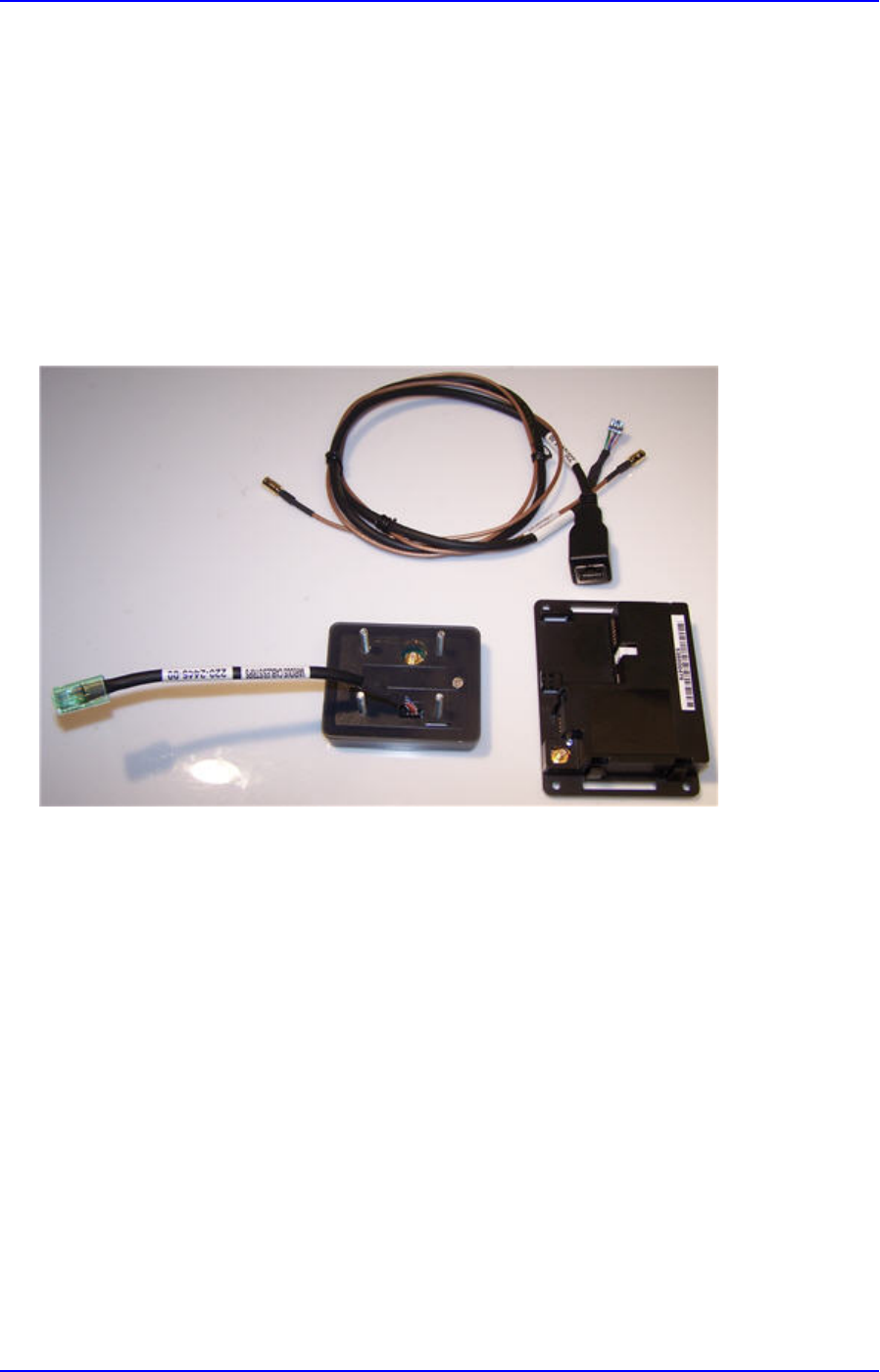
2.1 Parts List
Verify that you have the following hardware for the installation of the ViVOpay Kiosk II:
• ViVOpay Kiosk II Controller – 520-2305-00
• ViVOpay Kiosk II Antenna – 520-2304-00
• Antenna LED Power and data cable - 220-2457-00
• ViVOpay Kiosk II to ECR/POS Cable (14 pin) – application specific. This cable varies based
on the ViVOpay Kiosk II to be used.

ViVOpay Kiosk II User Guide
631-0071-01 ViVOtech Proprietary Page 8 of 23
2.2 ViVOpay Kiosk II Installation
This section provides information on how to install the ViVOpay Kiosk II unit on a Kiosk.
2.3 Mounting the ViVOpay Kiosk II External Antenna
Use the following instruction for mounting the external antenna on the exterior of the Kiosk:
Note: Verify the orientation of the ViVOpay Kiosk II Antenna before marking and drilling the holes.
The 2 larger holes should be located towards the top of the mounting location to ensure that the
ViVOpay Kiosk II antenna is oriented correctly so that the LED lights are at the top.
1. Using the Drill Template for the External Antenna (630-1056-00), locate and mark the four
4.4mm (0.173 inch) mounting holes.
2. Using the Drill Template for the External Antenna (630-1056-00 ), locate and mark the two
15.880 mm (0.625 inch) access holes (used for connecting the antenna power and the
LED power and data cable to the ViVOpay Kiosk II unit).
3. Drill the four 4.4 mm (0.173) mounting holes using a number 17 drill bit.
4. Drill the two 15.88 mm (0.625 inch) holes using a 5/8 drill bit.
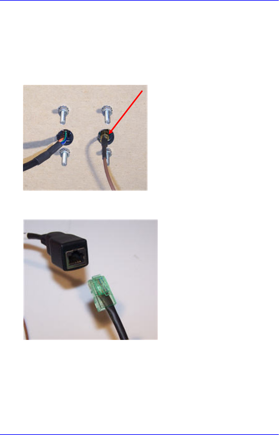
5. Remove the nuts from the four mounting screws.
6. Route the end of the cable (220-2457-00) with the RJ45 connector through the left 15.88
mm (0.625 inch) hole in to the Kiosk. Make sure that the front of the external antenna will be
properly oriented (not up side down) on the Kiosk before inserting the four screws into the
mounting holes.
ViVOpay Kiosk II User Guide
631-0071-01 ViVOtech Proprietary Page 9 of 23
7. Align the four screws with the mounting holes and attach the ViVOpay Kiosk II unit to the
outside surface. Make sure that the cable is routed cleanly through the left hole.
8. Use the four nuts to secure the ViVOpay Kiosk II unit to the outside surface of the Kiosk.
Make sure to tighten the nuts securely so that the ViVOpay Kiosk II unit does not move on
the outside surface of the Kiosk.
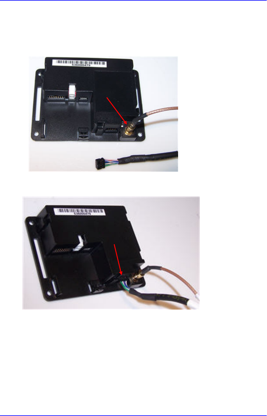
9. Attach the end of the cable with the SMB connector through the right 15.88 mm (0.625
inch) hole and attach it to the socket on the back of the ViVOpay Kiosk II Antenna. The
SMB connector pushes on to the socket on the Antenna.
10. Attach the RJ45 connector coming from the ViVOpay Kiosk II Antenna to the RJ45
receptacle on the 220-2457-00 cable.

ViVOpay Kiosk II User Guide
631-0071-01 ViVOtech Proprietary Page 10 of 23
2.4 Mounting the ViVOpay Kiosk II Controller
Note: The ViVOpay Kiosk II Controller must be mounted within 1 meter of the external antenna.
Make sure that the cable will be able to reach from the external antenna to the ViVOpay Kiosk
Controller if the external antenna is mounted of a surface that opens (such as a door) when the
antenna mounting surface is fully opened.
The ViVOpay Kiosk II installer must use their discretion when mounting the Controller.
If it acceptable, the installer can drill four holes for mounting the Controller if screw heads can
appear on the outside of the Kiosk. In this case, it would be advisable to use security screws to
prevent tampering with the screws.
If drilling additional holes on the outside of the Kiosk surface is not acceptable, the installer can use
double-sided tape to mount the Controller to any clean surface.
2.4.1 Mounting the ViVOpay Kiosk II Controller Using Screws
1. Position the ViVOpay Kiosk Controller on the interior of the II making sure that there is
sufficient room for the external antenna mounting surface to be fully opened.
63.50 [ 2.500 ]
2. Locate the four 4.4mm (0.173 inch) mounting holes by holding the ViVOpay Kiosk
Controller in position and mark the holes. The following diagram shows the spacing on the
holes to be drilled for mounting the ViVOpay Kiosk II Controller.
3. Drill the four 4.4 mm (0.173) mounting holes using a number 17 drill bit.
4. Use four screws and nuts to mount the ViVOpay Kiosk Controller to the Kiosk surface.
(Mounting screws are not provided and must be supplied by the installer.)
5. Tighten the nuts to hold the ViVOpay Kiosk II Controller in position so that it does not move.
2.4.2 Mounting the ViVOpay Kiosk II Controller Using Mounting Tape
1. Position the ViVOpay Kiosk II Controller on the interior of the Kiosk making sure that there
is sufficient room for the external antenna mounting surface to be fully opened.
2. Attach double-sided tape to the mounting surface.
3. Position the ViVOpay Kiosk II Controller over the mounting tape and gently apply pressure
to hold the Controller in position.
ViVOpay Kiosk II User Guide
631-0071-01 ViVOtech Proprietary Page 11 of 23
2.5 Attaching the Cables from the Antenna to the Controller
1. Attach the SMB end of the cable (220-2457-00) from the antenna to the ViVOpay Kiosk II
Controller.
2. Attach the other end of the cable (220-2457-00) from the antenna to the ViVOpay Kiosk II
Controller.

ViVOpay Kiosk II User Guide
631-0071-01 ViVOtech Proprietary Page 12 of 23
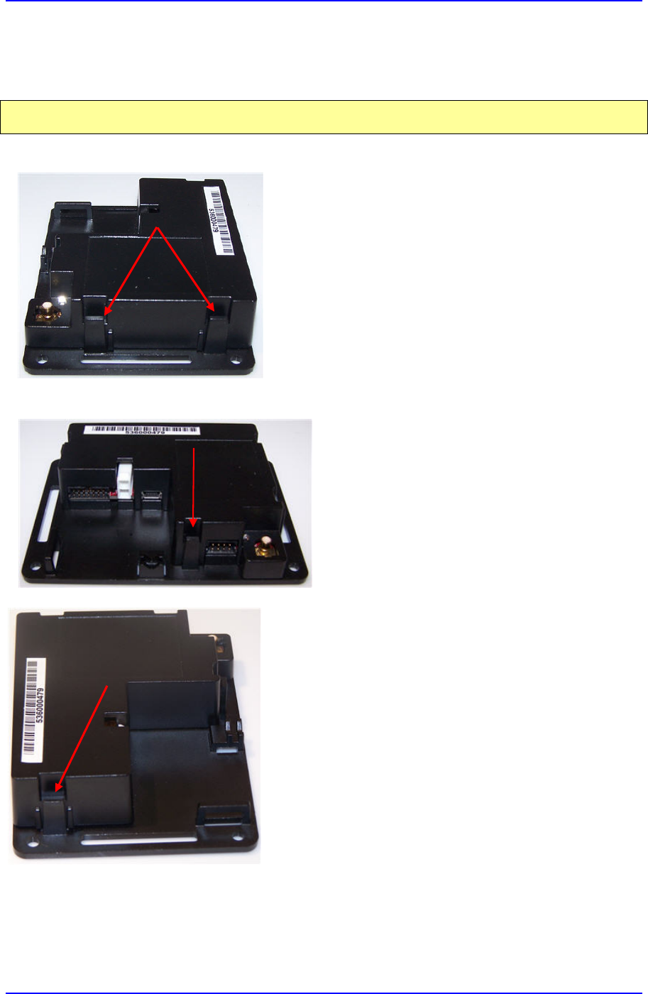
Note: Verify that the nub on the end of the data cable is facing towards the top of the
ViVOpay Kiosk II Controller (away from the mounting plate) before inserting the cable.
If the cable is installed incorrectly (up-side-down), it will apply the wrong polarity to the
LEDs and cause them to be damaged.
ViVOpay Kiosk II User Guide
631-0071-01 ViVOtech Proprietary Page 13 of 23
2.6 Installing a SIM Card in the ViVOpay Kiosk II Controller
Under certain circumstances, it might be necessary to install a SIM card in the ViVOpay
Kiosk II Controller.
Note: Opening the ViVOpay Kiosk II Controller unless directed to perform this operation by your
local Support personnel may void the warranty.
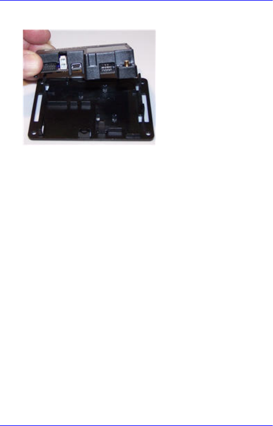
There are four clips that hold the ViVOpay Kiosk II Controller to the mounting base
• Two on one side
• One beside the cable receivers.
• One on the narrow end of the ViVOpay Kiosk II unit.

ViVOpay Kiosk II User Guide
631-0071-01 ViVOtech Proprietary Page 14 of 23
1. Gently pry all of the clips outward and remove the case from the base. The circuit
board should remain inside the case.
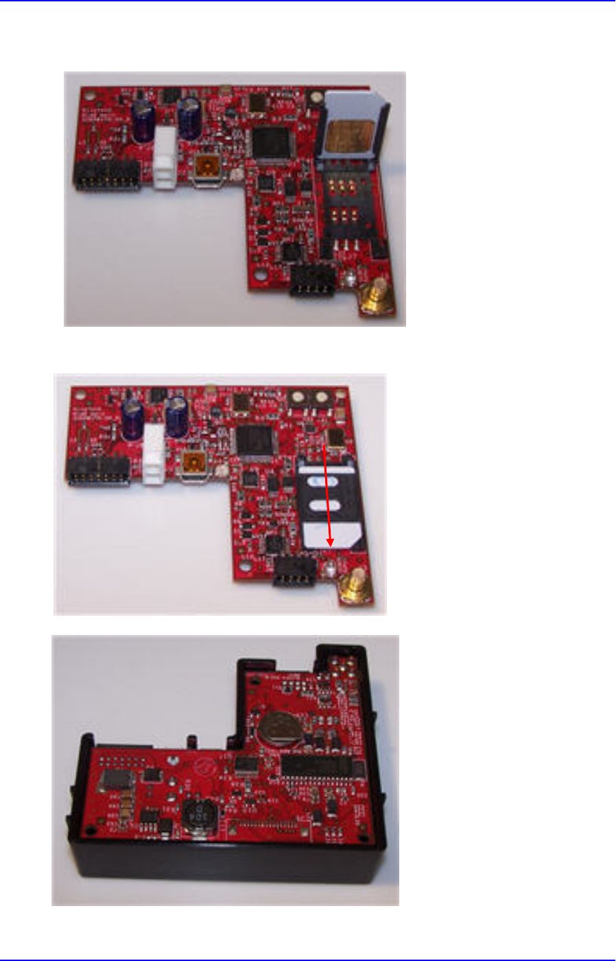
2. Turn the case over so that you can access the circuit board.
3. Use the cable receptacles to loosen the circuit board from the case and place the
circuit board flat on a non-conductive surface with the SIM holder facing up.

ViVOpay Kiosk II User Guide
631-0071-01 ViVOtech Proprietary Page 15 of 23
4. Slide the SIM holder away from the power and cable receptacles to loosen it from
the lock.
5. Raise the SIM holder so that you can install the SIM. Make sure that the SIM is
positioned so that the contacts on the SIM will make contact with the circuit board
when the SIM is lowered into position.
ViVOpay Kiosk II User Guide
631-0071-01 ViVOtech Proprietary Page 16 of 23
6. Insert the SIM into the SIM holder until it stops when it reaches the bottom of the
holder.
7. Gently lower the SIM holder and lock it into position by sliding it towards the cable
receptacles.
8. Reinstall the circuit board into the case.
ViVOpay Kiosk II User Guide
631-0071-01 ViVOtech Proprietary Page 17 of 23
9. Reattach the holder to the base making sure that all four clips lock in place.
10. Installation of the SIM in the ViVOpay Kiosk II Controller is complete.

ViVOpay Kiosk II User Guide
631-0071-01 ViVOtech Proprietary Page 18 of 23
2.7 Using the ViVOpay Kiosk II to Make a Purchase
2.7.1 Presenting Cards, Fobs, or NFC Phones
Your new ViVOpay Kiosk II allows for credit/debit card purchases using the new contactless
technology.
Present the card/fob/phone in close proximity to the front portion of the reader. Present the
card/fob/phone so that maximum surface area is parallel to the antenna as shown below. The
reader should beep and all four green LEDs should illuminate briefly to indicate a successful test.
This tests the reader's ability to read the RFID test card. If unsuccessful, there will be no reaction
from the reader. If you use a test card and the ViVOpay reader is attached to the ViVOpay Kiosk II
control unit, a dummy transaction can be tested. The transaction will not be authorized and will
come back with a response, but will at least test for end-to-end connectivity.
2.7.2 Making a Purchase
1. After the transaction has been entered on the ViVOpay Kiosk II control panel, the customer
should present their card/fob/phone in close proximity so that maximum surface area is
parallel to the antenna.
2. A single beep and all four LEDs briefly flashing indicates the card/fob/phone has been read
correctly.

ViVOpay Kiosk II User Guide
631-0071-01 ViVOtech Proprietary Page 19 of 23
3 Installation Points
• Although the ViVOpay Kiosk II Reader is designed to be mounted on to a metal surface and in
close proximity to any internal motors and electrical devices that may be operating inside the
Kiosk, it should be noted that in general, RFID readers can be susceptible to RF-induced
interference. Therefore, the ViVOpay unit is susceptible to RF and electromagnetic
interference. Therefore, it is important that the unit not be mounted next to or near (within 3 or 4
feet) large electric motors, computer UPS systems, microwave transmitters, anti-theft devices,
radio transmitters, communications equipment etc.
• All cables should be neatly tied with nylon cable-ties and routed in such a way that they are
inaccessible and invisible to customers. Cables should be clearly labeled at both ends to
indicate where they should be connected to.
• The ViVOpay unit should be tested after installation with a test card. An end-to-end transaction
should be run (the same as an actual purchase on the Kiosk). The ViVOpay Kiosk II should
register "Requesting Authorization". Even if the transaction is declined (as it should be with a
test card), it will prove connectivity all the way through the system. If possible the store
manager or some other responsible party should test each unit on a regular basis (perhaps at
the start of each day or at least once per week) with a test card to ensure continued operation
and functionality. If the ViVOpay Kiosk II is rebooted on a regular basis (such as every night) it
is important to test the contactless reader as soon as possible afterwards in order to ensure
continued communication to the Kiosk.
• In order to minimize the incidence of non-functioning readers being reported, it is important that
ViVOpay Kiosk II distributors, technicians, and IT specialists servicing the retail locations are
made aware of how to troubleshoot the contactless readers. From past experience it has been
found that a large percentage of units that are returned to your local support representative
under the RMA process have been found to be in good working order. Some simple
troubleshooting while the reader is still installed can greatly reduce this number.
• If the ViVOpay unit does not appear to be working, verify that the unit is powered on.
- Make sure that the correct pins are utilized
- Make sure that the power provided is within the specified range of the ViVOpay Kiosk II
reader
- The correct polarity is observed

ViVOpay Kiosk II User Guide
631-0071-01 ViVOtech Proprietary Page 20 of 23
4 RF Interference
Q. Why do I need to know about RF interference?
A. Contactless payment uses radio frequency technology to send card data to a contactless
terminal reader.
Q. How can RF interference affect contactless payment?
A. RF interference can cause data errors. If RF interference is present, contactless payment
devices may operate intermittently or inconsistently.
Q. Where does RF interference come from?
A. Radio frequency interference (RFI) can originate from a wide number of sources at the
point-of-sale (POS). Some examples of sources of RF energy and RF interference include:
AM/FM radio and tv transmitters
2-way radios, pagers
Mobile telephones
Power lines, transformers
Medical equipment
Microwaves
Electromechanical switches
Many others
Q. What should I do if I suspect RF interference exists in my environment?
A. Begin by inspecting your environment for possible culprits for RF interference.
Q. Do equipment manufacturers test their devices for RF interference?
A. Electronic equipment is tested for RFI sensitivity by the manufacturers. These tests are
performed in a controlled laboratory environment and will often not replicate the types of
devices that would be encountered in your point-of-sale (POS) environment
Q. What RF levels will impact RF operations?
A. Factors that can cause RF interference vary case-by-case. There are no set rules defining
a single RF level that will cause RFI. RFI depends on the sensitivity of the equipment under
consideration, or how low an interpreting signal can be in the presence of the equipment and
cause problems.
Equipment can be particularly sensitive to very low signal levels of one frequency and yet be
quite immune to high signal levels of another frequency - so frequency is an important factor.
Some electronic system components are internally shielded and have a very high immunity to
interference; but generally, most equipment has not been so engineered.

ViVOpay Kiosk II User Guide
631-0071-01 ViVOtech Proprietary Page 21 of 23
5 Troubleshooting
The ViVOpay Kiosk II readers are reliable and easy to troubleshoot. The components that may
require troubleshooting include the power module (if applicable), the reader, and the serial cable.
Symptom Possible Cause Remedy
General Issues
Reader does not appear to
be powered on (no LEDs lit).
•
Reader not powered on or incorrect
voltage.
•
Incorrect power supply used.
•
I
mproper use of internal power
supply provided by the Kiosk
•
Check cable connections.
•
Verify that power is on and correct voltage
and current are present.
•
Make
sure that the correct pins are
utilized.
•
Make sure that t
he power provided is
within the specified range of the Kiosk
II reader.
•
Make sure that t
he correct polarity is
observed.
•
For more information, refer to the
Input Voltage under the Electrical
specification section.
•
Replace the power module.
•
Replace the reader.
Reading Cards/Fobs/Phones
LEDs do not light and beeper
is not audible when
card/fob/phone is presented.
•
Card/fob/phone not properly
presented.
•
RF interference.
•
Unsupported card used.
•
Wrong firmware (contact your local
support representative).
•
Present card/fob/phone closer to the
reader antenna, and ensure it is parallel
to the face of the reader.
•
Verify that the card/fob/phone is
valid/current.
•
Test with “ViVOcard Contactless Test
Card” part number 241-0015-03 Rev A.
•
Verify that the Phone Wallet is enabled for
payments.
•
Try a different card/fob/phone.
•
Check to see if card/fob/phone is
damaged.
•
Verify that phone cover is correctly
attached to phone (Nokia 3220).
•
Verify that correct firmware is loaded on
reader (local support representative only).
•
Power cable plug is fully inserted.
•
Replace the reader.
Some cards/fobs/phones
read, but not all.
•
Possible bad card/fob/phone.
•
Unsupported card used.
•
Wrong firmware (contact your local
support representative).
•
Check to see if card/fob/phone is
damaged.
•
Verify that phone cover is correctly
attached to phone.
•
Verify that correct firmware is loaded on
reader (local support representative only).

ViVOpay Kiosk II User Guide
631-0071-01 ViVOtech Proprietary Page 22 of 23
Symptom Possible Cause Remedy
Communication to Kiosk
No data is received, or data
is garbled.
•
Faulty or incorrect cable
connections.
•
Check that the cable connection is secure
and in the correct port on the Kiosk.

ViVOpay Kiosk II User Guide
631-0071-01 ViVOtech Proprietary Page 23 of 23
6 Customer Support
Contact your local support representative for all support questions.