ViaSat FT2225 Fixed L-Band satellite modem with WLAN and Bluetooth User Manual
ViaSat, Inc. Fixed L-Band satellite modem with WLAN and Bluetooth
ViaSat >
User Manual
FT2225 Terminal User Manual
ViaSat Document No.: 1215301
( Rev. 001 )
Prepared by:
ViaSat, Inc.
6155 El Camino Real
Carlsbad, CA 92009 1602
Tel: (760) 476-2200
Fax: (760) 929-3941
ViaSat Proprietary
This document contains commercial information or trade secrets of ViaSat, Inc., which are confidential and exempt from disclosure to
the public under the Freedom of Information Act, 5 U.S.C.552(b)(4), and unlawful disclosure thereof is a violation of the Trade Secrets
Act, 18 U.S.C. 1905. Public disclosure of any such information or trade secrets shall not be made without the written permission of
ViaSat, Inc. © ViaSat, Inc. 2015. U.S. export law as contained in the International Traffic in Arms Regulations (ITAR) is applicable to the
information contained in this document. This technical information is not to be placed in the public domain, exported from the U.S., or
given to any foreign person in the U.S., without the prior specific written authorization of ViaSat, Inc. and the U.S. Department of State.
This technical data is subject to the United States (U.S.) Export Administration Regulations (EAR).
Diversion contrary to U.S. law is prohibited.
NOTICES Distribution
ViaSat® Proprietary – Information, specifications, and features contained in this document are subject to change without notice
and should not be construed as a commitment by ViaSat Inc. This document is proprietary to ViaSat Inc. and shall be protected by
a receiving party in accordance with the terms of its contracts and agreements with ViaSat Inc., covering ArcLight and ViaSat
products.
No part of this document may be reproduced or transmitted in any form or by any means, electronic or mechanical, for any
purpose, without the express written permission of ViaSat Inc.
Trademark
ViaSat® and the ViaSat logo are registered trademarks of ViaSat Inc. in the United States and other countries. All other
trademarks, and registered trademarks, are the property of their respective owners.
Google Chrome™ is a trademark or registered trademark of Google Inc.
Copyright
© Copyright 2015, ViaSat Inc. All rights reserved.
Documentation
The information, specifications, and features contained in this document are subject to change without notice and should not be
construed as a commitment by ViaSat Inc.
ViaSat Inc. assumes no responsibility for any errors that may appear in this document nor does it make expressed or implied
warranty of any kind with regard to this material, including, but not limited to, the implied warranties of merchantability and
fitness for a particular purpose. ViaSat Inc. shall not be liable for incidental or consequential damages in conjunction with, or
arising out of the furnishing, performance, or use of this document and the program material it describes.
Open Source License Notification
This product incorporates various open source software packages that are distributed under license terms as described at:
http://www.viasat.com/FOSS-Usage
ViaSat, Inc.
Corporate Headquarters
6155 El Camino Real
Carlsbad, CA 92009-1602
Phone: (760) 476-2200
Fax: (760) 929-3941
www.viasat.com
Publication Information
Revision
Number
Date Released
Comments
001
28 July 2015
Initial Release
FT2225 Terminal User Manual
1215301, Rev. 001 ViaSat Proprietary Information i
DECLARATION OF CONFORMITY
ViaSat, Inc., of 6155 El Camino Real, Carlsbad, CA, 92009, USA, declares under our sole responsibility that the
product ViaSat FT2225 Terminal to which this declaration relates, is in conformity with the following standards
and/or other normative documents:
ETSI EN 301 444, ETSI EN 300 328, ETSI EN 301 489-1, ETSI EN 301 489-17, ETSI EN 301 489-20, IEC 60950-1, IEC
60950-22, Council Recommendation 1999/519/EC.
We hereby declare that all essential radio test suites have been carried out and that the above named product is in
conformity to all the essential requirements of R&TTE Directive 1999/5/EC, IC/FCC Class A Part 15.
ViaSat, Inc. declares that this Satellite Modem is in compliance with the essential requirements and other relevant
provisions of Directive 1999/5/EC. These limits are designed to provide a reasonable protection against harmful
interference when the equipment is operated in a commercial environment. This equipment generates, uses, and
can radiate radio frequency energy and, if not installed and used in accordance with the instruction manual, may
cause harmful interference to radio communications. To ensure regulatory and safety compliance, use only the
provided power and interface cables.
The technical documentation relevant to the above equipment will be held at:
ViaSat, Inc., 6155 El Camino Real, Carlsbad, CA, 92009, USA
FCC REGULATORY INFORMATION
Compliance Statement (Part 15.19)
The enclosed hardware device complies with Part 15 of the FCC Rules. Operation is subject to the following two
conditions: (1) This device may not cause harmful interference, and (2) This device must accept any interference
received including interference that may cause undesired operation.
Warning (Part 15.21)
Changes or modifications not expressly approved by ViaSat could void the user’s authority to operate the
equipment. Manufacturer is not responsible for any radio or TV interference caused by unauthorized modifications
to this equipment.
Compliance Statement (Part 15.105(b))
This equipment has been tested and found to comply with the limits for a Class B digital device, pursuant to Part 15
of the FCC Rules. These limits are designed to provide reasonable protection against harmful interference in a
residential installation. This equipment generates, uses and can radiate radio frequency energy and, if not installed
and used in accordance with the instructions, may cause harmful interference to radio communications. However,
there is no guarantee that interference will not occur in a particular installation. If this equipment does cause
harmful interference to radio or television reception, which can be determined by turning the equipment off and
on, the user is encouraged to try to correct the interference by one or more of the following measures:
• Reorient or relocate the receiving antenna
• Increase the separation between the equipment and receiver
• Connect the equipment into an outlet on a circuit different from that to which the receiver is connected
• Consult the dealer or an experienced radio/TV technician for help
INDUSTRY CANADA (IC) REGULATORY INFORMATION
This device complies with Industry Canada license-exempt RSS standard(s). Operation is subject to the following two
conditions: (1) this device may not cause interference, and (2) this device must accept any interference, including
interference that may cause undesired operation of the device.
Le présent appareil est conforme aux CNR d'Industrie
Canada applicables aux appareils radio exempts de licence. L'exploitation est autorisée aux deux conditions
suivantes : (1) l'appareil ne doit pas produire de brouillage, et (2) l'utilisateur de l'appareil doit accepter tout
brouillage radioélectrique subi, même si le brouillage est susceptible d'en compromettre le fonctionnement.
FT2225 Terminal User Manual
1215301, Rev. 001 ViaSat Proprietary Information ii
Class B Digital Device Notice
This Class B digital apparatus complies with Canadian ICES-003, RSS-Gen and RSS-210.
Cet appareil numérique de la classe B est conforme à la norme NMB-003, CNR-Gen et CNR-210 du Canada.
EU ROHS (RESTRICTION OF HAZARDOUS SUBSTANCES) DIRECTIVE
FT2225 units marked RoHS meet the European Union (EU) directive 2002/95/EC on Restriction of Hazardous
Substances.
EU REACH (REGISTRATION, EVALUATION, AUTHORISATION AND RESTRICTION OF
CHEMICALS) DIRECTIVE
FT2225 units marked REACH meet the European Union (EU) directive 1907/2006/EC on Restriction of Chemicals.
EU WEEE (WASTE ELECTRICAL AND ELECTRONIC EQUIPMENT) DIRECTIVES
FT2225 units marked with WEEE meet the European Union (EU) directive 2002/96/EC on waste electrical and
electronic equipment. WEEE mandates recycling of electrical and electronic equipment throughout the EU.
Unless otherwise noted, all products, assemblies, and sub-assemblies manufactured by ViaSat and its sub-
contractors will be compliant with this directive and any subsequent revisions or amendments. This product carries
the WEEE label below to demonstrate compliance.
For addition information, contact ViaSat, Inc. at: www.viasat.com
FT2225 Terminal User Manual
1215301, Rev. 001 ViaSat Proprietary Information iii
WARNINGS, CAUTIONS, AND NOTES
Safety precautions or important information found in this document will normally be presented just prior to the
point where the hazard is likely to be encountered. Symbols used to identify the information are defined as follows:
WARNING: The “Warning” icon identifies where and/or what potential problems might occur
while performing configuration procedures.
CAUTION: The “Caution” icon identifies procedures or factors that can affect the installation
and configuration of the system (may damage or render equipment inoperable).
CAUTION: This symbol indicates that electrostatic discharge (ESD) precautions must be
observed or the equipment may be damaged.
NOTE: The “Note” icon identifies information important for performing configuration
procedures.
GENERAL SAFETY PRECAUTIONS
General safety precautions are as follows:
WARNING: There are no user-serviceable parts inside the terminal. There are no lethal
voltages inside the terminal. The terminal should only be opened by a technician that is trained
and certified to service ViaSat products.
WARNING: This device emits radio frequency (RF) energy when in transmit mode. In order to
comply with FCC RF Exposure limits, the unit must be installed in such a way as to ensure that a
minimum separation distance of 1 ft (31cm) is maintained between the antenna and any
nearby persons.
FT2225 Terminal User Manual
1215301, Rev. 001 ViaSat Proprietary Information iv
ABOUT THIS MANUAL
This manual contains information about the ViaSat M2M FT2225 Terminal including installation procedures,
webpage operations, and troubleshooting procedures.
SUPPORTING DOCUMENTATION
The following list provides documentation associated with this user manual.
ViaSat PN# Title
1221589 ViaSat FT2225 Terminal Quick Start Guide
1216662 ViaSat MSS Terminal AT Command Interface
Additional publications and information including user guides, white papers, application notes, release notes,
software updates, training schedules, and other technical information may be found on the ViaSat website, located
at: http://viasat.com/m2m
ACRONYMS
Acronyms and Definitions
- A -
AES ..................................... Advanced Encryption Standard
ANSI.................................... American National Standards Institute
- D -
DHCP .................................. Dynamic Host Configuration Protocol
- H -
EIA ...................................... Electronic Industries Alliance
EIRP .................................... Effective Isotropic Radiated Power
- E -
Es/No.................................. Energy Symbol/Noise
- F -
FIPS .................................... Federal Information Processing Standard
FL ........................................ Forward Link
FTP ..................................... File Transfer Protocol
- G -
GB....................................... Gigabyte
GLONASS ............................ GLObal NAvigational Satellite System
GNSS................................... Global Navigational Satellite System
GPS ..................................... Global Positioning System
- H -
HTTP ................................... Hypertext Transfer Protocol
HW ..................................... Hardware
- I -
IE ........................................ Internet Explorer
IEEE .................................... Institute of Electrical and Electronics Engineers
IF ........................................ Intermediate Frequency
IP ........................................ Internet Protocol
IP66 .................................... Ingress Protection
- L -
LAN ..................................... Local Area Network
LHCP ................................... Left-Hand Circular Polarization
LOS ..................................... Line of Sight
- M -
M2M .................................. Machine-to-Machine
MAC ................................... Media Access Control
Mbps .................................. Megabits per second
MMI ................................... Multi Media Interface
- N -
NAT .................................... Network Address Translator
- O -
OSD .................................... Over The Air Software Download
OTA .................................... Over The Air
- R -
RHCP .................................. Right-Hand Circular Polarization
RX ....................................... Receive
- S -
SCADA ................................ Supervisory Control and Data acquisition
- T -
TCP ..................................... Transmission Control Protocol
TIA ...................................... Transmission Industry Association
TX ....................................... Transmit
FT2225 Terminal User Manual
1215301, Rev. 001 ViaSat Proprietary Information v
Acronyms and Definitions
- U -
UDP .................................... User Datagram Protocol
URL ..................................... Uniform Resource Identifier
UV ...................................... Ultra Violet
- V -
VDC .................................... Voltage Direct Current
VMS .................................... ViaSat Managed Services
- W -
WAN ................................... Wireless Area Network

FT2225 Terminal User Manual
1215301, Rev. 001 ViaSat Proprietary Information vi
Table of Contents
1 INTRODUCTION .................................................................................................................................................................. 1-1
1.1 Introduction to ViaSat L-band Managed Service (VMS) .................................................................................................................. 1-1
1.2 Introduction to the M2M FT2225 Terminal .................................................................................................................................... 1-2
1.3 Features of FT2225 .......................................................................................................................................................................... 1-2
1.4 FT2225 Standard Equipment and Optional Accessories .................................................................................................................. 1-3
1.4.1 Standard Equipment .............................................................................................................................................................. 1-3
1.4.2 Optional Accessories ............................................................................................................................................................. 1-3
1.5 Key Specifications ............................................................................................................................................................................ 1-3
2 Getting Started ................................................................................................................................................................... 2-1
2.1 Unpacking ....................................................................................................................................................................................... 2-1
2.2 Selecting Mounting Location ........................................................................................................................................................... 2-1
2.3 Installation ...................................................................................................................................................................................... 2-2
2.4 Powering Up .................................................................................................................................................................................... 2-4
2.5 Obtaining a GNSS Fix ....................................................................................................................................................................... 2-4
2.6 Antenna Pointing............................................................................................................................................................................. 2-5
2.6.1 Pointing Using Commercial Satellite Finder Apps .................................................................................................................. 2-5
2.6.2 Pointing Using Web Server .................................................................................................................................................... 2-5
2.6.3 Pointing Using VMSFinder ..................................................................................................................................................... 2-5
2.7 Connecting the FT2225 to Other Equipment .................................................................................................................................. 2-6
2.7.1 Interfaces ............................................................................................................................................................................... 2-6
2.7.2 Wired Interface...................................................................................................................................................................... 2-7
2.7.3 Wireless Interface .................................................................................................................................................................. 2-8
3 Connecting to the ViaSat FT2225 Terminal ......................................................................................................................... 3-1
3.1 Web Server Connection .................................................................................................................................................................. 3-1
3.1.1 Address/Port Number ........................................................................................................................................................... 3-1
3.1.2 Protocol ................................................................................................................................................................................. 3-1
3.1.3 Web Browsers Supported ...................................................................................................................................................... 3-1
3.2 Login ................................................................................................................................................................................................ 3-1
3.3 Status Tab ........................................................................................................................................................................................ 3-2
3.3.1 Network ................................................................................................................................................................................. 3-3
3.3.2 GNSS ...................................................................................................................................................................................... 3-3
3.3.3 System Status ........................................................................................................................................................................ 3-4
3.3.4 Logs ........................................................................................................................................................................................ 3-4
3.3.5 Versions ................................................................................................................................................................................. 3-5
3.4 Settings Tab ..................................................................................................................................................................................... 3-5
3.4.1 Network IF ............................................................................................................................................................................. 3-5
3.4.2 DHCP Server........................................................................................................................................................................... 3-5
3.4.3 Port Forwarding ..................................................................................................................................................................... 3-7
3.4.4 WIFI IF .................................................................................................................................................................................... 3-8
3.4.5 GPS/GLONASS IF .................................................................................................................................................................... 3-8
3.4.6 Satellite IF .............................................................................................................................................................................. 3-9
3.5 Administration Tab .......................................................................................................................................................................... 3-9
4 IP Data Interface ................................................................................................................................................................ 4-1
4.1 IP Network Architecture .................................................................................................................................................................. 4-1
5 Troubleshooting, Maintenance and Technical Support ....................................................................................................... 5-1
5.1 Troubleshooting Guide .................................................................................................................................................................... 5-1
5.2 Preventive Maintenance ................................................................................................................................................................. 5-2
5.3 Warranty ......................................................................................................................................................................................... 5-2

FT2225 Terminal User Manual
1215301, Rev. 001 ViaSat Proprietary Information vii
5.4 Serviceable Parts ............................................................................................................................................................................. 5-2
5.5 Customer Support ........................................................................................................................................................................... 5-2
Appendix A Power/Ethernet Cable Assembly Instruction ...................................................................................................... A-1
A.1 Required Tools ................................................................................................................................................................................ A-1
A.2 Connector Information .................................................................................................................................................................... A-1
A.3 Cable Specification .......................................................................................................................................................................... A-1
A.4 Cable Assembly Steps ...................................................................................................................................................................... A-1
Appendix B Pole Mount ......................................................................................................................................................... B-1
B.1 Required Tools ................................................................................................................................................................................ B-1
B.2 Required Materials .......................................................................................................................................................................... B-1
B.3 Installation Steps ............................................................................................................................................................................. B-1
Appendix C Roof Mount Example .......................................................................................................................................... C-1
Appendix D Satellite Coverage Maps ..................................................................................................................................... D-1
Appendix E VMS Pointing Procedure ..................................................................................................................................... E-1

FT2225 Terminal User Manual
1215301, Rev. 001 ViaSat Proprietary Information viii
List of Figures
Figure 1-1. ViaSat L-band Managed Service (VMS)................................................................................................................................................................... 1-1
Figure 1-3. FT2225 Terminal..................................................................................................................................................................................................... 1-2
Figure 2-1. Terminal Location – Line of Sight ........................................................................................................................................................................... 2-1
Figure 2-3. Terminal Mounting Hole Locations ........................................................................................................................................................................ 2-2
Figure 2-4. Terminal Mounting Example .................................................................................................................................................................................. 2-3
Figure 2-5. Key Slot .................................................................................................................................................................................................................. 2-3
Figure 2-6. Cable Connector and Locking Collar ....................................................................................................................................................................... 2-3
Figure 2-7. Cable Management ................................................................................................................................................................................................ 2-4
Figure 2-8. VMSFinder Pointing Application ............................................................................................................................................................................. 2-6
Figure 2-9. View of FT2225 Terminal Receptacle ..................................................................................................................................................................... 2-6
Figure 3-1. Login Screen ........................................................................................................................................................................................................... 3-2
Figure 3-2. Failed Login ............................................................................................................................................................................................................ 3-2
Figure 3-3. Status Tab............................................................................................................................................................................................................... 3-3
Figure 3-4. Logs Pane ............................................................................................................................................................................................................... 3-4
Figure 3-5. Network IF Pane ..................................................................................................................................................................................................... 3-5
Figure 3-6. DHCP Server - Active Leases ................................................................................................................................................................................... 3-6
Figure 3-7. DHCP Server – Wired Ethernet DHCP Dynamic Address Pool ................................................................................................................................. 3-6
Figure 3-8. DHCP Server – WLAN DHCP Dynamic Address Pool ............................................................................................................................................... 3-6
Figure 3-9. DHCP Server – Static IP Assignments Table ............................................................................................................................................................ 3-7
Figure 3-10. DHCP Server – Static Routes Tables ..................................................................................................................................................................... 3-7
Figure 3-11. Port Forwarding Pane ........................................................................................................................................................................................... 3-8
Figure 3-12. WIFI IF Pane ......................................................................................................................................................................................................... 3-8
Figure 3-13. GPS/GLONASS IF Pane .......................................................................................................................................................................................... 3-9
Figure 3-14. Satellite IF Pane .................................................................................................................................................................................................... 3-9
Figure 4-1. ViaSat Network Architecture .................................................................................................................................................................................. 4-1
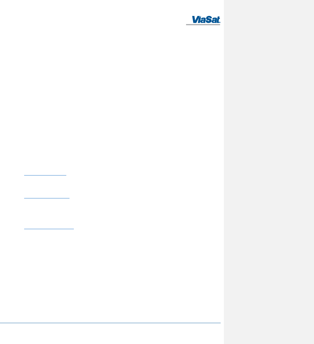
Figure A-1. Cable Assembly Preparation ................................................................................................................................................................................ A-1
Figure A-2. Connector Part Description .................................................................................................................................................................................. A-2
Figure A-3. Cable Assembly - Step 1 ....................................................................................................................................................................................... A-2
Figure A-4. Cable Assembly - Step 2 ....................................................................................................................................................................................... A-2
Figure A-5. Cable Assembly - Step 3 ....................................................................................................................................................................................... A-2
Figure A-6. Cable Assembly - Step 4 ....................................................................................................................................................................................... A-2
Figure A-7. Cable Assembly - Step 5 ....................................................................................................................................................................................... A-3
Figure D-1. Thuraya Satellite Coverage Map .......................................................................................................................................................................... D-1
Figure D-2. LightSquared SkyTerra-1 Satellite Coverage Map ................................................................................................................................................ D-1
List of Tables
Table 1-1. FT2225 Key Specifications ...................................................................................................................................................................................... 1-3
Table 2-1. FT2225 Terminal Connector Pinout ........................................................................................................................................................................ 2-6
Table 3-1. Network Status ....................................................................................................................................................................................................... 3-3
Table 3-2. System Status Fault Codes ...................................................................................................................................................................................... 3-4
Table 5-1. Troubleshooting Guide ........................................................................................................................................................................................... 5-1
Table 5-2. Web MMI Fault Codes ............................................................................................................................................................................................ 5-1
FT2225 Terminal User Manual
1215301, Rev. 001 ViaSat Proprietary Information 1-1
1 INTRODUCTION
1.1 Introduction to ViaSat L-band Managed Service (VMS)
ViaSat IP-based L-band Managed Services meet the need for real-time position tracking, managing remote assets
and operations, and visibility into critical areas of the supply chain. Our high-performance M2M terminals are
designed for a broad range of applications including emergency responders, oil and gas pipeline monitoring, mobile
fleet management, and high-value asset tracking.
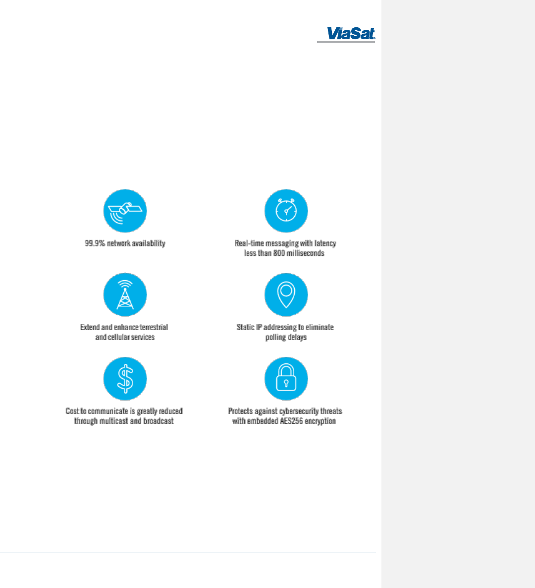
ViaSat’s L-band Managed Services use high-performance LightSquared and Thuraya satellite capacity where one
terminal can be used within either satellite coverage footprint.
In general, VMS offers the following advantages, as shown in Figure 1-1.
Figure 1-1. ViaSat L-band Managed Service (VMS)
FT2225 Terminal User Manual
1215301, Rev. 001 ViaSat Proprietary Information 1-2
1.2 Introduction to the M2M FT2225 Terminal
The ViaSat High Performance FT2225 Terminal is a compact, rugged fixed L-band satellite terminal designed to
provide dependable, instant IP-based machine-to-machine (M2M) communications via ViaSat’s L-band Managed
Service (VMS) (Figure 1-2). The FT2225 two-way networking capability enables both real-time monitoring and real-
time control for a wide range of applications such as:
• Oil and gas mid-stream and down-stream monitoring and control
• Power grid neighborhood area networks
• Water treatment and distribution monitoring and control
• Slope monitoring
• Point-of-sales
• ATM kiosks
• National lottery
• Warning systems
Figure 1-2. FT2225 Terminal
Field devices can instantly be assessed and adjusted remotely; such as gas valves, smart grid sensors, water pumps,
and reservoir level indicators, and data and voice communications. AES-256 data link layer encryption is employed
to ensure the integrity of your data is not compromised.
The terminal includes embedded, beyond-line-of-sight connectivity, enabling direct communications between
remote locations and with control nodes. With an IP-based network architecture and multiple wired and wireless
interfaces, the ViaSat FT2225 terminal easily integrates with your existing M2M system to support any real-time
remote monitoring and control application.
Rugged IP66 dust and powerful water jet resistant enclosure ensures reliable communications in the toughest
environments.
The guidelines below provide an overview of the terminal’s capabilities and basic operation. For detailed
configurations, please contact your ViaSat FT2225 retailer, or the ViaSat customer support hotline listed at the back
of this manual.
1.3 Features of FT2225
Key Features of the ViaSat FT2225 include:
• IP-based networking
• LHCP & RHCP operation
FT2225 Terminal User Manual
1215301, Rev. 001 ViaSat Proprietary Information 1-3
• Wired Ethernet and WiFi interfaces
• Easy antenna pointing via an app on your smartphone or tablet
• Built-in DHCP/NAT router
• Full-duplex connectivity
• Low-latency for instant message transfer and real-time monitoring with no delays
• Embedded commercial GPS + GLONASS
• Netted Voice
• IP66
• 10-32 V DC Input
• Built-in Web MMI
• AES-256 Encryption
1.4 FT2225 Standard Equipment and Optional Accessories
1.4.1 Standard Equipment
The FT2225 features the following standard accessories:
• FT2225 Terminal
• Connector mating kit
• 2x .250-20 UNC-2A screws
1.4.2 Optional Accessories
The following optional accessories are available for FT2225:
• Cable assembly, Power/Ethernet, Pig Tail, 10m - Part # 1212846
• Power/Ethernet Cable – Part # TBD
• Pole Mount Kit – Part # TBD
• Roof Mount Kit – Part # TBD
• Adapter Cable – Part # TBD
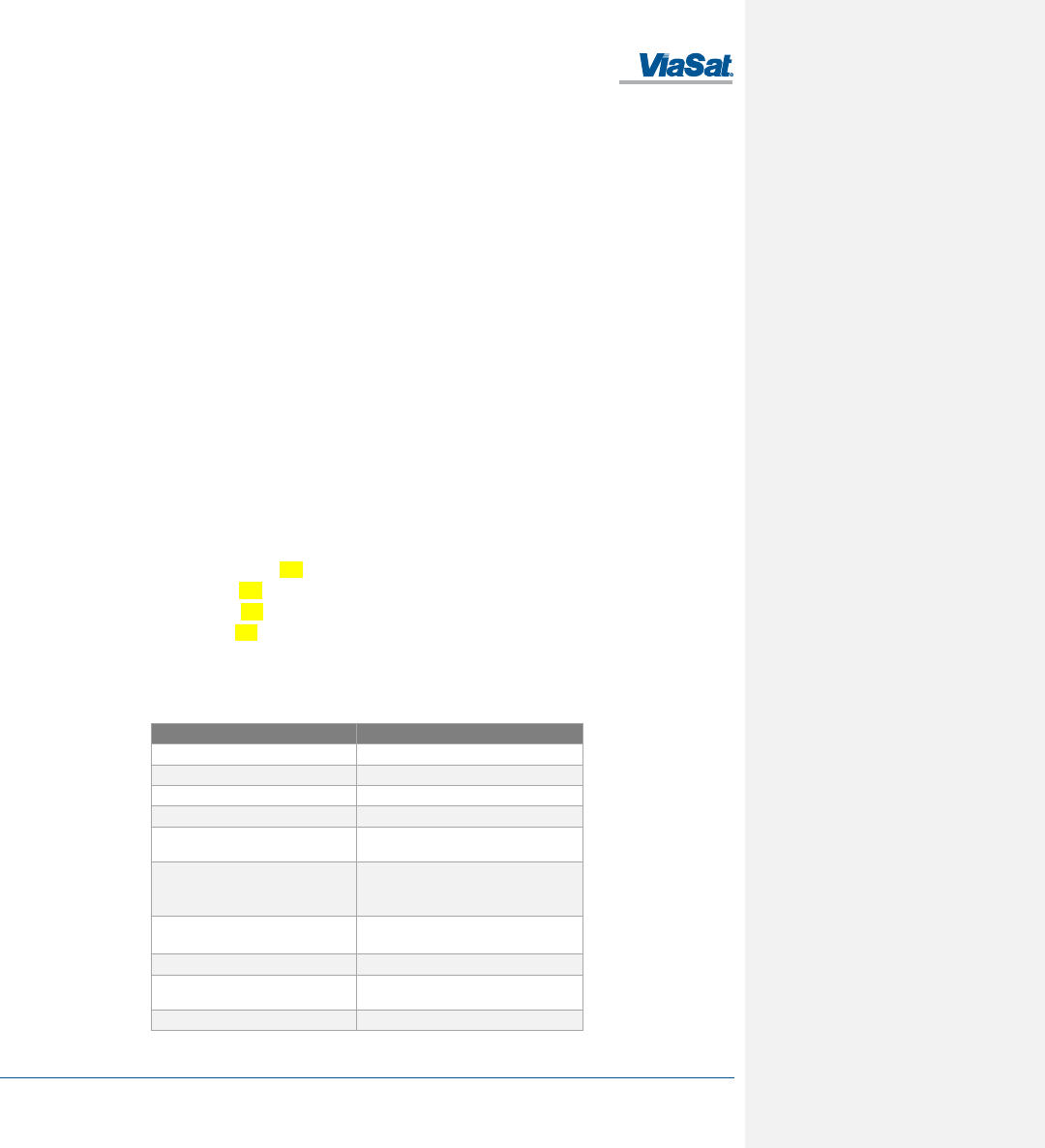
1.5 Key Specifications
The key specifications for ViaSat FT2225 are summarized in Table 1-1 below.
Table 1-1. FT2225 Key Specifications
Category
Specification
Size (LxWxH in.):
7.23” x 5.13” x 1.63”
Weight
< 2.64lbs
Power Consumption
18W max
Antenna Receive G/T
Up to -21.0 dB/K at Zenith
Antenna Transmit EIRP
Up to +4 dBW at Zenith, configurable in 0.1
dB steps
Frequency Range
Extended L-band
RX: 1518.0-1559.0 MHz
TX: 1626.5-1675.0 MHz
Modulation
RX: BPSK, QPSK, 8-PSK and 16-APSK
TX: CRMA
Waterproof/Dustproof
Transceiver: IP 66
Humidity
up to 95% condensing at 45°C, per IEC
60068-2-30
Temperature - Operating
-40°C to +71°C
FT2225 Terminal User Manual
1215301, Rev. 001 ViaSat Proprietary Information 1-4
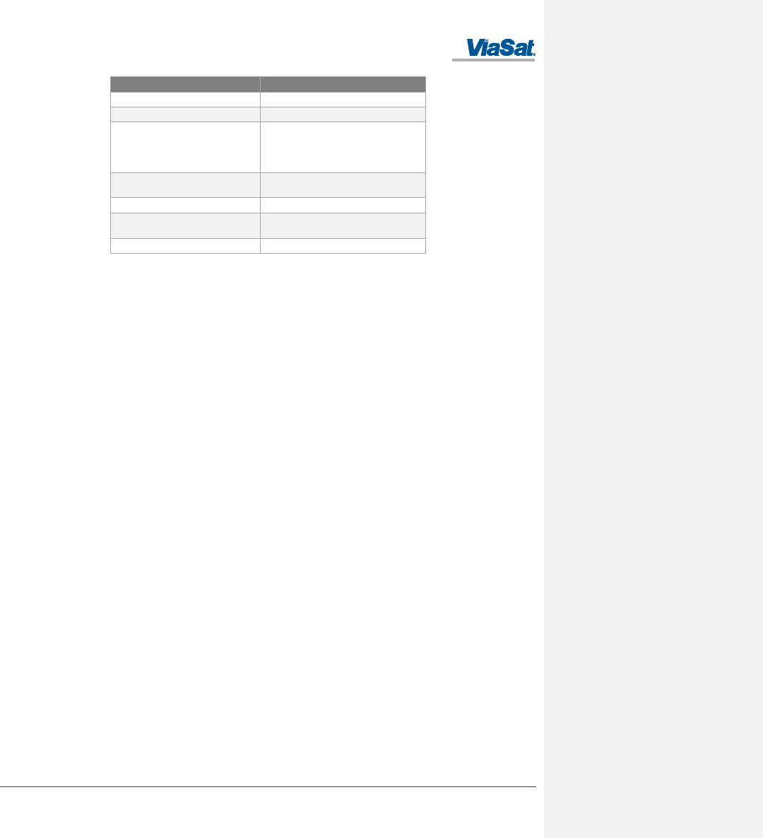
Category
Specification
Temperature - Storage
-40°C to + 85°C
Solar Radiation
1120 W/m2; per IEC-60068-2-5
Vibration (Operational)
Random vibration of 1.05g rms at vibration
spectrum:
5 to 20 Hz: 0.02g2/Hz
20 to 150 Hz: -3dB/octave
Vibration (Survival)
Transportation vibe per IEC 60068-2-64,
Freq: 5-200Hz, ASD: 1.0m2/s3
Shock (Operational)
IEC 60068-2-64, 50m/s2, 11 ms
Shock (Survival)
Transportation shock per IEC 60068-2-29, A
= 180m/s2, t = 6mS
Approval
CE, FCC, IC
FT2225 Terminal User Manual
1215301, Rev. 001 ViaSat Proprietary Information 2-1
2 GETTING STARTED
2.1 Unpacking
The FT2225 is shipped in packaging materials that are uniquely designed for the product. The following packing list
describes the contents of a typical FT2225 shipment:
1. FT2225 Terminal
2. Mating Connector (assembly required)
3. Hardware Kit (2x .250-20 UNC-2A screws)
Upon unpacking of the box, inventory the contents and inspect for sign of damages during shipping. Contact your
retailer in case of missing contents or noticeable defects.
To get started, the additional following items are required:
1. Mount (Platform Dependent)
2. Grounding cable (Platform Dependent)
3. Phillips Screwdriver
4. Compass/inclinometer
NOTE: Contact your terminal integration partner for specific mounting equipment.
2.2 Selecting Mounting Location
The ViaSat FT2225 Terminal is designed for fixed outdoor installation. The terminal can be mounted on a pole or flat
surface using one of the Installation kits (optional accessories).
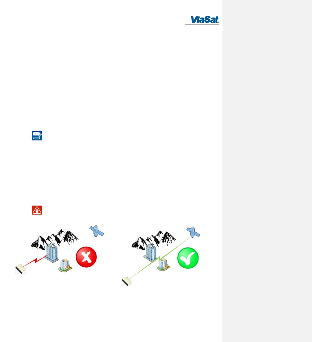
Mounting location should be selected to provide the terminal with a clear line-of-sight to the operational satellite.
Error! Reference source not found. Figure 2-1 illustrates improper vs proper placement of the terminal. On the left,
the terminal is placed in front of a tall building, resulting in an obstructed view of the satellite . On the right, the
terminal is placed away from the taller building and has a clear, unobstructed view of the satellite.
Terminal should be placed as far away from other transmit antennae as possible.
A minimum of 2 ft. from GNSS antennae is recommended.
WARNING: Terminal antenna should be kept at least 1 foot from direct exposure to humans.
Poor location
Good unobstructed location
Figure 2-1. Terminal Location – Line of Sight
FT2225 Terminal User Manual
1215301, Rev. 001 ViaSat Proprietary Information 2-2
2.3 Installation
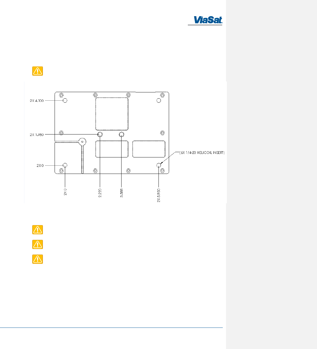
The terminal is 7.23” long by 5.13” wide (excluding connector) and 1.63” high. The terminal is designed to be hard-
mounted to fixed platforms. Two .250-20 UNC-2A size mounting hole locations are located on the underside of the
terminal as shown in Figure 2-2. Optimal mounting method depends on chosen location. Examples of mounting
methods are illustrated in Figure 2-3.
CAUTION: The “Caution” icon identifies procedures or factors that can affect the installation
and configuration of the system (may damage or render equipment inoperable).
Figure 2-2. Terminal Mounting Hole Locations
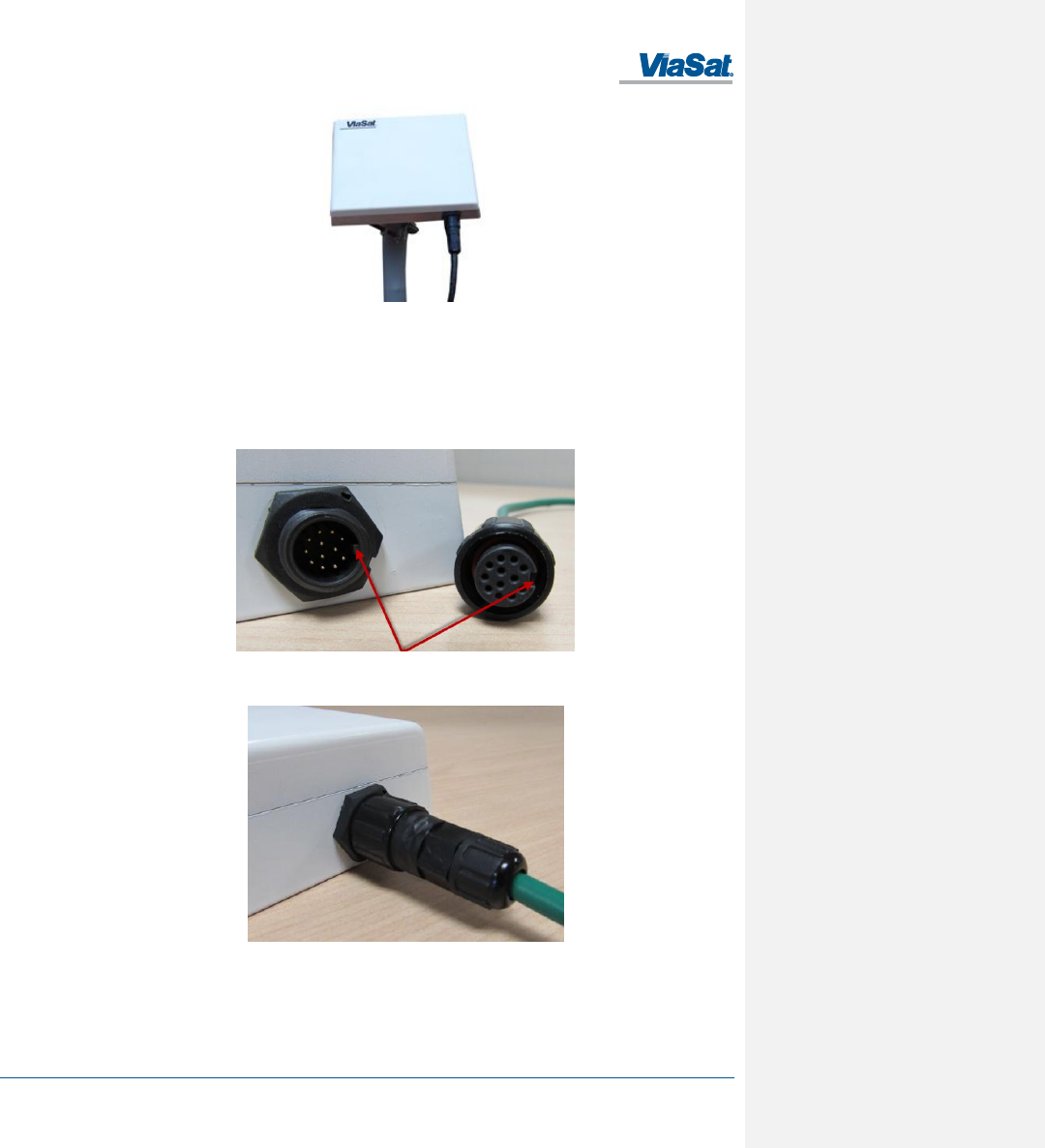
The terminal should be installed with the connector facing down or sideways, but not up. An example of installation
with connector facing down is shown in Figure 2-3.
CAUTION: Do not over tighten.
CAUTION: Do not apply pressure to the cable/connector during the installation.
CAUTION: Do not force the connector pins to mate since this may damage the pins.
Note: Contact your
terminal integration
partner for specific
mounting equipment.
FT2225 Terminal User Manual
1215301, Rev. 001 ViaSat Proprietary Information 2-3
Figure 2-3. Terminal Mounting Example
A minimum of 4.00 inches of clearance from the connector side of the terminal is suggested for cable access and
strain relief.
Reattach the connector to the terminal receptacle carefully. Align the plug tab with the receptacle tab as shown in
Figure 2-4 and gently push the connector until it stops. Rotate the locking collar on the connector gently until it is
properly engaged as shown in Figure 2-5. AVOID USING A WRENCH OR PLIERS TO TIGHTEN OR LOOSEN THE
CONNECTOR. Using a tool other than your hand may result in over-torqueing or damaging the internal seals.
Figure 2-4. Key Slot
Figure 2-5. Cable Connector and Locking Collar
Install adhesive-lined shrink tubing as required around the cable ends to improve cable harness performance and
maximize wear life.
Install a metal cable tie holder with an outdoor rated epoxy/adhesive for best holder retention.
FT2225 Terminal User Manual
1215301, Rev. 001 ViaSat Proprietary Information 2-4
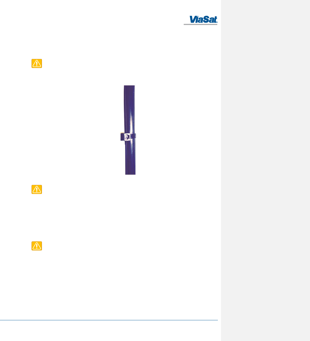
Secure the cable with metal tie holders and black UV-rated cable ties at intervals along the cable assembly to
minimize cable and connector strain as shown in Figure 2-6.
Leave enough slack at the terminal connector end to reduce tension when installing or removing the connector.
Route the remaining cable assembly neatly for a professional installation appearance.
CAUTION: Cable management and connector strain relief must be incorporated in the
installation. Securing the cable at regular intervals along its length as part of the installation to
prevent cable wear and eliminate strain on the terminal connector. Damage to the terminal
connector interface or cable may otherwise result leading to hardware failure.
Figure 2-6. Cable Management
CAUTION: Turn off Power Supply before connecting to terminal.
After mounting the terminal to a support and reattaching the connector to the terminal, it is ready for power on.
2.4 Powering Up
The FT2225 terminal is designed to automatically start up when DC power is applied. An ON/OFF power switch does
not exist on the terminal.
At the completion of its power-up sequence, the terminal will automatically search for GNSS and VMS satellite
signals.
CAUTION: Do not stand in front on the unit once power is applied.
2.5 Obtaining a GNSS Fix
The VMS network does not require the terminal location to access the network. However, terminal location enables
optimal customer service.
At the completion of its power-up sequence, the terminal will automatically search for GNSS and VMS satellite
signals. The default position reporting uses GPS satellites and the terminal will automatically attempt to get a new
GPS lock every time it is powered on. Obtaining a lock may take up to 5 minutes upon power-up.
FT2225 Terminal User Manual
1215301, Rev. 001 ViaSat Proprietary Information 2-5
2.6 Antenna Pointing
In order to obtain the best possible signal, it is important that the terminal is pointed correctly towards a VMS
satellite. Incorrect pointing may result in poor signal quality, and in some cases prevent the terminal from being able
to operate on the VMS network.
2.6.1 Pointing Using Commercial Satellite Finder Apps
Appendix F: VMS Pointing Procedure contains a list of popular antenna pointing apps. Use Coverage map provided
in Appendix E: Satellite Coverage Map to determine appropriate VMS satellite.
Follow direction in Appendix F: VMS Pointing Procedure to point the terminal.
CAUTION: Do not touch the radome when pointing the antenna in order to avoid blocking the
signal.
2.6.2 Pointing Using Web Server
Select Antenna Pointing under the Administration tab. The RSSI meter reports a value that is proportional to
receiver signal strength. Turn and tilt the antenna to fine tune pointing using the signal strength indicators. The
number of bars that are green indicates the strength of the received signal. Try to maximize the number of bars..
2.6.3 Pointing Using VMSFinder
CAUTION: Disconnect the power cable before performing the pointing procedure using
VMSFinder.
VMSFinder is an antenna pointing application, developed specifically for VMS. In order to use VMSFinder with your
smart phone, you will first need to download and install VMSFinder from TBD. Please ensure that power is
disconnected from the FT2225.
To perform pointing procedure, perform the following actions:
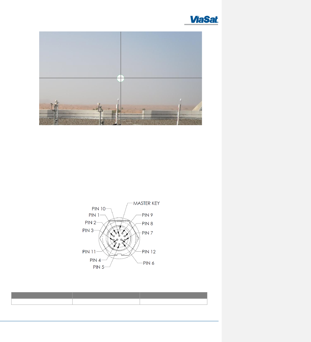
1. Start Sat Aligner app.
2. Make sure that location services is enable on your smart phone (VMSFinder uses GPS position to select the
proper satellite).
3. Lay the phone flat on top of the FT2225 radome.
4. Turn and tilt the FT2225 and the phone together until the circle representing the satellite moves to the center
crosshairs and turn green.
5. Secure the unit in place.
6. The FT2225 is now ready for use.
FT2225 Terminal User Manual
1215301, Rev. 001 ViaSat Proprietary Information 2-6
Figure 2-7. VMSFinder Pointing Application
2.7 Connecting the FT2225 to Other Equipment
2.7.1 Interfaces
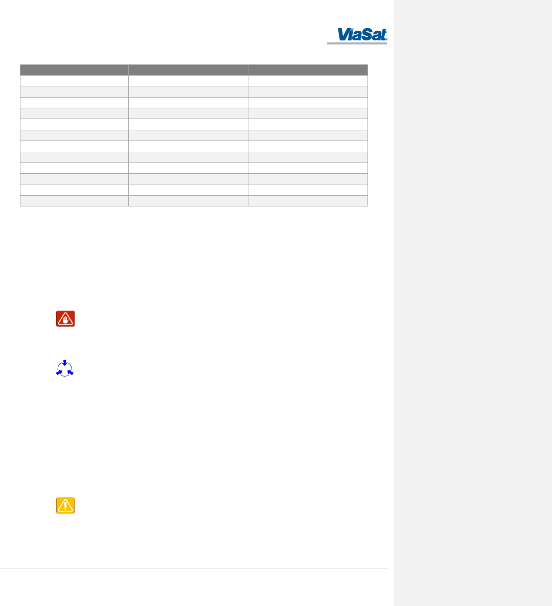
The FT2225 Terminal offers the following wired interfaces via a multi-pin circular connector as shown in Figure 2-8
and Table 2-1.
• DC Power
• LAN
The FT2225 Terminal offers the following wireless interfaces:
• WLAN
Figure 2-8. View of FT2225 Terminal Receptacle
Table 2-1. FT2225 Terminal Connector Pinout
Manufacturer
Receptacle Part Number
Mating Connector Part Number
CHOGORI
22012515-02
22012211-01
Thuraya-2
El: 57.9o
Az: 205.1o
El: 58.0o
Az: 205.2o
FT2225 Terminal User Manual
1215301, Rev. 001 ViaSat Proprietary Information 2-7
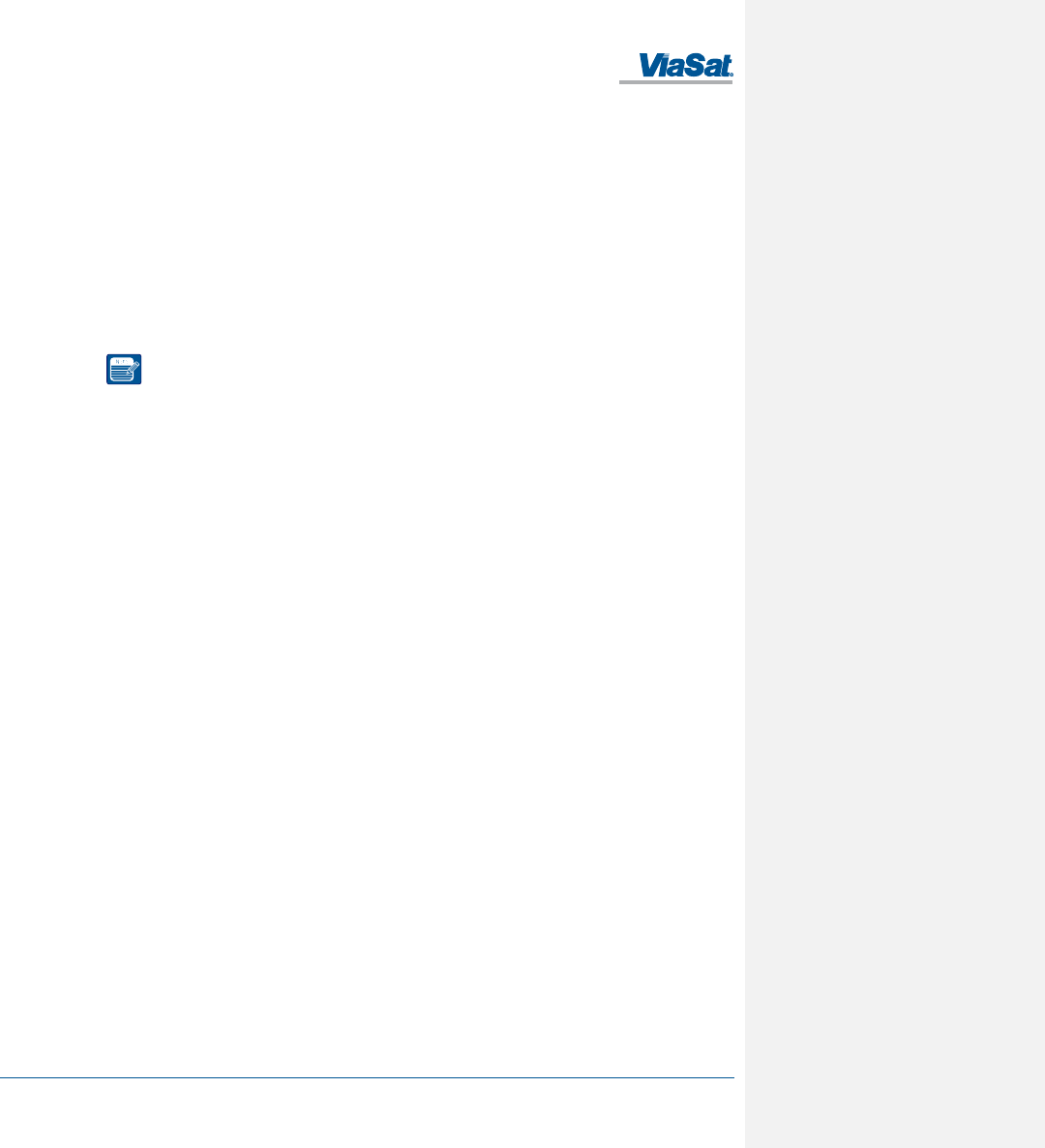
Pin Number
Signal Name
Description
1
RX-
ETHERNET RX (-)
2
RX+
ETHERNET RX (+)
3
TX-
ETHERNET TX (-)
4
TX+
ETHERNET TX (+)
5
NC
NO CONNECT
6
VIN RTN
VDC RETURN
7
VIN RTN
VDC RETURN
8
VIN
+10VDC to +32VDC
9
VIN
+10VDC to +32VDC
10
Reserved
Reserved
11
Reserved
Reserved
12
Reserved
Reserved
2.7.2 Wired Interface
2.7.2.1 DC Power Interface
The FT2225 Terminal is designed to use +10 to +32 Volt Direct Current (VDC) electrical power systems. Optimal
power supply efficiency is when input supply voltage is closer to the lower end of the range. ViaSat recommends
using a 12V power supply when possible.
The nominal power consumption when receiving is approximately 7 Watts (W). During transmission bursts or
terminal boot up, the power draw can be up to 18W with a 4.5A surge for 5 milliseconds. ViaSat recommends a
power supply with a minimum power rating of 25W to provide adequate power margin as well as to support the
initial turn-on current surge of 4.5A.
WARNING: Observe proper grounding. Failure to ground the terminal may result in severe
personal injury or death.
Do not apply an input voltage to the terminal outside of the specified range. This will
permanently damage your terminal.
CAUTION: Observe proper Electro-static Discharge (ESD) practices during installation.
The terminal protects against continuous inputs of -32.0 VDC to +32.0 VDC. Applying an input voltage outside this
range may permanently damage the terminal and cause it to become non-operational.
The terminal offers a bonding point by using .190-32 UNF 2B threaded, blind hole. This bonding point allows the use
of a threaded fastener to connect the terminal to platform potential.
The FT2225 will automatically start up when DC power is applied. There is no ON/OFF power switch.
2.7.2.2 Ethernet Interface
The Ethernet interface is defined by IEEE 802.3 for operation in 10Base-T and 100Base-TX modes with the exception
of the connector type. Cabling for Ethernet connectivity must meet ANSI/TIA/EIA-568-A specifications for Category
5 or Category 5e cables. It is recommended that the wired Ethernet interface be used for permanent installation.
Contact your terminal retailer for power/Ethernet cable or build your own cable assembly as shown in section 6.
CAUTION: Use a maximum Ethernet cable length no greater than 100m (328 ft) to ensure
proper terminal operation.
FT2225 Terminal User Manual
1215301, Rev. 001 ViaSat Proprietary Information 2-8
2.7.3 Wireless Interface
2.7.3.1 WLAN Interface
To connect your WLAN-enabled- device to the FT2225, perform the followings:
1. Make sure that WLAN feature on your device is turned on.
2. Place the device near the terminal.
3. Search for available WLAN networks on your device.
4. The default SSID will be vmt_<FTI> where <FTI> should be replaced with the fixed terminal identifier unique to
your terminal. Check the label on the terminal enclosure to obtain the FTI.
5. Select the SSID of your terminal network when it appears on the list.
6. The default password is terminal.
NOTE: Default password of your FT2225 WLAN is terminal.
Encryption type is WPA2
7. It may take up to 2 minutes before a wireless connection is made and the configuration webpage is available.
FT2225 Terminal User Manual
1215301, Rev. 001 ViaSat Proprietary Information 3-1
3 CONNECTING TO THE VIASAT FT2225 TERMINAL
The ViaSat Terminal will attempt to log in automatically to an available satellite network as soon as it is powered on.
Features of the terminal can be controlled using the web interface. The user interface is presented as a web page
that is accessible from the terminal. This interface is used for determining terminal operational status, satellite link
status and other terminal information. This interface allows the user to perform control actions on the terminal for
certain activities such as reboot, managing IP addresses/ports, and controlling default transmit power -up states.
NOTE: The webpage is only available through a local wired Ethernet or WLAN connection to
the terminal. This interface is not accessible through the satellite network and will not transmit
data over the satellite network.
3.1 Web Server Connection
3.1.1 Address/Port Number
The web server address will be the same as the terminal IP Address. By default, the terminal IP Addresses are:
Wired Ethernet interface: 192.168.100.1
WiFi interface: 192.168.200.1
The terminal IP Addresses are defined as the Destination IP Address for incoming datagrams to the terminal. These
addresses are configurable through the configuration web page. The web server port number is set to the standard
port 80.
To connect to the terminal, enable DHCP settings on your PC, and enter the terminal IP address in your web
browser.
If you do not wish to use the default DHCP server configuration, you will need to ensure that your PC’s static IP
address is on the same network as the terminal.
NOTE: The terminal will come from the factory with default DHCP server settings to allow easy
connection.
3.1.2 Protocol
The web server will use the HTTP protocol for connection with the platform interface devices.
3.1.3 Web Browsers Supported
The FT2225 Terminal may be accessed by using the latest released version of the Google Chrome™ browser.
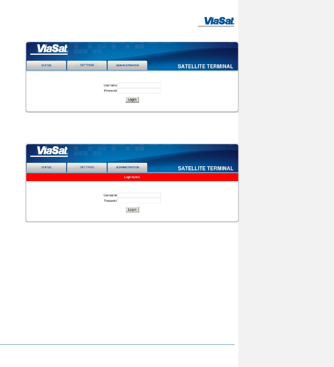
3.2 Login
The web server will present a login screen for the user to access all activities shown below. Without the proper user
login, no terminal functionality or status is available from the web page. The terminal will be responsive to all login
requests during all modes of operation.
Contact your terminal retailer or integrator for login credentials for your ViaSat FT2225 Terminal.
FT2225 Terminal User Manual
1215301, Rev. 001 ViaSat Proprietary Information 3-2
Figure 3-1. Login Screen
The default Username/Password is admin/admin. After a successful login, the user will be directed to the System
Status page in Section 3.
After an unsuccessful login, the following web page with error banner is presented.
Figure 3-2. Failed Login
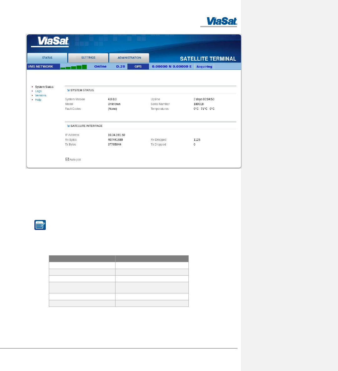
3.3 Status Tab
The status bar is included at the top of each page. It displays the current status of the connection to the network
and the latest GPS information (Figure 3-3).
FT2225 Terminal User Manual
1215301, Rev. 001 ViaSat Proprietary Information 3-3
Figure 3-3. Status Tab
3.3.1 Network
The received signal strength bars indicate the current received signal strength. The number of bars that are green
indicates the strength of the received signal for the modulation scheme being used on the current received forward
link. The more bars there are the stronger the signal.
The status field shows the current state of the terminal on the network. Possible statuses are shown below in Table
3-1:
NOTE: Signal strength will vary based on factors such as terminal location, current data rate,
and service plan.
The GNSS fields show the current location. The location will only be valid when the terminal has acquired enough
GPS/GLONASS satellites for a valid fix.
Table 3-1. Network Status
Status Field
Status Meaning
Searching
Terminal is searching for the forward link
Acquired
Terminal has acquired a forward link
Registering
Terminal is registering with the network
Online
Terminal logged in to the network and ready
for use
Offline
Terminal logged off the network
Re-Registering
Terminal requesting to re-login
3.3.2 GNSS
The GNSS fields show the current location. The location will only be valid when the terminal has acquired enough
GPS/GLONASS satellites for a valid lock.
FT2225 Terminal User Manual
1215301, Rev. 001 ViaSat Proprietary Information 3-4
3.3.3 System Status
System status displays general information about the current system (Table 3-2).
The Tx Bytes and Rx Bytes fields display the number of bytes sent and received over the satellite. The Tx Dropped
field displays the number of outgoing packets intended to be sent over the satellite link but were dropped due to
queue limitations, encryption failure or other transmit errors. The Rx Dropped field displays the number of incoming
packets that were dropped due to space limitations, decryption failure, data integrity check failure or other
reception errors.
The Temperature field displays current temperature in Celsius within the terminal.
CAUTION: If you are experiencing issues with your ViaSat FT2225 Terminal or observing fault
codes after reboot attempts, contact customer support.
Table 3-2. System Status Fault Codes
Description
Fault Code
Action
General fault
0x01 - 0x53
Reboot the terminal.
Overtemp fault
0x61 - 0x63
Place terminal in environment less than +70°C and power
off until terminal cools down.
Undertemp fault
0x69 -0x6B
Place terminal in environment greater than -40°C until
terminal warms up.
Power fault
0x70 or other
Reboot the terminal.
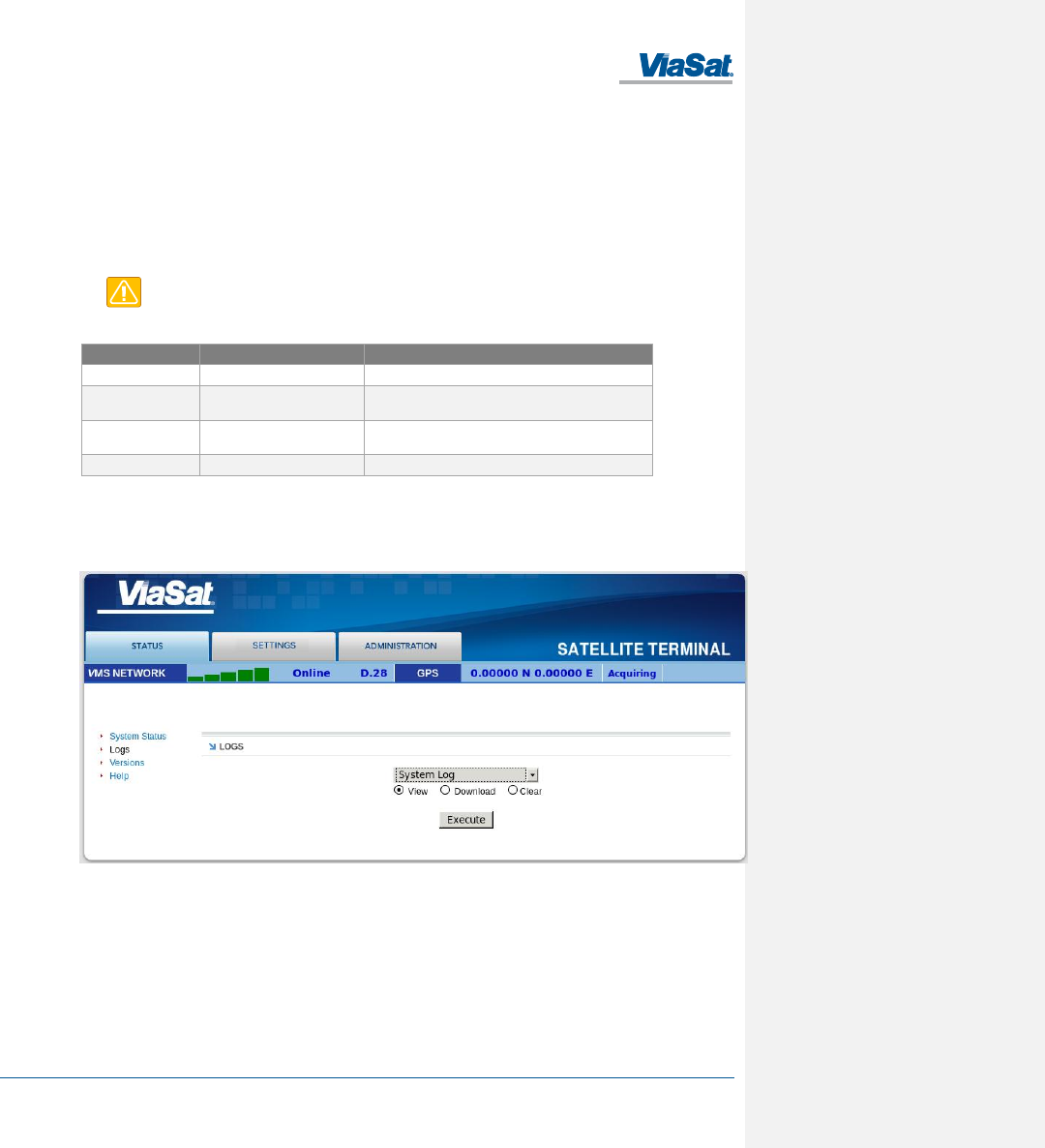
3.3.4 Logs
The Logs page allows the user to view or display system log files. All log files with the exception of the NV (Non-
Volatile) Log are volatile are not maintained through reboots. The NV Log contains high priority information that is
saved through reboots (Figure 3-4).
Figure 3-4. Logs Pane
System Log
The System Log displays information about the operating system environment, including drivers and devices.
Control Message Manager
The Control Message Manager processes network control messages and maintains the terminal login state.
Web Administration
This log file contains information about actions performed by or when using the Web Administration interface.
FT2225 Terminal User Manual
1215301, Rev. 001 ViaSat Proprietary Information 3-5
AT Server
The AT Server logs interactions between the internal AT command server and external AT clients.
GPS
The GPS provides information regarding the internal GPS receiver and client.
NV Log
The NV logs high-priority terminal information that is maintained through reboots.
3.3.5 Versions
This field displays the version number of each terminal software component.
3.4 Settings Tab
The settings tab lists terminal settings that can be modified by the user. A description of each setting is listed below.
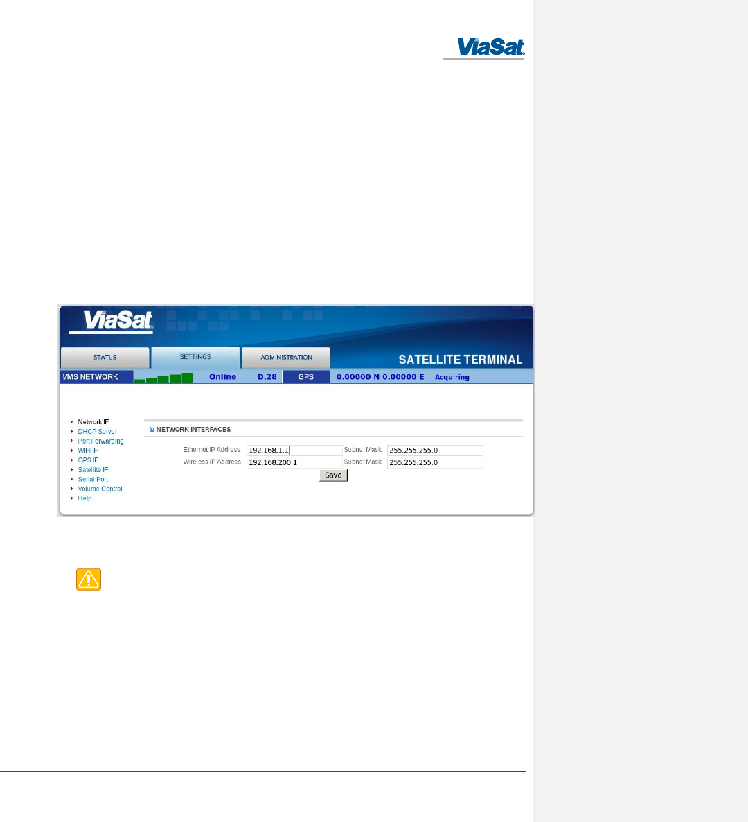
3.4.1 Network IF
The Network IF pane allows the user to set both the wired and wireless IP/subnet mask for the terminal (Figure 3-5).
Figure 3-5. Network IF Pane
Configure the Ethernet interface IP Address and Subnet Mask. These fields must be in dot notation (a.b.c.d) and
contain a valid IP address.
CAUTION: Modifying the IP Address and Subnet Masks can result in loss of connectivity to the
terminal. See Section 4 for more information on network configuration settings and examples.
3.4.2 DHCP Server
There are two options for DHCP server configuration: dynamic and static (Figure 3-6).
Dynamic Assignments
The DHCP server can be configured with a pool of IP addresses that it will lease to clients.
The Pool Start and Pool End fields are set to the start and end IP addresses. The Netmask field is set to the subnet
mask that a client should use. Each of these fields must be a valid IP address or subnet mask in dot notation
(a.b.c.d).
The lease time is the time in minutes that a lease given to a client will be valid.
FT2225 Terminal User Manual
1215301, Rev. 001 ViaSat Proprietary Information 3-6
Static Assignments
The DHCP server can also be configured to provide a static IP address to a particular network device. The network
device is determined by its hardware MAC address. Each time the DHCP server gets a request from a device that
matches the MAC address the assigned IP address will be given to the device.
The Name field is the hostname of the network device that will be assigned a static IP address. This name must not
contain any white space and should consist of alphanumeric characters, hyphens or underscores. The MAC Address
field is set to the MAC address of the network device. This field must be specified as follows: xx:xx:xx:xx:xx:xx, where
xx is a two-digit hexadecimal number. The IP Address field specifies the IP address to be assigned to the network
device with the corresponding MAC address. The IP address is specified in dot notation (a.b.c.d).
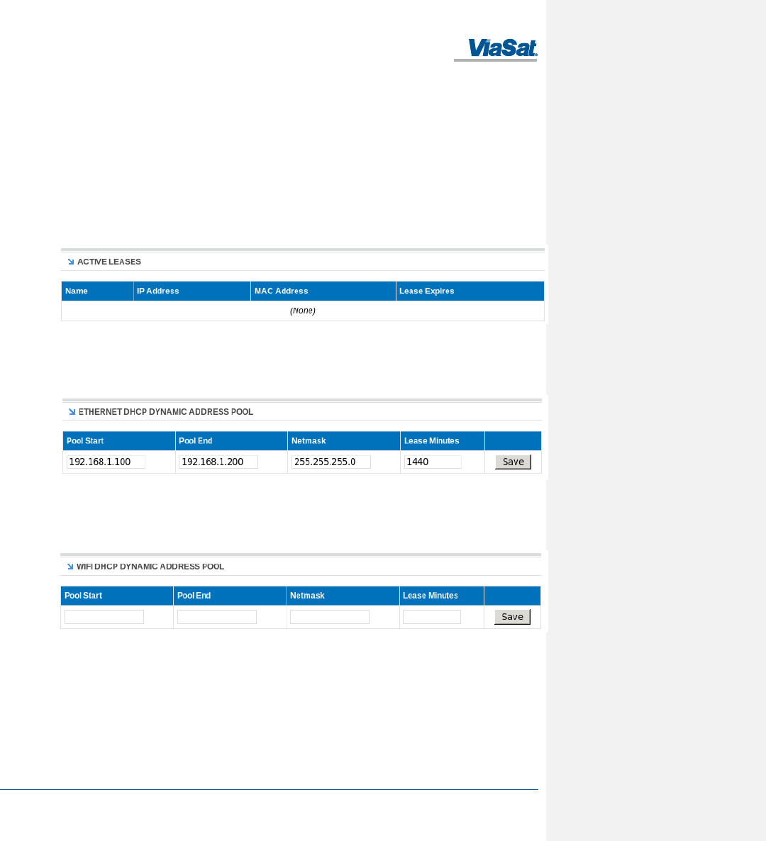
Active Leases Table
Any currently active DHCP assignments are shown in the Active Leases and Static IP Assignments in Figure 3-6.
Figure 3-6. DHCP Server - Active Leases
Ethernet DHCP Dynamic Address Pool
The IP address allocation and lease time for the wired Ethernet dynamically-assigned DHCP address pool is
configured in Figure 3-7.
Figure 3-7. DHCP Server - Wired Ethernet DHCP Dynamic Address Pool
WIFI DHCP Dynamic Address Pool
The IP address allocation and lease time for the WLAN dynamically-assigned DHCP address pool is configured in
Figure 3-8.
Figure 3-8. DHCP Server - WLAN DHCP Dynamic Address Pool
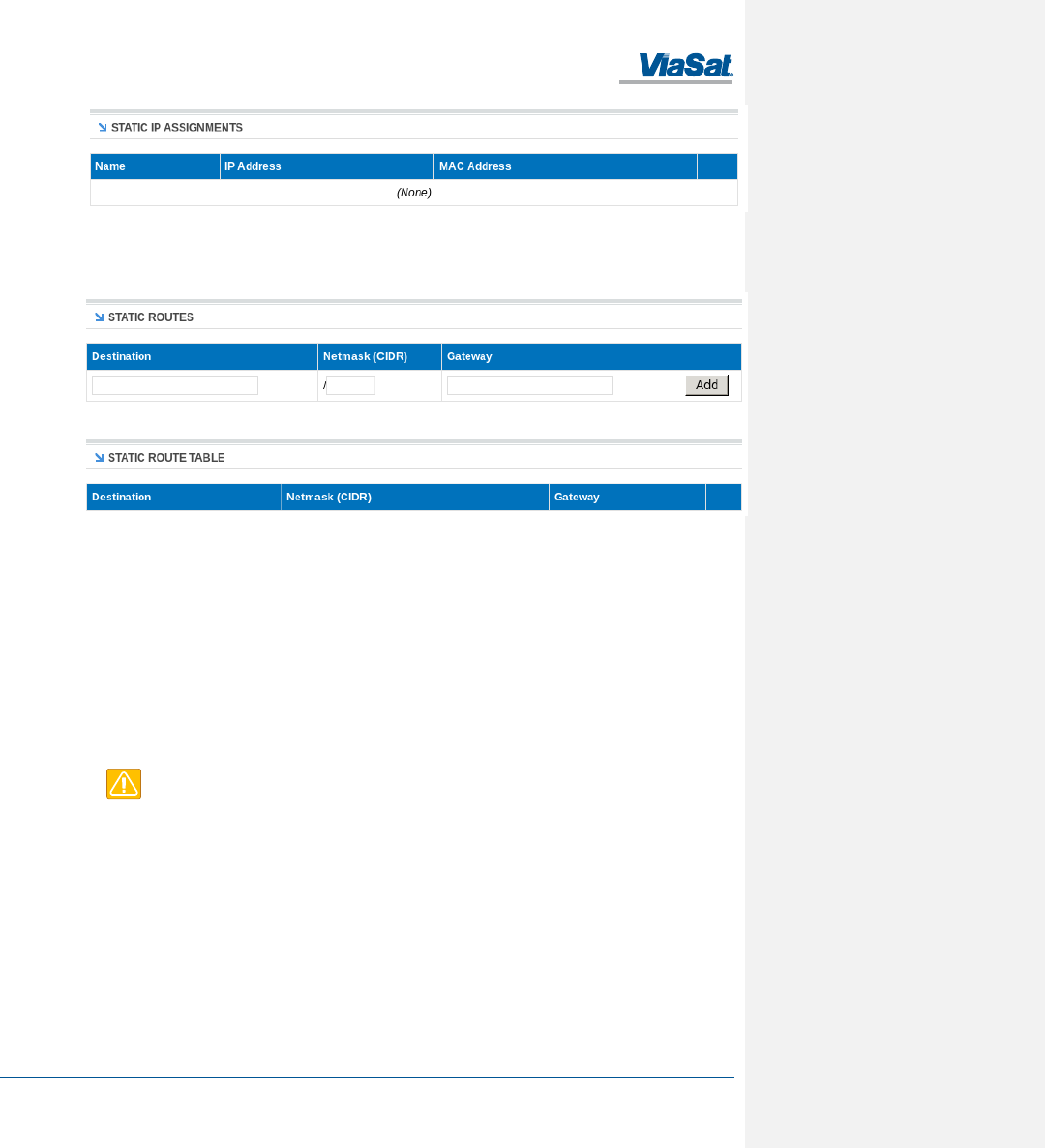
Static IP Assignments
The IP address to MAC pairing for static IP assignments is contained in Figure 3-9.
FT2225 Terminal User Manual
1215301, Rev. 001 ViaSat Proprietary Information 3-7
Figure 3-9. DHCP Server - Static IP Assignments Table
Static Routes
Static routes are configured and listed in Figure 3-10
Figure 3-10. DHCP Server - Static Routes Tables
3.4.3 Port Forwarding
The ViaSat terminal provides a network address translator (NAT) that creates a private network for devices attached
to the terminal. Devices behind the terminal NAT are invisible to any hosts outside the terminal NAT.
The only way to access a device behind the terminal is either:
• Have the device behind the terminal initiate the connection
• Create a port forwarding assignment to the device in the terminal
Port forwarding allows incoming UDP or TCP packets destined for a specific port to be forwarded to a network
device (client or host) “behind” the terminal NAT. The incoming packet will be forwarded to the destination port and
IP address defined by the port forwarding rule. Using port forwarding assigns the port being forwarded to a single
host IP address and excludes this port from being used by any other host.
CAUTION: Modifying port forwarding settings can result in loss of connectivity to the network.
See Section 4 for details on network configuration and examples.
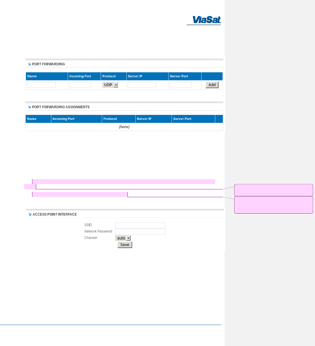
Port Forward Assignments
Any currently active port forwarding assignments will be shown in the Port Forwarding Assignments table (Figure
3-11).
To add a port forwarding configuration, enter the following information into the Port Forwarding table:
1. Name – Set to the logical name of the service being forwarded. This name must not contain any white space
and should consist of alphanumeric characters, hyphens or underscores.
2. Incoming Port – Set to the port number of the service to be forwarded, such as 21 for FTP.
3. Protocol – Select between UDP/TCP/Both.
4. Server IP – Set to the IP address, in dot notation, of the host that the packets will be forwarded to.
FT2225 Terminal User Manual
1215301, Rev. 001 ViaSat Proprietary Information 3-8
5. Server Port – Set to the port number on the Server IP that the packets will be sent to. This port can be the
same as the Incoming Port, but does not need to be.
6. When complete, click Add and the assignment will show up in the Port Forwarding Assignments shown in
Figure 3-11 .
Figure 3-11. Port Forwarding Pane
3.4.4 WIFI IF
The WIFI IF pane is used to configure your wireless access point interface for the WLAN (Figure 3-12).
To configure the access point settings set the following:
1. SSID – This is also known as your network name. Provide a unique SSID for the network. The name must not
exceed 32 keyboard characters.
2. Network Password – The terminal uses WPA2 encryption. Use this field to set the network password for the
WLAN.
3. Channel – Choose the operating channel for your WLAN.
4. Click Save.
Figure 3-12. WIFI IF Pane
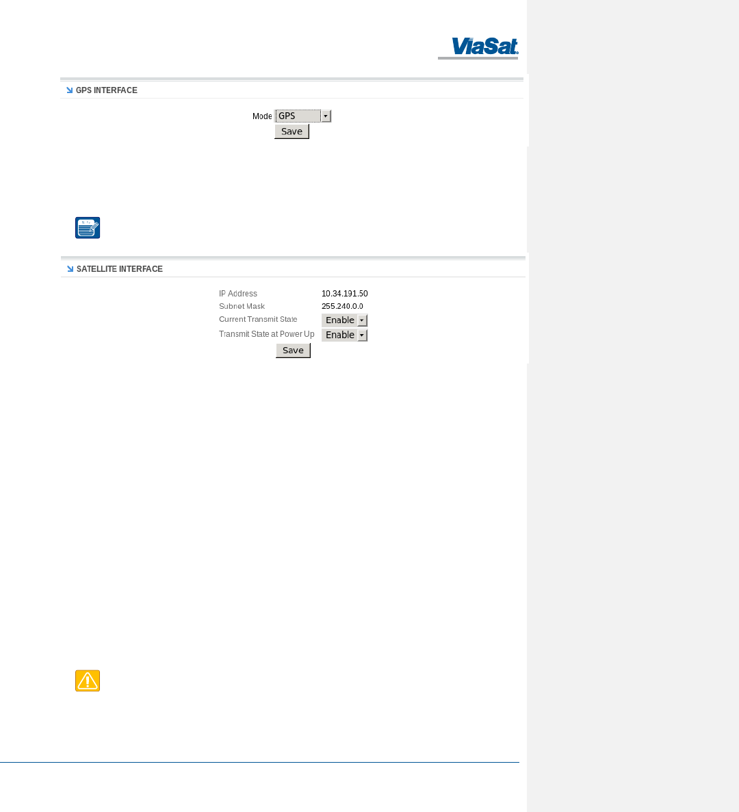
3.4.5 GPS/GLONASS IF
The GPS/GLONASS IF pane is used to select the operating mode for the GPS/GLONASS location services (Figure
3-13).
Select the pull-down for the desired mode and click Save.
Comment [DC1]: Confirm with Kyle
Smith
Comment [DC2]: The last time I saw this
sw, this was not a user configurable
setting. Confirm with Kyle Smith
FT2225 Terminal User Manual
1215301, Rev. 001 ViaSat Proprietary Information 3-9
Figure 3-13. GPS/GLONASS IF Pane
3.4.6 Satellite IF
Configure the satellite interface transmit settings. These settings can be used to inhibit terminal transmissions, both
in real-time and at boot up (Figure 3-14).
NOTE: If terminal transmit is inhibited at boot up it will not be able to communicate on the
VMS network until transmit is enabled.
Figure 3-14. Satellite IF Pane
The IP Address and Subnet Mask fields contain the external (Satellite Interface) address configuration assigned to
your terminal. These fields are assigned by your service provider.
Current Transmit State – Allows you to disable your terminals ability to transmit.. For normal operation, this should
be set to Enabled. If disabled, your terminal will not be able to send data over the satellite interface.
Transmit State at Power Up – Allows you to alter the power up behavior so that the terminal will not transmit when
powered up. For normal operation, this should be set to Enabled. If disabled, your terminal will not be able to send
data over the satellite interface upon power up.
3.5 Administration Tab
The Administration tab provides additional information and settings such as file uploads and user administration.
Antenna Pointing
This field applies to the ViaSat FT2225 Terminal only. To achieve optimum satellite link performance and stability,
the terminal should be pointed directly towards the satellite. Section 2.6 contains details on how to optimally point
the terminal. This pane reports the current receive signal strength indication (RSSI) of the terminals satellite
network link.
Crypto
Displays status of the encryption engine used to provide data security.
File Upload
The file upload function is used to upload terminal configuration files.
CAUTION: Improper file uploads can cause severe damage to the terminal. File uploads should
only be attempted if directed by customer or integrator support.
HW Diagnostics
FT2225 Terminal User Manual
1215301, Rev. 001 ViaSat Proprietary Information 3-10
Hardware diagnostics executes any or all of the terminal built-in tests. These diagnostics test the basic functionality
of the hardware components of the terminal. They can aid in finding the cause of any hardware faults reported by
the terminal. These tests should only be run when the terminal is offline.
Logout
Initiates log out from the current webpage session.
Net Diagnostics
Network diagnostics initiates pings to the destination IP address up to a maximum count of 10 times. The results of
the pings will be displayed.
OSD Status
Over-the-Air Software Download (OSD) downloads new software into the terminal using the satellite link instead of
a local file upload. This page displays the current status of any downloads in progress. OSD is a "trickle file
download", using only idle capacity in the satellite link sent in the background of transporting of user data.
Passwords
Changes the password of the current logged in user.
TBD How to reset password
Reboot
Initiates reboot of the terminal.
FT2225 Terminal User Manual
1215301, Rev. 001 ViaSat Proprietary Information 4-1
4 IP DATA INTERFACE
The following section details the ViaSat Network architecture, and provides instructions for setting up typical
configurations on the ViaSat Network to use as a reference.
4.1 IP Network Architecture
The IP network architecture and the IP address scheme that network devices communicating through the ViaSat
Hub, with network devices (clients or hosts) “behind” terminals in the ViaSat network must use, is outlined in Figure
4-1, below.
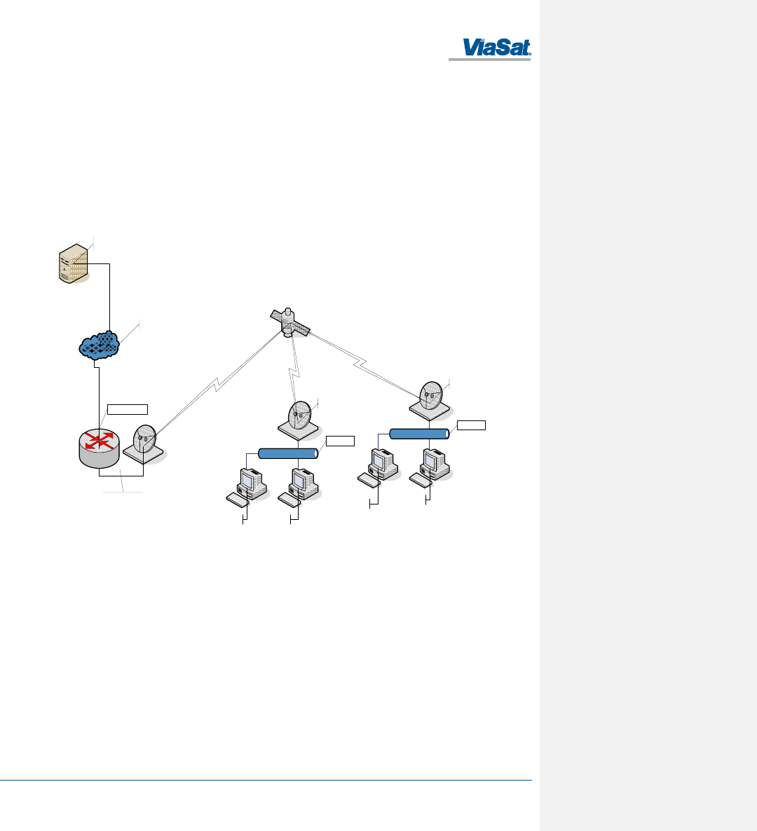
The following illustration shows an example network. An application server connects to the ViaSat Hub through the
Internet to communicate with two terminals, where each terminal has two clients behind it.
Figure 4-1. ViaSat Network Architecture
The IP network architecture uses two NAT devices between an external device connecting via the Internet and
network devices behind the terminal. One NAT exists at the gateway to the ViaSat Hub and another at the terminal.
The terminal NAT provides security to the network behind the terminal by blocking access to devices within the
terminal network from the Internet and devices connected to the ViaSat Hub. Port forwarding in the terminal must
be configured to allow access through the terminal NAT for applications to communicate with devices within the
terminal network.
Any device within the terminal network must also be configured to use the terminal as its default gateway to the
Internet and any devices connected to the ViaSat Hub. This may be accomplished by using the DHCP server in the
terminal or by configuring a default gateway manually on each device within the terminal network.
In order to connect a PC or other device over the ViaSat Network through the terminal, you must properly configure
your device and terminal. The instructions below are for a typical configuration to establish connectivity. Your
terminal retailer or integrator may give you specific instructions to establish a custom network connection in lieu of
the instructions below.
Terminal A Network
``
Terminal B Network
``
Internet
Application
Server
ViaSat Hub
Terminal A
Terminal B
PC A1 PC A2
PC B1 PC B2
NAT/DHCP
NAT/DHCP
VIaSat Hub NAT
FT2225 Terminal User Manual
1215301, Rev. 001 ViaSat Proprietary Information 4-2
For a typical configuration, follow these steps:
1. Determine the applications that will be communicating with devices attached to the terminal via the
terminal LAN/WLAN.
2. For each application determine the protocol used (UDP or TCP) and the port numbers that these
applications will be using.
3. Set your device’s IP settings to use DHCP.
4. Plug your device into the terminal Ethernet cable. The terminal will by default assign a unique IP
address to your device.
5. Login to the terminal webpage interface. See Section 3.2. Select the Settings tab.
6. Select the Port Forwarding option.
7. Enter the Port Forwarding information which includes:
a. Application Port
b. Protocol
c. IP Address of the device these packets will be forwarded to.
d. Port number these packets will be forwarded to. This will typically be the same as the
Application Port.
8. Press Add.
9. Perform steps 7-8 for each application port that needs to be forwarded.
FT2225 Terminal User Manual
1215301, Rev. 001 ViaSat Proprietary Information 5-1
5 TROUBLESHOOTING, MAINTENANCE, AND TECHNICAL SUPPORT
The FT2225 is designed to be very reliable andrugged. The terminal performs automated self-tests and also provides
for alarms, manual self-tests, and system resetting to further evaluate the cause for, and possibly correct, any
unexpected functionality. A further list of problems that might arise, their possible causes, and potential remedies is
provided in Section 5.1.
TODO List available self tests
5.1 Troubleshooting Guide
Faults may be detected by visual observation or by built-in test (BIT). Problems uncovered during preventive
maintenance, or while the terminal is in service, their possible cause, and recommended corrective action(s) are
described in Table 5-1.
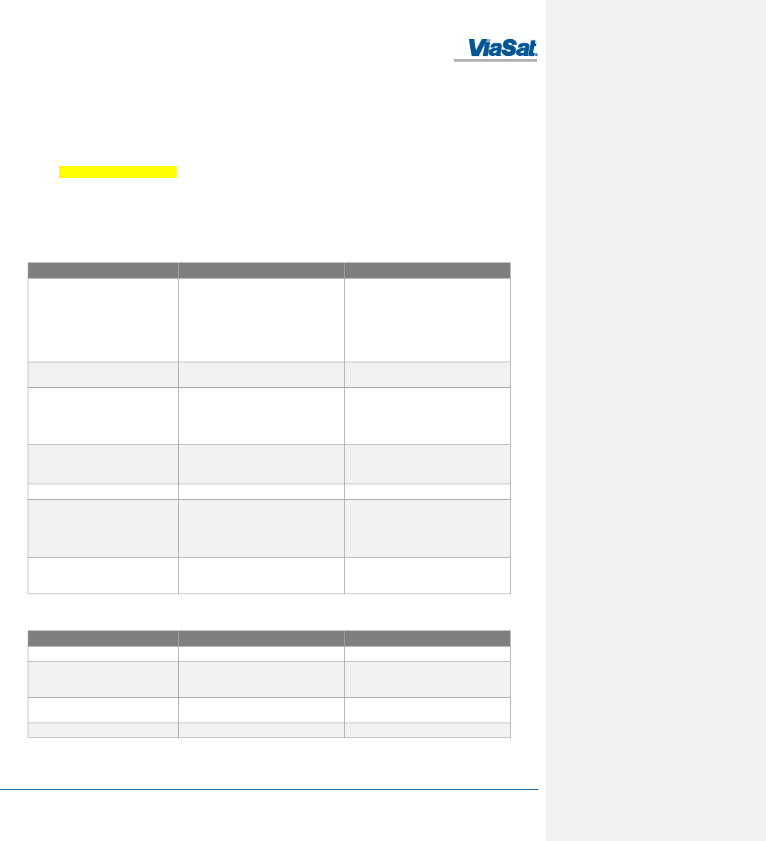
Table 5-1. Troubleshooting Guide
Problem/Observation
Possible Cause
Corrective Action
Cannot access terminal web server
Terminal not Power on
Incorrect IP address
Cable is not plugged in correctly
Default Ethernet IP address is
192.168.1100.1
Default WLAN IP address is 192.168.200.1.
Verify that cable is connected to user device
LAN port. Verify the the WLAN settings are
correct.
Terminal not responding to web server
interface
Software error
Power Cycle Terminal
Web Server shows no position fix
Terminal position is unknown, GNSS signal is
weak
Provide terminal with unobstructed view of
sky as much as possible. Try to point
terminal straight upward to receive GPS fix,
then repoint terminal toward L-band
satellite.
Web MMI status show terminal does
not exit searching mode
Receive signal strength is too low
View toward satellite is blocked
Repoint antenna (see Error! Reference
source not found.).
Ensure that no object is in front of antenna.
WiFi Connection cannot be established
Your device is too far from terminal
Terminal cannot login or Terminal does
not exit searching mode
No signal or weak signal
Interference
Provide terminal with unobstructed view of
sky as much as possible. Perform antenna
pointing as necessary.
Move terminal away from nearby satellite
terminals.
No signal or weak signal
Provide terminal with unobstructed view of
sky as much as possible. Perform antenna
pointing as necessary.
Faults may be visually observed as error codes on the Web MMI Status page as described in Table 5-2.
Table 5-2. Web MMI Fault Codes
Fault Code
Description
Recommended Action
0x01 - 0x53
General fault
Reboot the terminal.
0x61 - 0x63
Overtemp fault
Place terminal in environment less than
+70°C and power off until terminal cools
down.
0x69 -0x6B
Undertemp fault
Place terminal in environment greater than -
40°C until terminal warms up.
0x70 or other
Power fault
Reboot the terminal.
FT2225 Terminal User Manual
1215301, Rev. 001 ViaSat Proprietary Information 5-2
5.2 Preventive Maintenance
Preventative maintenance is the systematic, scheduled care and inspection of equipment to prevent equipment
failure and to reduce downtime. The primary preventative maintenance for the FT2225 is to keep the equipment
clean and dust free. Use a soft brush, moist sponge, and a clean cloth for this purpose. The radome should be
visually inspected for any attached substances which could potentially obstruct functionality (e.g., mud on the
radome).
In addition, to ensure proper functionality and full operating potential of FT2225 Terminal capabilities, the unit
should be visually inspected for cracks, corrosion, and loose mating connector.
5.3 Warranty
For warranty information and repairs, please contact your service provider.
5.4 Serviceable Parts
The FT2225 terminal contains no user-serviceable parts.
5.5 Customer Support
Customers can contact ViaSat with questions at:
ViaSat Customer Care Center
Toll Free +1 888 272-7232
Tel +1 760 476-2600
Cms.cbdnoc@viasat.com
Product Orders
To order ViaSat Terminals and accessories, contact:
M2Minquiries@viasat.com
Tel +1 760 893-2995
World Wide Web
Customers can obtain ViaSat Terminal information on ViaSat’s web page at:
http://www.viasat.com/m2m
Mailing Address
ViaSat, Inc.
6155 El Camino Real
Carlsbad, CA 92009-1602
USA
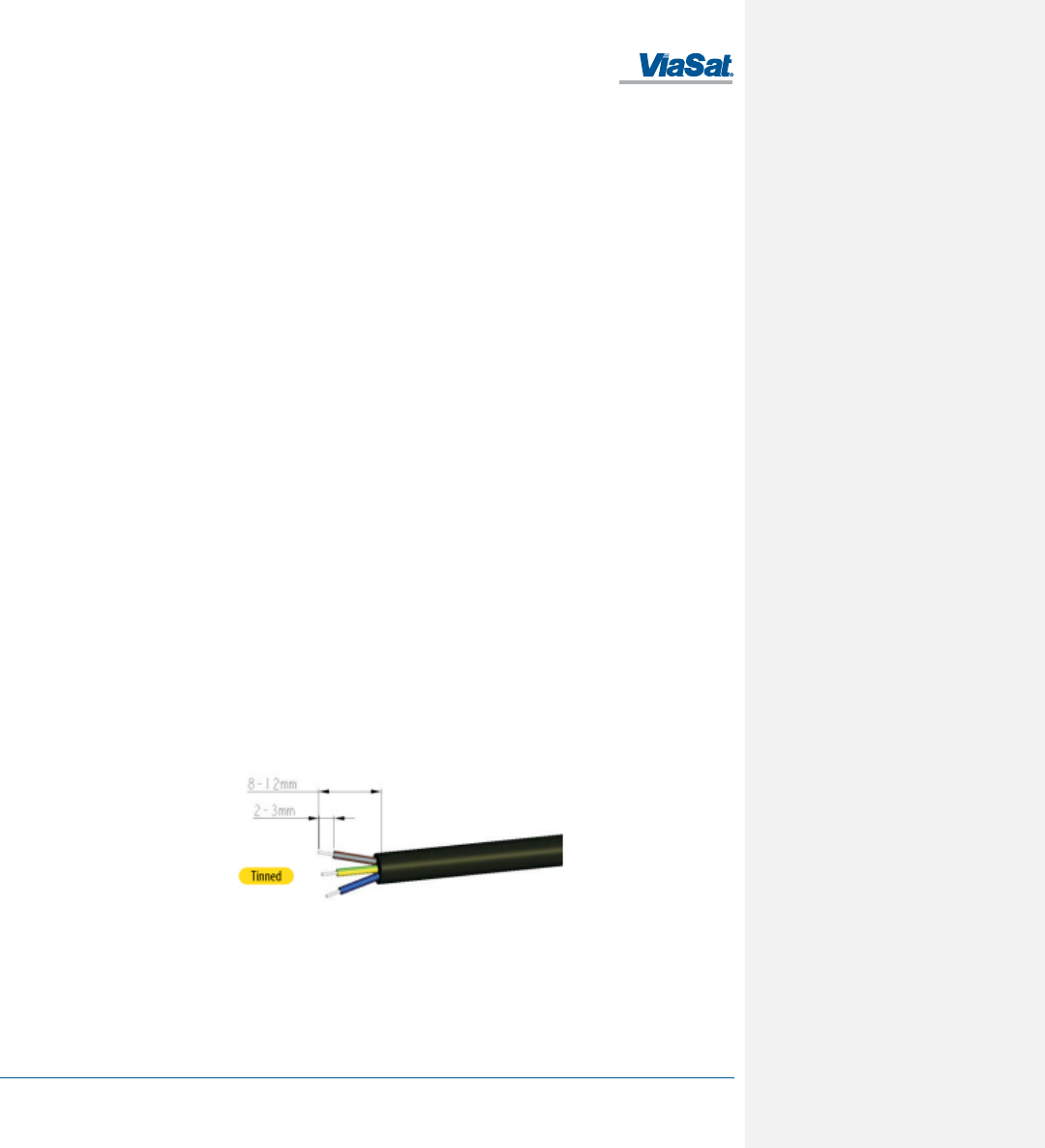
FT2225 Terminal User Manual
1215301, Rev. 001 ViaSat Proprietary Information A-1
Appendix A Power/Ethernet Cable Assembly Instruction
This section provides guidelines for the Value-Added Resellers or end-user to assemble the power/Ethernet cables.
The solder cup connector kit ships with the terminal.
A.1 Required Tools
The following tools are required to assemble the power/Ethernet cable:
• Utility knife or similar
• 22-26 AWG wire stripper
• Diagonal cutters
• Long-nose pliers
• Soldering iron and solder
A.2 Connector Information
The mating connector is a Chogori 12-pin connector and the part number is 22012211-01.
A.3 Cable Specification
The cable selection for this application is influence by three main principles: current capacity, outdoor application
and shielding.
The operating input voltage range for the terminal is 9 to 32 VDC and draws 1.7 amperes. If the application requires
an extended cable length, it is necessary to calculate the cable voltage drop to determine if the terminal is able to
receive the minimum 9 volts for operation.
Exposure to outdoor elements can degrade the insulation of the cable and allow moisture to penetrate the
conductor and subsequently degrade the copper conductor. It’s highly recommended that the cable chosen shall be
able to withstand UV rays.
Cable shielding is a critical design element over long distance. The cable selection can adversely be affected by
EMI/RFI/ESI. Ideally, multi-shield (foil & braid) is recommended. This design has superior shielding characteristics
from signal interferences.
A.4 Cable Assembly Steps
Use a utility knife to remove 12mm of the outer jacket of the cable and use diagonal cutters to remove any shielding
as shown in Figure A-1. Carefully remove 2-3mm of insulation from the wires using a wire stripper. Avoid nicking the
center conductor as you strip the insulation from the wire.
Figure A-1. Cable Assembly Preparation
The bare ends on the stripped wire may require twisting to prevent fraying when the connector parts are slid over
the cable. Slide the items over the cable in sequential order as shown in Figure A-2. Observe that the seal ring and
red gasket are present.
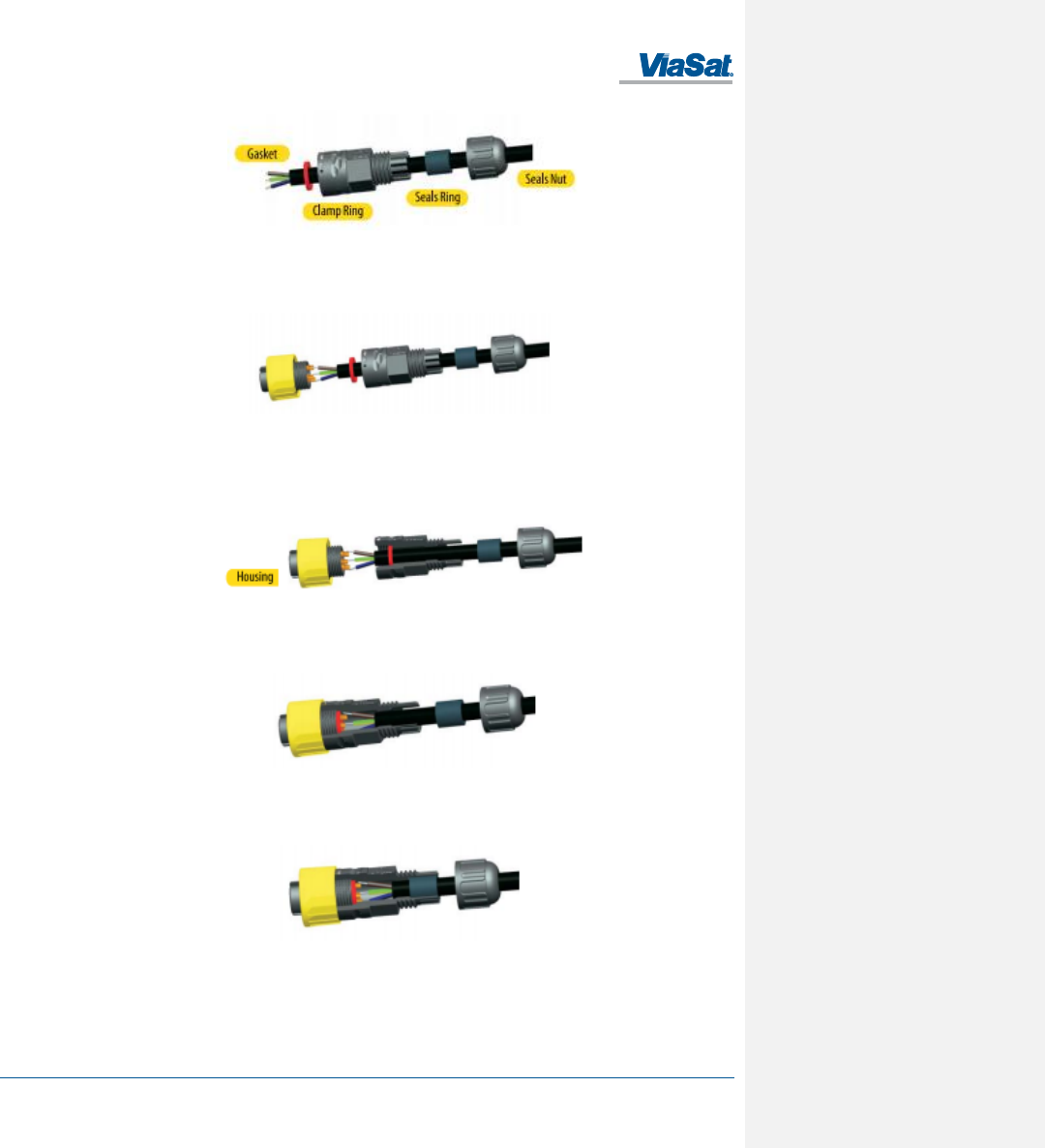
FT2225 Terminal User Manual
1215301, Rev. 001 ViaSat Proprietary Information A-2
Figure A-2. Connector Part Description
Apply a thin coat of solder for tinning on the bare wires and on the connector socket contacts in preparation of
soldering the wires to the end connector contacts as shown in Figure A-3.
Figure A-3. Cable Assembly - Step 1
Assemble the gasket into the clamp ring. The gasket is directional and the flat surface should be installed on the
housing side as shown in Figure A-4.
Figure A-4. Cable Assembly - Step 2
Assemble the clamp ring to the housing as shown in Figure A-5.
Figure A-5. Cable Assembly - Step 3
Slide the seal ring to the end of the clamp ring as shown in Figure A-6.
Figure A-6. Cable Assembly - Step 4
Assemble the seal nut and clamp ring as shown in Figure A-7.
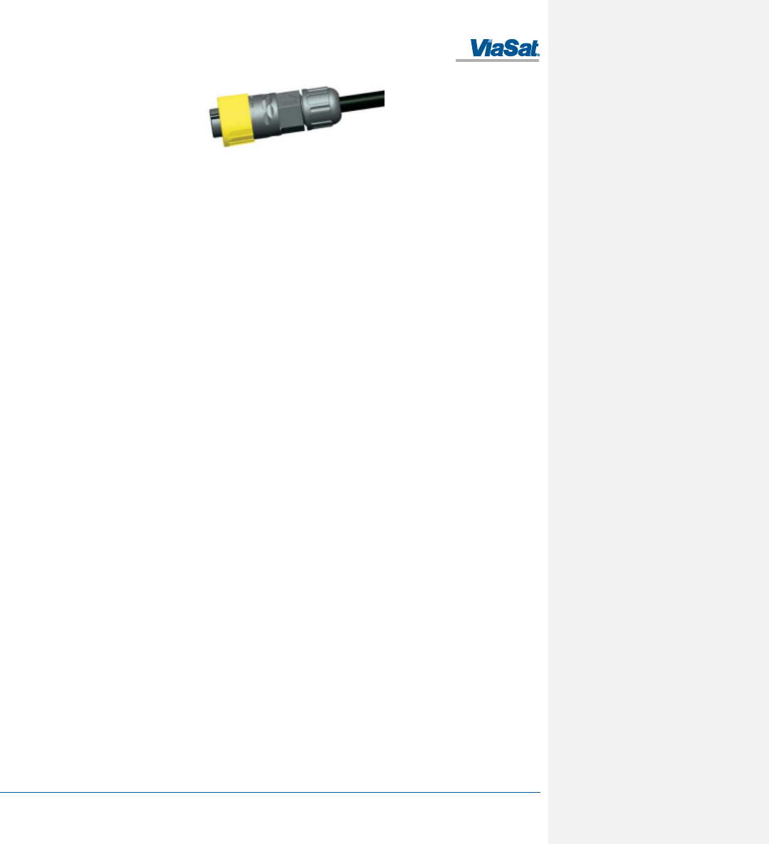
FT2225 Terminal User Manual
1215301, Rev. 001 ViaSat Proprietary Information A-3
Figure A-7. Cable Assembly - Step 5
FT2225 Terminal User Manual
1215301, Rev. 001 ViaSat Proprietary Information B-1
Appendix B Pole Mount
The FT2225 can be mounted on any flat surface that is wide as the bottom outline as shown in Figure 4 and installed
onto a pole using the pole mount adapter.
Instructions are included to install the terminal on any vertical position on a pole or on a horizontal support. The
vertical pole or horizontal support must have sufficient height to achieve an unobstructed view to the satellite.
B.1 Required Tools
The following tools are required to assemble and attach the terminal to a pole.
• Crescent wrench
• Philips screwdriver
• Flat blade screwdriver
• Pliers
B.2 Required Materials
The following materials are required to assemble and attach the terminal to a pole.
• Pole mount adapter and kit
• Stainless steel hose clamps
• Hardware kit
B.3 Installation Steps
The following are the installation steps to assemble and attach the terminal to a pole.
1. Audit the antenna bracket hardware kit.
2. Remove the bracket parts from the hardware kit.
3. Pre-assemble the pieces to prepare for installation.
4. Attach the upper bracket assembly and terminal adapter to the mounting pole.
5. Attach the lower bracket assembly to the antenna support/mounting pole.
6. Attach the FT2225 terminal to the adapter plate and secure bolts/nuts.
7. Adjust terminal adapter plate in the direction of the satellite and ensure there is no obstructed view to the
satellite.
8. Tightened the bolts and nuts at the joints.
9. Route and secure FT2225 cable assembly along the pole using metal tie mounts. Use self-tapping screws to
secure the metal tie mounts to the pole.
10. Install the cable assembly to the metal tie mounts and secure using black cable ties. A cable service loop may be
required at joints to allow re-pointing of the terminal.
11. Leave a cable service loop/slack at the FT2225 connector to ease connector termination. This will allow the
installer to re-terminate the connector with ease.
FT2225 Terminal User Manual
1215301, Rev. 001 ViaSat Proprietary Information C-1
Appendix C Roof Mount Example
The FT2225 can be installed on any flat surface that is wide as the bottom outline, as shown in Figure xx.
Comment [PT3]: Need the roof mount
graphic
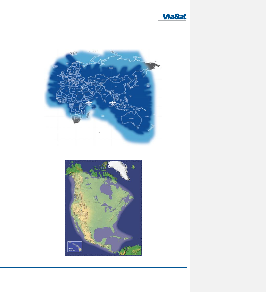
FT2225 Terminal User Manual
1215301, Rev. 001 ViaSat Proprietary Information D-1
Appendix D Satellite Coverage Maps
Figure D-1 shows the Thuraya satellite coverage map and Figure D-2 shows the LightSquared SkyTerra-1 satellite
coverage map.
Figure D-1. Thuraya Satellite Coverage Map
Figure D-2. LightSquared SkyTerra-1 Satellite Coverage Map
FT2225 Terminal User Manual
1215301, Rev. 001 ViaSat Proprietary Information E-1
Appendix E VMS Pointing Procedure
CAUTION: Do not attempt to point the FT2225 to a satellite during a rain/thunder storm. Doing
so can cause personal casualty or damage the equipment.
A Satellite finder application for your smart phone is the easiest method to locate a geostationary satellite wherever
you are. The recommended Satellite Pointing Programs for smartphones are listed below.
iPhone
Satellite Locator: https://itunes.apple.com/us/app/satellitelocator/id540894938?mt=8
Dish Pointer: https://itunes.apple.com/us/app/dishpointer-ar-pro/id321914743?mt=8
Android
Satellite Director: https://play.google.com/store/apps/details?id=zekitez.com.satellitedirector&hl=en
Satellite Pointer: https://play.google.com/store/apps/details?id=com.tda.satpointer&hl=en
Dish Pointer: https://play.google.com/store/apps/details?id=com.dishpointer.dparpro&hl=en
The FT2225 antenna peaking procedure is used to ensure the terminal has an unobstructed LOS to the satellite.
1. Enable your Satellite Finder/Locater apps on our mobile phone and point to the sky.
2. Move your mobile phone up and down and left and right to get a satellite arc on a live video display. You wi ll
see satellites line up along the arc and see if there are any obstructed buildings/trees blocking the line of sight.
3. Place the FT2225 terminal/support in a spot where the Satellite Finder has an unobstructed LOS to the satellite
to begin antenna peaking.
4. View Section 3.3 Status Page and observe the Es/No reading.
5. Very slowly optimize the FT2225 in azimuth from east to west direction and observe the Es/No reading. The
Es/No should be at a maximum signal when peaked.
6. Repeat step 2 for elevation direction.
7. Once it is apparent that the signal does not increase in signal, make a mark on the antenna mount to indicate it
is peaked in azimuth and elevation.
8. Tighten the azimuth and elevation bolts or clamp bolts.
9. If necessary, repeat these steps to confirm the FT2225 is peaked.