ViaSat VSC100 24GHz Satcom Road Speed Detector/Commercial Vehicles User Manual
ViaSat, Inc. 24GHz Satcom Road Speed Detector/Commercial Vehicles Users Manual
ViaSat >
Users Manual
- 1 -
VELOCITY SENSING CONTROLLER
MODEL 100 (VSC100)
OWNER’S MANUAL
ViaSat - Digital Communication Products and Services for Commercial and Government Markets
- 2 -
ViaSat, Incorporated
Advanced Microwave Products
1388 North Tech Blvd.
Gilbert, AZ 8533
Office: +1 480-503-5505
Fax: +1 480-503-5501
ViaSat, Inc.
Headquarters
6155 El Camino Real
Carlsbad, CA 92009
Copyright 2014 © ViaSat, Inc. All rights reserved. No part of this work may be
reproduced, published, or distributed in any form or by any means (electronically,
mechanically, photocopying, recording, or otherwise), or stored in a database
retrieval system, without the prior written permission of ViaSat Incorporated in
each instance.
- 3 -
Table of Contents
TABLE OF CONTENTS ............................................................................................................................. 3
DOCUMENT REVISION HISTORY ........................................................................................................ 3
1
INTRODUCTION ................................................................................................................................ 4
2
PRECAUTIONS ................................................................................................................................... 4
3
PRODUCT DESCRIPTION ................................................................................................................ 4
4
INSTALLATION ................................................................................................................................. 5
5
CONNECTOR ...................................................................................................................................... 6
Document Revision History
Version Date Author Contributors Change Tracker Description
001 12/23/13 D. Saunders Initial Release
Status: (click appropriate checkbox) Document No: 1183141
Initial Draft Version: 001
Working Draft Date: 12/23/13
Pilot
Released
Revision to Released
- 4 -
1 Introduction
These instructions provide important information to the users of the ViaSat Velocity
Sensing Controller Model 100, or VSC100. By following these instructions, the VSC100
will function properly over its lifetime. If these instructions are not followed, the VSC100
may malfunction and/or have a limited lifetime.
2 Precautions
All installation, adjustment, or removal of the VSC100 should be undertaken by trained
personnel who are trained in safety regulations for the system.
This device complies with Part 15 of the FCC rules and carries the FCC ID is 2ABLP-
VSC100. Operation is subject to the following two conditions: (1) this device may not
cause harmful interference, and (2) this device must accept any interference received,
including interference that may cause undesired operation. Any unauthorized changes
or modifications to the VSC100 could void the user’s authority to operate the
equipment in the system.
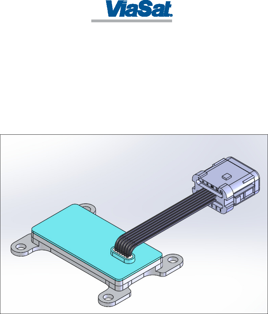
3 Product Description
The VSC100 includes an environmentally protective metal housing and plastic cover
with wire harness as shown in Figure 1.
Figure 1 – VSC100
- 5 -
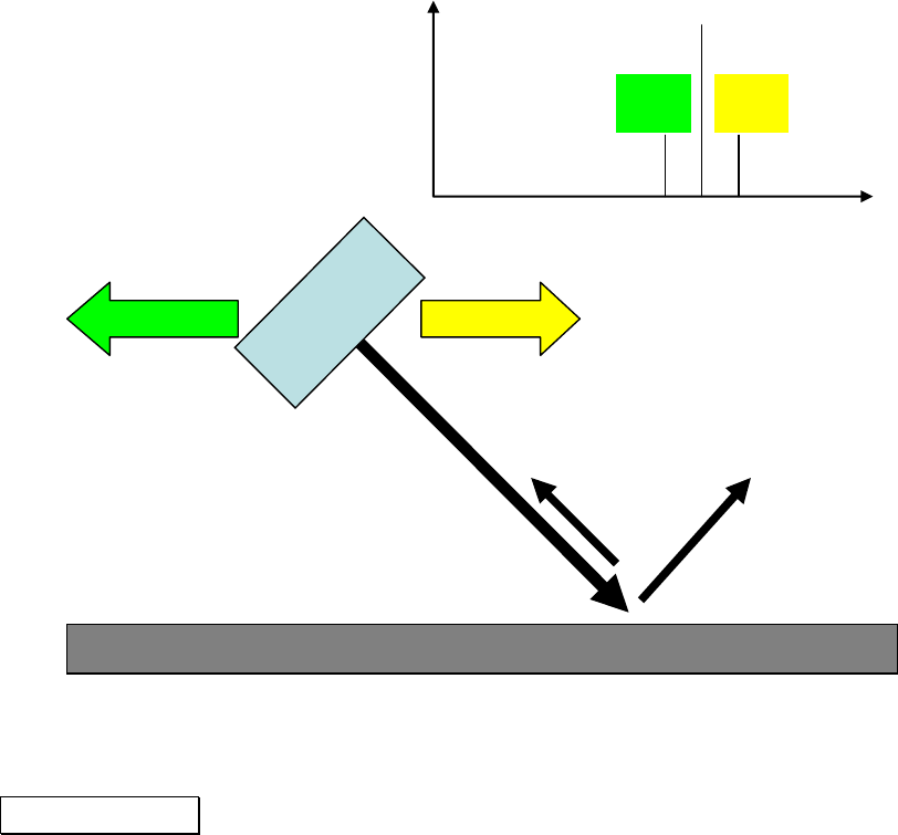
The VSC works using the Doppler principal. The sensor is pointed toward a road surface
and transmits energy, some of which is scattered back to the VSC and received. If there is
motion of the VSC with respect to the scatterers on the road surface, the received
frequency will be offset from the transmitted frequency directly proportional to the
velocity of the relative motion. As shown in Figure 2, the received frequency for motion
"away" from the scatterers causes a decrease in frequency, while motion "toward" the
scatterers causes an increase in frequency. The VSC100 measurement of frequency also
depends on the installation angle with respect to the horizon, so care must be taken to
ensure proper installation.
Radar
Sensor
Road Surface
Frequency
Tx
Motion
Rx
Motion
Rx
Figure 2 – Velocity Sensing Using Doppler
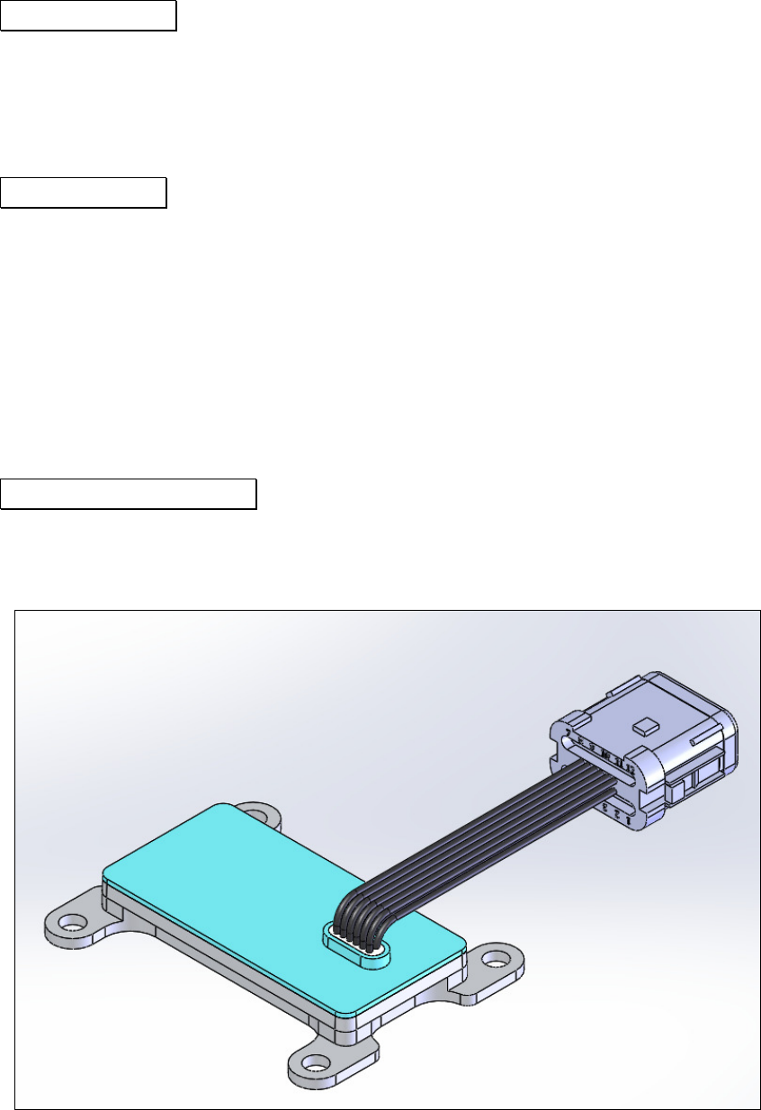
4 Installation
The VSC100 typically mounts 1 meter above the ground on a bracket firmly attached to
the under structure of the vehicle. It is oriented so that the plastic cover is pointing
towards the rear of the vehicle at an angle of 30 degrees with respect to horizontal with
the cable harness tied so that it does not obstruct the path from the VSC100 to the ground,
as shown below in Figure 3.
- 6 -
Figure 3 – VSC100 Mounting
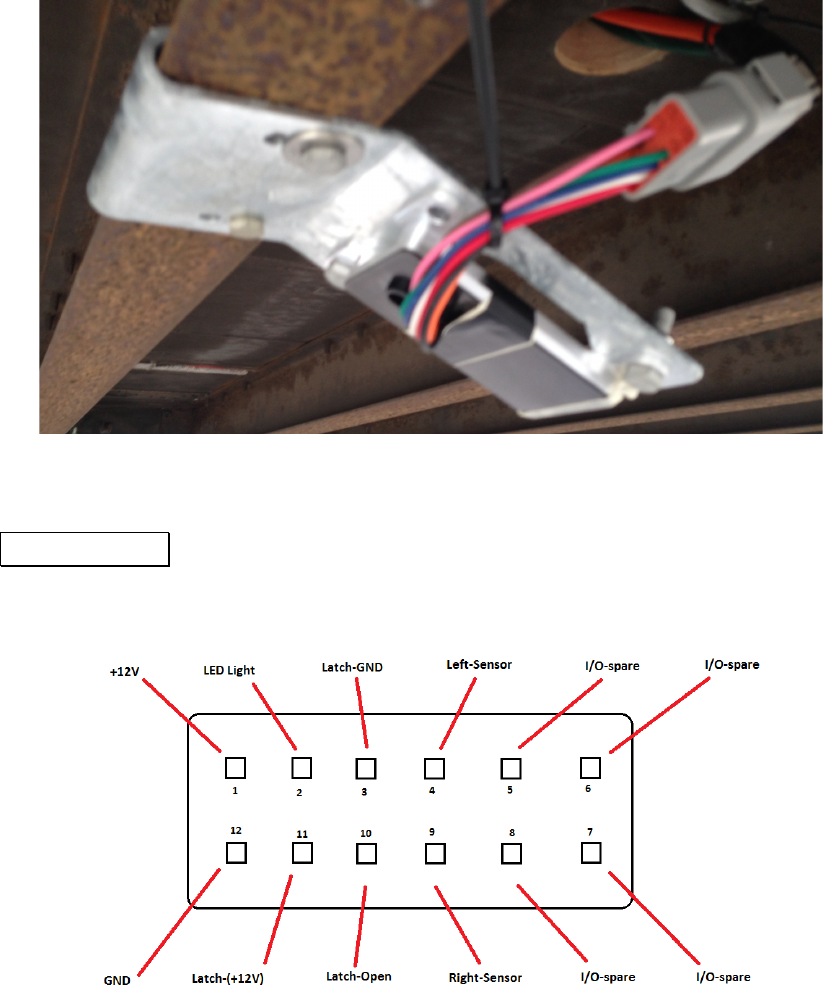
5 Connector
The VSC100 connector is shown below in Figure 4.
Figure 4 – VSC100 Connector
When used in a system, the VSC100 is connected to a 12 volt power system, an indicator
light, and two electromechanical latches. The wiring diagram is shown below in Figure 5.
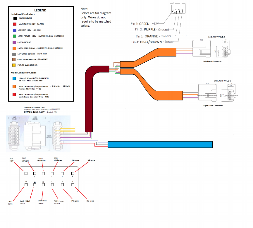
- 7 -
Figure 5 – Wiring Harness