Vibration Research OBSERVR1000 Portable Data Acquisiition and Analyzer User Manual 2017 09 11 ObserVIEWHelp
Vibration Research Corporation Portable Data Acquisiition and Analyzer 2017 09 11 ObserVIEWHelp
UserManual.wiki
>
Vibration Research
>
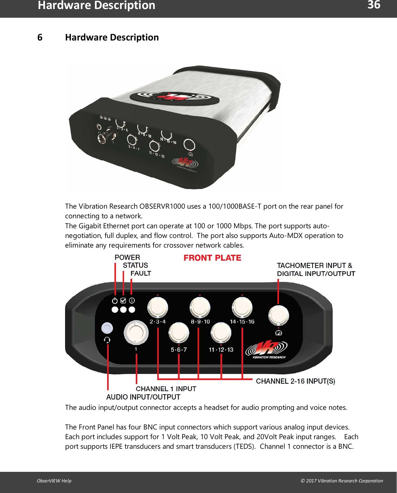
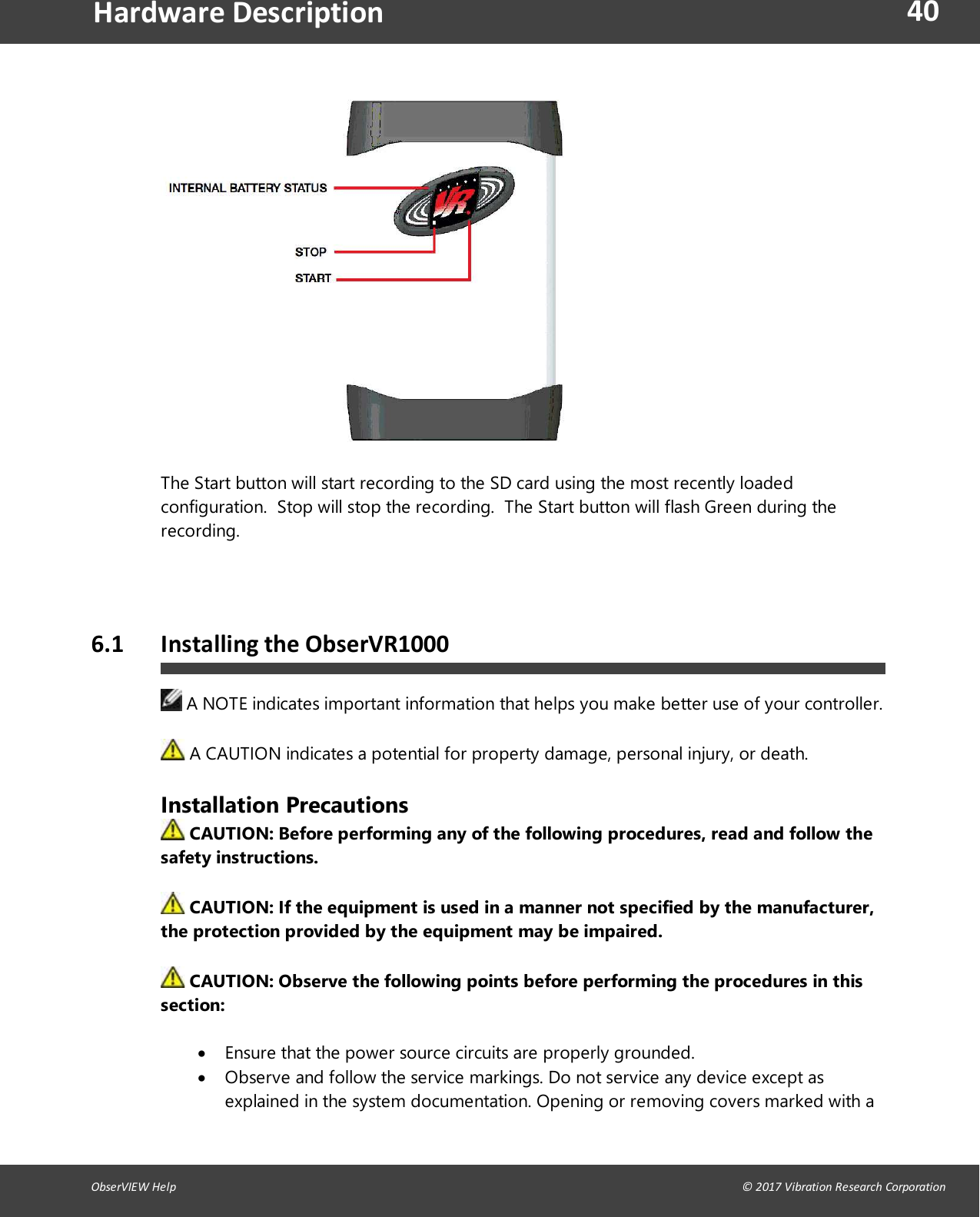
OBSERVR1000 User Manual
User Manual
Navigation menu
Upload a User Manual
Namespaces
Wiki Guide
HTML
PDF
Info
Views
User Manual
Discussion / Help
Navigation