Vibration Research OBSERVR1000 Portable Data Acquisiition and Analyzer User Manual 2017 09 11 ObserVIEWHelp
Vibration Research Corporation Portable Data Acquisiition and Analyzer 2017 09 11 ObserVIEWHelp
User Manual

®
ObserVIEW Help
USER MANUAL
© 2017 Vibration Research Corporation

2
ObserVIEW Help © 2017 Vibration Research Corporation
Table of Contents
1. Document Revision 4
2. Getting Started 6
2.1 Connecting and Disconnecting to Remote Devices ............................................................. 7
2.2 Inputs .................................................................................................................................... 7
2.3 Opening and Closing VFW Files ........................................................................................... 8
2.4 Exporting a File ..................................................................................................................... 9
2.5 File Properties ...................................................................................................................... 9
2.6 User Settings ....................................................................................................................... 10
3. Viewing a File 12
3.1 Main Graph ......................................................................................................................... 13
3.2 Summary Graph ................................................................................................................. 14
3.3 Cursors ................................................................................................................................ 15
3.4 Traces .................................................................................................................................. 16
3.5 Adding and Removing Graphs ........................................................................................... 17
3.6 Editing Traces and Axes ..................................................................................................... 18
3.7 FFT Graph Analysis ............................................................................................................. 18
3.8 Graph Manipulation ........................................................................................................... 19
3.9 Replay Graph ...................................................................................................................... 22
4. Editing a File 23
4.1 Sections ............................................................................................................................... 24
4.2 Selection Points .................................................................................................................. 25
4.3 Editing the VFW .................................................................................................................. 26
4.4 Edit Point Options .............................................................................................................. 28
4.5 End Point Options .............................................................................................................. 30
5. Notifications 31
5.1 Error Notifications ............................................................................................................. 32
Copy Error Notification ............................................................................................... 325.1.1
Delete File Failure Notification ................................................................................... 325.1.2
Export Error Notification ............................................................................................. 325.1.3
File Access Error Notification ...................................................................................... 325.1.4
File Append Failure Notification ................................................................................. 325.1.5
Graph Load Failure Notification ................................................................................. 325.1.6
Invalid File Notification ............................................................................................... 325.1.7

3
ObserVIEW Help © 2017 Vibration Research Corporation
Table of Contents
Invalid VFW Data Notification .................................................................................... 335.1.8
Malformed File Notification ....................................................................................... 335.1.9
Missing VFW Data Notification ................................................................................... 335.1.10
Overwrite File Error Notification ................................................................................ 335.1.11
Paste Failure Notification ........................................................................................... 335.1.12
Primary Source Add Failure Notification .................................................................... 335.1.13
Temporary File Not Found Notification ..................................................................... 335.1.14
VFW Read Error Notification ....................................................................................... 335.1.15
Create Edit Session Error Notification ........................................................................ 335.1.16
Help File Error .............................................................................................................. 335.1.17
5.2 Information Notifications .................................................................................................. 33
Cut All Not Allowed Notification ................................................................................ 335.2.1
File Missing Notification ............................................................................................. 345.2.2
Incompatible File Notification .................................................................................... 345.2.3
Successful Export Notification .................................................................................... 345.2.4
Successful Registration Notification ........................................................................... 345.2.5
6. Hardware Description 35
6.1 Installing the ObserVR1000 ............................................................................................... 40
6.2 Hardware Safety Documentation ...................................................................................... 42
6.3 Cables, Port Connections, and Pinout Information .......................................................... 43
6.4 RJ45 Connections ............................................................................................................... 46
6.5 Physical Dimensions .......................................................................................................... 47
6.6 Using The Battery ............................................................................................................... 47
7. Appendix 49
7.1 About ObserVIEW .............................................................................................................. 50
7.2 Microsoft Public License (Ms-PL) ....................................................................................... 52

35
ObserVIEW Help © 2017 Vibration Research Corporation
Hardware Description
36
ObserVIEW Help © 2017 Vibration Research Corporation
Hardware Description
6 Hardware Description
OBSERVR1000 Front and Back Panel Port Description
The Vibration Research OBSERVR1000 uses a 100/1000BASE-T port on the rear panel for
connecting to a network.
The Gigabit Ethernet port can operate at 100 or 1000 Mbps. The port supports auto-
negotiation, full duplex, and flow control. The port also supports Auto-MDX operation to
eliminate any requirements for crossover network cables.
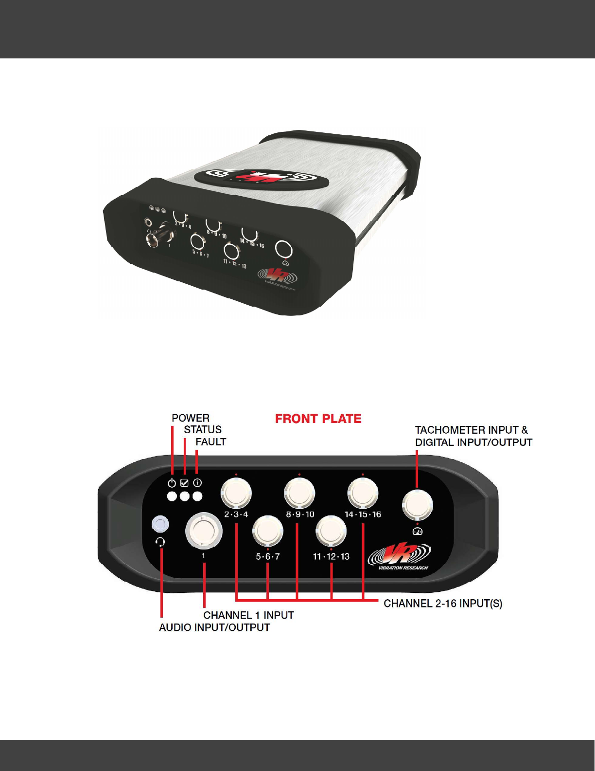
The audio input/output connector accepts a headset for audio prompting and voice notes.
The Front Panel has four BNC input connectors which support various analog input devices.
Each port includes support for 1 Volt Peak, 10 Volt Peak, and 20Volt Peak input ranges. Each
port supports IEPE transducers and smart transducers (TEDS). Channel 1 connector is a BNC.

37
ObserVIEW Help © 2017 Vibration Research Corporation
Hardware Description
Channels 2-16 connectors are triaxial. Each connector supports 1 triaxial transducers, or 3
single axis transducer. Microphones, and external conditioners are some of the supported
signals and transducers than would use these 6 connectors.
The Tachometer connector includes a configurable 2 channel tachometer. The tachometer
channels can be combined for quadrature mode or used as independent tachometers. The
tachometer signals can be configured for low-impedance hall effect magnetics of up to +/-
30Volts peak. Included with the tachometer connector is a single TTL discrete input and a
single TTL discrete output. The connector is capable of supplying 100mA at 5VDC to
condition the input signals.
The three indicators provide operator status.
The Power Indicator is green when the main CPU is running and the external battery is not
connected and the internal battery is at greater than 10% capacity. Power Indicator is red
when the main CPU is running and the external battery is not connected and the internal
battery is at or below 10% capacity. Power Indicator is off when the main CPU is off or held in
reset.
The Power Indicator will blink ten (10) times with a period of 200msec, 50% duty cycle, when
the OBSERVR1000 shuts down, or is prevented from turning on, due to extreme
temperatures. Power Indicator blinks with a period of 800ms and a duty cycle of 50%, for a
minimum of three (3) flashes, when the OBSERVR1000 is powering down. Power Indicator is
green when the main CPU is running and the external battery is connected and is not
detected as having a low voltage. Power Indicator is yellow when the main CPU is running
and the external battery is connected and is detected as having a low voltage.
Power Indicator is red when the main CPU is running and the external battery is connected
and is detected as near shutdown voltage.
The Status indicator is green when all input channels which are configured to record are
connected properly. The Status indicator is red if any input channel configured to record is
disconnected or faulted.
The System Fault indicator is red when system fault is detected.
38
ObserVIEW Help © 2017 Vibration Research Corporation
Hardware Description
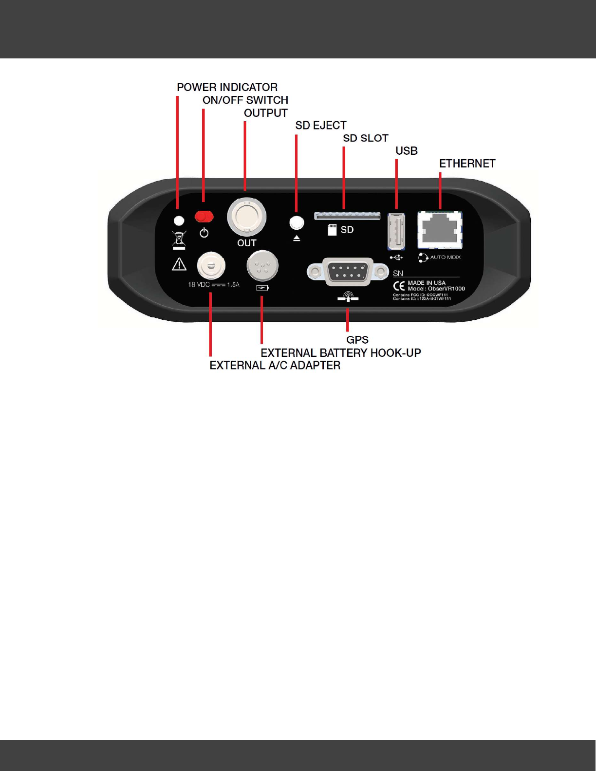
The Power Indicator to the left of the on/off power switch shows the same states as the
power indicator on the front panel. It is green when the main CPU is running and the external
battery is not connected and the internal battery is at greater than 10% capacity. Power
Indicator is red when the main CPU is running and the external battery is not connected and
the internal battery is at or below 10% capacity. Power Indicator is off when the main CPU is
off or held in reset.
The Power Indicator will blink ten (10) times with a period of 200msec, 50% duty cycle, when
the OBSERVR1000 shuts down, or is prevented from turning on, due to extreme
temperatures. Power Indicator blinks with a period of 800ms and a duty cycle of 50%, for a
minimum of three (3) flashes, when the OBSERVR1000 is powering down. Power Indicator is
green when the main CPU is running and the external battery is connected and is not
detected as having a low voltage. Power Indicator is yellow when the main CPU is running
and the external battery is connected and is detected as having a low voltage.
Power Indicator is red when the main CPU is running and the external battery is connected
and is detected as near shutdown voltage.
Activating the Power Switch for 1 second or more while the OBSERVR1000 is off will turn it
on. Activating the Power Switch for 2 seconds or more while the OBSERVR1000 is on will turn

39
ObserVIEW Help © 2017 Vibration Research Corporation
Hardware Description
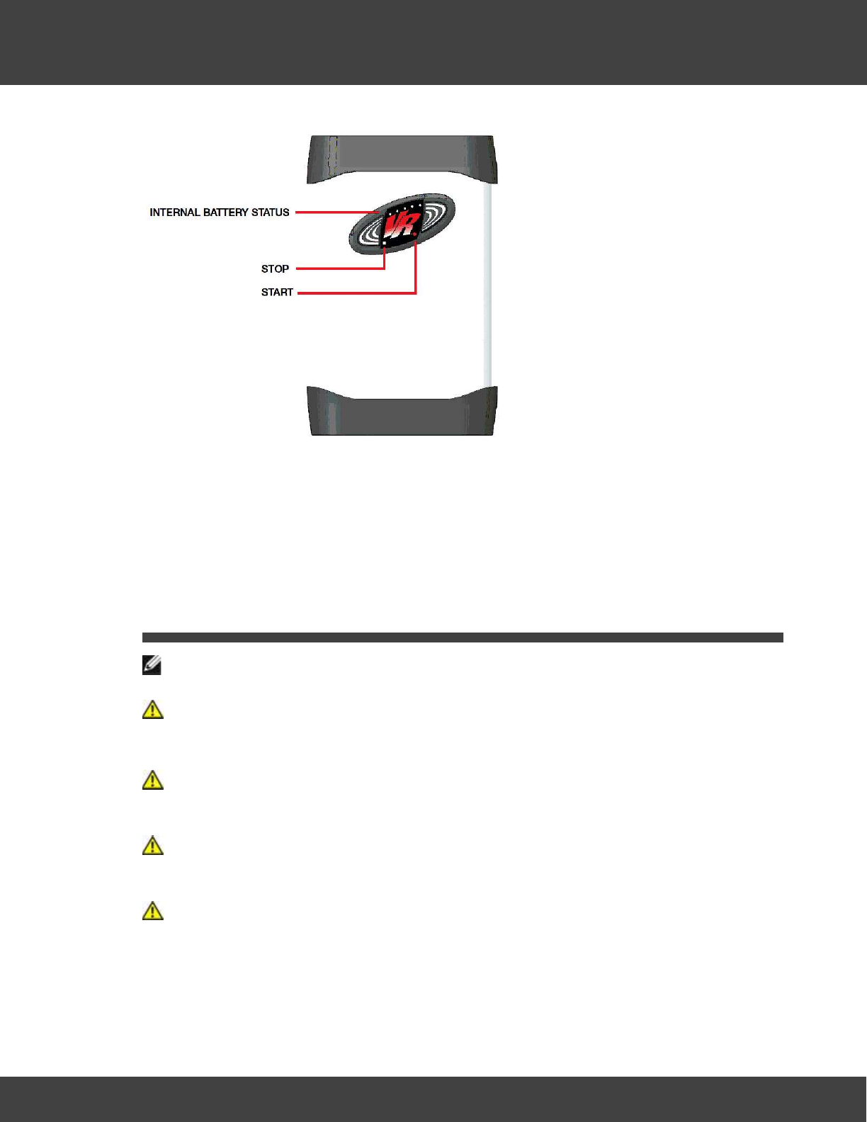
it off within 30 seconds. Momentarily activating the Power Switch will cause the Internal
Battery Status Indicator to display on the top of the OBSERVR1000.
The OUT connector can be used to drive external equipment. The connector is capable of
+/-10V signal and is typically used to synchronize or drive external complementary
equipment.
The SD Card provides storage for recorded data. The insertion and removal of the SD Card is
a manual operation. To insert the card press the card until it clicks. Remove the card
physically be pressing on the inserted card until it pops out. The lighted pushbutton to the
left of the SD card slot is used to allow safe removal of the SD Card. Although physically the
SD card may be removed at any time, you will need to allow the OBSERVR1000 to complete
any data written to the SD card prior to removal. The SD Eject button blinks RED while write
is active. The SD Eject button GREEN when not active/safe to remove. Press the SD Eject
button to prepare card for safe ejection, then wait for it to turn GREEN prior to physically
removing the SD Card.
The USB port connects to optional Vibration Research supplied data acquisition interfaces and
external hard drives. The USB port is capable of supplying 0.9Amps.
The GPS port connects to an optional Vibration Research supplied GPS. The GPS is powered
by the OBSERVR1000 and includes position updates at about 1Hz as well as GPS time base
syncronization.
The Ethernet port is a 10/100/1000BT capable AutoMDIX port to connect to an external
computer. This connection provides the ability to use the OBSERVR1000 tethered as a
dedicated data acquisition device. This is in addition to the stand alone operation.
40
ObserVIEW Help © 2017 Vibration Research Corporation
Hardware Description
The Start button will start recording to the SD card using the most recently loaded
configuration. Stop will stop the recording. The Start button will flash Green during the
recording.
6.1 Installing the ObserVR1000
A NOTE indicates important information that helps you make better use of your controller.
A CAUTION indicates a potential for property damage, personal injury, or death.
Installation Precautions
CAUTION: Before performing any of the following procedures, read and follow the
safety instructions.
CAUTION: If the equipment is used in a manner not specified by the manufacturer,
the protection provided by the equipment may be impaired.
CAUTION: Observe the following points before performing the procedures in this
section:
Ensure that the power source circuits are properly grounded.
Observe and follow the service markings. Do not service any device except as
explained in the system documentation. Opening or removing covers marked with a

41
ObserVIEW Help © 2017 Vibration Research Corporation
Hardware Description
triangular symbol with a lightning bolt may cause electrical shock. These components
are to be serviced by trained service technicians only.
Ensure that the power cable, extension cable, and/or plug is not damaged.
Ensure that the device is not exposed to water.
Ensure that the device is not exposed to radiators and/or heat sources.
Do not push foreign objects into the device, as it may cause a fire or electric shock.
Use the device only with approved equipment.
Ensure that the device does not overload the power circuits, wiring, and over-current
protection. To determine the possibility of overloading the supply circuits, add
together the ampere ratings of all switches installed on the same circuit as the device.
Compare this total with the rating limit for the circuit.
Do not install the device in an environment where the operating ambient
temperature might exceed 55ºC (131ºF).
Ensure that the airflow around the front, sides, and back of the device is not
restricted.
Site Requirements
Before installing the device, verify that the site selected for the device meets the following
site requirements:
Power — When charging the device or using AC power, install within 1.5 m (5 feet) of
a grounded, easily accessible outlet 100-240VAC Nominal VAC, 47-63 Hz.
General — When charging the device or using AC power, ensure that the power
supply is correctly installed.
Cabling — Cabling is routed to avoid sources of electrical noise such as radio
transmitters, broadcast amplifiers, power lines, and fluorescent lighting fixtures.
Ambient Requirements — The ambient device operating temperature range is -20 to
55 °C (-4 to 131 °F) at a relative humidity of up to 95%RH , non-condensing. Verify
that water or moisture cannot enter the device case.
Ambient Requirements — The ambient AC Adapter operating temperature range is 0
to 60 °C (32 to 140 °F).
Do not operate this product near volatile or flammable materials.
Unpacking
While unpacking the device, ensure that the following items are included:
The device
IEC C13 AC power cable
Software CD

42
ObserVIEW Help © 2017 Vibration Research Corporation
Hardware Description
6.2 Hardware Safety Documentation
Intended Use
The OBSERVR1000 is a high sensitivity, low noise, low voltage data recorder intended to be
used to record signals such as those generated by accelerometers and other sensors that
generate signals in the ±10v range.
Things to Note
The mains supply cord is part of the separately certified power supply. Vibration
Research is responsible for supplying the correct power supply for the country in
which it is sold.
The external power supply should not be supplied by other than Vibration Research.
The external power supply shall be double insulated and LPS rated.
Ensure any external circuits that provide a source of power connected to the unit, are
double or reinforced insulated from mains or separated from mains by basic
insulation plus a grounded shield and meet requirements for SELV (Separated or
Safety Extra-Low Voltage) levels (under 33Vrms/46.7Vpk or 70Vdc in normal
conditions and 55Vrms/78Vpk or 140Vdc single fault).
General Safety for the OBSERVR1000
To prevent the spread of fire, keep candles or other open flames away from this
product at all times.
Do not place your equipment in a closed-in wall unit or on a bed, sofa, or rug.
Keep your device away from radiators and heat sources.
Keep your equipment away from extremely hot or cold temperatures to ensure that it
is used within the specified operating range.
Do not push any objects into the air vents or openings of your equipment. Doing so
can cause fire or electric shock by shorting out interior components.
Avoid placing loose papers underneath your device.
Do not use your equipment in a wet environment, for example, near a bath tub, sink,
or swimming pool or in a wet basement.
Do not use AC powered equipment during an electrical storm. Battery powered
devices may be used if all cables have been disconnected.
Do not spill food or liquids on your equipment.
Before you clean your equipment, disconnect it from the electrical outlet. Clean your
device with a soft cloth dampened with water. Do not use liquids or aerosol cleaners,
which may contain flammable substances.
Do not operate your equipment with any cover(s) removed.
Do not use for any purpose other than those for which the unit is intended.

43
ObserVIEW Help © 2017 Vibration Research Corporation
Hardware Description
FCC Notices
This device complies with part 15 of the FCC Rules. Operation is subject to the following two
conditions: (1) This device may not cause harmful interference, and (2) this device must
accept any interference received, including interference that may cause undesired operation.
Changes or modifications not expressly approved by the party responsible for compliance
could void the user’s authority to operate the equipment.
Note: This equipment has been tested and found to comply with the limits for a Class A digital
device, pursuant to part 15 of the FCC Rules. These limits are designed to provide reasonable
protection against harmful interference when the equipment is operated in a commercial
environment. This equipment generates, uses, and can radiate radio frequency energy and, if
not installed and used in accordance with the instruction manual, may cause harmful
interference to radio communications. Operation of this equipment in a residential area is
likely to cause harmful interference in which case the user will be required to correct the
interference at his own expense.
This portable transmitter with its antenna has shown compliance with FCC’s SAR limits for
general population / uncontrolled exposure. The maximum listed SAR level is 1.07 W/kg
(body). The antenna used for this device must not be co-located or operating in conjunction
with any other antenna or transmitter.
Manufacturer
Vibration Research
1294 Chicago Drive,
Jenison, MI 49428 USA
6.3 Cables, Port Connections, and Pinout Information
This section explains the switch physical interfaces, and provides information about cables and
port connections.
44
ObserVIEW Help © 2017 Vibration Research Corporation
Hardware Description
BNC Input and Outputs
BNC connectors are manufactured with 50 and 75 ohm impedance capability. 50 Ohm cables
are typically used in this application. BNC Inputs are typically used with accelerometer.
Nominal ranging allows for maximum 20 Volts peak input devices. BNC output ranging
allows driving maximum 10V peak devices or maximum 1V peak devices.
Connecting and disconnecting Triaxial Input and Tachometer
Connectors
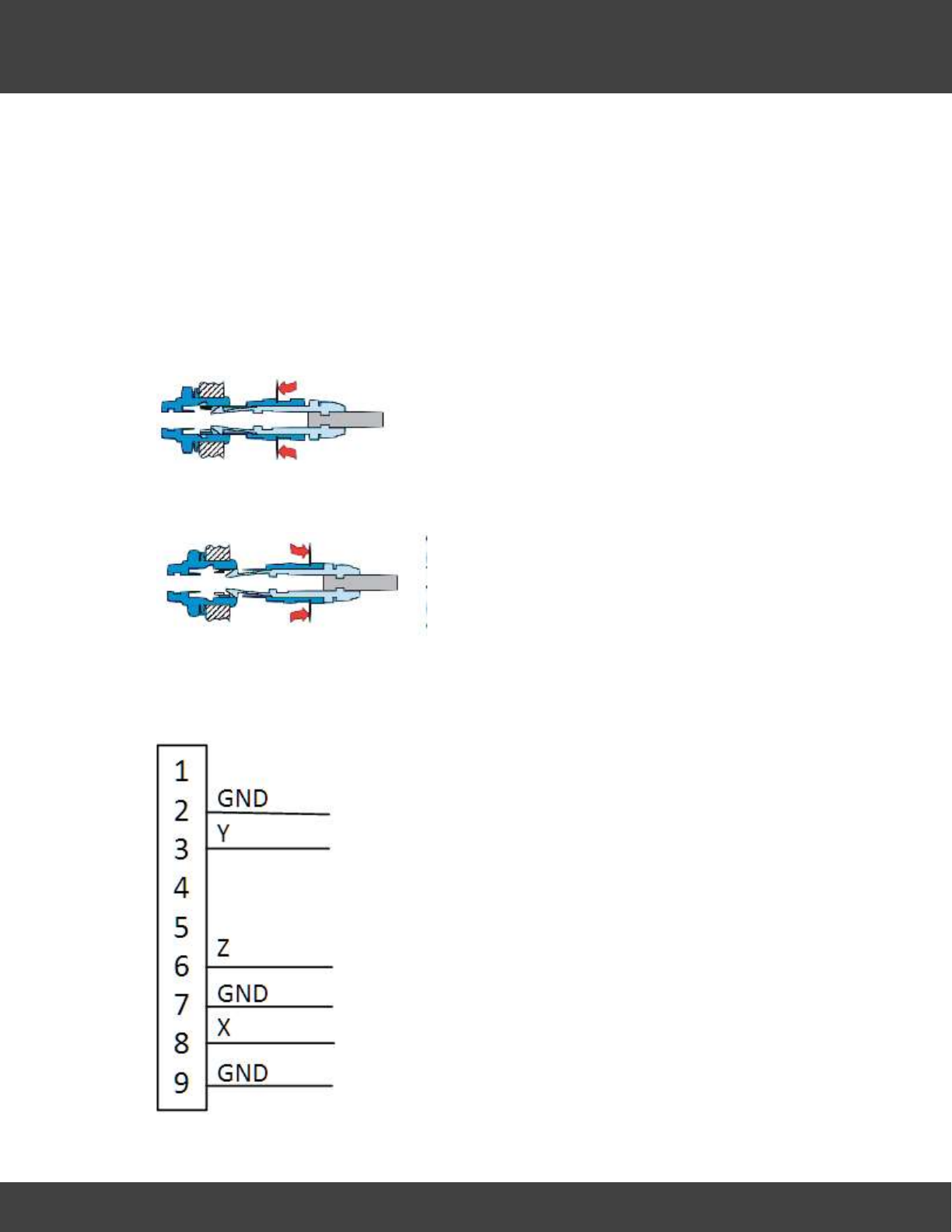
The self-latching system allows the connector to be mated by simply by aligning the red dot
on the connector with the red dot on the pushing the plug axially into the socket.
The connector is disengaged by a single axial pull on the outer release sleeve. This first
disengages the latches and then withdraws the plug from the socket.
Triaxial Input Connector
45
ObserVIEW Help © 2017 Vibration Research Corporation
Hardware Description
The lowest number channel is labeled X, second channel is labeled Y, highest numbered
channel is labeled Z. Nominal ranging allows for maximum 20 Volts peak input devices. BNC
output ranging allows driving maximum 10V peak devices or maximum 1V peak devices.
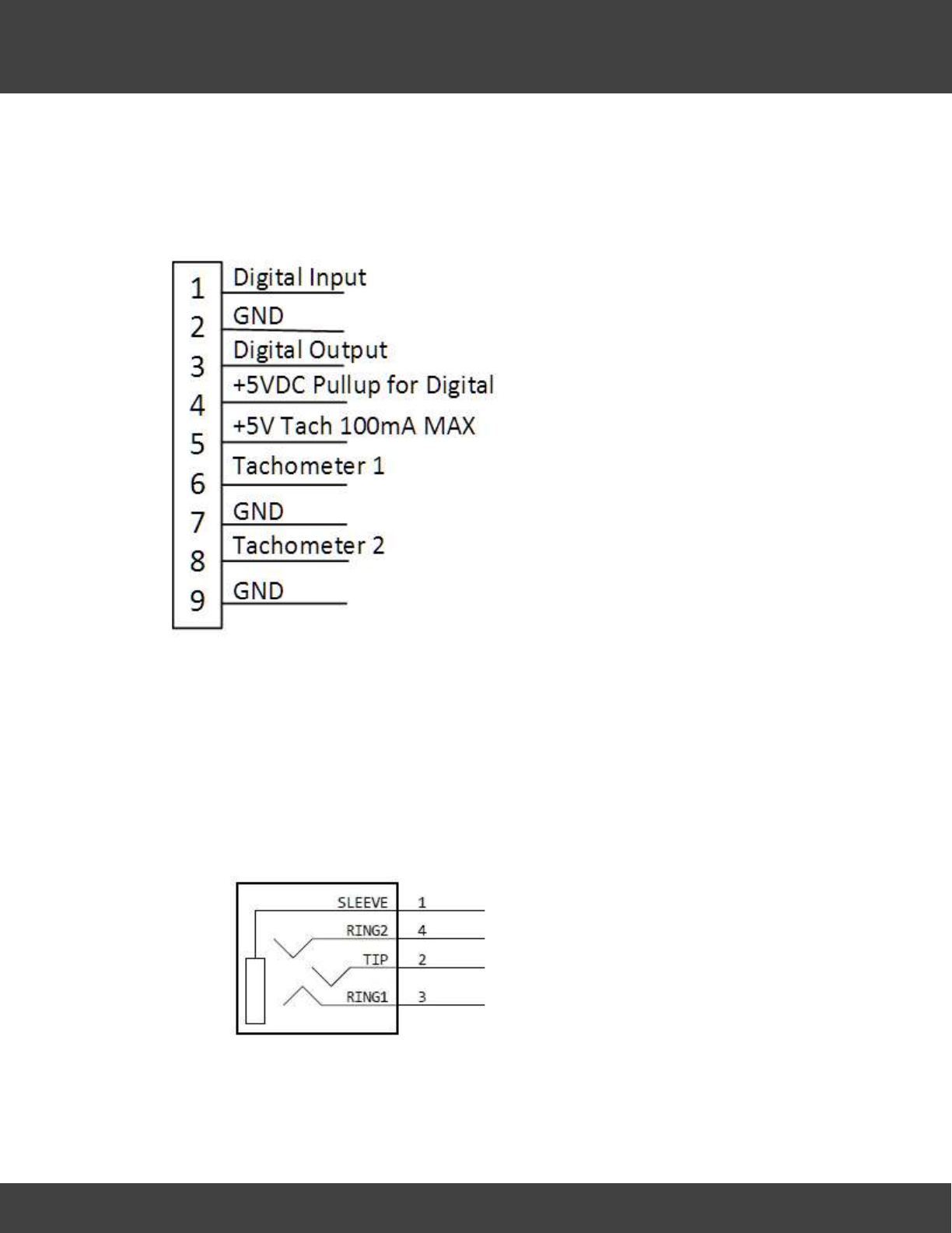
Tachometer Connector
A triaxial BNC breakout cable may be used on the tachometer connector. If used this way
the X connector is the digital output. The Y connector is the first tachometer. The Z
connector is the second tachometer. Tachometer channels support Low-Impedance Hall
Effect Magentics. Adaptive Threshold Input Voltage Level is +/- 30V, and the tachometers
will tolerate +/- 40V. The Digital Input and Output are 3.3V TTL logic levels, and will
tolerate 5V TTL logic levels.
Audio Input/Output
The audio Input/Output connector supports a headset typically used with an iPhone(R) 6.
46
ObserVIEW Help © 2017 Vibration Research Corporation
Hardware Description
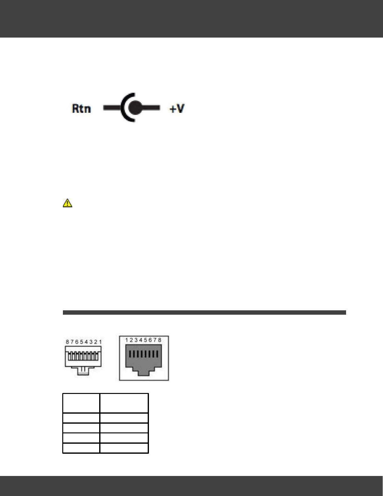
External AC Power Connector
The OBSERVR1000 is powered by using 18V 2.7A DC power adapter included in the package.
An optional DC power adapter is available from Vibration Research.
The included power adapter must be powered from 100-240VAC Nominal power outlet at
50/60Hz. The adapter draws less than 1A AC.
External Battery Connector
The OBSERVR1000 supports an optional external battery available from Vibration Research
Corporation.
CAUTION: Don’t use a battery not supplied by Vibration Research or an authorized
service provider.
GPS Connector
The GPS connector supports an optional GPS module available from Vibration Research
Corporation.
6.4 RJ45 Connections
The 10/100/1000 BASE-T ports are copper Twisted-Pair ports.
RJ45 Pin Number Allocation for Ethernet Port
Pin No Function
1 TxRx 1+
2 TxRx 1-
3 TxRx 2+
4 TxRx 2-
47
ObserVIEW Help © 2017 Vibration Research Corporation
Hardware Description
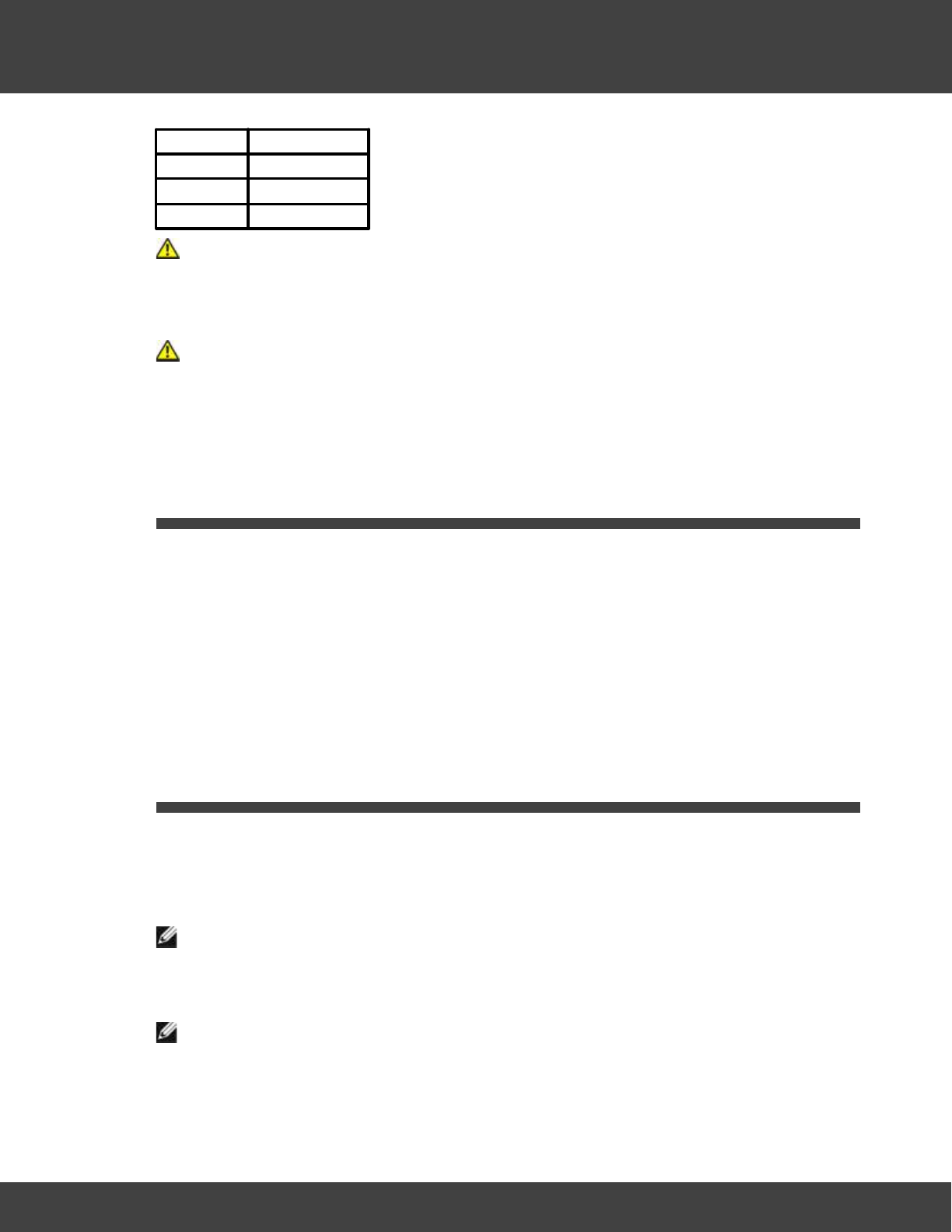
5 TxRx 3+
6 TxRx 3-
7 TxRx 4+
8 TxRx 4-
CAUTION Terminals provided on the unit shall be connected only to passive load
transducers or source transducers that apply no more than 10V to the circuit that
originates from the OBSERVR1000 (or other value that equates to not more than 33Vac
rms /46.7V peak or 70Vdc total on the circuit)
CAUTION Other than the IEC inlet for input power to the unit, terminals provided
on the rear of the unit shall be connected only to SELV / double insulated circuits of
other equipment.
6.5 Physical Dimensions
OBSERVR1000 dimensions
Without external battery
6.3" x 9.8" x 2.2" (160 x 250 x 56 mm)
With external battery
6.3" x 9.8" x 3.2" (160 x 250 x 81 mm)
6.6 Using The Battery
Battery Performance
The OBSERVR1000 battery is not user serviceable.
NOTE: Connect your battery using the AC adapter, to an electrical outlet, when you use
your OBSERVR1000 for the first time. For best results, operate the OBSERVR1000 with the AC
adapter until the battery is fully charged.
NOTE: Battery operating time (the time the battery can hold a charge) decreases over
time. Depending on how often the battery is used and the conditions under which it is used,
you may need to purchase a new battery during the life of your OBSERVR1000.

48
ObserVIEW Help © 2017 Vibration Research Corporation
Hardware Description
Battery operating time varies depending on usage.
CAUTION: Don’t attempt to replace the OBSERVR1000 battery yourself—you may
damage the battery, which could cause overheating, fire, and injury. The lithium-ion battery in
your OBSERVR1000 should be serviced or recycled by Vibration Research or an authorized
service provider, and must be recycled or disposed of separately from household waste.
Dispose of batteries according to your local environmental laws and guidelines.