Viconics Electronics VWG40 WIRELESS THERMOSTAT User Manual 028 6013 LIT VWG 40 SETUP E06
Viconics Electronics Inc. WIRELESS THERMOSTAT 028 6013 LIT VWG 40 SETUP E06
UserManual.wiki
>
Viconics Electronics
>
VWG40 User Manual
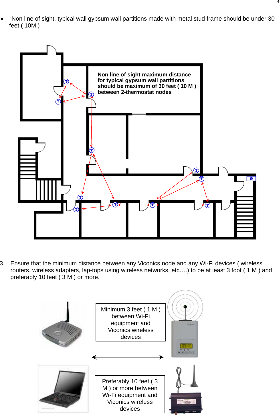
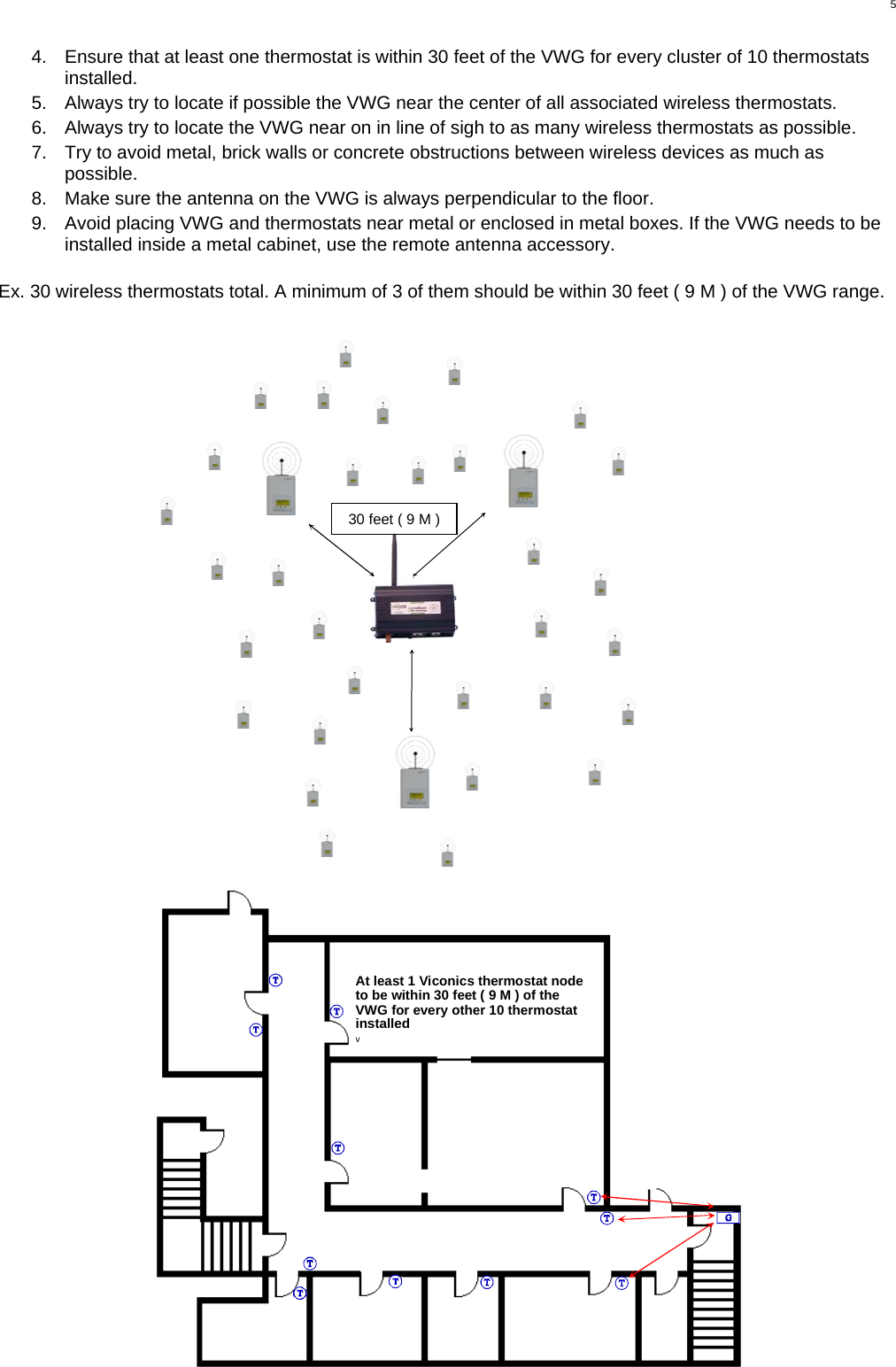
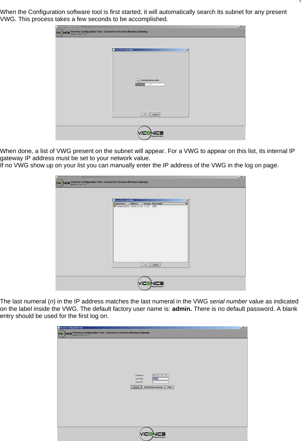
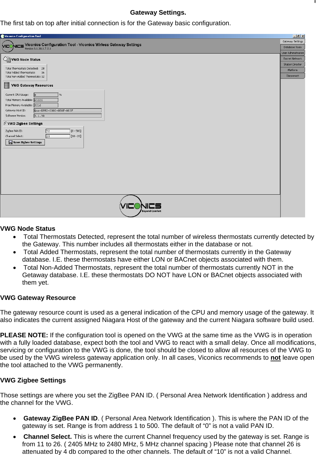
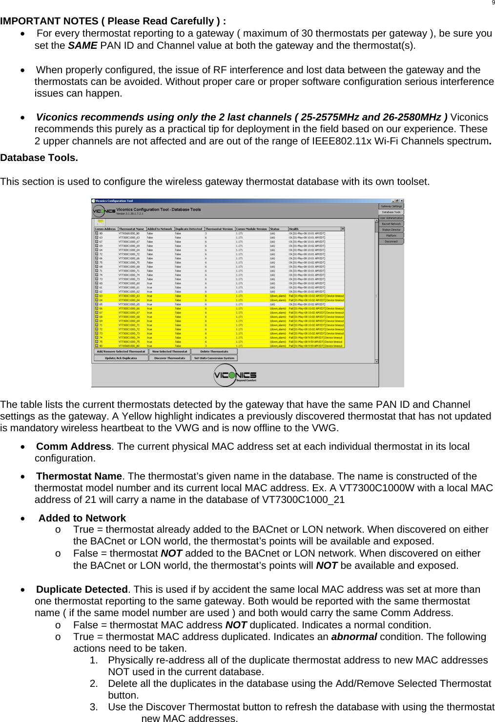
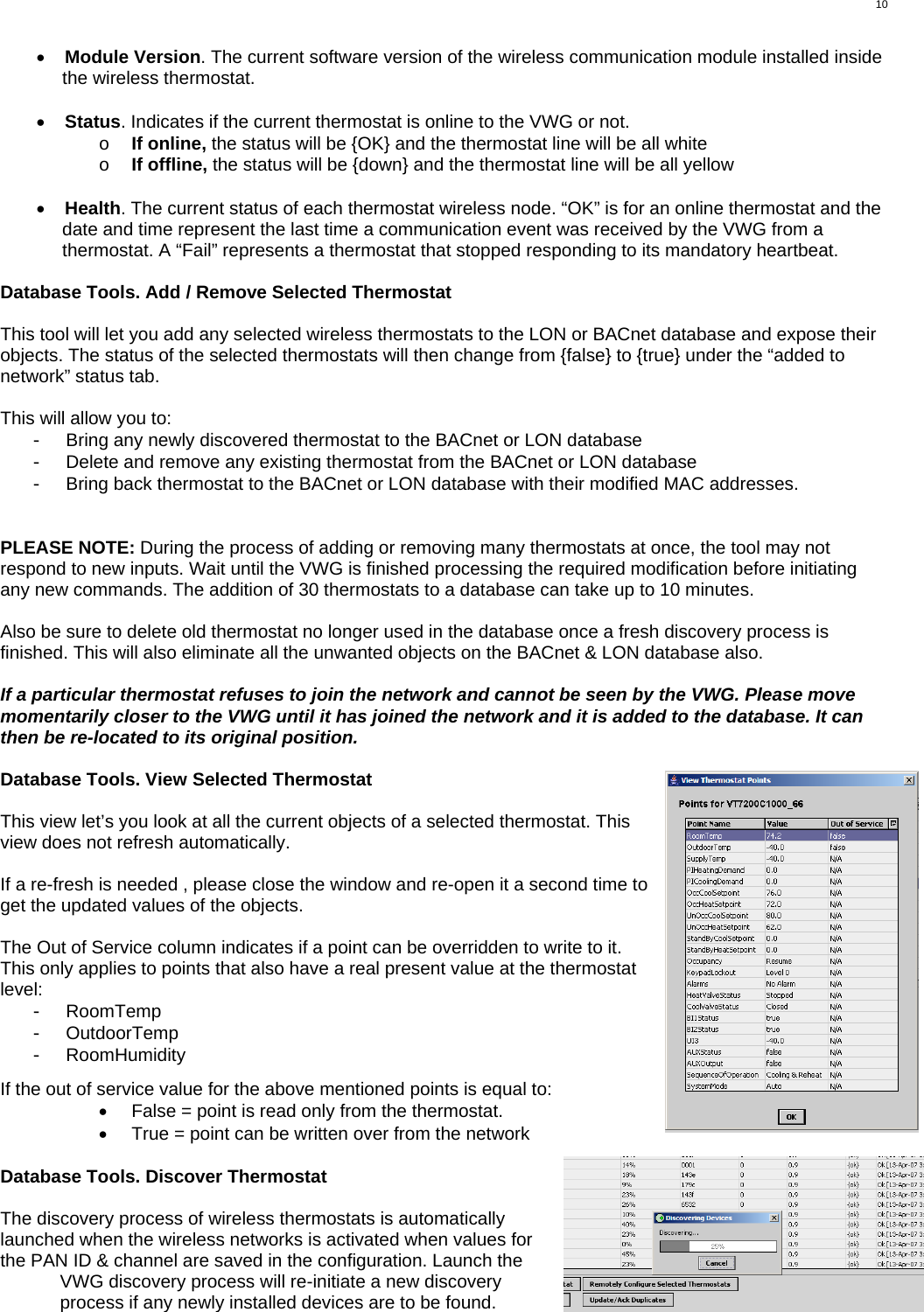
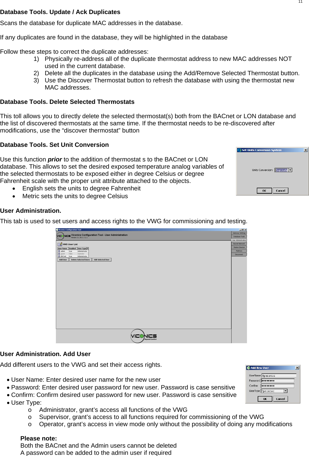
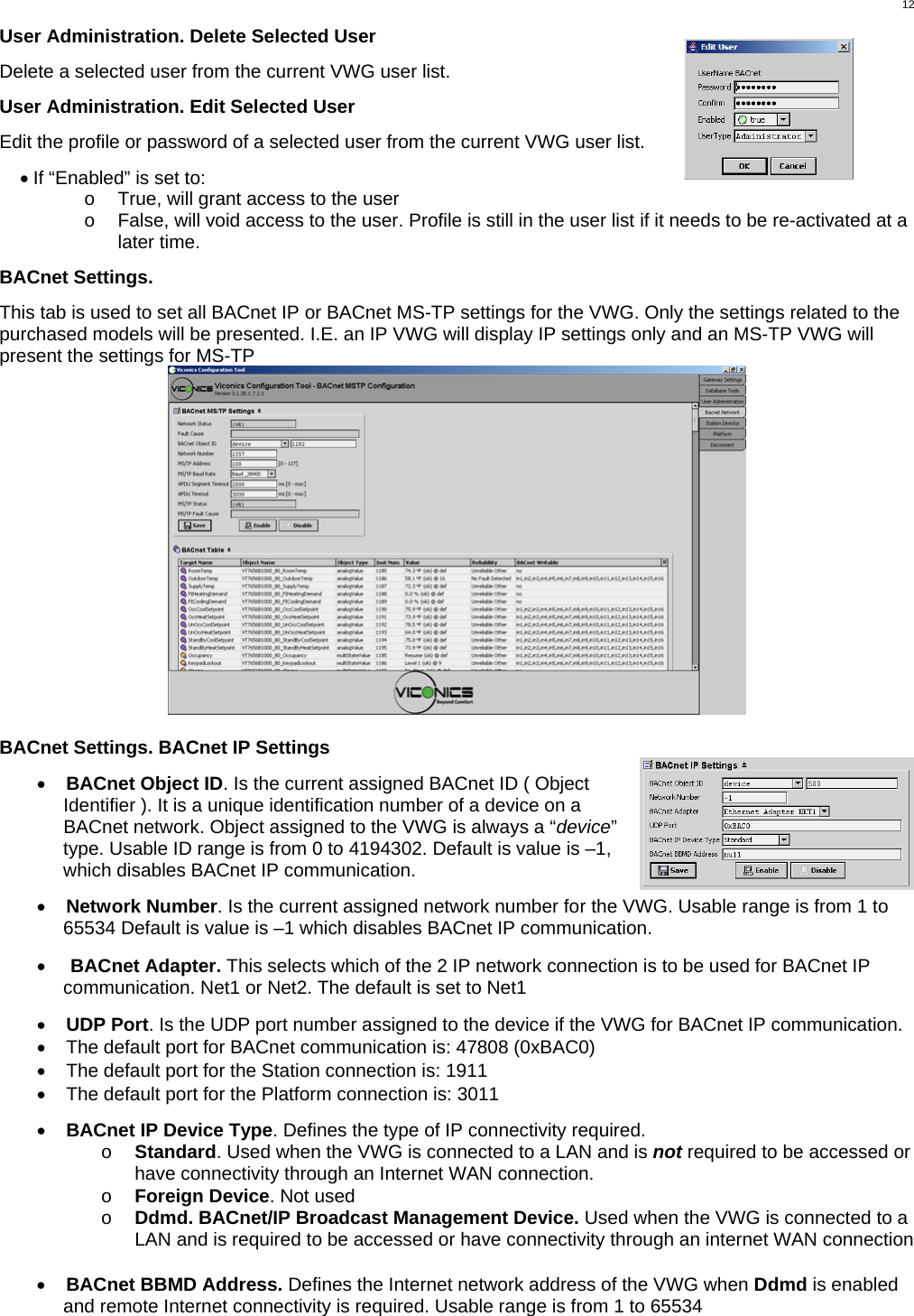
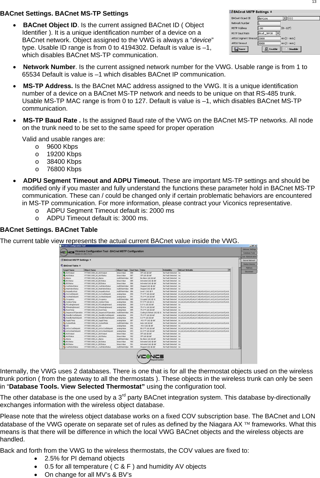
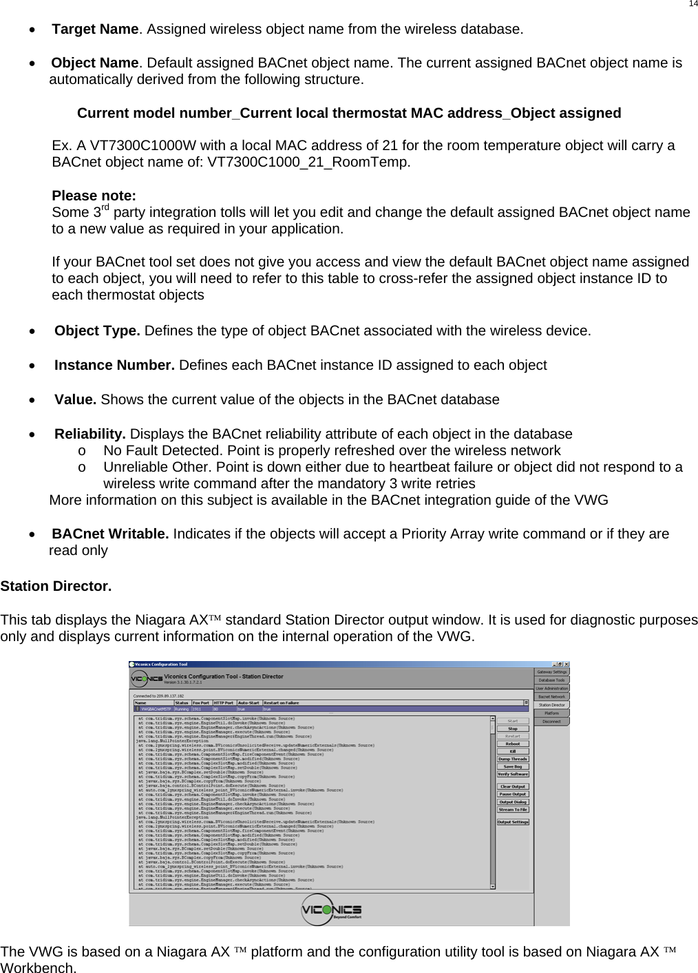
USERS MANUAL
Navigation menu
Upload a User Manual
Namespaces
Wiki Guide
HTML
PDF
Info
Views
User Manual
Discussion / Help
Navigation