Viconics Electronics VWG40 WIRELESS THERMOSTAT User Manual 028 6013 LIT VWG 40 SETUP E06
Viconics Electronics Inc. WIRELESS THERMOSTAT 028 6013 LIT VWG 40 SETUP E06
USERS MANUAL
VWG-40
Viconics Wireless Gateway
Design Consideration and Setup Guide
(Issue Date June 9, 2008 – 028-6013 E06)
Product overview
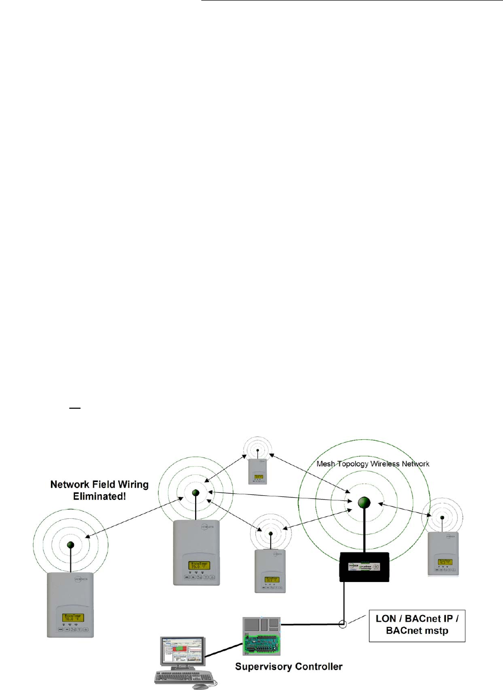
The VWG-40 and related wireless thermostats are targeted to retrofit applications where
the addition of communicating field bus wiring within the building space is prohibitive. The
Gateway and Communicating Thermostats with wireless field bus encourages the use of
existing wiring utilized by existing electronic thermostat type controls.
The VWG-40-XX-1000 when utilized in conjunction with the VT7xxxXxxxxW series wireless
thermostats will offer the integrator simple BACnet IP or BACnet MS/TP objects to integrate over standard
building automation systems using familiar integration toolsets.
A maximum of 30 wireless thermostats can be wirelessly attached to a single VWG
The following additional documentation is available on www.viconics.com
• Gateway BACnet integration guide (VWG-40-IP & VWG-40-MSTP), is available in document ITG-VWG-40-BAC-Exx
• Information on VWG hardware installation is available in document LIT-VWG-40-INSTALL-Exx
Part available
Part number Description
VWG-40-IP-1000 Viconics BACnet over IP wireless gateway. Includes:
- Supports up to 30 wireless thermostats
- Factory mounted wireless adapter
- 24 Vac panel mounted power supply
- Gateway mounted antenna
VWG-40-MSTP-1000 Viconics BACnet RS485 MS-TP wireless gateway. Includes:
- Supports up to 30 wireless thermostats
- Factory mounted wireless adapter
- 24 Vac panel mounted power supply
- Gateway mounted antenna
VWG-40-LON-1000
(Upcoming)
Viconics LON wireless gateway. Includes:
- Supports up to 30 wireless thermostats
- Factory mounted wireless adapter
- 24 Vac panel mounted power supply
- Gateway mounted antenna
VWG-APP Interface software for VWG configuration and set-up. Operates
under Windows XP ™. Uses a LAN crossover IP connection for
initial set-up.
VWG-RA Remote antenna for gateway when the gateway is installed inside a
metal cabinet or when remote antennal mounting is required by
physical installation
VWG-WA Replacement antenna for gateway mounted antenna setup
VWG-PS-DC 24 Vac to 15 Vdc panel mounted power supply for VWG
VWG-PS-AC 120 Vac to 15 Vdc power supply for VWG with cord
VWG-BB Replacement battery backup pack for the VWG

1
Trademarks
Niagara, Niagara AX is a registered trademarks of Tridium, Inc.
LON, LonWorks and LonTalk are registered trademarks of Echelon Corporation
BACnet is a registered trademark of ASHRAE
Disclaimers
NO WARRANTY. Viconics, Inc. ( herein after referred to as “Viconics” ) makes no warranty as to the accuracy
of or use of this technical documentation. Any use of the technical documentation or the information contained
therein is solely at the risk of the user.
Documentation may include technical or other inaccuracies or typographical errors. Viconics reserves the
right to make changes to this document without prior notice, and the reader should in all cases consult
Viconics to determine whether any such changes have been made. The information in this publication does
not represent a commitment on the part of Viconics.
Viconics shall not be liable for incidental or consequential damages resulting from the furnishing,
performance, or use of this material.
This guide contains links and references to third-party websites that are not under the control of Viconics, and
Viconics is not responsible for the content of any reference material or linked websites. If you access a third
party website mentioned in this guide, then you do so at your own risk. Viconics provides these links only as a
convenience, and the inclusion of the link does not imply that Viconics endorses or accepts any responsibility
for the content on those third-party sites.
Electronic controls are static sensitive devices. Discharge yourself properly before manipulation and
installing the Viconics wireless gateway.
All Viconics wireless gateways and related wireless thermostats are to be used only as operating controls.
Whenever a control failure could lead to personal injury and/or loss of property, it becomes the responsibility
of the user to add safety devices and/or alarm system to protect against such catastrophic failures.
All VT7000 series wireless thermostats and associated VWG (Viconics Wireless Gateway) have been
rigorously tested to ensure reliable operation in most building applications using the latest 2.4 Zigbee
technologies. Viconics cannot guarantee against potential network interference should additional wireless
systems be deployed sharing close proximity.
Best practices covered in this manual and all related Viconics VWG documents should be considered as a
guide to apply Viconics Wireless Network devices only. The instructions included in this manual are based
upon Viconics in house testing and should be referred to as a guide only.
Viconics Inc. may not be held liable for continued reliable, or robust operation of any and all wireless based
devices. Although Viconics has taken many precautions in assuring the robustness of the VT7000 series
wireless thermostat product line and associated network access point (VWG-40-XXXX-1000) Please note;
future application of additional wireless devices utilizing the same or similar channels and / or frequencies may
degrade performance of overall system and / or reliability.
Non-approved modifications or changes made to the VWG or wireless thermostats may void the FCC
compliance of the VWG and wireless thermostats.
THIS DEVICE COMPLIES WITH PART 15 OF THE FCC RULES. OPERATION IS SUBJECT TO THE
FOLLOWING TWO CONDITIONS: (1) THIS DEVICE MAY NOT CAUSE HARMFUL INTERFERENCE, AND
(2) THIS DEVICE MUST ACCEPT ANY INTERFERENCE RECEIVED, INCLUDING INTERFERENCE THAT
MAY CAUSE UNDESIRED OPERATION.
2
About Viconics Wireless Mesh Networks
The Viconics Wireless Gateway (VWG) and related wireless thermostat family (VT7xxxXxxxxW) networkable
devices operate using ZigBee/IEEE 802.15.4 physical layer for communication.
General characteristics of the wireless physical communication layer are:
• Uses a wireless physical layer of 2.4GHz with a data rates of 250 kbps
• Yields high throughput and low latency
• Automatic multiple topologies configuration: star, peer-to-peer, mesh
• Fully handshake protocol for transfer reliability
• Range: 30 feet / 10M typical (up to 100 feet / 30 M based on environment)
IEEE 802.15.4 along with ZigBee’s Network and Application Support Layer provide:
• Low cost installation deployment
• Ease of implementation
• Reliable data transfer
• Short range operation
• Very low power consumption
• Appropriate levels of security
The VWG acts as network coordinator device for the IEEE 802.15.4/ZigBee network used with the Viconics
wireless thermostats.
Many network specific features of the IEEE 802.15.4 standard are not covered in detail in this paper.
However, these are necessary for the efficient operation of a ZigBee network. These features of the network
physical layer include receiver energy detection, link quality indication and clear channel assessment. Both
contention-based and contention-free channel access methods are supported with a maximum packet size of
128 bytes, which includes a variable payload up to 104 bytes. Also employed are 64-bit IEEE and 16-bit short
addressing, supporting over 65,000 nodes per network. All those properties of the physical layer are used and
employed by the Viconics mesh network but are hidden to the installed / user for ease of configuration and
commissioning of the network database.
A maximum of 30 networkable thermostats can be supported by a single VWG. Database creation and
configuration is easily made using a Viconics software appliance that communicates with the VWG.
3
Basic Initial Design And Deployment Consideration
Proper design considerations need to be addressed prior to any installation of a Viconics Wireless Gateway
(VWG) and related wireless thermostats.
1. To properly avoid network interference with 802.11 Wi-Fi devices in the 2.4GHz spectrum range,
Viconics recommends the use of 802.15.4 channels 25 and 26 only. 802.11 Wi-Fi transmissions
overlap and may interfere with other channel selection allowed by 802.15.4 ( Channels 11 to 24 )
2. Maximum distance between each node ( thermostat ) should be:
• Clear line of sight between 2 nodes should be under 100 feet ( 30 M )
Maximum 100 feet ( 30 M )
between 2 thermostat nodes
Open clear line of sight distance between
2 nodes should be a maximum of
100 feet ( 30 M )

4
• Non line of sight, typical wall gypsum wall partitions made with metal stud frame should be under 30
feet ( 10M )
3. Ensure that the minimum distance between any Viconics node and any Wi-Fi devices ( wireless
routers, wireless adapters, lap-tops using wireless networks, etc….) to be at least 3 foot ( 1 M ) and
preferably 10 feet ( 3 M ) or more.
Maximum 30 feet ( 10 M )
between 2-thermostat nodes
Minimum 3 feet ( 1 M )
between Wi-Fi
equipment and
Viconics wireless
devices
Preferably 10 feet ( 3
M ) or more between
Wi-Fi equipment and
Viconics wireless
devices
Non line of sight maximum distance
for typical gypsum wall partitions
should be maximum of 30 feet ( 10 M )
between 2-thermostat nodes
5
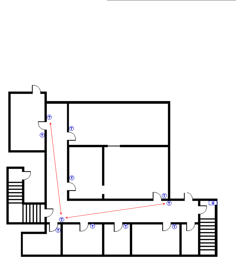
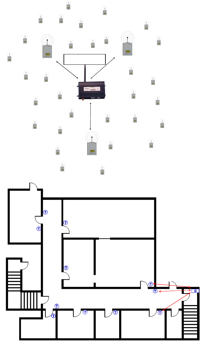
4. Ensure that at least one thermostat is within 30 feet of the VWG for every cluster of 10 thermostats
installed.
5. Always try to locate if possible the VWG near the center of all associated wireless thermostats.
6. Always try to locate the VWG near on in line of sigh to as many wireless thermostats as possible.
7. Try to avoid metal, brick walls or concrete obstructions between wireless devices as much as
possible.
8. Make sure the antenna on the VWG is always perpendicular to the floor.
9. Avoid placing VWG and thermostats near metal or enclosed in metal boxes. If the VWG needs to be
installed inside a metal cabinet, use the remote antenna accessory.
Ex. 30 wireless thermostats total. A minimum of 3 of them should be within 30 feet ( 9 M ) of the VWG range.
30 feet
(
9 M
)
At least 1 Viconics thermostat node
to be within 30 feet ( 9 M ) of the
VWG for every other 10 thermostat
installed
v

6
Gateway Configuration
Initial Connection
Install the software on the CD provided with the VWG. The setup will guide you through the necessary
installation steps. The minimum system requirements for installation are:
• An Ethernet adapter with TCP/IP support
• A WEB browser installed.
IMPORTANT NOTE: Unless updated ( Jar files ), the tool used to service or commission the VWG should
always be the one originally supplier with the VWG
An Ethernet TCP/IP connection to the VWG is required for commissioning. For this initial Ethernet connection,
you can use either:
• A “crossover” cable connected directly between your PC and the VWG
• A normal LAN connection, meaning that both your PC and the VWG are physically connected to the
same Ethernet hub or switch.
As shipped from the factory, a VWG contains only the bare minimum software to run the wireless gateway
application. The gateway does not contain a Java Virtual Machine runtime environment, a WEB UI interface
or any additional software modules. A VWG does include a core Niagara software load and a Tridium
certificate. Using the supplied software appliance, you must connect to the VWG for initial configuration.
Some important related tasks including setting the VWG IP network address and related wireless database
setup can only be accomplished using this software appliance.
Initial IP address When shipped, a new VWG is pre-configured with an IP address in the range of:
192.168.1.12n (primary “LAN1” port, the “LAN2” port is disabled) where the last numeral (n) in the IP address
matches the last numeral in the VWG serial number. The VWG serial number can be found directly on the
label inside the VWG. In all cases, the default subnet mask is: 255.255.255.0 .
Two areas of preparation are required before proceeding with the configuration. Provide power and
connectivity. After you complete the commissioning process described in this document, you can mount and
wire the VWG controller at the job site, making permanent mounting and wiring connections.
To prepare a new VWG for commissioning, do the following steps:
1. If not already installed, install the supplied Viconics Configuration Software on your local host PC
machine.
2. Attach one end of a standard category-5 Ethernet unshielded twisted pair (UTP) patch cable to the
RJ-45 Ethernet connector on the VWG.
3. Attach the other end of the patch cable to a network port or directly to an Ethernet hub.
4. Power up the VWG.
5. Record you PC’s current IP settings, then re-assign your PC’s IP address for its Ethernet LAN
adapter (if necessary, refer to Windows online Help for information about configuring TCP/IP
settings).
6. For this initial connection to a factory-shipped VWG, configure your PC to use an IP address in the
same subnet as the VWG, as well as a matching subnet mask.
7. Set the IP address in the range: 192.168.1.1 to 192.168.1.254 with a subnet mask of: 255.255.255.0
Note: Do not assign your PC the identical IP address as the VWG factory-assigned IP address.
8. From your PC, start the Configuration software. ( under Start\Viconics Configuration Tool Setup 1.X.X
7
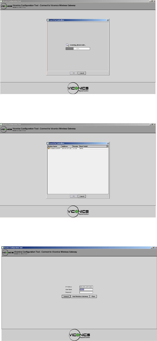
When the Configuration software tool is first started, it will automatically search its subnet for any present
VWG. This process takes a few seconds to be accomplished.
When done, a list of VWG present on the subnet will appear. For a VWG to appear on this list, its internal IP
gateway IP address must be set to your network value.
If no VWG show up on your list you can manually enter the IP address of the VWG in the log on page.
The last numeral (n) in the IP address matches the last numeral in the VWG serial number value as indicated
on the label inside the VWG. The default factory user name is: admin. There is no default password. A blank
entry should be used for the first log on.
8
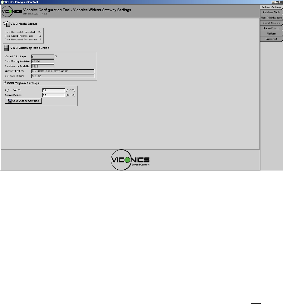
Gateway Settings.
The first tab on top after initial connection is for the Gateway basic configuration.
VWG Node Status
• Total Thermostats Detected, represent the total number of wireless thermostats currently detected by
the Gateway. This number includes all thermostats either in the database or not.
• Total Added Thermostats, represent the total number of thermostats currently in the Gateway
database. I.E. these thermostats have either LON or BACnet objects associated with them.
• Total Non-Added Thermostats, represent the total number of thermostats currently NOT in the
Getaway database. I.E. these thermostats DO NOT have LON or BACnet objects associated with
them yet.
VWG Gateway Resource
The gateway resource count is used as a general indication of the CPU and memory usage of the gateway. It
also indicates the current assigned Niagara Host of the gateway and the current Niagara software build used.
PLEASE NOTE: If the configuration tool is opened on the VWG at the same time as the VWG is in operation
with a fully loaded database, expect both the tool and VWG to react with a small delay. Once all modifications,
servicing or configuration to the VWG is done, the tool should be closed to allow all resources of the VWG to
be used by the VWG wireless gateway application only. In all cases, Viconics recommends to not leave open
the tool attached to the VWG permanently.
VWG Zigbee Settings
Those settings are where you set the ZigBee PAN ID. ( Personal Area Network Identification ) address and
the channel for the VWG.
• Gateway ZigBee PAN ID. ( Personal Area Network Identification ). This is where the PAN ID of the
gateway is set. Range is from address 1 to 500. The default of “0” is not a valid PAN ID.
• Channel Select. This is where the current Channel frequency used by the gateway is set. Range is
from 11 to 26. ( 2405 MHz to 2480 MHz, 5 MHz channel spacing ) Please note that channel 26 is
attenuated by 4 db compared to the other channels. The default of “10” is not a valid Channel.
9
IMPORTANT NOTES ( Please Read Carefully ) :
• For every thermostat reporting to a gateway ( maximum of 30 thermostats per gateway ), be sure you
set the SAME PAN ID and Channel value at both the gateway and the thermostat(s).
• When properly configured, the issue of RF interference and lost data between the gateway and the
thermostats can be avoided. Without proper care or proper software configuration serious interference
issues can happen.
• Viconics recommends using only the 2 last channels ( 25-2575MHz and 26-2580MHz ) Viconics
recommends this purely as a practical tip for deployment in the field based on our experience. These
2 upper channels are not affected and are out of the range of IEEE802.11x Wi-Fi Channels spectrum.
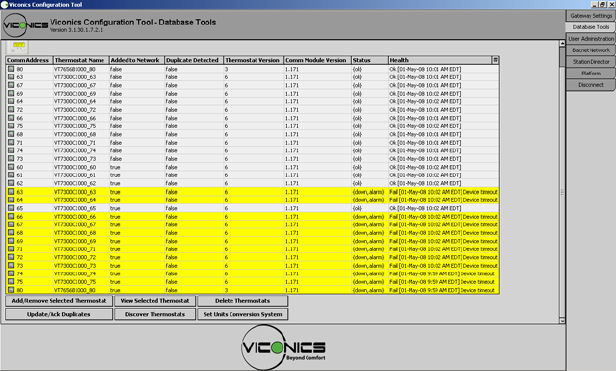
Database Tools.
This section is used to configure the wireless gateway thermostat database with its own toolset.
The table lists the current thermostats detected by the gateway that have the same PAN ID and Channel
settings as the gateway. A Yellow highlight indicates a previously discovered thermostat that has not updated
is mandatory wireless heartbeat to the VWG and is now offline to the VWG.
• Comm Address. The current physical MAC address set at each individual thermostat in its local
configuration.
• Thermostat Name. The thermostat’s given name in the database. The name is constructed of the
thermostat model number and its current local MAC address. Ex. A VT7300C1000W with a local MAC
address of 21 will carry a name in the database of VT7300C1000_21
• Added to Network
o True = thermostat already added to the BACnet or LON network. When discovered on either
the BACnet or LON world, the thermostat’s points will be available and exposed.
o False = thermostat NOT added to the BACnet or LON network. When discovered on either
the BACnet or LON world, the thermostat’s points will NOT be available and exposed.
• Duplicate Detected. This is used if by accident the same local MAC address was set at more than
one thermostat reporting to the same gateway. Both would be reported with the same thermostat
name ( if the same model number are used ) and both would carry the same Comm Address.
o False = thermostat MAC address NOT duplicated. Indicates a normal condition.
o True = thermostat MAC address duplicated. Indicates an abnormal condition. The following
actions need to be taken.
1. Physically re-address all of the duplicate thermostat address to new MAC addresses
NOT used in the current database.
2. Delete all the duplicates in the database using the Add/Remove Selected Thermostat
button.
3. Use the Discover Thermostat button to refresh the database with using the thermostat
new MAC addresses.
10
• Module Version. The current software version of the wireless communication module installed inside
the wireless thermostat.
• Status. Indicates if the current thermostat is online to the VWG or not.
o If online, the status will be {OK} and the thermostat line will be all white
o If offline, the status will be {down} and the thermostat line will be all yellow
• Health. The current status of each thermostat wireless node. “OK” is for an online thermostat and the
date and time represent the last time a communication event was received by the VWG from a
thermostat. A “Fail” represents a thermostat that stopped responding to its mandatory heartbeat.
Database Tools. Add / Remove Selected Thermostat
This tool will let you add any selected wireless thermostats to the LON or BACnet database and expose their
objects. The status of the selected thermostats will then change from {false} to {true} under the “added to
network” status tab.
This will allow you to:
- Bring any newly discovered thermostat to the BACnet or LON database
- Delete and remove any existing thermostat from the BACnet or LON database
- Bring back thermostat to the BACnet or LON database with their modified MAC addresses.
PLEASE NOTE: During the process of adding or removing many thermostats at once, the tool may not
respond to new inputs. Wait until the VWG is finished processing the required modification before initiating
any new commands. The addition of 30 thermostats to a database can take up to 10 minutes.
Also be sure to delete old thermostat no longer used in the database once a fresh discovery process is
finished. This will also eliminate all the unwanted objects on the BACnet & LON database also.
If a particular thermostat refuses to join the network and cannot be seen by the VWG. Please move
momentarily closer to the VWG until it has joined the network and it is added to the database. It can
then be re-located to its original position.
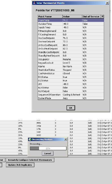
Database Tools. View Selected Thermostat
This view let’s you look at all the current objects of a selected thermostat. This
view does not refresh automatically.
If a re-fresh is needed , please close the window and re-open it a second time to
get the updated values of the objects.
The Out of Service column indicates if a point can be overridden to write to it.
This only applies to points that also have a real present value at the thermostat
level:
- RoomTemp
- OutdoorTemp
- RoomHumidity
If the out of service value for the above mentioned points is equal to:
• False = point is read only from the thermostat.
• True = point can be written over from the network
Database Tools. Discover Thermostat
The discovery process of wireless thermostats is automatically
launched when the wireless networks is activated when values for
the PAN ID & channel are saved in the configuration. Launch the
VWG discovery process will re-initiate a new discovery
process if any newly installed devices are to be found.
11
Database Tools. Update / Ack Duplicates
Scans the database for duplicate MAC addresses in the database.
If any duplicates are found in the database, they will be highlighted in the database
Follow these steps to correct the duplicate addresses:
1) Physically re-address all of the duplicate thermostat address to new MAC addresses NOT
used in the current database.
2) Delete all the duplicates in the database using the Add/Remove Selected Thermostat button.
3) Use the Discover Thermostat button to refresh the database with using the thermostat new
MAC addresses.
Database Tools. Delete Selected Thermostats
This toll allows you to directly delete the selected thermostat(s) both from the BACnet or LON database and
the list of discovered thermostats at the same time. If the thermostat needs to be re-discovered after
modifications, use the “discover thermostat” button
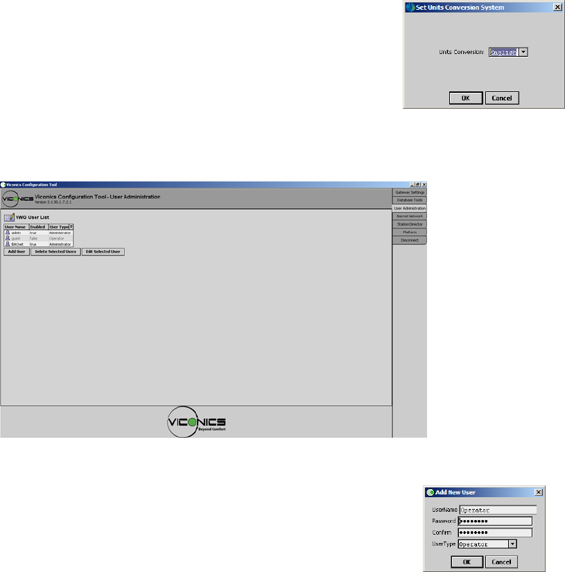
Database Tools. Set Unit Conversion
Use this function prior to the addition of thermostat s to the BACnet or LON
database. This allows to set the desired exposed temperature analog variables of
the selected thermostats to be exposed either in degree Celsius or degree
Fahrenheit scale with the proper unit attribute attached to the objects.
• English sets the units to degree Fahrenheit
• Metric sets the units to degree Celsius
User Administration.
This tab is used to set users and access rights to the VWG for commissioning and testing.
User Administration. Add User
Add different users to the VWG and set their access rights.
• User Name: Enter desired user name for the new user
• Password: Enter desired user password for new user. Password is case sensitive
• Confirm: Confirm desired user password for new user. Password is case sensitive
• User Type:
o Administrator, grant’s access all functions of the VWG
o Supervisor, grant’s access to all functions required for commissioning of the VWG
o Operator, grant’s access in view mode only without the possibility of doing any modifications
Please note:
Both the BACnet and the Admin users cannot be deleted
A password can be added to the admin user if required
12
User Administration. Delete Selected User
Delete a selected user from the current VWG user list.
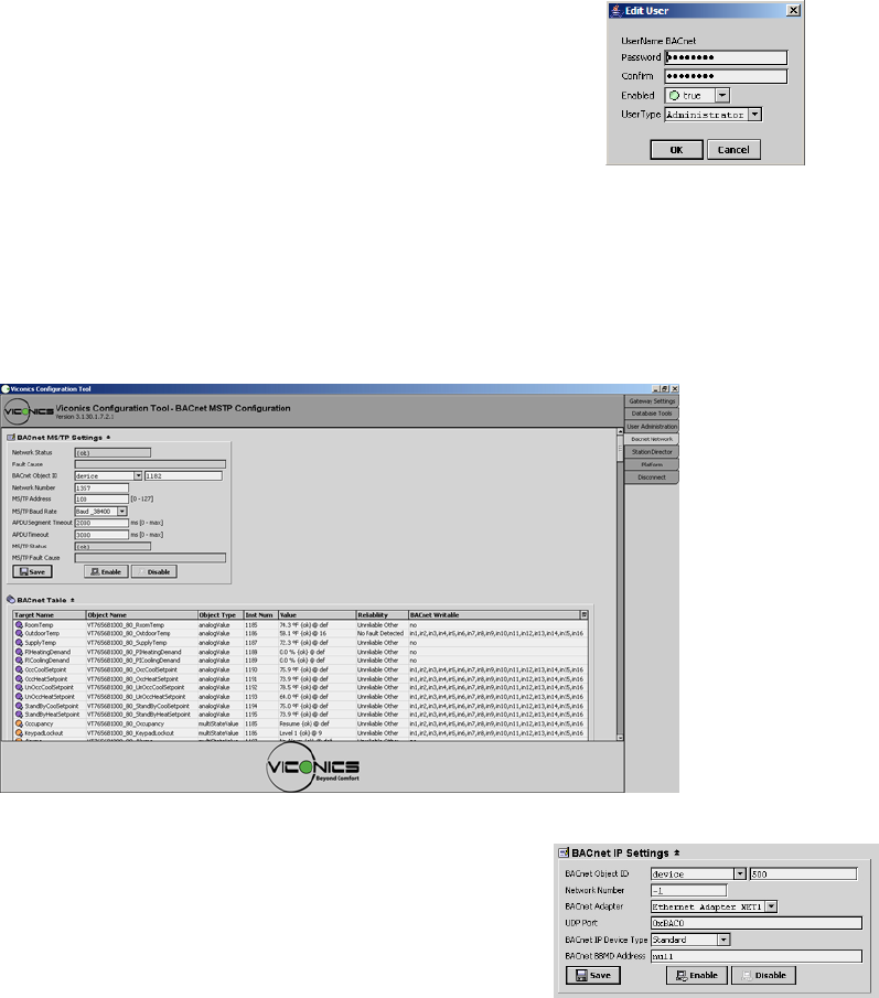
User Administration. Edit Selected User
Edit the profile or password of a selected user from the current VWG user list.
• If “Enabled” is set to:
o True, will grant access to the user
o False, will void access to the user. Profile is still in the user list if it needs to be re-activated at a
later time.
BACnet Settings.
This tab is used to set all BACnet IP or BACnet MS-TP settings for the VWG. Only the settings related to the
purchased models will be presented. I.E. an IP VWG will display IP settings only and an MS-TP VWG will
present the settings for MS-TP
BACnet Settings. BACnet IP Settings
• BACnet Object ID. Is the current assigned BACnet ID ( Object
Identifier ). It is a unique identification number of a device on a
BACnet network. Object assigned to the VWG is always a “device”
type. Usable ID range is from 0 to 4194302. Default is value is –1,
which disables BACnet IP communication.
• Network Number. Is the current assigned network number for the VWG. Usable range is from 1 to
65534 Default is value is –1 which disables BACnet IP communication.
• BACnet Adapter. This selects which of the 2 IP network connection is to be used for BACnet IP
communication. Net1 or Net2. The default is set to Net1
• UDP Port. Is the UDP port number assigned to the device if the VWG for BACnet IP communication.
• The default port for BACnet communication is: 47808 (0xBAC0)
• The default port for the Station connection is: 1911
• The default port for the Platform connection is: 3011
• BACnet IP Device Type. Defines the type of IP connectivity required.
o Standard. Used when the VWG is connected to a LAN and is not required to be accessed or
have connectivity through an Internet WAN connection.
o Foreign Device. Not used
o Ddmd. BACnet/IP Broadcast Management Device. Used when the VWG is connected to a
LAN and is required to be accessed or have connectivity through an internet WAN connection
• BACnet BBMD Address. Defines the Internet network address of the VWG when Ddmd is enabled
and remote Internet connectivity is required. Usable range is from 1 to 65534
13
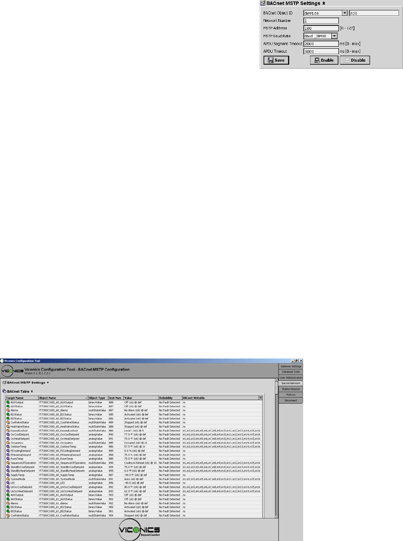
BACnet Settings. BACnet MS-TP Settings
• BACnet Object ID. Is the current assigned BACnet ID ( Object
Identifier ). It is a unique identification number of a device on a
BACnet network. Object assigned to the VWG is always a “device”
type. Usable ID range is from 0 to 4194302. Default is value is –1,
which disables BACnet MS-TP communication.
• Network Number. Is the current assigned network number for the VWG. Usable range is from 1 to
65534 Default is value is –1 which disables BACnet IP communication.
• MS-TP Address. Is the BACnet MAC address assigned to the VWG. It is a unique identification
number of a device on a BACnet MS-TP network and needs to be unique on that RS-485 trunk.
Usable MS-TP MAC range is from 0 to 127. Default is value is –1, which disables BACnet MS-TP
communication.
• MS-TP Baud Rate . Is the assigned Baud rate of the VWG on the BACnet MS-TP networks. All node
on the trunk need to be set to the same speed for proper operation
Valid and usable ranges are:
o 9600 Kbps
o 19200 Kbps
o 38400 Kbps
o 76800 Kbps
• ADPU Segment Timeout and ADPU Timeout. These are important MS-TP settings and should be
modified only if you master and fully understand the functions these parameter hold in BACnet MS-TP
communication. These can / could be changed only if certain problematic behaviors are encountered
in MS-TP communication. For more information, please contract your Viconics representative.
o ADPU Segment Timeout default is: 2000 ms
o ADPU Timeout default is: 3000 ms.
BACnet Settings. BACnet Table
The current table view represents the actual current BACnet value inside the VWG.
Internally, the VWG uses 2 databases. There is one that is for all the thermostat objects used on the wireless
trunk portion ( from the gateway to all the thermostats ). These objects in the wireless trunk can only be seen
in “Database Tools. View Selected Thermostat” using the configuration tool.
The other database is the one used by a 3rd party BACnet integration system. This database by-directionally
exchanges information with the wireless object database.
Please note that the wireless object database works on a fixed COV subscription base. The BACnet and LON
database of the VWG operate on separate set of rules as defined by the Niagara AX ™ frameworks. What this
means is that there will be difference in which the local VWG BACnet objects and the wireless objects are
handled.
Back and forth from the VWG to the wireless thermostats, the COV values are fixed to:
• 2.5% for PI demand objects
• 0.5 for all temperature ( C & F ) and humidity AV objects
• On change for all MV’s & BV’s
14
• Target Name. Assigned wireless object name from the wireless database.
• Object Name. Default assigned BACnet object name. The current assigned BACnet object name is
automatically derived from the following structure.
Current model number_Current local thermostat MAC address_Object assigned
Ex. A VT7300C1000W with a local MAC address of 21 for the room temperature object will carry a
BACnet object name of: VT7300C1000_21_RoomTemp.
Please note:
Some 3rd party integration tolls will let you edit and change the default assigned BACnet object name
to a new value as required in your application.
If your BACnet tool set does not give you access and view the default BACnet object name assigned
to each object, you will need to refer to this table to cross-refer the assigned object instance ID to
each thermostat objects
• Object Type. Defines the type of object BACnet associated with the wireless device.
• Instance Number. Defines each BACnet instance ID assigned to each object
• Value. Shows the current value of the objects in the BACnet database
• Reliability. Displays the BACnet reliability attribute of each object in the database
o No Fault Detected. Point is properly refreshed over the wireless network
o Unreliable Other. Point is down either due to heartbeat failure or object did not respond to a
wireless write command after the mandatory 3 write retries
More information on this subject is available in the BACnet integration guide of the VWG
• BACnet Writable. Indicates if the objects will accept a Priority Array write command or if they are
read only
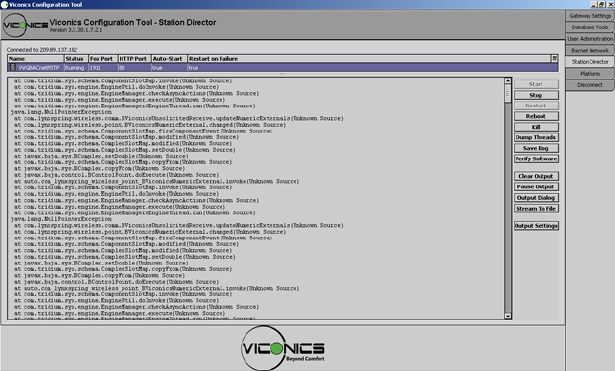
Station Director.
This tab displays the Niagara AX™ standard Station Director output window. It is used for diagnostic purposes
only and displays current information on the internal operation of the VWG.
The VWG is based on a Niagara AX ™ platform and the configuration utility tool is based on Niagara AX ™
Workbench.
15
The two start settings for the station are as follows:
• Auto-start ( Leave box checked )
Specifies whether the AX station starts following a platform startup. This means following a host reboot,
perhaps as a result of a power cycle, but possibly from a platform reboot command.
• Restart on Failure ( Leave box checked )
Specifies whether the platform restarts the station if the station’s process exits with a nonzero return code
(e.g., engine watchdog had killed the station because of a “deadlock” condition).
Note: Be careful about using station controls, and understand the difference between them before using them.
• Start
Enabled only if the station has an “Idle” or “Failed” status in the installed stations area. When pressed, that
host’s platform daemon immediately starts that station. Text in the station output is cleared, and output
messages begin with the new startup of that station.
• Stop
Enabled only if the station has a “Running” status in the installed stations area. When pressed, a popup
confirmation appears. If you confirm, the host’s platform daemon shuts the station down gracefully (saving its
configuration to its config.bog file, and potentially saving history data).
• Restart, Not available or used
• Reboot
Always enabled. When pressed, a popup confirmation dialog appears. If you confirm, the selected host is
rebooted. This is considered a drastic action.
• Kill
Enabled only if the station has a status of “Starting”, “Stopping”, or “Running” in the installed stations area.
When pressed, a popup confirmation dialog appears. If you confirm, the host’s platform daemon terminates
the station process immediately. Note: Always use Stop instead of Kill, unless unavailable (stuck for a long
time as either “Starting” or “Stopping”). Unlike a station stop, a station kill does not cause the station to save
its config.bog, nor does it update the station output area.
• Dump Threads
Enabled only if the station has a “Running” status in the installed stations area. When pressed, the host’s
platform daemon has the station send a VM thread dump to its station output.
• Save Bog
Enabled only if the station has a “Running” status in the installed stations area. When pressed, the host’s
platform daemon has the station locally save its configuration to config.bog.
• Verify Software
Enabled regardless of station status. When pressed, Workbench parses the station’s config. bog file and the
host’s platform.bog file, looking for module references. Workbench then checks to see if those modules are
installed. Any missing modules are listed in a popup dialog and if available in your Workbench installation, the
dialog offers to install the missing modules in the remote host.
• Clear Output
Enabled regardless of station status. When pressed, all text in the station output area is cleared. Note: Data in
the station output area is fetched from a memory buffer in the platform daemon. Clearing the output does not
actually clear the daemon’s buffer. Therefore, if you change the selection away from, and then back to the
station, it re-fetches all buffered data.
• Pause Output
Enabled only if the station has a “Running” status in the installed stations area. When pressed, the button
toggles to “Load Output”, and the next press back to “Pause Output” (and so on). During a paused output,
text remains frozen in the station output area. This is useful when the station is rapidly writing output. When
you press Load Output, text in the station output area is reloaded with the station’s buffered output, and
output remains updating in real time.
16
• Output Dialog
Enabled regardless of station status. When pressed, this produces a separate “non-modal” output window
displaying the same output text as in the Station Director’s station output area. Included are buttons to Dump
Threads, Pause Output, Clear Output, and Close the window.
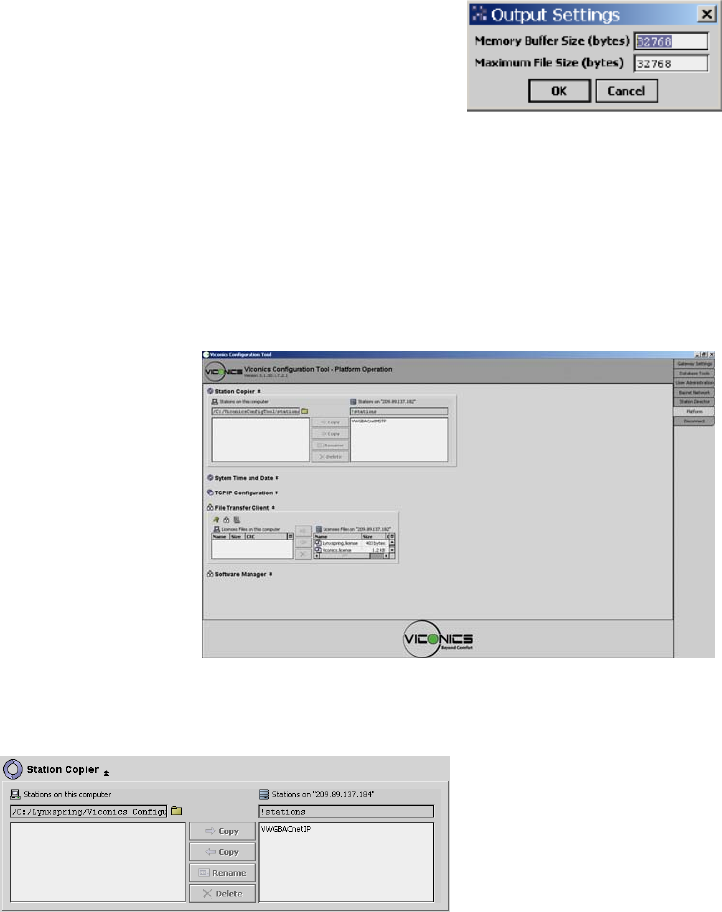
• Output settings
For the currently selected station in the Station Director, the Output Settings
button produces a dialog in which you specify how the platform daemon
buffers the output from that station.
Output Settings dialog
The two available settings are in bytes, and are:
• Memory Buffer Size
Size of the memory buffer for the station output. If the station creates more output that the size of
the memory buffer, the oldest output is lost.
• Maximum File Size
When the station stops, its output buffer is written to a console.txt file. This setting defines
the maximum size of that file.
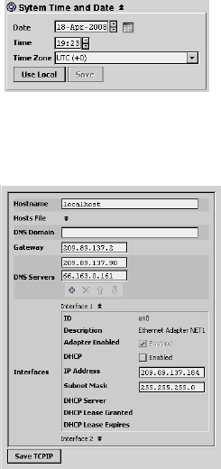
Platform.
This tab sets up different function of the VWG
• Station Copier
• System Date and Time
• TCP/IP Configuration
• File Transfer Client
• Software Manager
• Station Copier
The Station Copier is only used to install a new version of the VWG station when released by Viconics.
The important functions are:
− Copy from left to right to install a new VWG station from a local drive to the gateway.
− Copy from right to left save the current VWG station in the gateway to backup to a local drive.
− Use the Rename button to rename the VWG station name
− Use the delete button to delete a station that is no longer in use (older version on the gateway)
IMPORTANT NOTES:
Unless updated ( Jar files ), the tool used to service or commission the VWG should always be the one
originally supplier with the VWG.
When you database is fully up and all your devices have been added, it is recommended to do a backup of
your station for references and safety.
17
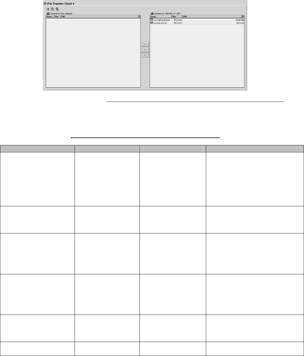
• Station Date and Time
This is used to set the local time at the VWG. This information practical in the
Database Tool view when viewing the health status and last time a thermostat
was online and communicating to the VWG
Use local will set the VWG time to the local time currently in the computer where the toll resides. Press the
“Save” button to confirm the changes.
• TCP/IP Configuration
Hostname. Is the local hostname exposed on the network. Please do not change
and leave to “Localhost”
DNS Domain. The TCP/IP Domain Name System (DNS) domain this host
belongs to. Only if DNS is used.
Gateway. The IP address for the device that forwards packets to other networks
or subnets.
DNS Servers. The IP address for one or more DNS servers, each of which can
automate associations between hostnames and IP addresses. Included are icon-
buttons to Add (to enter IP address of server), delete and move Up/Down (to set
the DNS search order).
• Interface 1. Set’s the local device IP settings for NET1
• Interface 2, Set’s the local device IP settings for NET2
The interface selected for BACnet IP communication is made at the “BACnet Network” tab under BACnet IP
Settings. The default connection used is NET1
Selectable fields are as follows:
ID. A read-only OS identifier for the hardware interface).
Description. A read-only text string such as “Ethernet Adapter”.
Adapter Enabled. Read-only checkbox that indicates whether the Ethernet port is usable.
DHCP. A checkbox to specify DHCP (Dynamic Host Configuration Protocol) instead of static IP
addressing. Successful use requires a DHCP server installed on your network. If enabled, other interface
fields such as IP Address and Subnet Mask become read-only, as the DHCP server assigns these after the
platform reboots.
Note: In general (for stability), static IP addressing is recommended over DHCP. Caution: Do not enable
DHCP unless sure that your network has one or more DHCP servers! Otherwise, the VWG may become
unreachable over the network.
IP Address. The “static” IP address for this host, unique on your network. When changed and saved, this will
be the new IP address under which you will connect to the VWG.
Subnet Mask. The “static” IP subnet mask used by this host.
DHCP Server. Applies only if DCHP is enabled. Shows read-only address of the DHCP server from which
this host last obtained its IP address settings.
DHCP Lease Granted. Applies only if DCHP is enabled. Shows a read-only timestamp of when the DHCP
lease started.
DHCP Lease Expires. Applies only if DCHP is enabled. Shows a read-only timestamp of when the
DHCP lease will expire, and will need renewal.
18
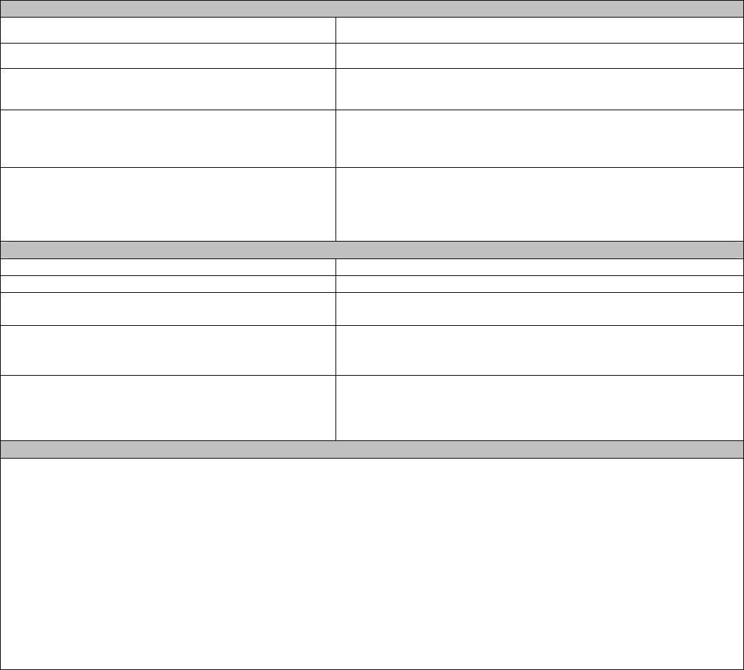
• File Transfer Client
The File Transfer Client is used to copy files and licenses to and from your local computer to the VWG.
The licenses and certificates used at the moment in the VWG license never expire. The File Transfer Client
can be used for advanced servicing if required.
Notes about Beta Released Versions
Please be aware of the following potential issues regarding the Beta versions of the products during
installation and commissioning.
Installing VT7000 Series Wireless Zigbee Thermostats
Description / Symptom Problem Possible Cause Work Around
Receiving same
refreshed messages at 2
separate devices
Duplicated wireless
Zigbee addresses Duplicated Zigbee
addresses created
during commissioning.
1) Assure that PAN ID and
Channel settings are secured
prior to network discovery.
2) Change PAN ID of all
thermostat and associated
gateway
3) Redo a wireless network
discovery
Station Crash during
group Edit/Delete Corrupted file tables Group edit / deletion
attempted. 1) Reboot wireless gateway
2) Assure nodes are edited
uniquely and not as part of a
group.
VWG will not reboot and
is rendered un
recoverable.
Serial traffic disrupting
station boot
sequence.
Network traffic present
during VWG
boot/discovery
sequence.
1) Shut down gateway power
2) Remove RF antenna during
initial boot up to allow option
card and station sufficient time
to stabilize.
3) Re-connect antenna
VWG will not reboot and
is rendered un
recoverable.
SPI corrupted. Option card (V-RFC)
replaced while power
remained on or battery
back up installed.
1) Assure power is battery pack-
up is completely disconnected
and that there is no power to
gateway prior to servicing
VWG or making internal
adjustments.
VWG not discoverable
by configuration tool. Network cable not
properly connected or
shorted between
VWG and Computer
Cross over cable not
used.
Ethernet switch not
used.
1) Assure cross over cable is
used when connecting from
VWG to PC.
Unable to logon to VWG
configuration tool. Logon unsuccessful Incorrect user name
and password. User name: admin
Password: <Blank>
19
Gateway Wireless Adapter LED Status Indicators
1 x 200ms short blink Power on
2 x 200ms short blinks Power on and card memory initialized properly
3 x 200ms short blinks Power on, card memory initialized properly and serial
communication with VWG main board active
4 x 200ms short blinks Power on, card memory initialized properly, serial
communication with VWG main board active and wireless
networks started successfully
4 x 200ms short blinks and 1 x 1500ms long
blink Power on, card memory initialized properly, serial
communication with VWG main board active, wireless
networks started successfully and wireless communication
with thermostats active
Thermostat Wireless Adapter LED Status Indicators
1 x 200ms short blink Power on
2 x 200ms short blinks Power on and communicating with thermostat
3 x 200ms short blinks Power on, communicating with thermostat and there is
connectivity to wireless network
4 x 200ms short blinks Power on, communicating with thermostat, connectivity to
wireless network and VWG is communicating with Wireless
thermostat
4 x 200ms short blinks and 1 x 1500ms long
blink Power on, communicating with thermostat, connectivity to
wireless network and VWG is communicating with Wireless
thermostat. Thermostat is also added to the exposed BACnet
database
System Troubleshooting Recommendations
1. If a thermostat is not detected by the VWG, verify that the LED is blinking at least 4 times. If it is only blinking
twice, ensure that the PAN and Channel of the thermostat is the same as the VWG it must communicate
with.
2. If there are no points associated to a specific thermostat, verify the LED pattern. If the LED is blinking 4 times
then the thermostat is communicating with the gateway, but its points have not been added to the LON or
BACnet database. Launch the Configuration utility tool and add that thermostat to the network / database
using the Add/Remove thermostat button.
3. When commissioning a network, it is recommended to use channels 25 and 26. Alternate these channels
between floors.
4. If a particular thermostat refuses to join the network and cannot be seen by the VWG. Please move
momentarily closer to the VWG until it has joined the network and it is added to the database. It can then be
re-located to its original position.