Victory Refrigeration Vf 1 Users Manual V Series Modified For End User Rev 01
VR-1 to the manual d6797b6b-07c1-a3e4-fd47-2be21208bf83
2015-02-03
: Victory-Refrigeration Victory-Refrigeration-Vf-1-Users-Manual-458430 victory-refrigeration-vf-1-users-manual-458430 victory-refrigeration pdf
Open the PDF directly: View PDF ![]() .
.
Page Count: 17
Installation, Operation and Troubleshooting Instructions
Manual Part No. 50853202
Rev: 01
Print Date: 12/26/02
110 Woodcrest Road, Cherry Hill, NJ 08003
Phone: (856) 428- 4200 Fax: (856) 428-7299 Website: www.victory-refrig.com
E-Mail: parts@victory-refrig.com ● order-entry@victory-refrig.com ●service@victory-refrig.com
For Models: VR-1, VR-2, VR-3, VR-1-G, VR-2-G, VF-1, VF-2, VF-3
V-Series Reach-In Refrigerators & Freezers
RReeffrriiggeerraattiioonn aatt iittss bbeesstt
PART OF AGA FOODSERVICE GROUP

Thank you for purchasing a Victory Refrigeration V-Series Refrigerator or Freezer! This
unit has passed our strict Quality Control Inspection and meets the high standards set
by Victory Refrigeration. You have made a quality investment that with proper
maintenance will give you years of service.
Please read the following installation and maintenance instructions before installing or
using your unit. If you have any questions, please call our Customer Service
Department at (856) 428-4200.
IMPORTANT INFORMATION - PLEASE READ
●●
Please read these instructions carefully before installing or using. If recommended
procedures are not followed, warranty claims will be denied.
●●
Your Warranty Registration information is located on the next page of this manual. Please
complete the card and submit it to Victory Refrigeration within 10 days of installation.
Failure to properly register equipment can void the warranty.
●●
Victory Refrigeration reserves the right to change specifications and product design
without notice. Such revisions do not entitle the buyer to corresponding
changes, improvements, additions or replacements for previously purchased equipment.
●●
A detailed Owners Manual with a troubleshooting guide, parts lists and additional
information can be ordered from the factory or may be downloaded free from the website at
www.victory-refrig.com.
THANK YOU

Warranty
(Continental USA Only)
The Seller warrants to the original purchaser, equipment manufactured by Seller to be free from defects in material and
workmanship for which it is responsible. The Seller's obligation under this warranty shall be limited to replacing or
repairing at Seller's option, without charge, F.O.B. Sellers factory, any part found to be defective and any labor and
material expense incurred by Seller in repairing or replacing such part, such warranty to be limited to a period of one
year from date of purchase or thirteen months from date of shipment from Seller's factory, whichever is earlier, provided
terms of payment have been fully met. All labor shall be performed during regular working hours. Overtime premium
charges will be at Buyer's expense.
Proof of purchase must be supplied to Seller to validate warranty. This warranty is valid only if equipment is properly
installed, started-up and inspected by the dealer or authorized Victory Service agent.
Removal or alteration of the serial/data plate from any equipment shall be deemed to release Seller from all warranty
obligations or any other obligations, expressed or implied.
This warranty does not cover Thermostat or Defrost Timer calibration and/or adjustment, freight damage, normal
maintenance items outlined in Owner's Manual, adjustment of door mechanisms or replacement of light bulbs, fuses
or batteries.
Any repairs or replacement of defective parts shall be performed by Seller's authorized service personnel. Seller shall
not be responsible for any costs incurred if the work is performed by other than Seller's authorized service personnel.
Reimbursement claims for part(s) or labor service costs must be made in writing. Model, cabinet serial numbers and
installation location must be shown on the claim. A receipted bill from the servicing agency must accompany the claim,
together with full details of the service problems, diagnosis and work performed. Victory reserves sole discretion
whether further documentation on a claim is to be submitted.
Seller shall not be liable for consequential damages of any kind which occur during the course of installation of
equipment, or which result from the use or misuse by Buyer, its employees or others of the equipment supplied
hereunder, and Buyer's sole and exclusive remedy against Seller for any breach of the foregoing warranty or otherwise
shall be for the repair or replacement of the equipment or parts thereof affected by such breach.
The foregoing warranty shall be valid and binding upon Seller if and only if Buyer loads, operates and maintains the
equipment supplied hereunder in accordance with the instruction manual provided to Buyer. Seller does not guarantee
the process of manufacture by Buyer or the quality of product to be produced by the equipment supplied hereunder
and Seller shall not be liable for any prospective or lost product or profits of Buyer.
THE FOREGOING WARRANTY IS EXCLUSIVE AND IN LIEU OF ALL OTHER EXPRESS AND IMPLIED
WARRANTIES WHATSOEVER. SPECIFICALLY THERE ARE NO IMPLIED WARRANTIES OF MERCHANTABILITY
OR OF FITNESS FOR A PARTICULAR PURPOSE.
The foregoing shall be Seller's sole and exclusive obligation and Buyer's sole and exclusive remedy for any action,
whether in breach of contract or negligence. In no event shall Seller be liable for a sum in excess of the purchase price
of the item.
ORIGINAL DATE OF INSTALLATION __________________________________________________________________
INSTALLATION COMPANY NAME ____________________________________________________________________
STREET_______________________________ CITY _____________________ STATE ______ ZIP CODE___________
DISTRIBUTOR’S NAME_____________________________________________________________________________
STREET_______________________________ CITY _____________________ STATE ______ ZIP CODE___________
You may register online at www.victory-refrig.com, fax this completed page to (856) 428-7299, or copy and mail form below to Victory.
*NOTE: The following mail-in form or online registration must be filled out and forwarded to Victory by the installer or customer within 10 days
after start-up. Failure to do this will invalidate the warranties. Retain this information for your records.
110 WOODCREST ROAD
CHERRY HILL, NJ 08003-3648
TEL: (856) 428-4200 ●FAX: (856) 428-7299
Cabinet Model No.______________________
Cabinet Serial No._________________
(Data plate information located inside cooler on
the upper left wall)
WARRANTIES NOT VALID UNLESS REGISTERED AT
FACTORY WITHIN 10 DAYS AFTER START-UP DATE.

Proper installation is the first step to operation. We recommend that your refrigerator or freezer be installed by
an authorized Victory Certified Installer.
Receiving Shipment
All units are performance tested and thoroughly inspected prior to shipment. Upon leaving the factory, all units are in
perfect condition. Upon receipt, examine the exterior of the shipment packaging for any signs of rough handling. If the
cabinet is damaged, it should be noted on the delivery slip or bill of lading and signed. A claim must be filed immediately
against the carrier indicating the extent and estimated cost of damage incurred.
Uncrating
Tools Needed : 3/4” Box Wrench ●●Adjustable Wrench ●●Level
WARNING: Never lay your refrigerator or freezer down on either its back, front or sides. This allows compressor oil into
the refrigerant lines which can damage the compressor at start-up. If the unit is laid down, it must be set upright for a
minimum of 12 hours before starting the compressor. Failure to adhere to the above recommendation will void the warranty.
1. Split plastic wrap along one of the cardboard posts. Remove and discard all packaging material, tape and interior
components.
2. Move cabinet as close to final location as possible before removing skid.
3. Remove the shipping skid by tipping the cabinet forward. Remove the shipping bolts with 3/4” box wrench while
the cabinet is held in one direction. Repeat this procedure while the cabinet is held in the opposite direction.
4. Use extreme caution when removing the wooden skid, especially when the last bolt is removed. If not properly
blocked, the skid will fall to the floor.
Locating Your New Storage Refrigerator or Freezer
Consider the following when selecting a location for your refrigerator or freezer:
1. Clearance - There must be a minimum clearance of 10” between the top of the refrigerator or freezer and the ceiling.
2. Floor Load - The floor on which the cabinet will rest must be free of vibration and suitably strong enough to support
the combined weights of the cabinet plus the maximum product load.
3. Ventilation - The air cooled, self-contained refrigerator or freezer requires a sufficient amount of cool, clean air. Avoid
placing the refrigerator near heat generating equipment such as ovens, ranges, heaters, fryers, steam kettles, etc., and
out of direct sunlight. Avoid locating the self-contained refrigerator in an unheated room, or where the room
temperature may be below 55°F.
Installing Casters or Legs
Refrigerators and freezers are shipped with 1/2” single stud mounted legs or casters.
1. Casters / legs must be screwed by hand into the threaded holes located on the case bottom (*Note: Once the caster
cannot be turned, take a 3/4” box wrench and tighten the nut in between the mounting plate and wheel of the caster
until it is snug).
2. Tilt the cabinet in one direction approximately eight inches and block it securely with several pieces of 2 x 4 lumber or
other suitable material.
3. Screw in the two left or right casters /legs.
4. Repeat this procedure to install the other casters/legs.
Leveling
Cabinets must be leveled when installed. Failure to level your cabinet may result in doors not sealing, closing properly or
condensate water not draining properly.
Casters - Cabinets with casters can be leveled by placing large flat washers in between 1/2” stud and holes located
on the case bottom.
Legs - Rotate the foot of the leg with an adjustable wrench to achieve desired height for leveling.
1
INSTALLATION INSTRUCTIONS

Cabinet Cleaning
Prior to placing your new refrigerator and all shelves, pans and slides into operation, it is advisable that the interior be
washed thoroughly with a mild detergent and water solution. Rinse with clear water and a sanitizing solution. Allow cabinet
to air dry.
Installing Shelves
All cabinets with shelves are supplied with pilasters and shelf clip supports. Shelves are easily installed by inserting the
shelf support clips into the pilasters so they fit tightly. Align the shelf so the smaller fill wires run from front to rear and rest
the shelf on the clips.
Electric Supply
Wiring should be done by a qualified electrician in accordance with local electrical codes. Aseparate ground wire must
be supplied for all installations. A properly wired refrigerator or freezer will assure proper operation. Electrical supply
requirements are on the cabinet serial/data plate. It is recommended that a direct, properly protected line of the proper
size wire be installed from the main supply to your refrigerator or freezer. To assure that the correct voltage is being
supplied, while the refrigerator or freezer is in operation take a voltage reading at the motor-compressor electrical
connections, or as close to the motor-compressor as possible.
All refrigerator or freezer electrical systems are internally grounded.
Temperature Control
Temperature control should be set to maintain a temperature of 38°F (3.3°C) to 40°F (4.4°C) for refrigerators, and 0°F
(-17°C) to -5°F (-20.5°C) for freezers.
Adjusting Dial Thermometer (if required)
Installing Replacement Door Gasket (if required)
Removing
Beginning at one corner, pry gasket loose from the retaining strip. Peel remainder of gasket from the door and discard.
Replacing
Before replacing, be sure the gasket and door are at room temperature. (If necessary, soak the gasket in
warmwater to make it more pliable.) Align new gasket frame on the door retainer strip. Starting at one corner,
press each corner of the gasket into the retainer strip. Once started, the gasket can be easily inserted around the entire
perimeter of the door by simply press rolling into place.
Installation Checklist
After the cabinet has been installed, leveled and cleaned as described, refer to the following checklist prior to start-up.
Check for proper electrical hook-up.
Check exposed refrigeration line connections for leaks. Make sure refrigeration lines are not dented, kinked or rubbing.
Check condenser fan for freedom to rotate without striking any stationary members.
Check that cabinet is level.
Product Load
After the refrigerator or freezer has been started and reaches the proper storage temperatures, food may be loaded. For
optimum energy efficiency, we recommend allowing a 1-1/2” clearance between the interior cabinet wall and product load.
2
Check the cabinet temperature by using an accurate hand held dial or digital thermometer
placed next to the thermometer sensing bulb (located in the upper right hand corner of your
cabinet). If the dial thermometer on the cabinet grill matches the test thermometer (±1°F)
do not adjust.
If it does not match, remove the dial thermometer lens with a small screwdriver. To adjust
the temperature needle, insert a small screwdriver in the slotted screw on the needle. Hold
the wide end of the needle to keep it from moving and turn the screw clockwise or
counterclockwise to adjust as needed. Release the needle and remove the screwdriver.
Verify new needle setting with the test thermometer. Replace the dial thermometer lens.

3
Cabinet Cleaning
Victory Refrigeration recommends periodic internal and exterior cleaning as outlined below.
Daily Exterior Cleaning
1. Clean surface with a sponge and cleaning solution. Use a non-abrasive cleaner that does not contain chlorine.
2. Polish with a soft cloth, wiping with the grain of the metal.
3. Once a week wipe with a film cutting agent to maintain shine.
Weekly Interior Cleaning
1. Remove all food, food related items and shelves.
2. Turn the unit off.
3. Remove loose food particles from interior floors, walls and ceiling.
4. Scrub all interior surfaces with warm detergent solution 100 °F - 120°F (38°C - 39°C) and a nylon bristled brush.
5. Rinse with clear water and allow to air dry.
6. Reinstall shelves.
7. Return power (electrical) to unit by resetting circuit breaker.
8. Return food to cabinet when temperature indicator reaches safety zone.
Condenser Maintenance
To keep your cabinet running efficiently, it is recommended that you clean the condenser once every three months.
However, once a month is recommended if the unit is located near cooking equipment which produces grease laden
vapors, i.e. fryers, grills, steam kettles, etc.
1. Disconnect power by switching circuit breaker to “OFF” position.
2. Remove the front grill by removing the two (2) screws on the inside of the grill at each end, then lift the panel up
and straight out.
3. Use a vacuum cleaner with proper brush attachments to clean the condenser, motor-compressor and related parts.
4. In extreme cases of dust and grease buildup, the condenser fins may require blowing out with compressed air or
cleaning with a degreasing agent.
5. Turn circuit breaker to “ON” position.
WARNING: Failure to keep condenser clean may cause premature failure of motor-compressor which
will NOT be covered by warranty.
Lubrication
Unless otherwise specified, all Victory refrigerators are equipped with oilless type motors. The motor-compressor is a
sealed unit and is constantly lubricated when in operation. The condenser and the evaporator motors are equipped with
lifetime oiled bearings which never need to be oiled.
3
PERIODIC MAINTENANCE

4
BEFORE CALLING SERVICE GUIDE FOR COMMON PROBLEMS
Caution: Disconnect Power Supply Prior to Attempting Any Service!

*Note: All field replacement parts may not be stated on this parts list. For additional information or assistance, contact the factory.
5
Item Description Part Number Quantity
1 Door Hinge Assembly 10685101 2 per door
2 Hinge Barrel 50520102 1 per hinge assembly
3 Hinge Cover 50520105 1 per hinge assembly
4 Hinge Base 50520103 1 per hinge assembly
5 Hinge Cam 50520106 1 per hinge assembly
6 Hinge Base Screw 50678801 3 per hinge assembly
7 Hinge Barrel Screw 50678801 2 per hinge assembly
8 Keeper, Single Door 01368801 1 per one & three section unit
8 Keeper, Double Door 01368802 1 per two & three section unit
9 Screw, Door Keeper 50585702 2 per door keeper
10 Door Assembly, RH Full Door w/ Rectangular Handle -
* Prior to 9/3/02
10791102 per all standard section units
10 Door Assembly, RH Full Door w/ Coved Handle -
* After 9/3/02
10791109 per all standard section units
10 Door Assembly, LH Full Door w/ Rectangular Handle -
* Prior to 9/3/02
10791101 1 per two & three section units
10 Door Assembly, LH Full Door w/ Coved Handle -
* After 9/3/02
10791110 1 per two & three section units
10 Door Assembly, LH Half Door w/ Rectangular Handle -
* Prior to 9/3/02
10794105 * available upon request *
10 Door Assembly, LH Half Door w/ Coved Handle -
* After 9/3/02 10818203
* available upon request *
10 Door Assembly, RH Half Door w/ Rectangular Handle -
* Prior to 9/3/02
10794106 * available upon request *
10 Door Assembly, RH Half Door w/ Coved Handle -
* After 9/3/02
10818204
* available upon request *
11 Door Gasket, Full -
* Cabinets Built Prior to 9/3/02
50827801 1 per full length metal door
11 Door Gasket, Full -
* Cabinets Built After 9/3/02
50879501 1 per full length metal door
11 Door Gasket, Half -
* Cabinets Built Prior to 9/3/02
50827802 * available upon request
11 Door Gasket, Half -
* Cabinets Built After 9/3/02
50879502 * available upon request *
12 Retainer, Door Gasket (Top & Bottom) 50827701 2 per full & half length door
13 Retainer, Door Gasket (Sides for Full Door) 50827601 2 per full length door
13 Retainer, Door Gasket (Sides for Half Door) 50827602 * available upon request *
14 Plugs 50829101 * available upon request *
15 Door Pan, Full 50827901 1 per full length door
15 Door Pan, Half 50827902 * available upon request *
16 Lock & Key Set 50597107 1 per door
17 Door Handle, Rectangular -
* Cabinets Built Prior to 9/3/02
50828001 1 per door
17 Door Handle, Coved -
* Cabinets Built After 9/3/02
50867701 1 per door
18 Breaker Strip, Top 90317003 1 per section
19 Breaker Strip, Bottom 90317002 1 per section
20 Breaker Strip, Side (Full & Half) 90317001 2 per section
21 Bulb, Light 50828801 1 per unit
22 Socket, Light 50826601 1 per unit
23 Legs (Black in Color) 50671801 4 per unit
24 Casters, 5” Swivel (with Brake, 6” Overall Height) 50096002 4 per unit
25 Heater Wire, Door Frame 50707501 1 per section
26 Shim, Fascia 50720701 * available upon request *
27 Shim, Door 50538601 * available upon request *
Cabinet & Hinged Metal Door Parts

6
(*NOTE: WARRANTY DOES NOT COVER GLASS BREAKAGE! THE GLASS PANEL IS NOT SERVICEABLE. ENTIRE DOOR MUST BE REPLACED.)
Vision panel door is interchangeable with standard solid door. Door is left / right reversible
by inverting hinge mounting.
*Vision panel door is intended for operation in maximum 85
°°
F, 55% RH environment for
refrigerated case (38
°°
F) applications only!
Hinged Vision Panel Door Parts
Item Description Part Number Quantity
1 Door Gasket, Full
-
* Cabinets Built Prior to 9/3/02 50827801 1 per full length door
1 Door Gasket, Full -* Cabinets Built After 9/3/02 50879501 1 per full length door
2 Lock & Key Set 50597107 1 per door
3
Ass’y, LH Full Door w/ Vision Panel & Rectangular Handle
-
* Prior to 9/3/02 10791107 1 per cabinet section
3
Ass’y, LH Full Door w/ Vision Panel & Coved Handle -
* After 9/3/02
10818301 1 per cabinet section
3 Ass’y, RH Full Door w/ Vision Panel & Rectangular Handle
-
* Prior to 9/3/02 10791108 1 per cabinet section
3 Ass’y, RH Full Door w/ Vision Panel
& Coved Handle -
* After 9/3/02 10818302 1 per cabinet section
4 Base, Hinge 50520103 1 per hinge assembly
5 Cam, Hinge 50520106 1 per door
6 Base Screw, Hinge 50678801 3 per hinge assembly
7 Barrel, Hinge 50520102 1 per hinge assembly
8 Barrel Screw, Hinge 50678801 2 per hinge assembly
9 Cover, Hinge 50520105 1 per hinge assembly
10 Shim, Door 05312701 *available upon request
11 Hinge Assembly, Top or Bottom 10685101 2 per door

Thermometer & Grill
Shelving & Accessories
7
Item Description Part Number Quantity
1 Grill Assembly w/o Thermometer, 1 Section Refrigerator 10809204 1 per one section refrigerator unit
1 Grill Assembly w/o Thermometer, 2 Section Refrigerator 10809205 1 per two section refrigerator unit
1 Grill Assembly w/o Thermometer, 3 Section Refrigerator 10809206 1 per three section refrigerator unit
1 Grill Assembly w/o Thermometer, 1 Section Freezer 10809207 1 per one section freezer unit
1 Grill Assembly w/o Thermometer, 2 Section Freezer 10809208 1 per two section freezer unit
1 Grill Assembly w/o Thermometer, 3 Section Freezer 10809209 1 per three section freezer unit
2 “Victory” Logo -
* for Cabinets Built Prior to 9/9/02
50853501 1 per all refrigerator or freezer units
2 “Victory” Logo, Refrigerator -
* for Cabinets Built After 9/9/02 50883201
1 per all refrigerator units
2
“Victory” Logo, Freezer -
* for Cabinets Built After 9/9/02 50883301 1 per all freezer units
3 Thermometer, Refrigerator Dial 50827403 1 per all refrigerator units
3 Thermometer, Freezer Dial 50827404 1 per all freezer units
3 Thermometer, Refrigerator & Freezer N/A 1 per all refrigerator or freezer units
4 Screw 50267901 4 per all refrigerator or freezer units
5 Bracket, Dial Thermometer Mounting 05315501 1 per all refrigerator or freezer units
6 Screw, Thumb 50684201 1 per all refrigerator or freezer units
7 Upper Case End 05315601 2 per all refrigerator or freezer units
8 Brace, Upper Case End 05315701 2 per all refrigerator or freezer units
9 Screw 50692301 4 per Upper Case End Brace
10 End Panel, Field Replacement 01333320 2 per all refrigerator or freezer units
11 Nut 50081701 2 per all refrigerator or freezer units
1
*Note: All field replacement parts may not be stated on this parts list. For additional information or assistance, contact the factory.
Number of Sections
Item One Section Two Section Three Section Part Description
No. Section 1 Section 2 Section 1 Section 2 Section 3 No.
1 X X X X X X 03221003 Aluminum Pilaster 9/32” Deep x
54-1/2” Long
1 X X X X X X 03221004 Stainless Steel 9/32” Deep x
54-1/2” Long
2 X X X X X X 50022501 Shelf Support Clip
2 X X X X X X 50022601 Stainless Steel Shelf Support Clip
3 50597703 50597803 50597803 50597803 50597903 50597803 Stainless Steel Shelves
3 50597706 50597806 50597806 50597806 50597906 50597806 Epoxy Coated Shelves
50828401 Nylon Inserts
50828901 Tapping Screws

Item Description Part Number Quantity
1 Evaporator Housing Assembly 10534201 1
2 Evaporator Housing Assembly Cover 10534102 1
3 Screen, Vent -
* for Cabinets Built Prior to 8/5/02
50177401 1
3 Bushing, Snap -
* for Cabinets Built After 8/5/02
50880201 1
4 Vent, Breather -
* for Cabinets Built Prior to 8/5/02
50097901 1
4 Bumper, Rubber -
* for Cabinets Built After 8/5/02
50240301 1
5 Fan Blade, Evaporator 50598001 1
6 Fan Motor, Evaporator 50639801 1
7 Bracket, Evaporator Fan Motor 04415201 1
8 Fan Panel 04404803 1
9 Electrical Box Assembly 10806901 1
10 Coil, Evaporator 50617101 1
11 Accumulator 50180701 1
12 Heat Exchanger 10776901 1
13 Capillary Tube 50199002 1
14 Temperature Control 50616201 1
15 Drain Pan, Evaporator 10511103 1
16 Drain Line 50245001 1
17 Latch, Lock 50554302 4
18 Latch, Strike Hook 50554303 4
19 Terminal Board, 1 to 4 50684401 1
20 Cordset, Heater and Light 50836801 1
21 Harness, Cord and Plug 115v/15A 50828201 1
22 Harness, Condenser Unit Receptacle 50819901 1
23 Drain Pan, Condensate (not shown) 50876101 1
24 Liquid Line Dryer 50730801 1
25 Fan Motor, Condenser (not shown) 50193101 1
One Section Refrigerator Components
Electrical Box Assembly
9
14
19 20
21
22
8
*Note: All field replacement parts
may not be stated on this
parts list. For additional
information or assistance,
contact the factory.

Two & Three Section Refrigerator Components
9
Item Description Part Number Quantity
1 Evaporator Housing Assembly 10536801 1
2 Evaporator Housing Assembly Cover 10536902 1
3 Screen, Vent - * for Cabinets Built Prior to 8/5/02 50177401 1
3 Bushing, Snap - * for Cabinets Built After 8/5/02 50880201 1
4 Vent, Breather - * for Cabinets Built Prior to 8/5/02 50097901 1
4 Bumper, Rubber - * for Cabinets Built After 8/5/02 50240301 1
5 Fan Blade, Evaporator 50598001 2
6 Fan Motor, Evaporator 50639801 2
7 Bracket, Evaporator Fan Motor 04415201 2
8 Fan Panel 04403702 1
9 Electrical Box Assembly, Two Section 10806901 1
9 Electrical Box Assembly, Three Section 10807001 1
10 Coil, Evaporator 50616801 1
11 Accumulator (for Two Section) 50293701 1
11 Accumulator (for Three Section) 50184101 1
12 Heat Exchanger (for Two Section) 10548601 1
12 Heat Exchanger (for Three Section) 10596201 1
13 Capillary Tube (for Two Section) 50197601 2
13 Capillary Tube (for Three Section) 50199001 2
14 Temperature Control 50616201 1
15 Drain Pan, Evaporator 10511104 1
16 Drain Line 50245001 1
17 Latch, Lock 50554302 4
18 Latch, Strike Hook 50554303 4
19 Terminal Board, 1 to 4 50684401 1
20 Cordset, Heater and Light 50836801 1
21 Harness, Cord and Plug 115v/15A, Two Section 50828201 1
21 Harness, Cord and Plug 115v/20A, Three Section 50828202 1
22 Harness, Condenser Unit Receptacle 50819901 1
23 Drain Pan, Condensate (not shown; for two section refrigerator only) 50876101 1
24 Liquid Line Dryer 50730801 1
25 Fan Motor, Condenser (not shown; for two section refrigerator only) 50193101 1
Electrical Box Assembly
9
14
19 20
21
22
*Note: All field replacement parts
may not be stated on this
parts list. For additional
information or assistance,
contact the factory.

One Section Freezer Components
Electrical Box Assembly
Item Description Part Number Quantity
1 Evaporator Housing Assembly 10534201 1
2 Evaporator Housing Assembly Cover 10534102 1
3 Screen, Vent - * for Cabinets Built Prior to 8/5/02 50177401 1
3 Bushing, Snap - * for Cabinets Built After 8/5/02 50880201 1
4 Vent, Breather - * for Cabinets Built Prior to 8/5/02 50097901 1
4 Bumper, Rubber - * for Cabinets Built After 8/5/02 50240301 1
5 Fan Blade, Evaporator 50598001 1
6 Fan Motor, Evaporator 50639801 1
7 Bracket, Evaporator Fan Motor 04415201 1
8 Fan Panel 04404803 1
9 Electrical Box Assembly 10806301 1
10 Coil, Evaporator 50617201 1
11 Accumulator 50180701 1
12 Heat Exchanger 10723101 1
13 Capillary Tube 50793601 2
14 Temperature Control 50616101 1
15 Drain Pan, Evaporator 10511103 1
16 Drain Line 50245001 1
17 Latch, Lock 50554302 4
18 Latch, Strike Hook 50554303 4
19 Terminal Board, 1 to 4 50684401 1
20 Cordset, Heater and Light 50836801 1
21 Harness, Cord and Plug 115v/15A 50828201 1
22 Harness, Condenser Unit Receptacle 50837101 1
23 Drain Pan, Condensate (not shown) N/A -
24 Defrost Timer 50197302 1
25 Heater Safety (2 wire) 50599401 1
26 Probe Bracket 50244101 1
27 Junction Block 50606001 1
28 Fan Delay (3 wire) 50599501 1
29 Defrost Heater 50620501 1
30 Liquid Line Dryer 50730801 1
31 Power Relay 50369401 1
9
19 20
21
22
24
10
*Note: All field replacement parts
may not be stated on this
parts list. For additional
information or assistance,
contact the factory.

Two & Three Section Freezer Components
11
Item Description Part Number Quantity
1 Evaporator Housing Assembly 10536801 1
2 Evaporator Housing Assembly Cover 10536902 1
3 Screen, Vent - * for Cabinets Built Prior to 8/5/02 50177401 1
3 Bushing, Snap - * for Cabinets Built After 8/5/02 50880201 1
4 Vent, Breather - * for Cabinets Built Prior to 8/5/02 50097901 1
4 Bumper, Rubber - * for Cabinets Built After 8/5/02 50240301 1
5 Fan Blade, Evaporator 50598001 2
6 Fan Motor, Evaporator 50639801 2
7 Bracket, Evaporator Fan Motor 04415201 2
8 Fan Panel 04403702 1
9 Electrical Box Assembly (refer to “Electrical Assembly with Figure 6-5) 10806301 1
9 Electrical Box Assembly, Three Section 10806401 1
10 Coil, Evaporator 50616901 1
11 Accumulator 50181401 1
12 Heat Exchanger, Two Section 10738401 1
12 Heat Exchanger, Three Section 10768601 1
13 Capillary Tube 50198902 2
13 Capillary Tube 50793501 2
14 Temperature Control 50616101 1
15 Drain Pan, Evaporator 10511104 1
16 Drain Line 50245001 1
17 Latch, Lock 50554302 4
18 Latch, Strike Hook 50554303 4
19 Terminal Board, 1 to 4 50684401 1
20 Cordset, Heater and Light 50836801 1
21 Harness, Cord and Plug 115v/15A 50828201 1
22 Harness, Condenser Unit Receptacle 50837101 1
23 Drain Pan, Condensate (not shown) N/A -
24 Defrost Timer 50197302 1
25 Heater Safety (2 wire) 50599401 1
26 Probe Bracket 50244101 1
27 Junction Block 50606001 1
28 Fan Delay (3 wire) 50599501 1
29 Defrost Heater 50596301 1
30 Liquid Line Dryer 50730801 1
31 Power Relay 50369401 1
Electrical Box Assembly
9
19 20
21
24
14
22
*Note: All field replacement parts
may not be stated on this
parts list. For additional
information or assistance,
contact the factory.
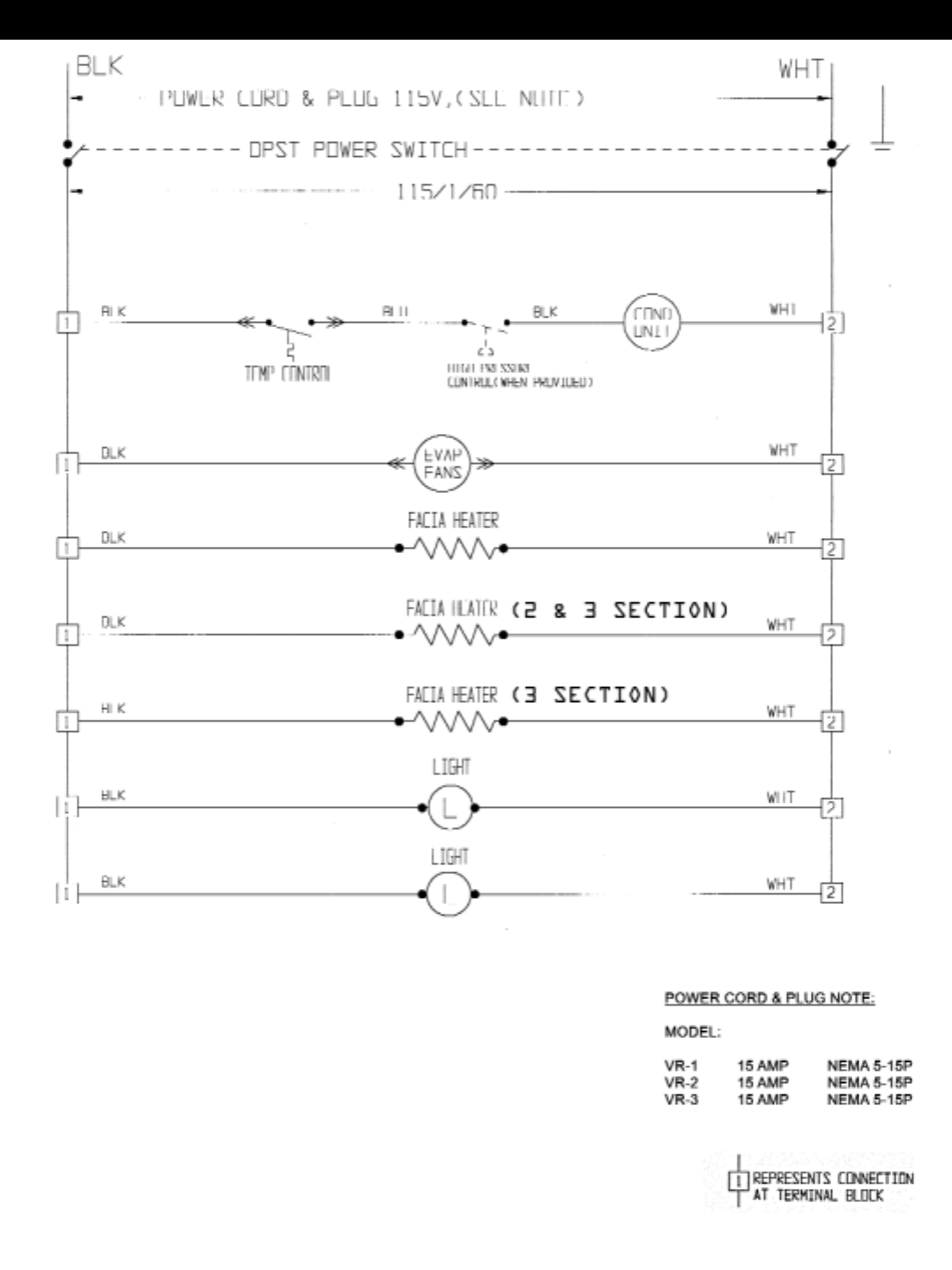
1, 2 & 3 Section Refrigerator Wiring Diagram
12
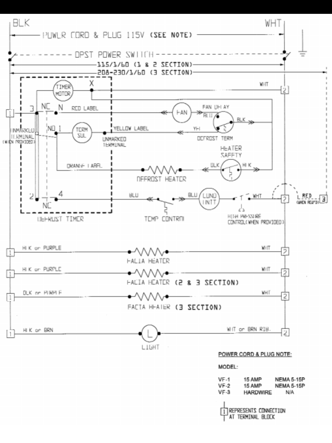
1, 2 & 3 Section Freezer Wiring Diagram
13

Victory Refrigeration Inc
110 Woodcrest Road
Cherry Hill, NJ 08003-3648
Tel: (856) 428-4200
Fax: (856) 428-7299
Web: www.victory-refrig.com
E-mail: service@ victory-refrig.com
or
parts@victory-refrig.com
