ViewSonic VSVPD10000203 Wireless View Pad User Manual 520sec1
ViewSonic Corporation Wireless View Pad 520sec1
UserManual.wiki
>
ViewSonic
>
VSVPD10000203 User Manual
Revised Manual
Navigation menu
Upload a User Manual
Namespaces
Wiki Guide
HTML
PDF
Info
Views
User Manual
Discussion / Help
Navigation

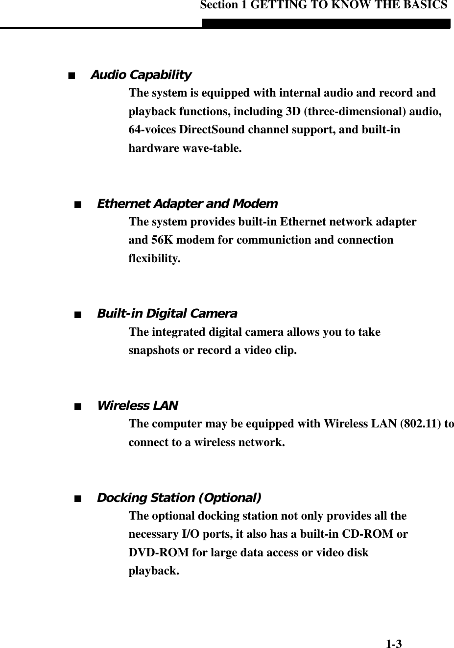

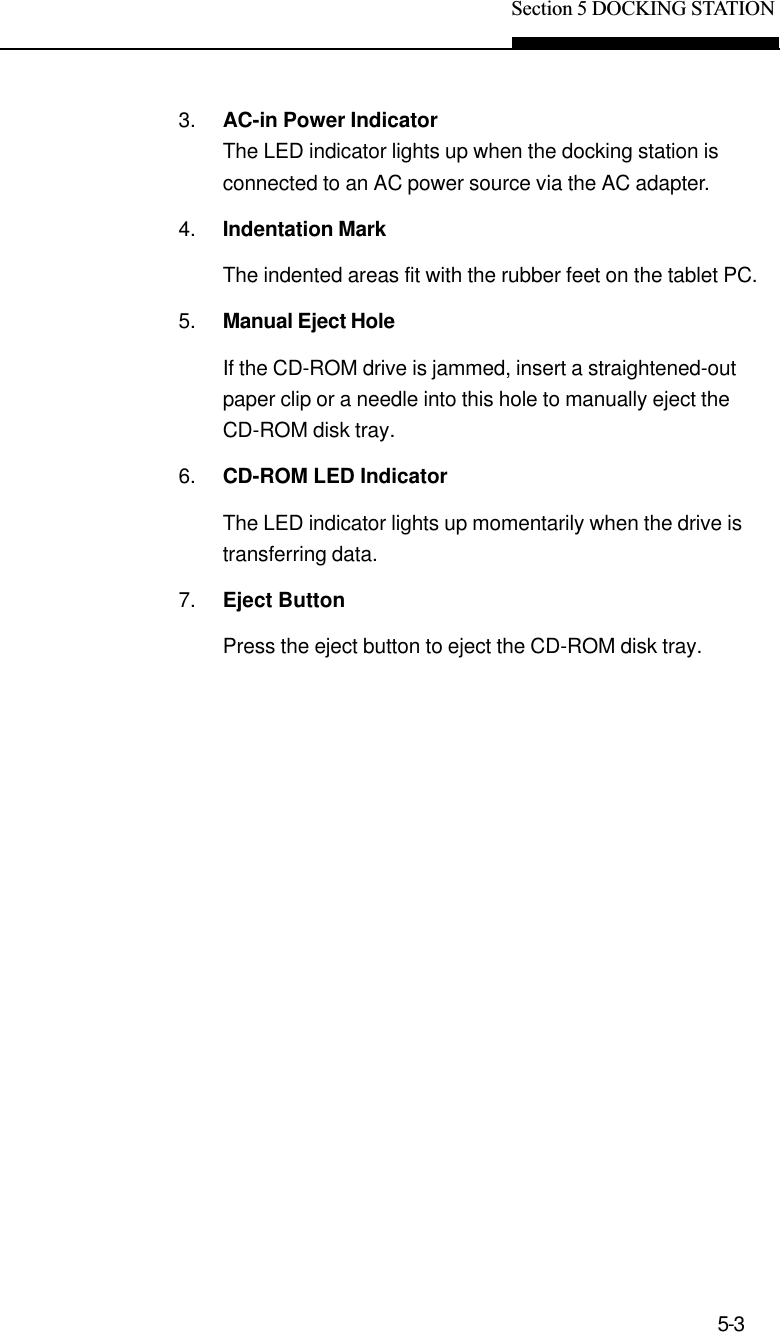
![1-6USER`S MANUALPanel > Power Management] to access the utility. Go toSection 2 for more details on system suspend function.8. LCD DisplayThe panel is where the system`s data is displayed.9. Built-in MicrophoneThe built-in microphone records sound.10. Consumer Infrared Port (1)The CIR port is used to link with a CIR-type wirelesskeyboard.11.Built-in Stereo SpeakersThe built-in speakers output the sound in stereo.12. StandThe stand allows the tablet PC to be positioned vertically(Portrait Mode) or horizontally (Landscape Mode) on adesktop.13. Rubber FeetThe rubber feet allows the tablet PC to be positioned on itsside on the desk.Note:If you encounterdifficulties withIrDA (infrared port)operation, go toSection 5 to learn tosolve the problems.Warning:Do not place anyheavy objects onthe LCD panel. Itmay damage thedisplay.Note:The tablet PC can bepositioned horizontally.You will need to rotatethe display content 90degrees via the `Pivot`software. Go to How toUse the Tablet PC inLandscape Mode Sectionto learn more.](https://usermanual.wiki/ViewSonic/VSVPD10000203/User-Guide-233988-Page-6.png)
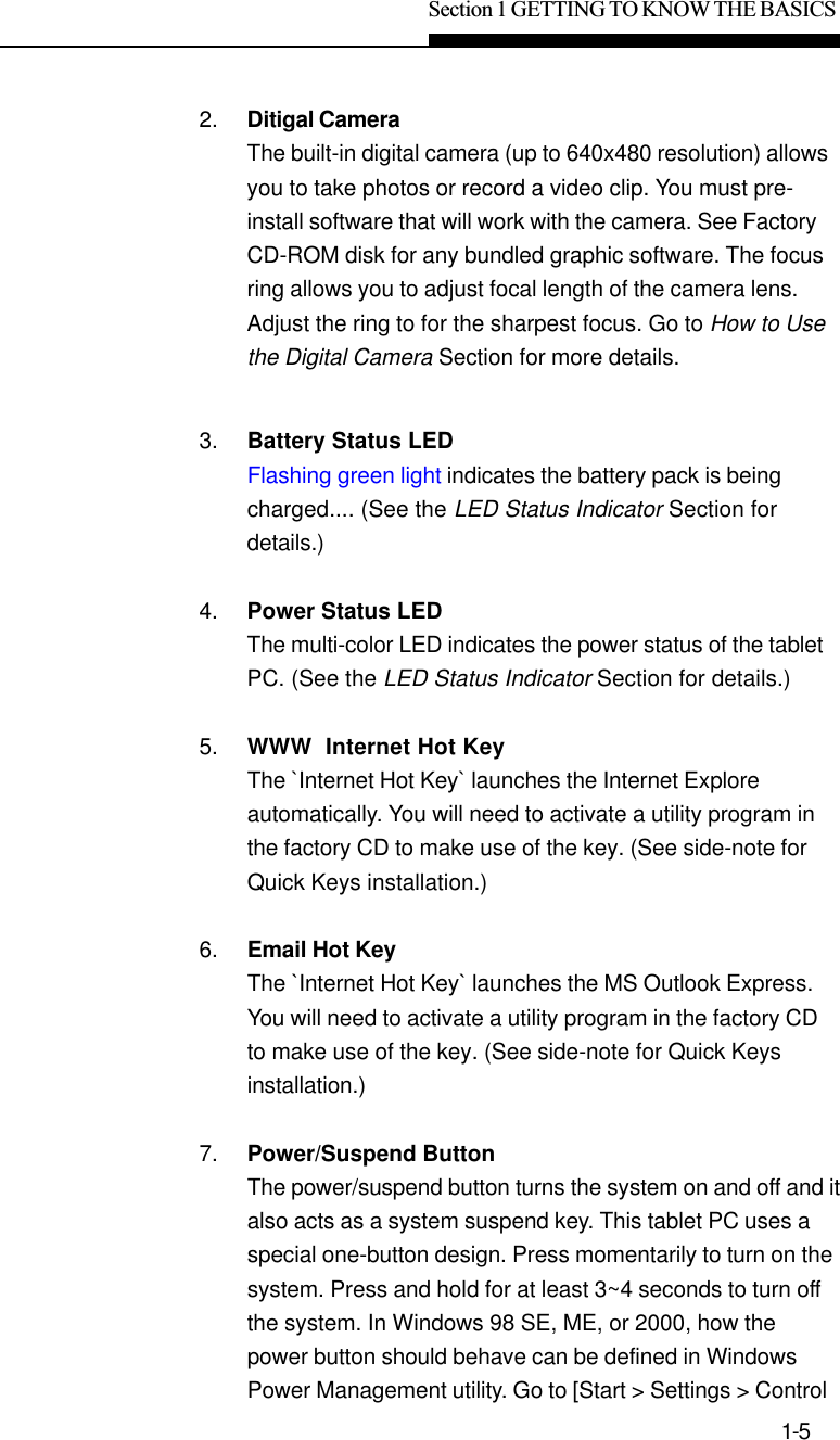
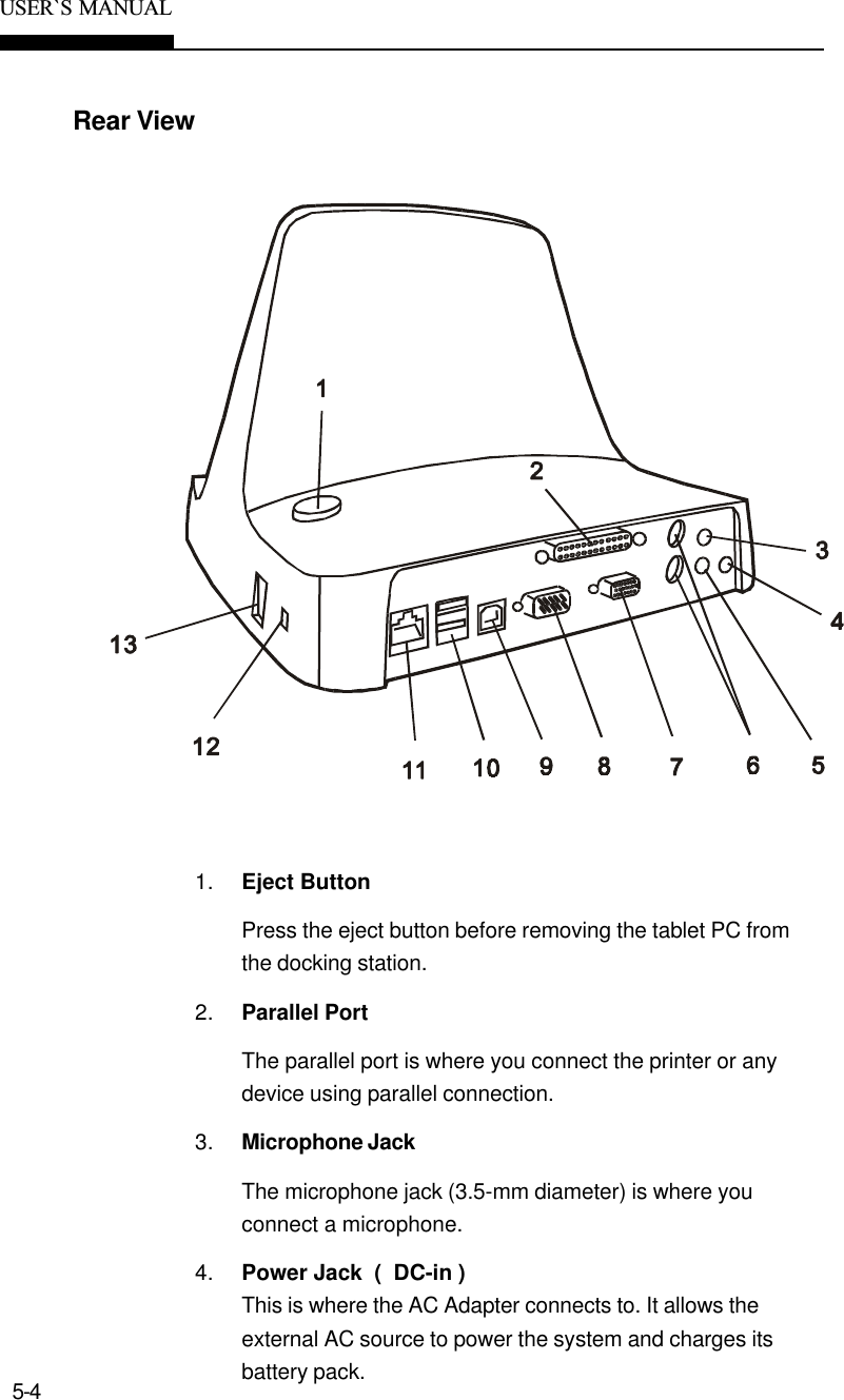
![Section 1 GETTING TO KNOW THE BASICS1-17Network AdapterYour tablet PC is equipped with a 100Base-TX Ethernet networkadapter. Connecting the active LAN cable to the RJ-45 LAN portlocated in the back of the system. This allows you to access andtransmit data in the local area network.Connecting to the NetworkUse Unshielded Twisted Pair (UTP) Ethernet cable only.1. Insert one end of the UTP cable into the network con-nector until the connector snaps securely into thereceptacle.2. Either connect the other end of the cable to an RJ-45jack wall outlet or to an RJ-45 port on a UTP concentra-tor or hub in the network.Cabling Restriction for NetworksThe following restrictions should be observed for 100BASE-TXnetworks:nThe maximum cable run length is 100 meters(m) (328 feet[ft]).nFor 100-Mbps operation, use Category 5 wiring andconnections.Consult Windows manual and / or Novell Netware user‘s guide forthe software installation, configuration, operation of the network.](https://usermanual.wiki/ViewSonic/VSVPD10000203/User-Guide-233988-Page-17.png)
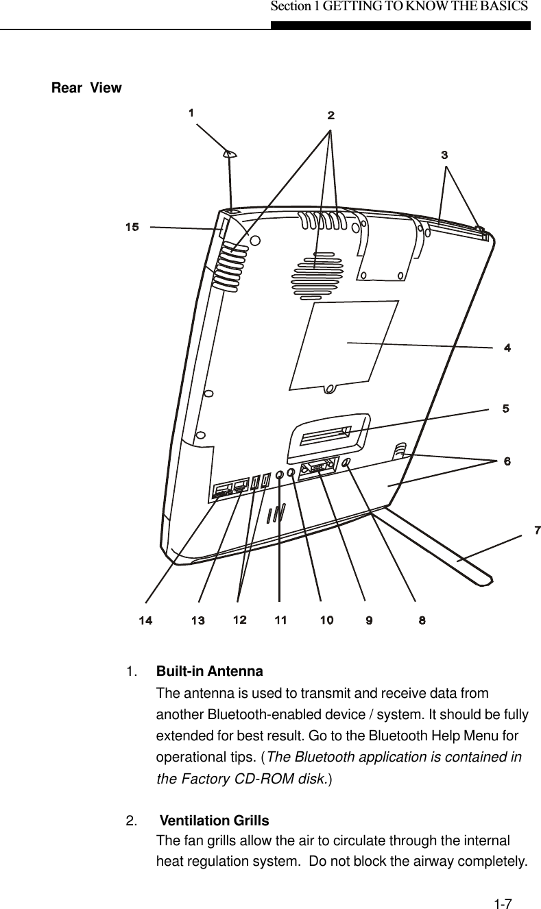
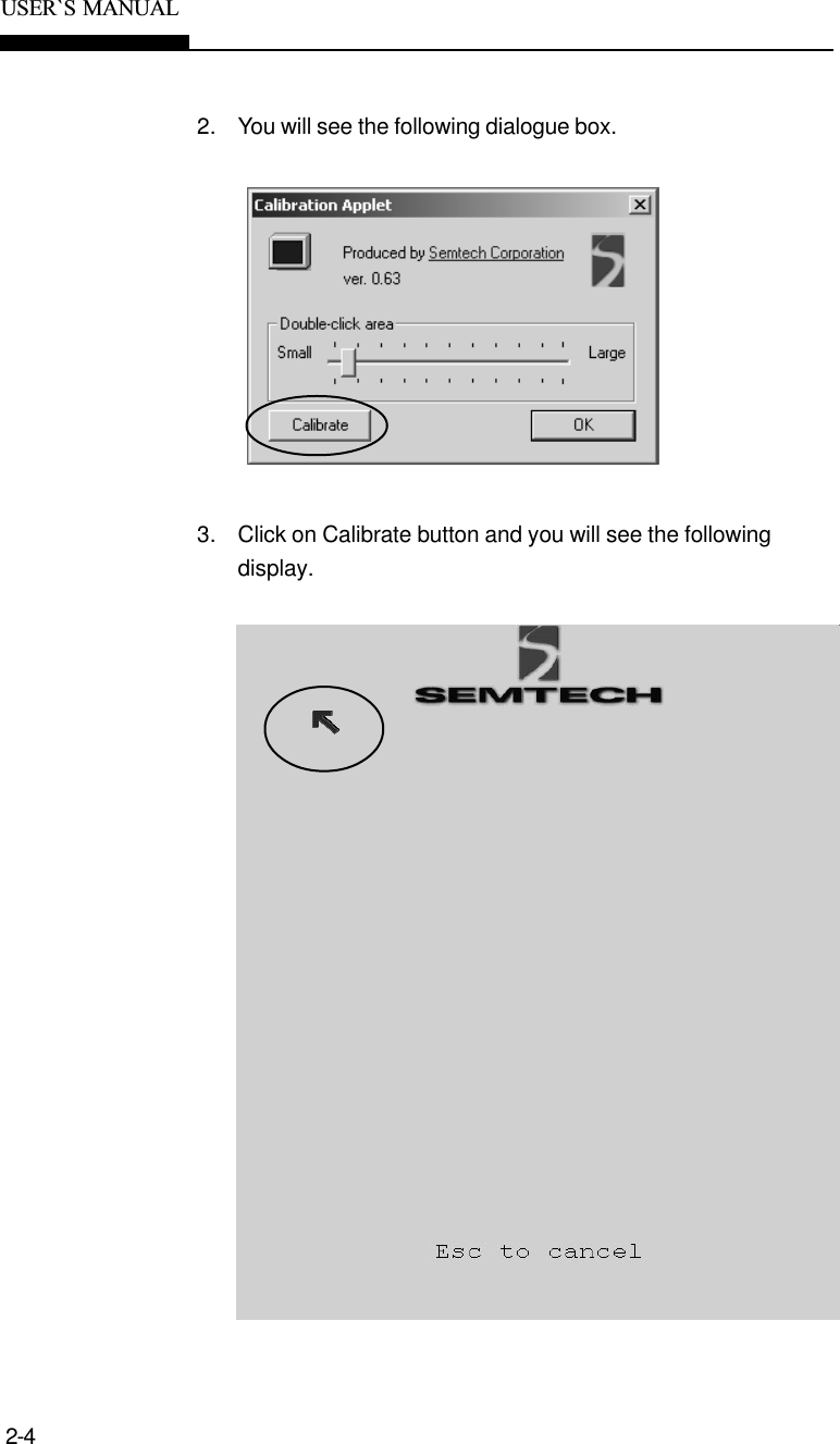
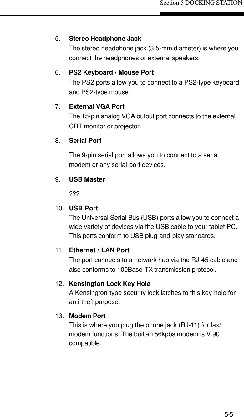
![Section 2 Using Software2-3Touch Screen CalibrationAlthough touch screen calibration may have already beenperformed at the factory, there are times that it needs to be re-calibration for higher accuracy.The touch screen is a touch-sensitive device. It is a membraneon top of the LCD display. It responds to mechanical pressure onthe screen surface. You can navigate the cursor using the stylus(pen). When you notice the stylus tip does not correspond wellor match point-to-point with the cursor, you then need to re-calibrate the touch screen device.To calibrate the touch screen, do the following:1. To go [Start > Settings > Control Panel] and double-click onTouch Screen Calibrator icon.](https://usermanual.wiki/ViewSonic/VSVPD10000203/User-Guide-233988-Page-20.png)
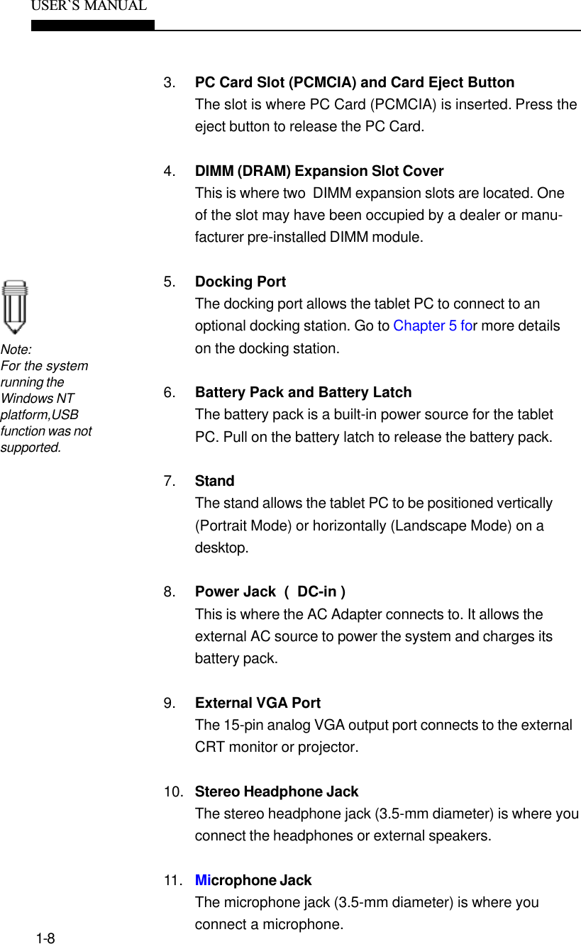
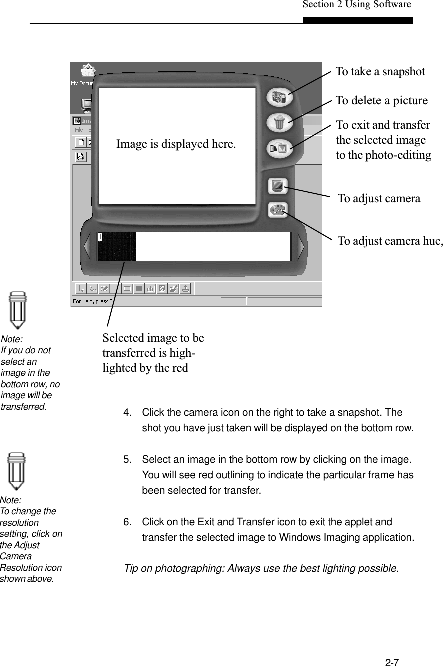
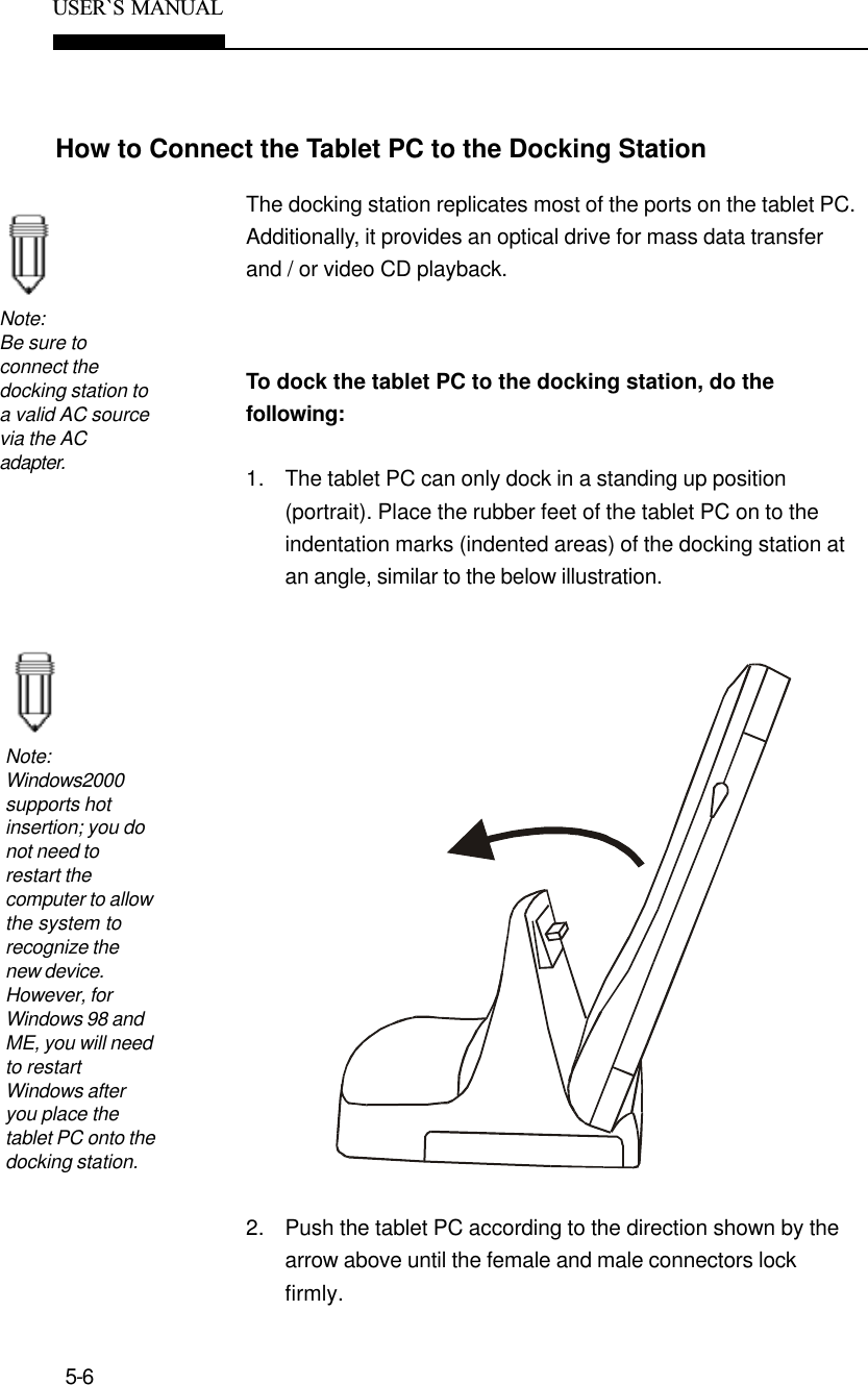
![2-6USER`S MANUALThe built-in USB camera allows you to take a snap shot andrecord it onto the hard disk drive.To capture a picture using Windows Imaging, do the follow-ing1. Go to [Start > Programs > Accessories > Imaging] to startthe Imaging application.2. Go to [File > Acquire Image...] to launch the camera’s utilitysoftware.3. The following diagram appears. You may need to adjust thefocus ring for the sharpest image.Note:Digital Camera](https://usermanual.wiki/ViewSonic/VSVPD10000203/User-Guide-233988-Page-23.png)
![Section 2 Using Software2-9Modem SettingThe built-in modem allows you to dial-up Internet or send a fax.Depending on where your computer is used, you may need tochange settings in the modem. Correct setting will allow you tomaintain a stable connection in a country where its telecommuni-cation system may be different to others.To change the modem setting, do the following:1. Go to [Start > Settings > Control Panel] and double-click onModem Settings icon. You will see the following dialog box.2. Click on the pull-down manu and select the country where itis applicable. Click on OK to exit.](https://usermanual.wiki/ViewSonic/VSVPD10000203/User-Guide-233988-Page-26.png)
![2-10USER`S MANUALVirtual KeyboardBecause the tablet PC uses a touch-sensitive screen, it allowsyou to enter text quickly by using the virtual keyboard.To activate the virtual keyboard, do the following:Double-click on the Virtual Keyboard icon on the desktop orat the lower right-hand corner of the task bar. (If you do nothave short-cut icon on your desktop, the application can befound in the factory`s CD-ROM disk. [d:\utility\VirtualKeyboard\VirtualKeyboard.exe])To exit the virtual keyboard, do the following:Click on the Virtual Keyboard icon at the task bar`s rightcorner and select Exit.](https://usermanual.wiki/ViewSonic/VSVPD10000203/User-Guide-233988-Page-27.png)
![2-12USER`S MANUALWorking Without KeyboardThere are occasions when OS requires to press the Ctrl-Alt-Delete keys such as when Windows2000 boots up.To disable the Secure Boot Ctrl-Alt-Delete requirement, dothe following:1. Go to [Start > Settings > Control Panel] and double-click onUsers and Passwords icon.2. Go to the Advanced tab and do not check off “Require usersto press Ctrl-Alt-Delete...”3. Press OK to exit.](https://usermanual.wiki/ViewSonic/VSVPD10000203/User-Guide-233988-Page-29.png)
![Section 2 Using Software2-13Automatic RebootThe system allows automatic rebooting when system locks up.To enable automatic reboot, do the following:1. Go to [Start > Settings > Control Panel] and double-click onthe System icon.2. Go to the Advanced tab and click on Startup and Recovery.3. Put a check on Automatically reboot and press OK to exit.](https://usermanual.wiki/ViewSonic/VSVPD10000203/User-Guide-233988-Page-30.png)
![2-14USER`S MANUALStandby Resume SecurityIf you enable the Windows` Standby Resume Security function,you will be prompted to enter a password with a mechanicalkeyboard after the computer wakes up from the suspend state.To disable standby resume password prompt, do thefollowing:1. Go to [Start > Settings > Control Panel] and double-click onthe Power Options icon. Click on the Advanced tab.2. Leave the `Prompt for password...` field unchecked. PressOK to exit.](https://usermanual.wiki/ViewSonic/VSVPD10000203/User-Guide-233988-Page-31.png)

![3-6USER`S MANUALUsing Windows Power OptionsNote:When runningon battery, try torefrain fromopening toomany applica-tions at once.In the Windows Power Options Properties (Start > Settings >Control Panel > Power Options) dialogue boxes, you may entertime-out values for display and hard disk drive. Windows powermanager saves power by turning off hard drive after 1 minute ofinactivities, for example. The following section will describe howto make use of the power saving feature.Power SchemesGo to [Start > Settings > Control Panel] and double-click onPower Options icon.In this dialog box, you can manually set the LCD and hard drive`stime-out values in the Plugged in column and in the Running onbatteries column. Lower time-out values will save more batterypower.Note:Also consultWindows userguide for moreinformation on howto use Windowspower manage-ment functions.](https://usermanual.wiki/ViewSonic/VSVPD10000203/User-Guide-233988-Page-37.png)
![3-8USER`S MANUALPower Button ActionNote:Do not install orremove thememory modulewhen the system isin the suspendmode.The tablet PC`s power button can be set to turn off the system oractivate the suspend mode.Go to [Start > Settings > Control Panel > Power Options] andclick on the Advanced tab. In the pull-down manu, select how youwish the power button to work as.](https://usermanual.wiki/ViewSonic/VSVPD10000203/User-Guide-233988-Page-39.png)
![6-4USER`S MANUALAudio ProblemsNo speaker output -nSoftware volume control is turned down in Microsoft SoundSystem. Double-click the speaker icon on the lower rightcorner of the taskbar to see if the speaker has been muted.nMost audio problems are software-related. If your computerworked before, chances are software may have been setincorrectly.nGo to [Start > Settings > Control Panel] and double-clickthe Multimedia icon (or Sounds and Multimedia icon). In theAudio page, make sure that SiS 7018 Wave is the preferredplayback device.Sound can not be recorded -nDouble-click the speaker icon on the lower right corner ofthe taskbar to see if the microphone has been muted.1. Click Options and select Properties. 2. Select Recording and click the OK button. 3. After Click OK button, the recording volume control panelwill appear.nGo to [Start > Settings > Control Panel] and double-click theMultimedia icon (or Sounds and Multimedia icon). In theAudio page, make sure that SiS 7018 Wave is the preferredrecording device.](https://usermanual.wiki/ViewSonic/VSVPD10000203/User-Guide-233988-Page-57.png)
![6-6USER`S MANUALThe hard disk takes longer to read a file -nIf you have been using the drive for a period, the files maybe fragmented. Go to [Start > Programs > Accessories >System Tools > Disk Defragmenter] to perform a diskdefragment. This operation may take a while.The files are corrupted -nRun the ScanDisk surface scan to check the platter. (Thisfunction is available in Windows. Go to [Start > Programs >Accessories > System Tools > ScanDisk] to perform a disksurface scan. This operation may take a while.CD-ROM or DVD-ROM ProblemsThe CD-ROM or DVD-ROM drive of the docking station doesnot work -nTry rebooting the system.nThe disk is damaged or files are not readable.nAfter you have inserted a CD-ROM disk, it may take amoment before you can access its content.The drive dose not read any disks -nThe CD may not be properly seated in the tray. Makesurethe disk is firmly seated onto the spindle.nThe disk is damaged or not readable.The disk can not be ejected -nNormally, it takes a few seconds to eject the disk.nIf the disk can not be ejected, it may be mechanicallyjammed. Straighten out a paper clip and insert it to a tinyhole next to the eject button. This should reject the disk tray.If not, return the unit for repair.](https://usermanual.wiki/ViewSonic/VSVPD10000203/User-Guide-233988-Page-59.png)
![Section 6 TROUBLE SHOOTING6-7Display ProblemsThe display panel is blank when the system is turned on -nMake sure the notebook is not in the suspend mode. Thedisplay is turned off to conserve energy in these modes.nUse the brightness control utility to increase the screenbrightness.The screen is difficult to read -nUse the brightness control utility to increase the screenbrightness.nThe display resolution should be set to 1024x768 for optimalviewing.1. Go to [Start > Settings > Control Panel] and double-clickon the Display icon.2. Under the Settings page, click the Adanced icon.3. Under the Dispaly Modes page to set the resolution to1024x768 and choose at least 256 colors.The screen flickers -nIt is normal if the display flickers a few times during shuttingdown or powering up.](https://usermanual.wiki/ViewSonic/VSVPD10000203/User-Guide-233988-Page-60.png)
![Section 6 TROUBLE SHOOTING6-9The characters on the screen repeat while I type.nYou may be holding the keys down too long while you`retyping.nKeep the keyboard clean. Dust and dirt under the keyscould cause them to stick.nConfigure the keyboard to wait longer before the autorepeat feature starts. To adjust this feature, Go to [Start >Settings > Control Panel], and double-click on the Keyboardicon. A dialogue box shows up with the adjustable settingsfor the keyboard.CMOS ProblemA message “CMOS Checksum Failure” displays during thebooting process -nIf the message “CMOS Checksum Failure” appears duringthe booting procedure, it may indicate failure of the CMOSbattery. Return the computer to the dealer for service.](https://usermanual.wiki/ViewSonic/VSVPD10000203/User-Guide-233988-Page-62.png)
![Section 6 TROUBLE SHOOTING6-11Modem ProblemsThe built-in modem does not respond -nMake sure the modem driver is loaded properly.Go to [Start > Settings > Control Panel > Modem] and makesure HAMR 56 or SmartRiser56 Voice Modem is listed in theModems Property page. Otherwise, click the Add button toadd the modem drive, which is located in the factory CD-ROM (or floppy diskette).nGo to [Start > Settings > Control Panel > System] and in theDevice Manager page check for possible resource or driverconflict. See Windows on-line help or manual for how tohandle such problems.nMake sure the phone line the computer is connected to isworking.Connection difficulties -nBe sure to disable Call Waiting.nExcessive line noise might cause the connection to bedropped. To check this, put the regular phone handset on theline and placing a phone call. If you do hear abnormal noise,try to make the modem connection with a different line orcontact your local telephony company for service.nMake sure the RJ-11 cable (the one that goes from themodem to the telephone line) is firmly connected to themodem's RJ-11 jack and the telephone line socket.nCheck the serial port settings. Make sure the hardware andsoftware are referring to the same COM port.nCheck the communications parameters (baud rate, parity,data length and stop bits) specified in the communicationsprogram.nTry a different receiver number and see if the problempersists.nBe sure the line has a dial tone.](https://usermanual.wiki/ViewSonic/VSVPD10000203/User-Guide-233988-Page-64.png)
![6-12USER`S MANUALNetwork Adapter ProblemsThe Ethernet adapter does not work –nGo to [Start > Settings > Control Panel] and double click theSystem icon. Select the Device Manager tab from theSystem Properties. Double-click on Network Adapters andcheck if SiS 900 PCI Fast Ethernet Adapter appears as oneof the adapters. If it does not exist, Windows has notdetected the SiS adapter or the device driver has not beeninstalled. If there is a yellow mark or red cross on the SiSnetwork adapter, there may be a device or resource conflict.Consult Windows manual on how to solve this problem.nMake sure the physical connections on both ends of thecable are good.nThe hub or concentrator may not be working properly. Checkto see if other workstations connected to the same hub orconcentrator are working.The Ethernet adapter does not appear to operate in the100Mbps transmission mode –nMake sure the hub you are using supports 100Mbpsoperation.nMake sure that your RJ-45 cable meets the 100Base-TXrequirements.nMake sure the Ethernet cable is connected to the hub‘ssocket that supports 100Base-TX mode. The hub may haveboth 100Base-TX and 100Base-T sockets.PC Cards do not function-nMake sure you have properly installed the driver for the card.nConsult the card`s manual or contact the vendor for trouble-shooting.PC Card (PCMCIA) Problems](https://usermanual.wiki/ViewSonic/VSVPD10000203/User-Guide-233988-Page-65.png)