ViewSonic VSVPD10000203 Wireless View Pad User Manual 520sec1
ViewSonic Corporation Wireless View Pad 520sec1
Revised Manual

Section 1 GETTING TO KNOW THE BASICS
1-1
SECTION 1
GETTING TO KNOW THE BASICS
This section introduces the features and compo-
nents of the tablet PC.

1-2
USER`S MANUAL
Performance Features
n
High Performance Processor
The tablet PC is equipped with Intel Celeron proces-
sor with 128K L2 cache.
n
Advanced Graphic Engine
An integrated AGP-bus 2D/3D video processor for
high performance graphics. The video chip also
incorporates a hardware-accelerated playback which
gives you smooth MPEG video playback. 3D graphics
capability also adds realism to PC games.
n
Upgradability *
The system offers additional DRAM slot for expansion,
allowing users to easily increase the system capacity
as the need arises.
n
Bright LCD Display
The sytem is equipped with 10.4-inch TFT XGA
display panel for clear text and brilliant colors.
n
Portrait Mode or Landscape Mode
To serve your specific needs, the tablet PC can be
used in Portrait or Landscape mode.
n
Touch Screen Input
The tablet PC has a built-in touch screen input device.
This allows you to easily and quickly maneuver and
create graphic designs or manage field applications.
Note:
Hard disk drive is
not user-
upgradable. If you
need to upgrade the
HDD, you need to
return the unit to the
dealer or
manufacturer.

■
Audio Capability
The system is equipped with internal audio and record and
playback functions, including 3D (three-dimensional) audio,
64-voices DirectSound channel support, and built-in
hardware wave-table.
■
Ethernet Adapter and Modem
The system provides built-in Ethernet network adapter
and 56K modem for communiction and connection
flexibility.
■
Built-in Digital Camera
The integrated digital camera allows you to take
snapshots or record a video clip.
■
Wireless LAN
The computer may be equipped with Wireless LAN (802.11) to
connect to a wireless network.
■
Docking Station (Optional)
The optional docking station not only provides all the
necessary I/O ports, it also has a built-in CD-ROM or
DVD-ROM for large data access or video disk
playback.
1-3
Section 1 GETTING TO KNOW THE BASICS
1-4
USER`S MANUAL
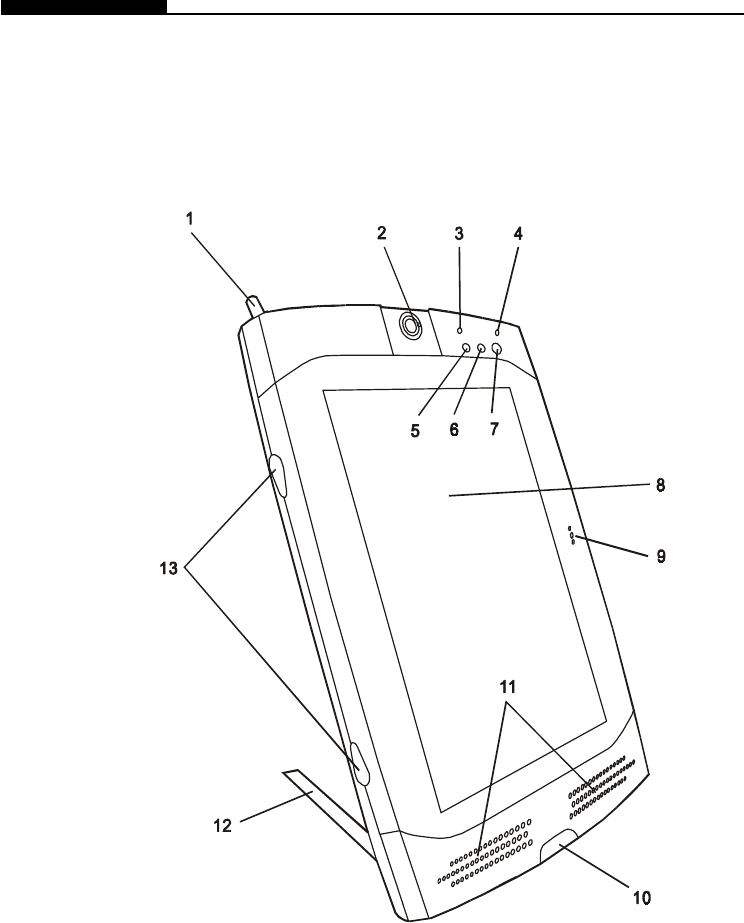
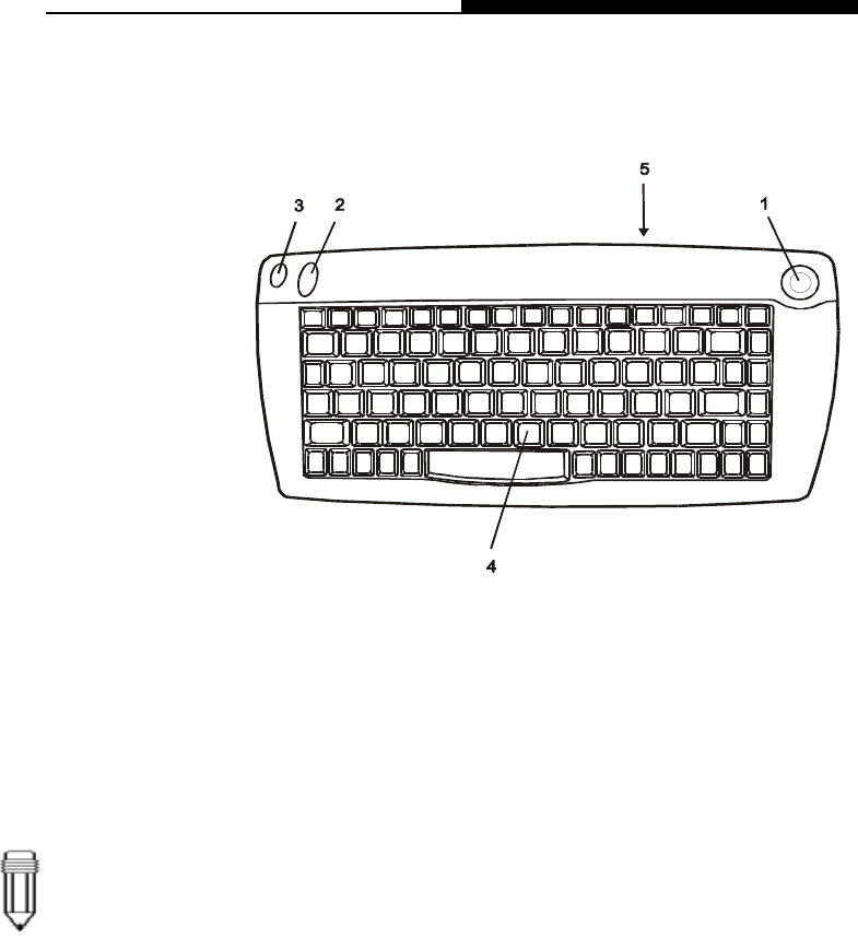
1. Stylus
The stylus (touch pen) works like a mouse. Use the tip to
point to an icon on the LCD panel or draw a line in any
graphic application. Tapping an icon twice in a quick session
is similar to double-clicking with a mouse.
System at a Glance
Front View

Section 1 GETTING TO KNOW THE BASICS
1-5
2. Ditigal Camera
The built-in digital camera (up to 640x480 resolution) allows
you to take photos or record a video clip. You must pre-
install software that will work with the camera. See Factory
CD-ROM disk for any bundled graphic software. The focus
ring allows you to adjust focal length of the camera lens.
Adjust the ring to for the sharpest focus. Go to
How to Use
the Digital Camera
Section for more details.
3. Battery Status LED
Flashing green light indicates the battery pack is being
charged.... (See the
LED Status Indicator
Section for
details.)
4. Power Status LED
The multi-color LED indicates the power status of the tablet
PC. (See the
LED Status Indicator
Section for details.)
5. WWW Internet Hot Key
The `Internet Hot Key` launches the Internet Explore
automatically. You will need to activate a utility program in
the factory CD to make use of the key. (See side-note for
Quick Keys installation.)
6. Email Hot Key
The `Internet Hot Key` launches the MS Outlook Express.
You will need to activate a utility program in the factory CD
to make use of the key. (See side-note for Quick Keys
installation.)
7. Power/Suspend Button
The power/suspend button turns the system on and off and it
also acts as a system suspend key. This tablet PC uses a
special one-button design. Press momentarily to turn on the
system. Press and hold for at least 3~4 seconds to turn off
the system. In Windows 98 SE, ME, or 2000, how the
power button should behave can be defined in Windows
Power Management utility. Go to [Start > Settings > Control
1-6
USER`S MANUAL
Panel > Power Management] to access the utility. Go to
Section 2 for more details on system suspend function.
8. LCD Display
The panel is where the system`s data is displayed.
9. Built-in Microphone
The built-in microphone records sound.
10. Consumer Infrared Port (1)
The CIR port is used to link with a CIR-type wireless
keyboard.
11.Built-in Stereo Speakers
The built-in speakers output the sound in stereo.
12. Stand
The stand allows the tablet PC to be positioned vertically
(Portrait Mode) or horizontally (Landscape Mode) on a
desktop.
13. Rubber Feet
The rubber feet allows the tablet PC to be positioned on its
side on the desk.
Note:
If you encounter
difficulties with
IrDA (infrared port)
operation, go to
Section 5 to learn to
solve the problems.
Warning:
Do not place any
heavy objects on
the LCD panel. It
may damage the
display.
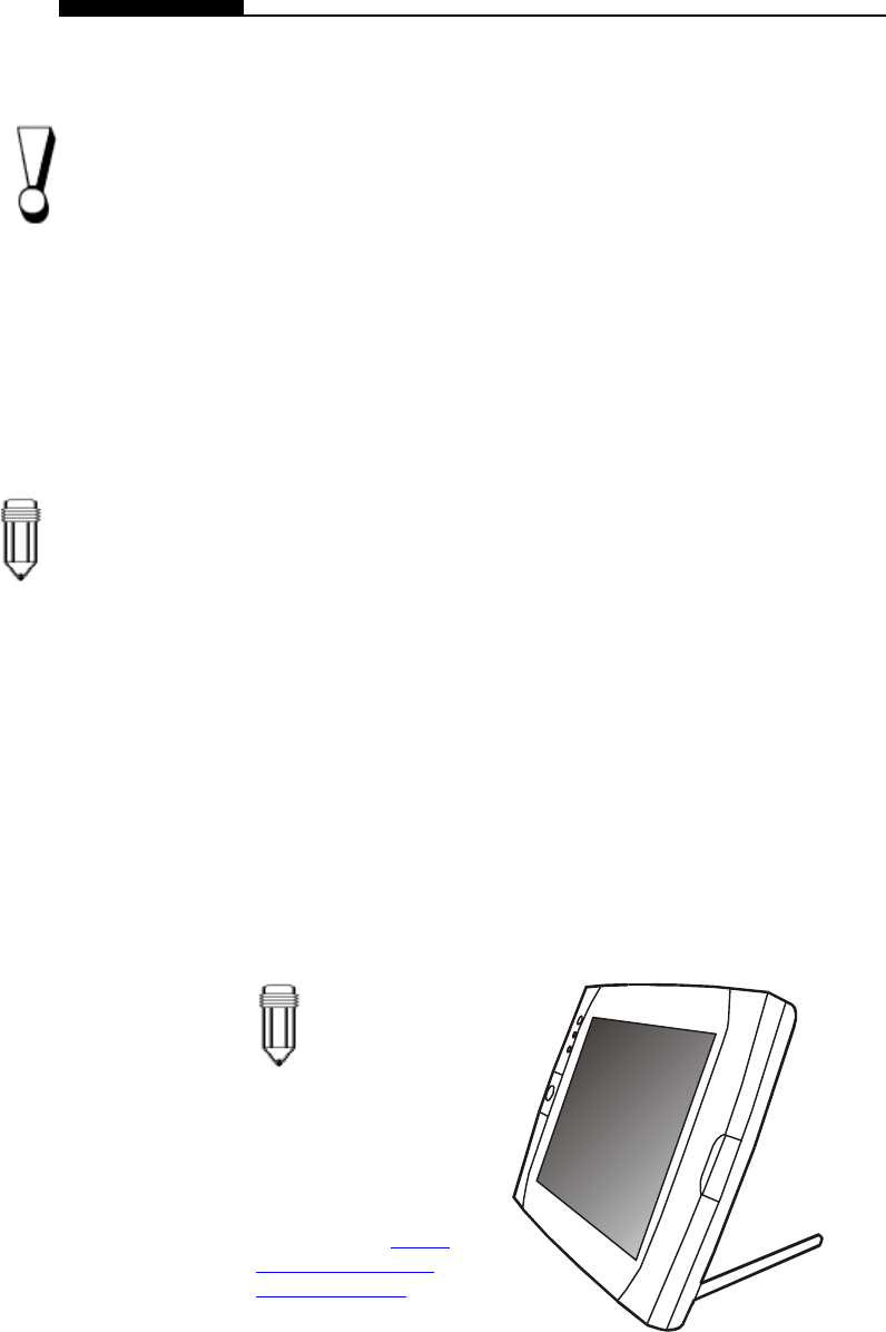
Note:
The tablet PC can be
positioned horizontally.
You will need to rotate
the display content 90
degrees via the `Pivot`
software. Go to How to
Use the Tablet PC in
Landscape Mode Section
to learn more.
Section 1 GETTING TO KNOW THE BASICS
1-7
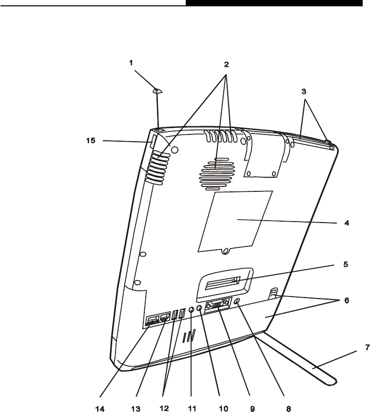
1. Built-in Antenna
The antenna is used to transmit and receive data from
another Bluetooth-enabled device / system. It should be fully
extended for best result. Go to the Bluetooth Help Menu for
operational tips. (
The Bluetooth application is contained in
the Factory CD-ROM disk.
)
2. Ventilation Grills
The fan grills allow the air to circulate through the internal
heat regulation system. Do not block the airway completely.
Rear View

1-8
USER`S MANUAL
3. PC Card Slot (PCMCIA) and Card Eject Button
The slot is where PC Card (PCMCIA) is inserted. Press the
eject button to release the PC Card.
4. DIMM (DRAM) Expansion Slot Cover
This is where two DIMM expansion slots are located. One
of the slot may have been occupied by a dealer or manu-
facturer pre-installed DIMM module.
5. Docking Port
The docking port allows the tablet PC to connect to an
optional docking station. Go to Chapter 5 for more details
on the docking station.
6. Battery Pack and Battery Latch
The battery pack is a built-in power source for the tablet
PC. Pull on the battery latch to release the battery pack.
7. Stand
The stand allows the tablet PC to be positioned vertically
(Portrait Mode) or horizontally (Landscape Mode) on a
desktop.
8. Power Jack ( DC-in )
This is where the AC Adapter connects to. It allows the
external AC source to power the system and charges its
battery pack.
9. External VGA Port
The 15-pin analog VGA output port connects to the external
CRT monitor or projector.
10. Stereo Headphone Jack
The stereo headphone jack (3.5-mm diameter) is where you
connect the headphones or external speakers.
11. Microphone Jack
The microphone jack (3.5-mm diameter) is where you
connect a microphone.
Note:
For the system
running the
Windows NT
platform,USB
function was not
supported.

Section 1 GETTING TO KNOW THE BASICS
1-9
12. USB Port
The Universal Serial Bus (USB) port allows you to connect a
wide variety of devices via the USB cable to your tablet PC.
This port conforms to USB plug-and-play standards.
13. Modem Port
This is where you plug the phone jack (RJ-11) for fax/
modem functions. The built-in 56kpbs modem is V.90
compatible.
14. Ethernet / LAN Port
The port connects to a network hub via the RJ-45 cable and
also conforms to 100Base-TX transmission protocol.
15. Serial Infrared Port (2)
The SIR port is an Infrared Data Association (IrDA) compli-
ant serial infrared port. It allows cableless data transfer with
IrDA 1.1-compatible external devices.
1-10
USER`S MANUAL
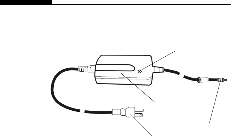
AC Adapter
1. DC-In Connector
The DC-out connector docks to the power jack on the tablet
PC.
2. LED Lamp
The LED lamp appears green when the unit is plugged into a
valid AC source.
3. Adapter
The adapter converts alternating current into constant
voltage for the tablet PC.
4. AC Plug
The three-prong AC plug plugs to the AC wall outlet.
4
1
2
3
Section 1 GETTING TO KNOW THE BASICS
1-11
1. Mouse Pointer
Move the mouse pointer just as you would with a mouse or
touch pad.
2. Left Click Button
This button works like the left button of a mouse.
3. Right Click Button
This button works like the right button of a mouse.
4. Keyboard
The enhanced 87/88-key keyboard is used to enter data. It
has an embedded numeric keypad and cursor control keys.
5. CIR Lens
The IR lens transmits keyboard and cursor input via infrared
beam.
KeyBoard Features
Note:
Point the CIR
Lens of the
keyboard
straight toward
Consumer
Infrared Port of
the tablet PC.
The effective
range is a few
meters.
1-12
USER`S MANUAL
Num Lock Enables the embedded keypad to work in
numeric mode. The keys act like numeric
keypads in a calculator. Use this mode
when you need to do a lot of numeric data
entry. An alternative would be to connect an
external numeric keypad.
Scroll Lock Press the ScrLk key and then press ¡ôor ¡õ
to move one line up or down.
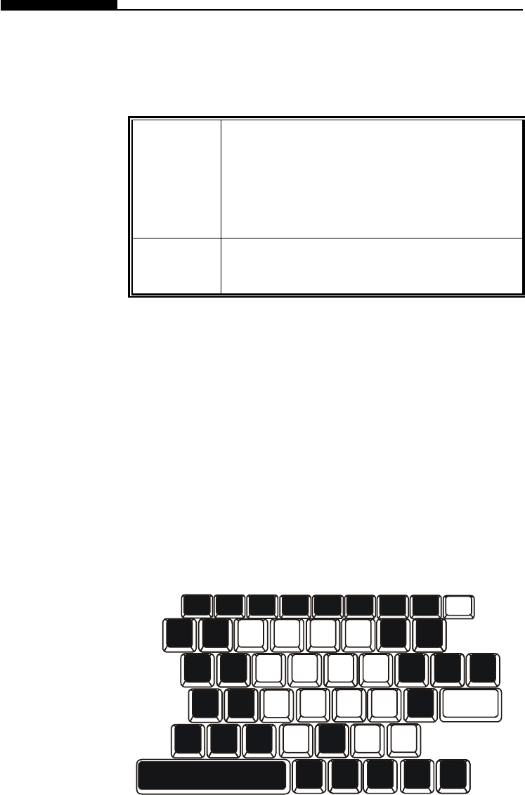
Embedded Numeric Key Pad
Press Num Lock to enable the embedded numeric key pad. The
numbers are printed in upper right corner of a key, in a color
different from the alphabets. This key pad is complete with
arithmetic operators (+, -, * , /).
Press Num Lock to revert to normal character keys.
Function (Hot) Keys
123
456
789
0
_
+
*
/
Enter
.
Num
Lock
Section 1 GETTING TO KNOW THE BASICS
1-13
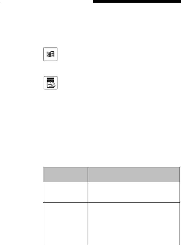
Windows Keys
Your keyboard also has two Windows keys:
1. Start Key
This key allows you to pull up the Windows Start
Menu at the bottom of the taskbar.
2. Application Menu Key
This key brings up the popup menu for the
application, similar to a click of the right mouse
botton.
LED Graphic
Symbol Indication
Orange light indicates the battery is
being charged.
Green light indicates the computer is ON.
Blinking green light indicates the HDD is
being accessed.
Orange light indicates the system is now
in suspend mode.
LED Status Indicators
The LED Status Indicator displays the operating status of your
tablet PC. When a certain function is enabled, a LED will light up
or flash intermittently. The following section describes its
indication.

1-14
USER`S MANUAL
Display
Adjusting the Display Brightness
Note:
To maximize
your battery
operating
time, set the
brightness to
the lowest
comfortable
setting, so that
the internal
back-light
uses less p
ower.
Extending the Life of the TFT Display Device
Your tablet PC uses a high performance 10.4-inch active matrix
TFT panel which supports high resolution and multi-million colors
for comfortable viewing. A powerful 2D / 3D integrated graphic
chipset is used for fast graphic performance.
.
The tablet PC uses a special utility software to control
brightness. See Section 2 for instructions.
Observe the following guidelines to maximize the life of the back-
light in the display.
1. Set the brightness to the lowest comfortable setting.
2. Do not disable the suspend time-outs.
3. If you are using AC power and have no external monitor
attached, change to suspend mode when not in use.

Section 1 GETTING TO KNOW THE BASICS
1-15
Audio Devices
Adjusting the Volume in Windows
Voice Recording
The Audio in your tablet PC is Sound Blaster Pro-compatible.
1. Click the speaker symbol in the taskbar in Windows.
2. Drag the volume control bar up or down to adjust the
volume.
3. To temporarily silence the speaker without changing the
volume setting, click Mute.
You need to use audio processing software to enable the built-in
microphone. For example, you may use Microsoft Sound
Recorder.
When you begin voice recording using the system`s built-in
microphone, be sure that your mouth is within near distance (no
longer than 20 cm) to the microphone. If the record level is too
small, you may also increase the microphone gain via the volume
control panel in Windows.

1-16
USER`S MANUAL
Modem
Your tablet PC comes with a 56K V.90 internal fax/modem and a
phone jack (RJ-11), which is located on the right side of your
notebook.
Use a telephone cable to connect the notebook to the telephone
wall outlet.
You may need to re-configure the modem setting if you plan to
use it in a different country. Go to Section 2 for instructions on
how to make the adjustment.
Connecting the Modem
1. Plug one end of the phone line into the modem port
located on the back side of the computer.
2. Plug the other end of the line into the analog phone wall
outlet.
Warning:
The internal modem is
intended for use on an
analog phone line, also
called a POTS (Plain Old
Telephone Service) line.
This modem cannot be
connected directly to a
digital telephone line,
such as those commonly
found in a business
office. You may either
obtain an analog line or
an analog converter
compatible with the
phone line you’re using.

Section 1 GETTING TO KNOW THE BASICS
1-17
Network Adapter
Your tablet PC is equipped with a 100Base-TX Ethernet network
adapter. Connecting the active LAN cable to the RJ-45 LAN port
located in the back of the system. This allows you to access and
transmit data in the local area network.
Connecting to the Network
Use Unshielded Twisted Pair (UTP) Ethernet cable only.
1. Insert one end of the UTP cable into the network con-
nector until the connector snaps securely into the
receptacle.
2. Either connect the other end of the cable to an RJ-45
jack wall outlet or to an RJ-45 port on a UTP concentra-
tor or hub in the network.
Cabling Restriction for Networks
The following restrictions should be observed for 100BASE-TX
networks:
nThe maximum cable run length is 100 meters(m) (328 feet
[ft]).
nFor 100-Mbps operation, use Category 5 wiring and
connections.
Consult Windows manual and / or Novell Netware user‘s guide for
the software installation, configuration, operation of the network.

Section 2 Using Software
2-1
SECTION 2
USING SOFTWARE
In this section, you will learn how to use the software
functions of various hardware devices so that you can
work more effectively on your tablet PC.

2-2
USER`S MANUAL
The tablet PC has many unique capabilities such as touch-
sensitive screen, built-in digital camera, vitual keyboard, etc.
However, some of these devices may require you to perform a
one-time setup to enable it to work accurately.
Traditionally, a standard keyboard is built into a PC. However,
due to the lack of a permanently attached keyboard input device,
the tablet PC may require you perform certain adjustment to the
Windows operating system.
Throughout this manual, we will assume that you are using
Windows 2000 has the tablet PC’s operating system.
Section 2 Using Software
2-3
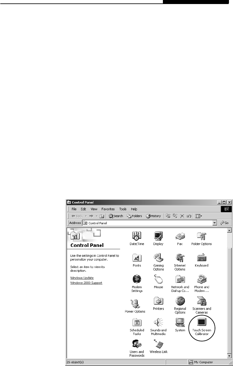
Touch Screen Calibration
Although touch screen calibration may have already been
performed at the factory, there are times that it needs to be re-
calibration for higher accuracy.
The touch screen is a touch-sensitive device. It is a membrane
on top of the LCD display. It responds to mechanical pressure on
the screen surface. You can navigate the cursor using the stylus
(pen). When you notice the stylus tip does not correspond well
or match point-to-point with the cursor, you then need to re-
calibrate the touch screen device.
To calibrate the touch screen, do the following:
1. To go [Start > Settings > Control Panel] and double-click on
Touch Screen Calibrator icon.
2-4
USER`S MANUAL
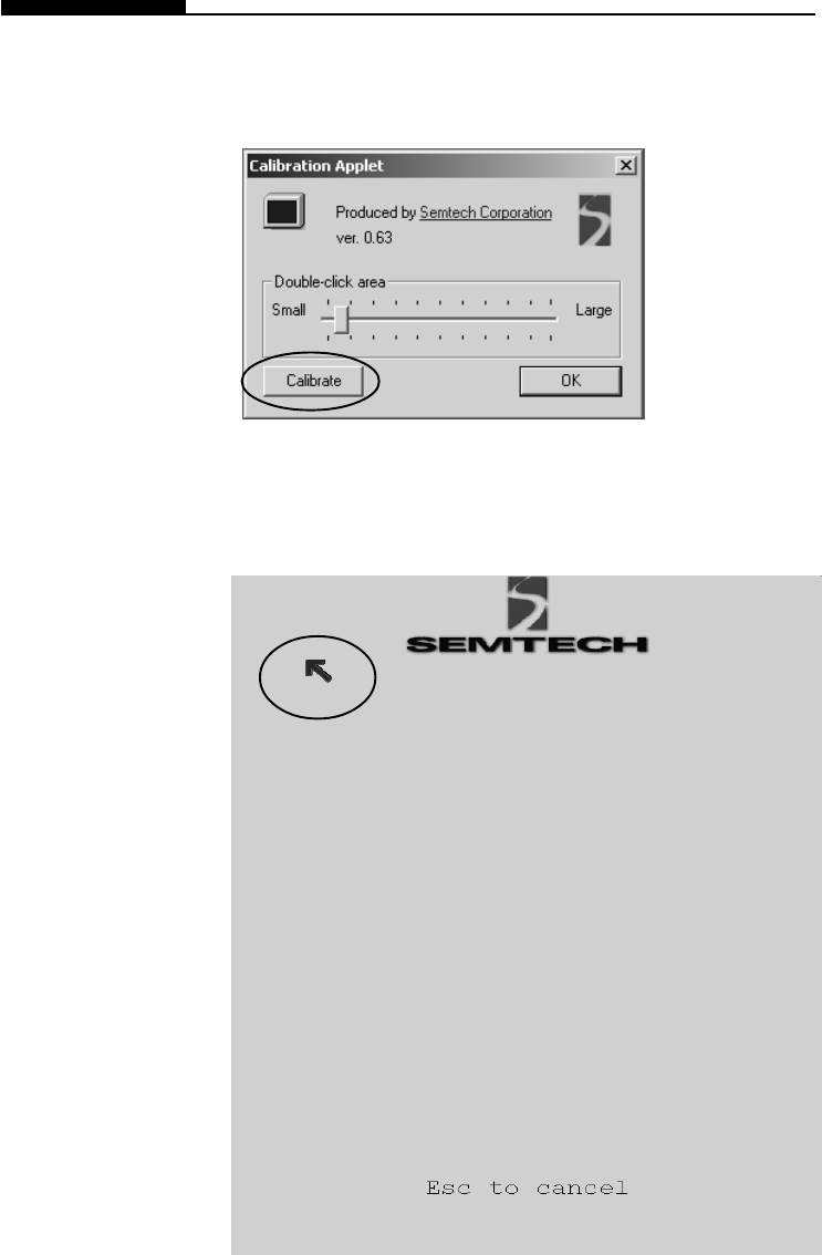
2. You will see the following dialogue box.
3. Click on Calibrate button and you will see the following
display.

Section 2 Using Software
2-5
4. Use the stylus to point accurately to the tip of the red arrow
on the display. Start by the upper left corner of the display
and you will be asked to repeat the pointing action 4 times.
5. If you wish to change to a larger double click area, you may
do so at the Calibration Applet box by moving up the slider.
(See diagram to the left.) Click on OK to exit the applet.
Note:
The calibration
effect takes
place immedi-
ately after you
exit the applet.
2-6
USER`S MANUAL
The built-in USB camera allows you to take a snap shot and
record it onto the hard disk drive.
To capture a picture using Windows Imaging, do the follow-
ing
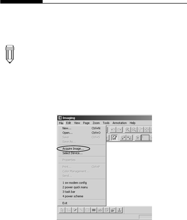
1. Go to [Start > Programs > Accessories > Imaging] to start
the Imaging application.
2. Go to [File > Acquire Image...] to launch the camera’s utility
software.
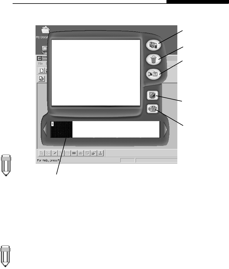
3. The following diagram appears. You may need to adjust the
focus ring for the sharpest image.
Note:
Digital Camera
Section 2 Using Software
2-7
4. Click the camera icon on the right to take a snapshot. The
shot you have just taken will be displayed on the bottom row.
5. Select an image in the bottom row by clicking on the image.
You will see red outlining to indicate the particular frame has
been selected for transfer.
6. Click on the Exit and Transfer icon to exit the applet and
transfer the selected image to Windows Imaging application.
Tip on photographing: Always use the best lighting possible.
To take a snapshot
To delete a picture
Note:
If you do not
select an
image in the
bottom row, no
image will be
transferred.
Note:
To change the
resolution
setting, click on
the Adjust
Camera
Resolution icon
shown above.
Image is displayed here.
To exit and transfer
the selected image
to the photo-editing
To adjust camera
To adjust camera hue,
Selected image to be
transferred is high-
lighted by the red
2-8
USER`S MANUAL
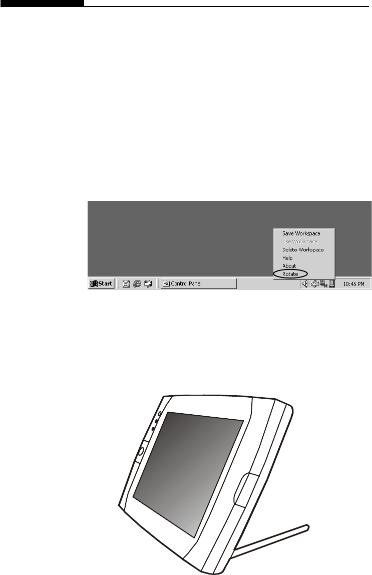
Screen Rotation
A special application - Pivot Software - allows you to use the
tablet PC in portrait mode (vertical) or landscape mode
(horizaontal).
To rotate the screen display, do the following:
1. Click the Pivot icon at the right corner of the task bar.
2. Select Rotate to pivot the display 90 degrees.
Repeat steps 1 and 2 to revert to the original mode.
Section 2 Using Software
2-9
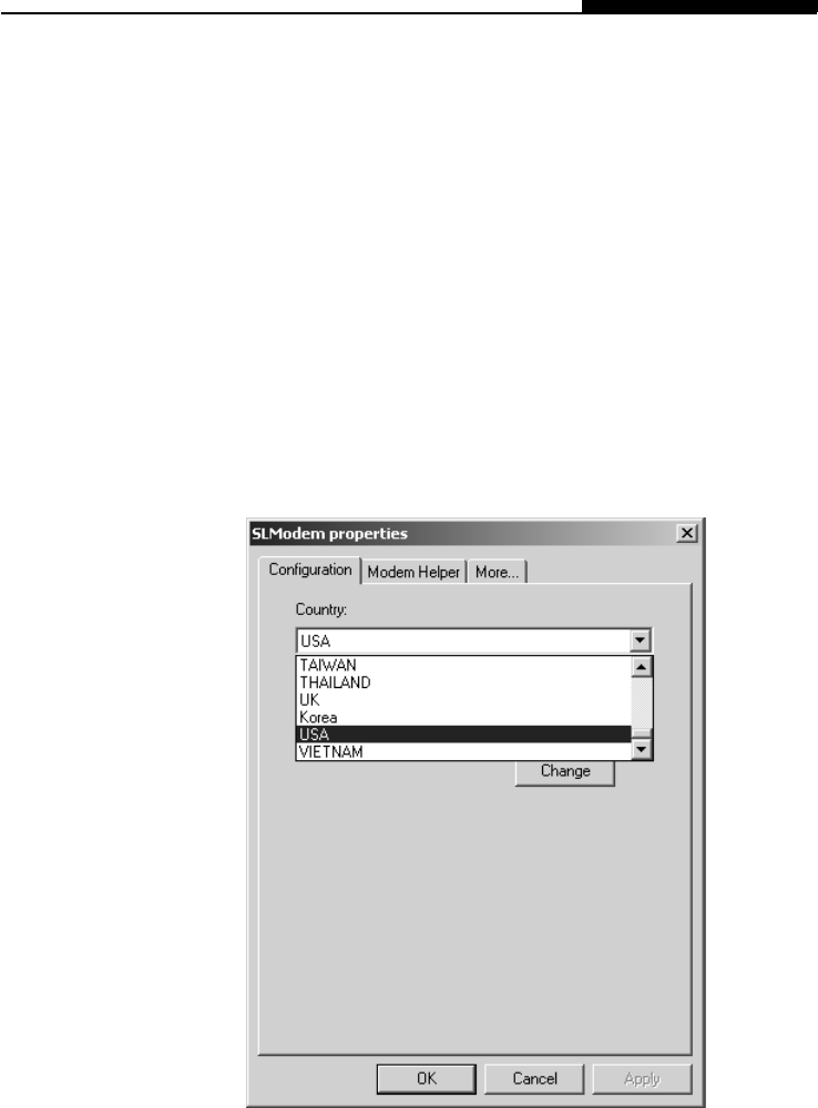
Modem Setting
The built-in modem allows you to dial-up Internet or send a fax.
Depending on where your computer is used, you may need to
change settings in the modem. Correct setting will allow you to
maintain a stable connection in a country where its telecommuni-
cation system may be different to others.
To change the modem setting, do the following:
1. Go to [Start > Settings > Control Panel] and double-click on
Modem Settings icon. You will see the following dialog box.
2. Click on the pull-down manu and select the country where it
is applicable. Click on OK to exit.
2-10
USER`S MANUAL
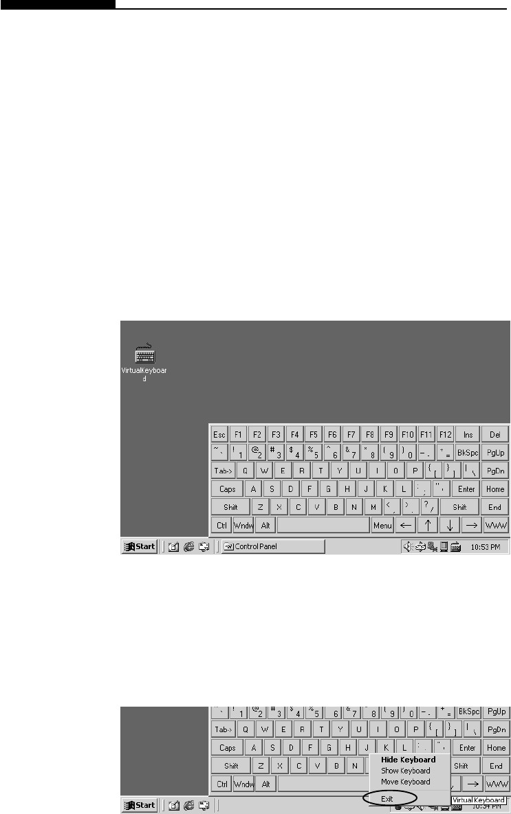
Virtual Keyboard
Because the tablet PC uses a touch-sensitive screen, it allows
you to enter text quickly by using the virtual keyboard.
To activate the virtual keyboard, do the following:
Double-click on the Virtual Keyboard icon on the desktop or
at the lower right-hand corner of the task bar. (If you do not
have short-cut icon on your desktop, the application can be
found in the factory`s CD-ROM disk. [d:\utility\Virtual
Keyboard\VirtualKeyboard.exe])
To exit the virtual keyboard, do the following:
Click on the Virtual Keyboard icon at the task bar`s right
corner and select Exit.
Section 2 Using Software
2-11
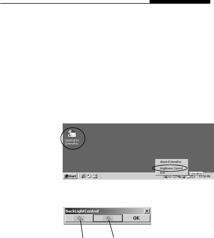
LCD Brightness Control
A utility software is provided to allow you to control the brightness
of the LCD display.
To activate brightness control, do the following:
1. Double-click on the Short Cut to ExtendKey icon or click on
the ExtendKey icon at the right-hand corner of the task bar.
(If you do not see the ExtendKey icon on the desktop, the
application can be found in the factory CD.)
2. Select Brightness Control and the following box appears.
3. Press the Brighter button several times to increase the
brightness or press the Dimmer button to decrease the
brightness. Press OK to exit.
Brighter Dimmer
2-12
USER`S MANUAL
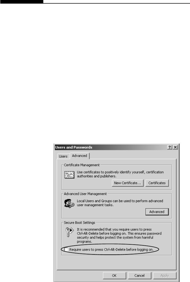
Working Without Keyboard
There are occasions when OS requires to press the Ctrl-Alt-
Delete keys such as when Windows2000 boots up.
To disable the Secure Boot Ctrl-Alt-Delete requirement, do
the following:
1. Go to [Start > Settings > Control Panel] and double-click on
Users and Passwords icon.
2. Go to the Advanced tab and do not check off
“Require users
to press Ctrl-Alt-Delete...”
3. Press OK to exit.
Section 2 Using Software
2-13
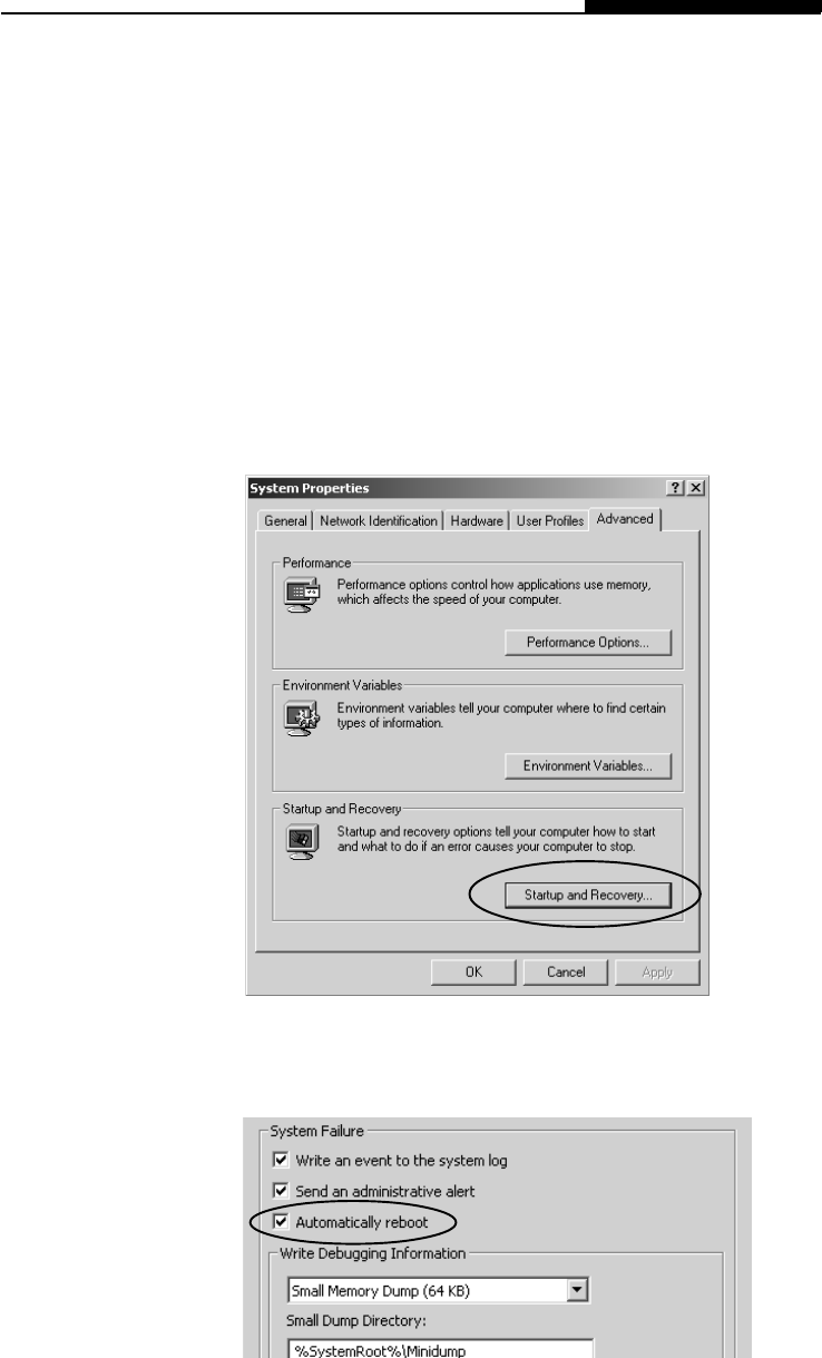
Automatic Reboot
The system allows automatic rebooting when system locks up.
To enable automatic reboot, do the following:
1. Go to [Start > Settings > Control Panel] and double-click on
the System icon.
2. Go to the Advanced tab and click on Startup and Recovery.
3. Put a check on Automatically reboot and press OK to exit.
2-14
USER`S MANUAL
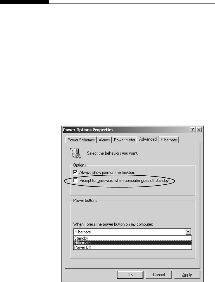
Standby Resume Security
If you enable the Windows` Standby Resume Security function,
you will be prompted to enter a password with a mechanical
keyboard after the computer wakes up from the suspend state.
To disable standby resume password prompt, do the
following:
1. Go to [Start > Settings > Control Panel] and double-click on
the Power Options icon. Click on the Advanced tab.
2. Leave the `Prompt for password...` field unchecked. Press
OK to exit.

Section 3 BATTERY POWER & POWER MANAGEMENT
3-1
SECTION 3
BATTERY POWER AND
POWER MANAGEMENT
In this section, you will learn the fundamentals of power
management and how to achieve longer battery life.

3-2
USER`S MANUAL
The Battery Pack
Note: Make sure the
battery is fully
charged before
using.
Note: In the Standby
suspend mode, a
fully charged battery
loses its power in
roughly 1/2 ~ 1 day.
When kept in
storage, the battery`s
power will deplete in
1-2 month.
Note: Do not touch
the metal ends of the
battery connector.
Warning:
Do not expose
battery packs to
temperatures below
0 degree Celsius (32
degree F) or above
60 degree C (140F).
This may adversely
affect the battery
pack.
In this section, you will learn how to operate your tablet PC on
battery power, how to handle and maintain the battery pack, and
learn about Windows` power saving features.
TFT display, central processor, hard disk drive are the major
hardware subsystems that consume the most power. Power
management deals how these key components should behave to
conserve power. For example, you can have the system turn off
its display after 2 minutes of inactivity to save power. Efficient
power management can help you work longer sessions before
having to recharge the battery.
When the notebook operates on battery power, the Battery LED
indicator will be on.
Lithium-Ion Battery
Your computer uses an removeable 9-cell Lithium-Ion battery
pack that provides power when you don`t have access to an AC
outlet.
Section 3 BATTERY POWER & POWER MANAGEMENT
3-3
Installing and Removing the Battery Pack
To Detach the Battery Pack:
1. Position the notebook bottom-side up on a flat and
secured surface.
2. Locate the battery latch. Slide the latch to its release
position and hold.
3. While holding the latch, push out the battery’s hard case
and lift it from its recess bay.
To Install the Battery Pack:
1. Position the notebook bottom-side up on a flat and
secured surface.
2. Carefully insert the battery pack into the recess bay until
you hear a click indicating that the battery pack is
locked into its bay.

3-4
USER`S MANUAL
Charging the Battery and Charging Time
Note:
Be sure to reserve
adequate time for
charging before
travelling.
While the battery pack is inserted in the tablet PC, plug the AC
adapter into the notebook and an electrical outlet.
The charging time is approximately 2-3 hours when the computer
is turned off and approximately 6-7 hours when the computer is
turned on.
If your tablet PC is plug into an AC outlet, the battery will still be
trickle-charged even when it is in operation. Charging an empty
battery pack in the trickle-charge mode will take about 6-7 hours
to attain full charge.
When the battery is fully charged, the battery charge indicator
becomes dark (off).

Section 3 BATTERY POWER & POWER MANAGEMENT
3-5
Checking the Battery Level
Prolonging the Battery Pack’s Life and Usage Cycles
Note:
Read Section
Protecting Your
Tablet PC in the
beginning of this
manual for tips
about how to
maintain the
battery pack.
You can check the remaining battery power in the Windows
battery status indicator, which is located at the lower right-hand
corner of the task bar. The accuracy is within +/- 5-7%.
Alternatively, you can access the power meter by clicking the
Power Management icon in the Windows Control Panel.
There are ways you can do to prolong the use of battery.
nUse the AC adapter wherever AC wall outlet is available. This
will ensure uninterrupted computing.
nPurchase additional battery pack.
nStore the battery pack in room temperature. Higher tem-
perature tends to deplete the battery’s power faster.
nMake good use of the power management function. Hiber-
nate suspend mode saves the most energy by storing
current system contents in a hard disk space.
nEven when PC card is not operating, it still draws a small
amount of power. Eject the PC card from the card slot when
not in use.
nThe life expectancy of the battery is approximately 500
recharges.
nSee the notices section in the beginning of the user manual
on how to care for the battery pack.
3-6
USER`S MANUAL
Using Windows Power Options
Note:
When running
on battery, try to
refrain from
opening too
many applica-
tions at once.
In the Windows Power Options Properties (Start > Settings >
Control Panel > Power Options) dialogue boxes, you may enter
time-out values for display and hard disk drive. Windows power
manager saves power by turning off hard drive after 1 minute of
inactivities, for example. The following section will describe how
to make use of the power saving feature.
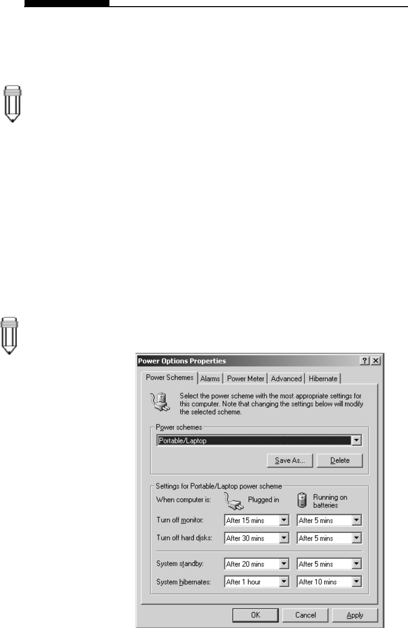
Power Schemes
Go to [Start > Settings > Control Panel] and double-click on
Power Options icon.
In this dialog box, you can manually set the LCD and hard drive`s
time-out values in the Plugged in column and in the Running on
batteries column. Lower time-out values will save more battery
power.
Note:
Also consult
Windows user
guide for more
information on how
to use Windows
power manage-
ment functions.
Section 3 BATTERY POWER & POWER MANAGEMENT
3-7
Suspend Mode
Standby Suspend
The system automatically enters this mode after a period of
inactivity, which is set in the Power Schemes dialog box. In
Standby mode, hardware devices, such as display panel and
hard disk, are turned off to conserve energy.
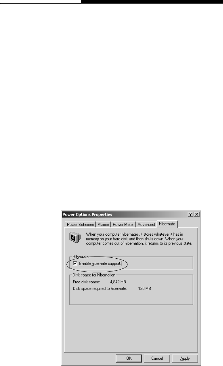
Hibernate Suspend
In this mode, all system data are saved in the hard disk before
powering down. When this mode is activated, all system state
and contents are saved to the hard disk drive after a period of
inactivity defined by the user. No power is drawn from the battery
module under this mode.
However, depending on how much RAM that have been installed
on your notebook, the amount of time the system requires to
restore all its previous contents can range from 5 to 20 seconds.
For Windows ME / 2000 users, hibernation is handled by the
operating system; therefore, no special disk partition or disk file
is necessary.
If you wish to activate Hibernate mode, you need enable Hiber-
nate Support in the Hibernate tab of the Power Options manu.
3-8
USER`S MANUAL
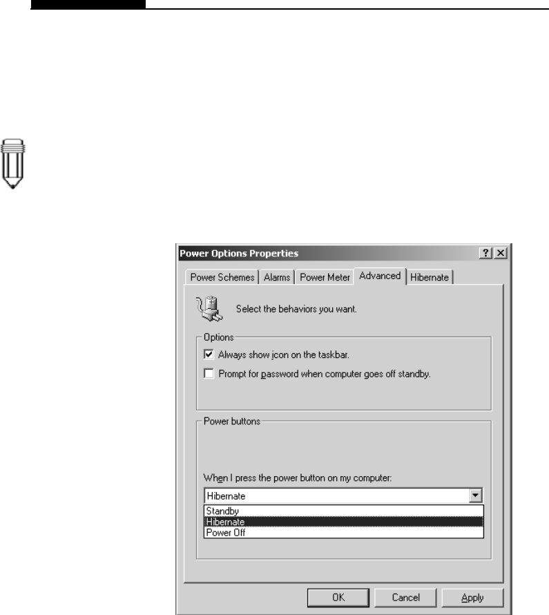
Power Button Action
Note:
Do not install or
remove the
memory module
when the system is
in the suspend
mode.
The tablet PC`s power button can be set to turn off the system or
activate the suspend mode.
Go to [Start > Settings > Control Panel > Power Options] and
click on the Advanced tab. In the pull-down manu, select how you
wish the power button to work as.
Section 3 BATTERY POWER & POWER MANAGEMENT
3-9
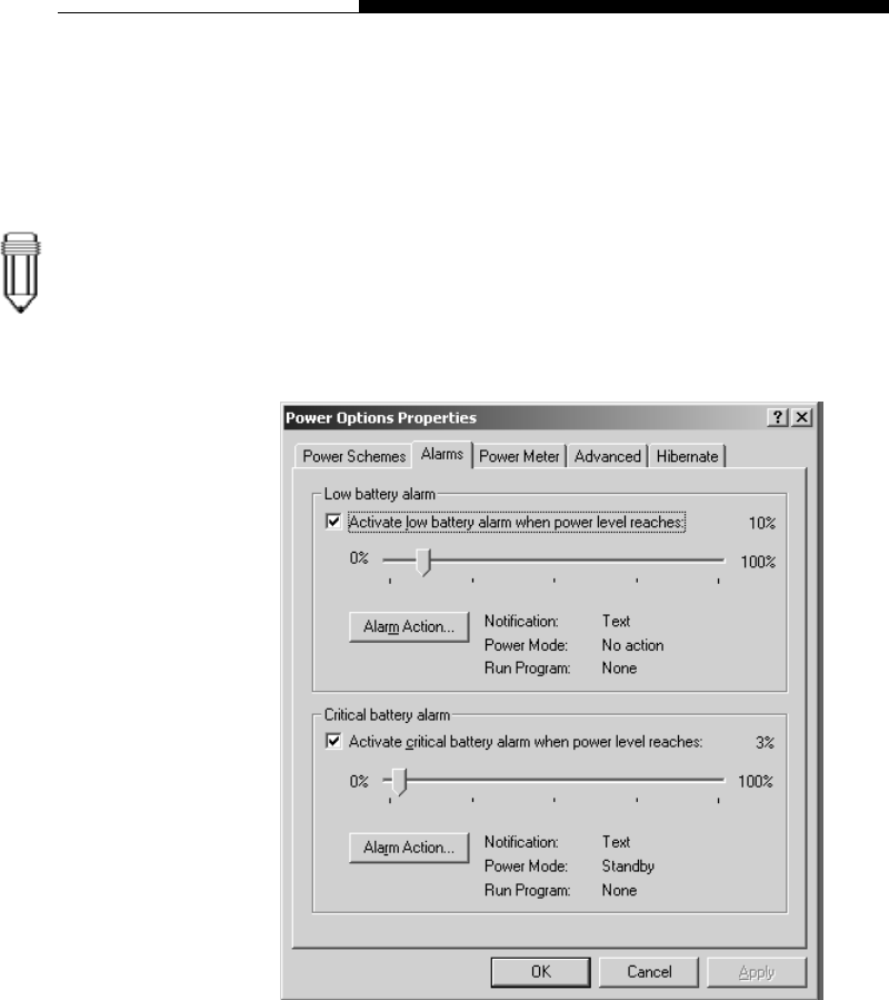
Low Battery Warning
Note:
Consult Windows
user guide for
more information
on how to use
Windows power
management
functions.
You can define when and how the system warns you of its
battery-low condition.
Go to the Alarms tab in the Power Options Properties box. If you
wish to hear audible beeps, click on the Alarm Action button and
put a check on Sound Alarm.
3-10
USER`S MANUAL
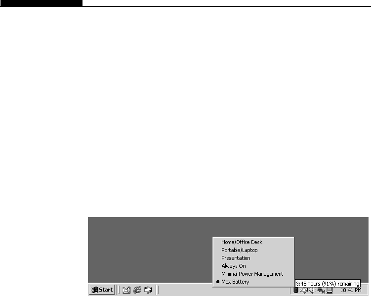
Power Manu Quick Access
In stead of making specific selections in the Power Options
Properties box, you can quickly and easily specify which pre-set
power saving function you desire by clicking on the Battery icon
at the lower right-hand corner of the task bar. (If you do not see
a battery or AC-in icon, go to Power Options Properties box and
click on the Advanced tab. Check off “Always show icon on the
task bar”.) Select Max Battery if you want the system to enter
suspend mode more often. Or, select Always On if your tablet
PC is plugged into an AC power source.

Section 4 UPGRADING YOUR COMPUTER
4-1
SECTION 4
UPGRADING YOUR COMPUTER
In this section, you will learn how to install the
memory module to your tablet PC.

4-2
USER`S MANUAL
Many applications will generally run faster when the system’s
memory capacity is increased. The tablet PC provides two
expansion sockets (usually one slot is already pre-installed by
your dealer or at the factory), located on back side of the
system. You can increase the amount of memory by adding a
dual inline memory module (commonly known as DIMM.) The
DIMM can be 16MB, 32MB, 64MB, 128MB or 256MB in
capacity. The DIMM is of type Synchronous DRAM, has 144 pins
and runs on 3.3V. The speed of the DIMM may be PC100 or
PC133.
Warning: Memory upgrade in this tablet PC is a delicate
process. Please observe the following instructions carefully or
have a qualified technician install it for you. Damages due to
mishandling of this procedure is NOT covered by the
manufacture’s warranty.
Warning: Changing memory while your computer is in suspend or
power-saving mode may cause permanent damage to the tablet
PC. Make sure you turn off the power and unplug the AC cord
before proceeding with a memory upgrade.
Upgrading the System Memory
Section 4 UPGRADING YOUR COMPUTER
4-3
Warning:
To avoid
damaging the
DIMM, do not
touch its metal
contact edge to
avid the electro-
static damage
from static
electricity.
To install a new DIMM, do the following:
1. Power OFF the tablet PC. Unplug the AC cord and all
cables/devices attached to the system.
2. Place your hand on a large metal object momentarily to
discharge any static electricity.
3. Place the tablet PC on a flat surface face-down.
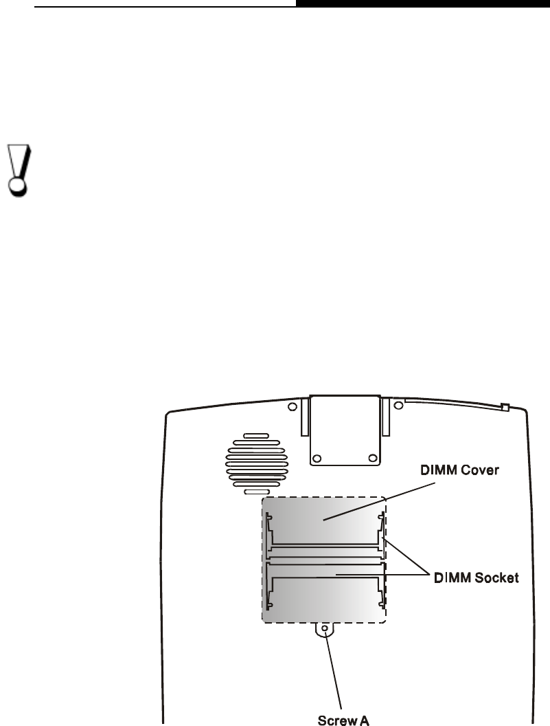
4. Find the DIMM Cover on the back of the computer and
remove Screw A. Lift the DIMM Cover off the computer.
Installing a memory module (DIMM) into the system
4-4
USER`S MANUAL
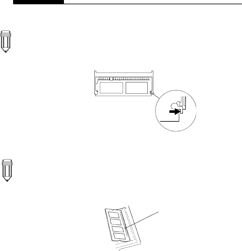
5. If you want to remove an existing DIMM from the socket,
press out on the latches located on both edges of the
socket at the same time. The DIMM should pop up to an
angle of 30 degree (see diagram below.)
6. Pull the DIMM module out of the memory socket. Store
away the DIMM for the future use.
7. Install the new DRAM module into the memory socket.
The DIMM will only fit in one orientation. Insert the DIMM
at an angle of approximately 30 degrees into the empty
memory socket. Then push it firmly so that the contact
edge is driven into the receiving socket.
8. Pivot the DIMM until the latches on both sides of the
socket snap into place. At the time, you will hear a click.
9. Re-attach the DIMM Cover and the screw.
You have now completed the memory upgrade.
Note:
Notice the notch on
the DIMM. The
notch should fit
nicely with the
socket.
Note:
Your computer has
been tested with a
wide range of
DIMM brands on
the market.
However, not all
memory modules
are compatible.
Check with your
vendor for a list of
compatible DIMM
for your tablet PC.
Notch

Section 5 DOCKING STATION
5-1
SECTION 5
DOCKING STATION
In this section, you will learn how to use the tablet PC
with the optional docking station.
5-2
USER`S MANUAL
In this section, you will learn how to use the optional docking
station and to fully take advantage of its functions.
The docking station replicates most of the ports on the tablet PC
and added an optical disk drive (CD-ROM or DVD-ROM) for
mass data transfer or video disk playback.
6
5
4
3
2
1
7
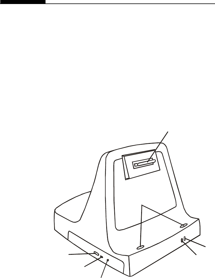
Front View
1. Docking Connector
The receptor connects with the docking connector on the
back side of the tablet PC.
2. Ready To Remove LED Indicator
When the indicator lights up, you can safely remove the
tablet PC from the docking station.

Section 5 DOCKING STATION
5-3
3. AC-in Power Indicator
The LED indicator lights up when the docking station is
connected to an AC power source via the AC adapter.
4. Indentation Mark
The indented areas fit with the rubber feet on the tablet PC.
5. Manual Eject Hole
If the CD-ROM drive is jammed, insert a straightened-out
paper clip or a needle into this hole to manually eject the
CD-ROM disk tray.
6. CD-ROM LED Indicator
The LED indicator lights up momentarily when the drive is
transferring data.
7. Eject Button
Press the eject button to eject the CD-ROM disk tray.
5-4
USER`S MANUAL
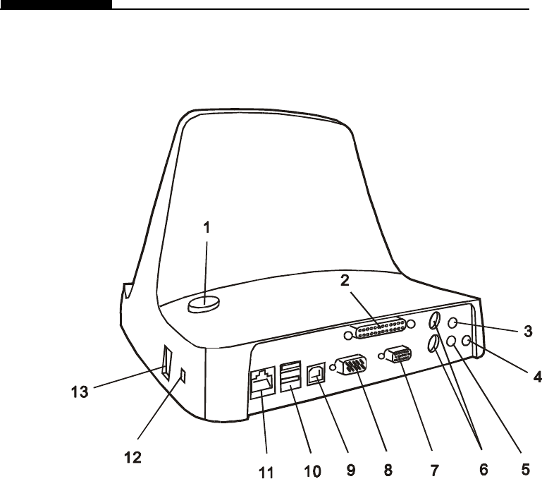
Rear View
1. Eject Button
Press the eject button before removing the tablet PC from
the docking station.
2. Parallel Port
The parallel port is where you connect the printer or any
device using parallel connection.
3. Microphone Jack
The microphone jack (3.5-mm diameter) is where you
connect a microphone.
4. Power Jack ( DC-in )
This is where the AC Adapter connects to. It allows the
external AC source to power the system and charges its
battery pack.

Section 5 DOCKING STATION
5-5
5. Stereo Headphone Jack
The stereo headphone jack (3.5-mm diameter) is where you
connect the headphones or external speakers.
6. PS2 Keyboard / Mouse Port
The PS2 ports allow you to connect to a PS2-type keyboard
and PS2-type mouse.
7. External VGA Port
The 15-pin analog VGA output port connects to the external
CRT monitor or projector.
8. Serial Port
The 9-pin serial port allows you to connect to a serial
modem or any serial-port devices.
9. USB Master
???
10. USB Port
The Universal Serial Bus (USB) ports allow you to connect a
wide variety of devices via the USB cable to your tablet PC.
This ports conform to USB plug-and-play standards.
11. Ethernet / LAN Port
The port connects to a network hub via the RJ-45 cable and
also conforms to 100Base-TX transmission protocol.
12. Kensington Lock Key Hole
A Kensington-type security lock latches to this key-hole for
anti-theft purpose.
13. Modem Port
This is where you plug the phone jack (RJ-11) for fax/
modem functions. The built-in 56kpbs modem is V.90
compatible.
5-6
USER`S MANUAL
How to Connect the Tablet PC to the Docking Station
Note:
Be sure to
connect the
docking station to
a valid AC source
via the AC
adapter.
The docking station replicates most of the ports on the tablet PC.
Additionally, it provides an optical drive for mass data transfer
and / or video CD playback.
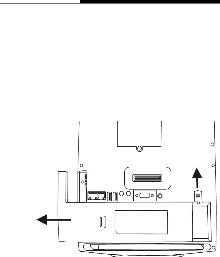
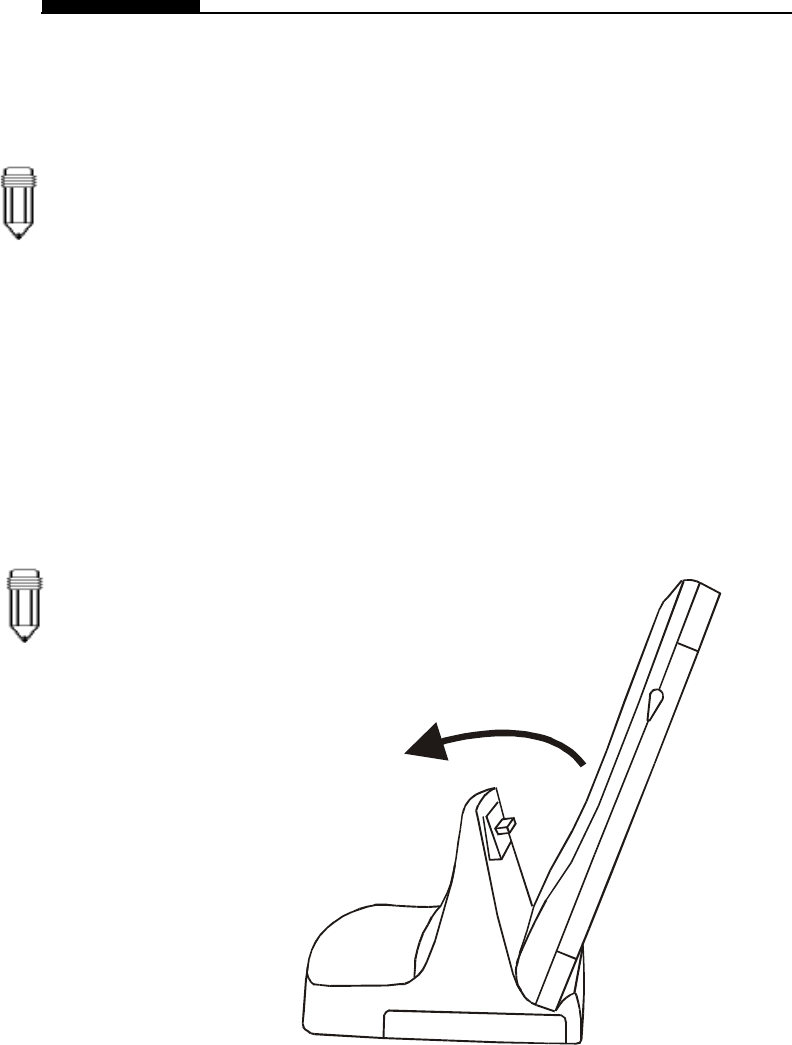
To dock the tablet PC to the docking station, do the
following:
1. The tablet PC can only dock in a standing up position
(portrait). Place the rubber feet of the tablet PC on to the
indentation marks (indented areas) of the docking station at
an angle, similar to the below illustration.
2. Push the tablet PC according to the direction shown by the
arrow above until the female and male connectors lock
firmly.
Note:
Windows2000
supports hot
insertion; you do
not need to
restart the
computer to allow
the system to
recognize the
new device.
However, for
Windows 98 and
ME, you will need
to restart
Windows after
you place the
tablet PC onto the
docking station.

Section 5 DOCKING STATION
5-7
Once you have successfully completed the docking sequence,
you can access My Computer in Windows and verify that a CD-
ROM drive or DVD-ROM drive is present. Also, if you double-click
on the Unplug or Eject Hardware icon at the right-hand corner of
the task bar, you will see the following message.
Once you have docked the tablet PC onto the docking station, an
internal locking mechanism will prevent you from removing the
tablet PC. This will prevent the system from crashing.
5-8
USER`S MANUAL
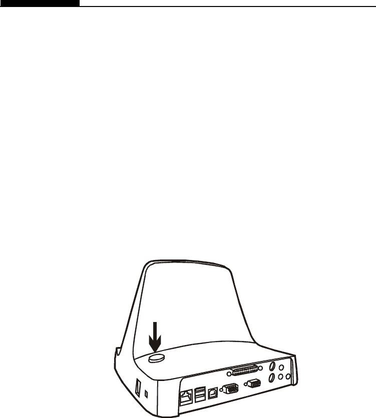
How to Remove the Tablet PC from the Docking Station
To remove the tablet PC from the docking station, do the
following:
1. Press the Eject button on the docking station. In a moment,
the Ready To Remove LED indicator located on the front of
the docking station will light up, indicating it is safe to remove
the tablet PC. The internal locking mechanism will release its
lock and you may hear an audible click. Alternatively, you
can click on the Unplug or Eject Hardware icon at the right-
hand corner of the task bar and Stop the device. A message
will pop up indicating it is safe to remove the tablet PC.

Section 6 TROUBLE SHOOTING
6-1
SECTION 6
TROUBLE SHOOTING
In this section, you will learn how to solve common
hardware and software problems.

6-2
USER`S MANUAL
Your tablet PC has been fully tested and complies with the
system specifications before shipping. However, incorrect
operations and/or mishandling during shipment may cause
problems.
This section provides a reference for identifying and correcting
common hardware and software problems that you may
encounter.
When you encounter a problem, you should first try to go through
the recommendations in this section. Instead of returning the
tablet PC and waiting for repair, you may easily solve the prob-
lems by considering the following problems and possible
solutions. If the error continues, contact your reseller for service
information.
Before taking further actions, consider the following
suggestions:
nCheck to see if the problem persists when all the external
devices are removed.
nCheck to see that the green light indicator on the AC adapter
is lit.
nCheck to see the power cord is properly plugged to the wall
outlet and to the notebook.
nCheck to see the power indicator of the computer is on.
nCheck the brightness control if the LCD display appears
dim.
nCheck to see if your keyboard is operational by pressing and
holding any key.
nCheck for any incorrect or loose cable connections. Make
sure the latches on the connectors latch securely on to the
receptor end.

Section 6 TROUBLE SHOOTING
6-3
nBe sure all the device drivers are installed properly. For
example, without the audio driver properly installed, the
speakers and microphone will not work.
nIf external devices such as scanner, SCSI card do not
function correctly when connected to the system, it may be
the device`s own problem. Consult the device`s
manufacturer.
nSome software programs, which have not gone through
rigorous coding and testing, may cause problems during
your routine use. Consult the software vendor for problem
solving.
nNot all peripheral are plug-and-play capable. You need to
restart the system with these devices powered up and
connected first.

6-4
USER`S MANUAL
Audio Problems
No speaker output -
nSoftware volume control is turned down in Microsoft Sound
System. Double-click the speaker icon on the lower right
corner of the taskbar to see if the speaker has been muted.
nMost audio problems are software-related. If your computer
worked before, chances are software may have been set
incorrectly.
nGo to [Start > Settings > Control Panel] and double-click
the Multimedia icon (or Sounds and Multimedia icon). In the
Audio page, make sure that SiS 7018 Wave is the preferred
playback device.
Sound can not be recorded -
nDouble-click the speaker icon on the lower right corner of
the taskbar to see if the microphone has been muted.
1. Click Options and select Properties.
2. Select Recording and click the OK button.
3. After Click OK button, the recording volume control panel
will appear.
nGo to [Start > Settings > Control Panel] and double-click the
Multimedia icon (or Sounds and Multimedia icon). In the
Audio page, make sure that SiS 7018 Wave is the preferred
recording device.

Section 6 TROUBLE SHOOTING
6-5
Hard Disk Problems
The hard disk drive does not spin -
nCheck the hard disk indicator LED. When you access a file,
the LED lamp should light up momentarily.
nThe HDD may be defective.
nIf your tablet PC has been subjected to static electricity or
physical shock, you may damaged the disk drive.
The hard drive is making abnormal whining noises -
nYou should back up your files as soon as possible.
nMake sure the source of noise if indeed from the hard drive
and not the fan or other devices.
The hard disk drive has reached its capacity -
nDelete backup files or move them to an alternative storage
medium (floppy disk, optical recordable disk, etc.). Many
programs save backup files. You can delete backup files
from the hard disk to create more space for new work.
nArchive files or programs that you had no longer used by
moving them to an alternative storage medium (floppy disk,
optical recordable disk, etc.) or uninstall programs that no
longer use.
nMany browsers store files in the hard drive as a cache to
speed up the performance. Check the program’s Online Help
for instructions on decreasing the cache size or on removing
temporary Internet files.
nEmpty the Recycle Bin to create more disk space. When
you delete files, Windows saves them to the Recycle Bin.

6-6
USER`S MANUAL
The hard disk takes longer to read a file -
nIf you have been using the drive for a period, the files may
be fragmented. Go to [Start > Programs > Accessories >
System Tools > Disk Defragmenter] to perform a disk
defragment. This operation may take a while.
The files are corrupted -
nRun the ScanDisk surface scan to check the platter. (This
function is available in Windows. Go to [Start > Programs >
Accessories > System Tools > ScanDisk] to perform a disk
surface scan. This operation may take a while.
CD-ROM or DVD-ROM Problems
The CD-ROM or DVD-ROM drive of the docking station does
not work -
nTry rebooting the system.
nThe disk is damaged or files are not readable.
nAfter you have inserted a CD-ROM disk, it may take a
moment before you can access its content.
The drive dose not read any disks -
nThe CD may not be properly seated in the tray. Make
surethe disk is firmly seated onto the spindle.
nThe disk is damaged or not readable.
The disk can not be ejected -
nNormally, it takes a few seconds to eject the disk.
nIf the disk can not be ejected, it may be mechanically
jammed. Straighten out a paper clip and insert it to a tiny
hole next to the eject button. This should reject the disk tray.
If not, return the unit for repair.

Section 6 TROUBLE SHOOTING
6-7
Display Problems
The display panel is blank when the system is turned on -
nMake sure the notebook is not in the suspend mode. The
display is turned off to conserve energy in these modes.
nUse the brightness control utility to increase the screen
brightness.
The screen is difficult to read -
nUse the brightness control utility to increase the screen
brightness.
nThe display resolution should be set to 1024x768 for optimal
viewing.
1. Go to [Start > Settings > Control Panel] and double-click
on the Display icon.
2. Under the Settings page, click the Adanced icon.
3. Under the Dispaly Modes page to set the resolution to
1024x768 and choose at least 256 colors.
The screen flickers -
nIt is normal if the display flickers a few times during shutting
down or powering up.

6-8
USER`S MANUAL
Keyboard and Pointing Device (Mouse) Problems
The infrared keyboard accepts no input -
nThis computer is designed to use only one keyboard at once
time. If you are connecting an external USB keyboard to the
system, the infrared keyboard may not work.
nTry restarting the system.
The external PS/2 or serial mouse does not work -
nA special mouse may require a unique driver. Make sure the
driver is properly installed.
nA special external mouse with the thumb-wheel (scroll-
wheel) is not plug-and-playable. In order to enable this
device, you need to have the mouse connected to the P/S2
port before powering up to Windows. Also, you may need to
install the driver, which is specifically designed for this
special type of mouse, to make it work.
The built-in touch screen performs eratically -
nDo not rest your palm or wrist on the surface of the touch
screen while using the stylus.
nIf the membrane on the LCD panel appears broken or
slashed, the touch screen will stop working.

Section 6 TROUBLE SHOOTING
6-9
The characters on the screen repeat while I type.
nYou may be holding the keys down too long while you`re
typing.
nKeep the keyboard clean. Dust and dirt under the keys
could cause them to stick.
nConfigure the keyboard to wait longer before the auto
repeat feature starts. To adjust this feature, Go to [Start >
Settings > Control Panel], and double-click on the Keyboard
icon. A dialogue box shows up with the adjustable settings
for the keyboard.
CMOS Problem
A message “CMOS Checksum Failure” displays during the
booting process -
nIf the message “CMOS Checksum Failure” appears during
the booting procedure, it may indicate failure of the CMOS
battery. Return the computer to the dealer for service.

6-10
USER`S MANUAL
Infrared Problems
The infrared communication port does not work -
n The tablet PC supports standard serial infrared transmission.
It does not support fast IR transmission.
nWindows NT 4.0 does not support infrared devices.
nRemove any objects that sit between the communicating
path.
nMake sure the communicating devices are not more than 1
meter apart and are aligned in a straight-line fashion.
nMake sure that IR device is enabled in the Control Panel. If
the infrared icon at the lower right corner of the task bar has
a red ‘x symbol, it is being disabled. Click on the icon and in
the Option page check off the Infrared Communication item.
Memory Problems
The POST does not show an increased memory capacity
when you have already installed additional memory -
nCertain brands of memory module may not be compatible
with your system. You should ask your vendor for a list of
compatible DIMM.
nThe memory module may not be installed properly. Go back
to Section 4 to review the details of this operation.
nThe memory module may be defective.
The O/S issues an insufficient memory error message during
operation -
nThis is often a software or Windows-related problem.
nClose the application programs you’re not using and restart
the system.
nOtherwise, you have to install additional memory module.
For instructions, go to Section 4
Upgrading Your Computer
.

Section 6 TROUBLE SHOOTING
6-11
Modem Problems
The built-in modem does not respond -
nMake sure the modem driver is loaded properly.
Go to [Start > Settings > Control Panel > Modem] and make
sure HAMR 56 or SmartRiser56 Voice Modem is listed in the
Modems Property page. Otherwise, click the Add button to
add the modem drive, which is located in the factory CD-
ROM (or floppy diskette).
nGo to [Start > Settings > Control Panel > System] and in the
Device Manager page check for possible resource or driver
conflict. See Windows on-line help or manual for how to
handle such problems.
nMake sure the phone line the computer is connected to is
working.
Connection difficulties -
nBe sure to disable Call Waiting.
nExcessive line noise might cause the connection to be
dropped. To check this, put the regular phone handset on the
line and placing a phone call. If you do hear abnormal noise,
try to make the modem connection with a different line or
contact your local telephony company for service.
nMake sure the RJ-11 cable (the one that goes from the
modem to the telephone line) is firmly connected to the
modem's RJ-11 jack and the telephone line socket.
nCheck the serial port settings. Make sure the hardware and
software are referring to the same COM port.
nCheck the communications parameters (baud rate, parity,
data length and stop bits) specified in the communications
program.
nTry a different receiver number and see if the problem
persists.
nBe sure the line has a dial tone.

6-12
USER`S MANUAL
Network Adapter Problems
The Ethernet adapter does not work –
nGo to [Start > Settings > Control Panel] and double click the
System icon. Select the Device Manager tab from the
System Properties. Double-click on Network Adapters and
check if SiS 900 PCI Fast Ethernet Adapter appears as one
of the adapters. If it does not exist, Windows has not
detected the SiS adapter or the device driver has not been
installed. If there is a yellow mark or red cross on the SiS
network adapter, there may be a device or resource conflict.
Consult Windows manual on how to solve this problem.
nMake sure the physical connections on both ends of the
cable are good.
nThe hub or concentrator may not be working properly. Check
to see if other workstations connected to the same hub or
concentrator are working.
The Ethernet adapter does not appear to operate in the
100Mbps transmission mode –
nMake sure the hub you are using supports 100Mbps
operation.
nMake sure that your RJ-45 cable meets the 100Base-TX
requirements.
nMake sure the Ethernet cable is connected to the hub‘s
socket that supports 100Base-TX mode. The hub may have
both 100Base-TX and 100Base-T sockets.
PC Cards do not function-
nMake sure you have properly installed the driver for the card.
nConsult the card`s manual or contact the vendor for trouble-
shooting.
PC Card (PCMCIA) Problems

Section 6 TROUBLE SHOOTING
6-13
Performance Problems
The PC card can not be recognized -
nWindows NT4.0 does not support PCMCIA (PC Card)
function. You may need an external program for this.
nMake sure the card is fully inserted; the outer end of the
card should be even with the edge of the computer.
nRemove and insert the PC card again.
nMake sure there is no IRQ conflict with the card. See
Windows on-line help for solving IRQ conflicts.
nReboot the computer and see if the problem persists.
nThe card may be defective. Try the card on another system,
if possible.
Windows crashes or freezes when you remove the PC card-
nMake sure you have <Stop> the PC card before removing it.
Click on the PC card icon at the lower right corner of the
task bar and select the card you wish to stop. When you
click <OK>, in few seconds Windows will prompt you to
remove the card.
The computer becomes hot -
nIn a 35oC environment, the computer’s bottom case is
expected to reach 50 degrees.
nMake sure the air vents are not blocked.
nIf the fan does not seem to be working at high temperature
(50 degrees Celsius and up), contact the service center.
nCertain programs that are processor-intensive may increase
the computer`s temperature to a degree where the computer
automatically slows down its CPU clock to protect itself
from thermal damage.
The program appears stopped or runs very slowly -
nRestart the system.
nThis may be normal for Windows when it is processing other
CPU-intensive programs in the background.

6-14
USER`S MANUAL
Power, Start, and Battery Problems
nYou may be running too many applications. Try to close
some applications or increase system memory for higher
performance.
nThe processor may have overheated due to the system`s
inability to regulate its internal heat. Make sure the tablet
PC`s ventilation grills are not blocked.
The computer powers down as soon as it is powered on -
nBattery power may be extremely low. The circuitry prevents
a complete power drain, which is not intended for Lithium Ion
batteries. Use the adapter to charge it for several hours
before trying again.
The computer beeps intermittently -
nWhen battery charge is critically low, an audible beep warns
you. Go to Section 3 to learn to disable the alarm.
The battery life gets shorter and shorter -
nThe battery has a finite life of about 500 charge cycles. If
your battery is over one or two years old, it may be time to
have it replaced.
nTry a higher power saving setting in the Windows Power
Options.
The battery does not charge -
nMake sure the AC adapter is plugged into a valid power
source.
nThe battery charge indicator LED on the computer should be
lit when you plug in the AC adapter.
nMake sure the battery module is fully inserted in its bay;
make sure the battery latch is in locked position.
nIf the battery is operating at a very high temperature, it may
not charge.

Section 6 TROUBLE SHOOTING
6-15
Printing Problems
The printer does not print -
nMake sure the cable connection is secured and the printer
is powered up.
nRun the printer self test to see if it reports any problem.
nCheck if the printer displays any error messages. A paper
jam may have occurred.
nMake sure you have already installed the printer driver.
nMost printer (using parallel or serial port) problems are
software-related. Consult Windows on-line help or contact
the printer vendor for assistance.
nTry rebooting the system with the printer powered up and
connected first.
The printer does not print what`s on the screen -
nThe information displayed on the screen may not exactly be
the same as what is printed.
nIf the printer print extra and strange symbols, it is the result
of the cache (garbage) in the printer momery buffer. Call off
all the printer task and toggle off the printer power switch to
clear up the momery buffer. Then, trun the printer back
online and print again.
nMake sure you install the correct printer driver.
The printer does not respond to infrared communication -
nSee Infrared Problems listed elsewhere in this section.

6-16
USER`S MANUAL
Parallel, USB Problems
The Parallel Port does not work -
nMake sure the cable is fully connected.
nThe parallel-port devices may not
be plug-and-play
capable.
Reboot the computer with the devices powered up and
connected first.
The USB device does not work -
nWindows NT 4.0 does not support USB protocols
nCheck the settings in the Windows Control Panel.
nMake sure you have installed the necessary device drivers.
nContact the device vendor for additional support.

Appendix A PRODUCT SPECIFICATION
A-1
APPENDIX A
PRODUCT SPECIFICATION

A-2
USER`S MANUAL
Intel Celeron processor
micro PGA package
32KB (16KB for Code Instruction, 16KB for Data) on-die
128KB on-die
SiS630S chipset with graphic, audio, modem, and Ethernet
controller integrated
66 /100/133 MHz Front Side (Memory) Bus
AGP Bus
Processor and Core Logic
• Processor
• L1 Cache
• L2 Cache
• Core logic
• Bus
Architecture
Synchronous DRAM, PC100 / PC133 compatible
32MB / 64MB, 3.3-Volt 64-bit bus
Total of Two 144-pin SO-DIMM sockets
System Memory
• Memory Type
• Defualt
• Memory
Expanssion
10.4-inch SVGA active-matrix TFT display with up to 16M colors
LCD
• Display Panel
SiS 630S with integrated AGP bus 2D / 3D graphics accelerator
UltraAGP architecture graphics capability (similar to 4X AGP),
3D Graphics Supported
Motion Compression and IDCT Supported for DVD Playback
Simultaneous LCD / External Monitor Display
Dual Independent LCD and External Monitor Display Supported
Share-memory architecture with up to 50% of the total system
memory and/or up to 32MB
Direct3D compatible,
DirectX 6.0 compatible,
VESA DDC1, DDC2B & DDC 3.0 supported.
Graphics
• Graphic
Controller
• Graphics
Ability
• Playback
• Multimonitor
Display
• Memory
Sharing
• Other
Features

Appendix A PRODUCT SPECIFICATION
A-3
SiS 630S with integrated PCI Fast Ethernet function for
100Base-TX network standards.
Windows 95 / 98 / ME / 2000 Plug and Play compatible
Automatic Jam and auto-negotiation for flow control
Auto Negotiation and Parallel detection for automatic speed
selection (IEEE 802.3u)
High performance 32-bit PCI bus master architecture with
integrated DMA controller for low CPU and bus utilization.
Remote Wake-up Scheme supported
Hot Insertion supported
LAN
• Network
Adapter
• PnP Function
• Flow Control
• Speed
Seletion
• Other
Features
SiS 630S with Modem Controller integrated
V.90 / K56flex for download data speed up to 56000bps.
V.34, V.17, V.29 protocol supported
Modem
• Chipset
• Transmission
Speed
2.5-inch format (9.5mm height) hard disk drive
Storage Capacity
• Hard Disk
SiS 630S with integrated audio controller
64-voice Polyphony Wavetable Synthesizer
DirectSound 3D accelerator for IID, IAD and Doppler effects
Full duplex, independent sample rate converter
SoundBlaster Pro/16 compatible
AC’97 V2.1 compatible
Full deplex and independent sample rate converter for audio
recording and playback
Audio
• Audio
Chipset
• Sound
Capability

A-4
USER`S MANUAL
One 15-pin CRT connector
One stereo line-out jack & One microphone-in jack
One FIR LED and One CIR-type LED for keyboard
Two USB connectors
One standard phone jack (RJ-11)
One standard network connector (RJ-45)
One DC-in connector
One docking connector for docking station
One internal mini PCI type III A or B slot
Ports
• VGA Port
• Audio Port
• Infrared Port
• USB Port
• Modem Port
• LAN Port
• Power Port
• Docking Port
• mini PCI Slot
Infrared-transmitting (CIR type) 87-key touch-type QWERTY
keyboard with embedded numeric Keypad
4-wire resistive type Touch Screen
CCD, up to 640x480 resolution, manual focus ring, macro lens
support, USB1.0 interface
Other Standard Hardware
• Keyboard
• Pointing
Device
• Digital
Camera
O2Micro OZ 6812 / 6912 controller
Single slot for TYPE I/II
Hot insertion and removal supported
PC Card
• PCMCIA
Controller
• Features
Li-Ion 9-cell, 11.1V, 5400mAh, 60W
Input: 100~240V, 50~60Hz, 1.7A Max @ 115V
Output: 16V, 3.75A, 60W
System OFF: 3.7~4.2 HR (100%)
System ON: 6~6.5 HR (100%)
Low Battery Warning
Suspend / Resume capability
Power
• Main Battery
• AC Adapter
• Recharge
• Other
Features

Appendix A PRODUCT SPECIFICATION
A-5
AMI PnP BIOS
Power On Self Test
DRAM auto-detection, auto-sizing
L2 Cache auto-detection
Hard disk type auto-detection
APM 1.2 (Advanced Power Management) &
ACPI 1.0 (Advanced Configuration Power Interface)
Two Level Password Protection
32bit access, Ultra DMA, PIO5 Mode support
Multi-boot capability
BIOS
• PnP Function
• Self Test
• Auto
Detection
• Power
Management
• Security
• Other
Features
Microsoft Windows 95 / 98 / ME / 2000
Microsoft NT 4.0
Operating System
• O/S
290 (L) x 220 (W) x 26 (H) mm
3.96 lbs / 1.8KG
Operating Temperature: 5 to 35oC (41 to 95oF)
Operating Humidity: 20 to 90 percent RH (5 to 35oC)
Storage Temperature: -20 to 50oC (-4 to 122oF)
Phsical Specification
• Weight
• Environmental
Limitations
Note: Product Specifications are subject to change without notice.n.
Optional Devices
Docking Station
DIMM module
mini PCI card: 2.4GHz Wireless LAN (IEEE802.11b)
2.4GHz Bluetooth Module

A-6
USER`S MANUAL
(L) x (W) x (H) mm
lbs / KG
Operating Temperature: 5 to 35oC (41 to 95oF)
Operating Humidity: 20 to 90 percent RH (5 to 35oC)
Storage Temperature: -20 to 50oC (-4 to 122oF)
• Weight
• Environmental
Limitations
Docking Station
• DVD ROM or
CD-ROM
• PnP Function
• Port
• Button
• LED Indicator
UDMA 66 / IDE-interface, 5.25-inch format (12.7mm height)
Hot insertion support with Windows2000
One 15-pin CRT connector
One stereo line-out jack & One microphone-in jack
One 25-pinparallel connector (ECP / EPP)
One 9-pin serial connector
Two USB connectors
One standard phone jack (RJ-11)
One standard network connector (RJ-45)
One DC-in connector
One docking connector for the tablet PC
One Eject button for system removal
One AC-in Green LED indicator
One Ready-to-Remove Orange LED indicator

Appendix B AGENCY REGULATORY NOTICES
B-1
APPENDIX B
AGENCY REGULATORY NOTICES

B-2
USER`S MANUAL
Federal Communications Commission Notice
This equipment has been tested and found to comply with the limits for a
Class B digital device, pursuant to Part 15 of the FCC Rules. These
limits are designed to provide reasonable protection against harmful
interference in a residential installation. This equipment generates, uses,
and can radiate radio frequency energy and, if not installed and used in
accordance with the instructions, may cause harmful interference to
radio communications. However, there is no guarantee that interference
will not occur in a particular installation. If this equipment does cause
harmful interference to radio or television reception, which can be
determined by turning the equipment off and on, the user is encouraged
to try to correct the interference by one or more of the following
measures:
nReorient or relocate the receiving antenna.
nIncrease the separation between the equipment and the receiver.
nConnect the equipment into an outlet on a circuit different from that
to which the receiver is connected.
nConsult the dealer or an experienced radio or television technician
for help.
Modifications
The FCC requires the user to be notified that any changes or modifica-
tions made to this device that are not expressly approved by the Manu-
facture may void the user’s authority to operate the equipment.
Connections to Peripheral Devices
Connections to this device must be made with shielded cables with
metallic RFI/EMI connector hoods to maintain compliance with FCC
Rules and Regulations.
Declaration of Conformity
This device complies with Part 15 of the FCC Rules. Operation is
subject to the following two conditions: (1) this device may not cause
harmful interference, and (2) this device must accept any interference
received, including interference that may cause undesired operation.
European Notice
Products with the CE Marking comply with both the EMC Directive (89/
336/EEC) and the Low Voltage Directive (73/23/EEC) issued by the
Commission of the European Community.
Compliance with these directives implies conformity to the following
European Norms:
nEN55022 (CISPR 22) Radio Frquency Interference
nEN50082 (IEC801-2, IEC801-3, IEC801-4) Electro-magnetic
Immunity
nEN60950 (IEC950) Product Safety
Canadian Notice
This digital apparatus does not exceed the Class B limits for radio noise
emissions from digital apparatus as set out in the radio interference

Appendix B AGENCY REGULATORY NOTICES
B-3
regulations of the Canadian Department of Communications.
Le present appareil numerique nemet pas de bruits radioelectriques
depassant les limites applicables aux appareils numeriques de
Classe B prescrites dans le reglement sur le brouillage
radioelectrique edicte par le Ministere des Communications du
Canada.
Power Cord Requirement
The power cord supplied with the computer`s AC adapter should
match the plug and voltage requirements for your local area. Regula-
tory approval for the AC adapter has been obtained using the power
cord for the local area. However, if you travel to a different area and
need to connect to a different outlet or voltage, you should use one of
the power cords listed below. To purchase a power cord (including
one for a country not listed below) or a replacement ac adapter,
contact your local dealer.
U.S. and Canada
nThe cord set must be UL-Listed and CSA-Certified.
nThe minimum specifications for the flexible cord are (1) No. 18
AWG, (2) Type SJ, and (3) 3-conductor.
nThe cord set must have a rated current capacity of at least 10 A.
nThe attachment plug must be an earth-grounding type with a
NEMA 5-15P (15A, 125V) or NEMA 6-15P (15 A, 250V)
configuration.
Japan
nAll components of the cord set (cord, connector, and plug) must
bear a `T` mark and registration number in accordance with the
Japanese Dentori Law.
nThe minimum specification for the flexible cord are: (1) 0.75
mm2 conductors, (2) Type VCT or VCTF, and (3) 3-conductor.
nThe cord set must have minimum rated current capacity of 7 A.
nThe attachment plug must be a two-pole, grounded type with a
Japanese Industrial Standard C8303 (15 A, 125 VAC)
configuration.
Other Countries
nThe cord set fittings must bear the certification mark of the
agency responsible for evaluation in a specific country. Accept-
able agencies are:
BSI (UK)
OVE (Australia)
CEBEC (Belgium)
SEMKO (Sweden)
DEMKO (Denmark)
SETI (Finland)
EANSW (Australia)
SEV (Switzerland)
IMQ (Italy)
UTE (France)

B-4
USER`S MANUAL
KEMA (The Netherlands)
VDE (Germany)
NEMKO (Norway)
nThe flexible cord must be of a HAR (harmonized) type HO5VV-F
3-conductor cord with a minimum conductor size of 0.03 square
inches.
nThe cord set must have a current capacity of at least 10 A and a
nominal voltage rating of 125 / 250 VAC.
Battery Safety
nThe battery pack is intended to use only with this computer.
nDo not disassemble the pack.
nDo not dispose of the battery pack in fire or water.
nTo avoid risk of fire, burns, or damage to your battery pack, do
not allow a metal object to touch the battery contacts.
nHandle a damaged or leaking battery with extreme care. If you
come in contact with the electrolyte, wash the exposed area with
soap and water. If it contacts the eye, flush the eye with water for
15 minutes and seek medical attention.
nDo not charge the battery pack if the ambient temperature
exceeds 45oC (113oF).
nTo obtain a replacement battery, contact your local dealer.
nDo not expose the battery pack to high storage temperatures
(above 60oC, 140oF).
nWhen discarding a battery pack, contact your local waste
disposal provider regarding local restrictions on the disposal or
recycling of batteries.
CAUTION: Danger of explosion if battery is incorrectly replaced.
Replace only with same or equivalent type recommended by the
manufacturer. Discard used batteries according to the manufacturer`s
instructions or local laws.
VORSICHT! Explisionsgefahr bei unsachgernazen Austausch der
Batterie. Ersatz nur durch denselben oder einem vom Hersteller
empfohlenem ahnlichen Typ. Entsorgung gebrauchter Batterien navh
Angaben des Herstellers.
CAUTION: MODEL W101S1 FOR USE WITH POWER SUPPLY MODEL
LSE9802A2060 / LSE9901A2070
ATTENTION: MODEL W101S1, POUR UTILISER AVEC LE MODELE
LSE9802A2060 / LSE9901A2070

Appendix B AGENCY REGULATORY NOTICES
B-5
Laser Safety
The CD-ROM drive used with this computer are certified as a Class 1
laser device according to the U.S. Department of Health and Human
Services (DHHS) Radiation Performance Standard and International
Standards IEC 825 / IEC 825-1 (EN60825 / EN60825-1). The device
is not considered harmful, but the following precautions are
recommended:
nDo not open the unit.
nAvoid direct exposure to the laser beam.
nIf the unit requires service, contact an authorized service center.
nEnsure proper use by reading and following the instructions
carefully.
nDo not attempt to make any adjustment of the unit.
CLASS 1 LASER PRODUCT
APPAREIL A LASER DE CLASSE 1
LASERSCHUTZKLASSE 1 PRODUKT
LED (Infrared) Safety
The infrared port located on the left side of this computer is classified
as a Class 1 LED (light-emitting diode) device according to Interna-
tional Standard IEC 825-1 (EN60825-1). This device is not consid-
ered harmful, but the following precautions are recommended:
nDo not attempt to view the infrared LED beam with any type of
optical device.
nDo not attempt to make any adjustment of the unit.
nIf the unit requires service, contact an authorized service center.
nAvoid direct eye exposure to the infrared LED beam. Be aware
that the beam is invisible light and cannot be seen.
CLASS 1 LED PRODUCT
LEDSCHUTZKLASSE 1 PRODUKT

B-6
USER`S MANUAL
CD-ROM warning
Warning! Do not attempt to disassemble the cabinet containing the laser. The
laser beam used in this product is harmful to the eyes. The use of
optical instruments, such as magnifying lenses, with this product
increase the potential hazard to your eyes. For your safety, have this
equipment serviced only by an authorized service provider.
CLASS 1 LASER PRODUCT
LASER KLASSE 1
LUOKAN 1 LASERLAITE
APPAReil A LASER DE CLASSE 1
EN60825-1
Lithium battery warning
This computer contains a lithium battery to power the clock and
calendar circuitry.
CAUTION: Danger of explosion if battery is replaced incorrectly.
Replace only with the same or equivalent type recommended by the
manufacturer. Discard used batteries according to the manufacturer’s
instructions.
ATTENTION: Il y a danger d’explosion s’il y a remplacement incor-
rect de la batterie. Remplacer uniquement avcc unc batterie du
méme type ou d’un type recommandé par le constructer. Mettre au
rébut les batteries usagées conformément aux instructions du
fabricant.
VORSICHT! Explosionsgefahr bei unsachgemäßen Austausch der
Batterie Ersatz nur durch denselben oder einem vom Hersteller
empfohlenem ähnlichen Typ. Entsorgung gebrauchter Batterien nach
Angaben des Herstellers.
Der Arbeitsplatzbezogene Schalldruckpegel nach DIN 45 635 beträgt
70dB (A) oder weniger.
Zum Netzanschluâ dieses Gerätes ist eine geprûfte Leitung zu
verwenden. Fûr einen Nennstrom bis 6A und einem Gerätegewicht
größer 3kg ist eine Leitung nicht leichter als H05VV-F, 3G, 0.75mm2
einzusetzen.
Die Steckdose muß nahe dem Gerät angebracht und leicht
zugänglich sein.