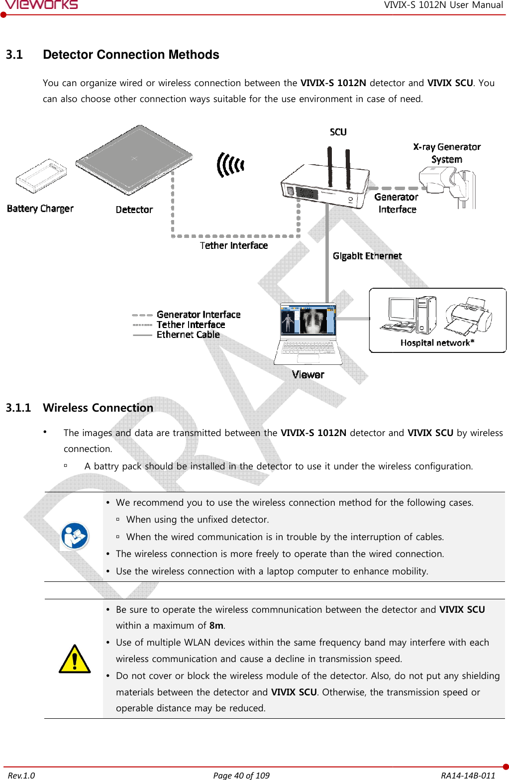
Vieworks FXRD-1012NAW Flat Panel Detector User Manual VIVIX S 1012N V1 0W16 EN
Vieworks Co., Ltd. Flat Panel Detector VIVIX S 1012N V1 0W16 EN
Vieworks >
Contents
- 1. User Manual 1
- 2. User Manual 2
- 3. REVISED Users Manual
User Manual 1
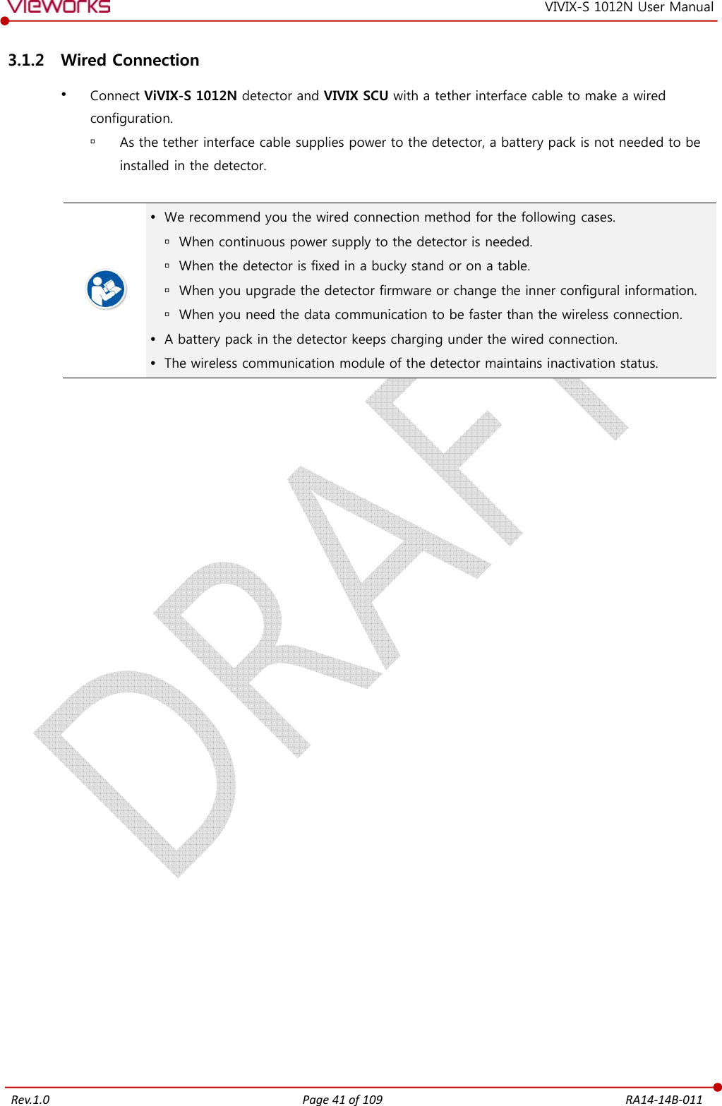
![Rev.1.0 Page 2 of 109 RA14-14B-011 VIVIX-S 1012N User Manual Contents 1. Instruction ......................................................................................................................................... 6 1.1 Document Guide ..................................................................................................................................... 7 1.1.1 Caution Information ..................................................................................................................................................... 7 1.1.2 Target ................................................................................................................................................................................... 7 1.1.3 Symbols .............................................................................................................................................................................. 7 1.1.4 Notations ........................................................................................................................................................................... 8 1.1.5 Contact Department ..................................................................................................................................................... 8 1.2 Product Use Guide .................................................................................................................................. 9 1.2.1 Product Usage ................................................................................................................................................................. 9 1.2.2 Disclaimer .......................................................................................................................................................................... 9 1.2.3 Product Disposal ..........................................................................................................................................................10 1.2.4 Trademarks ......................................................................................................................................................................10 1.3 Safety Instruction .................................................................................................................................. 11 1.3.1 Management and Authority ...................................................................................................................................11 1.3.2 Power Supply .................................................................................................................................................................11 1.3.3 Handling ...........................................................................................................................................................................12 1.3.4 Battery Pack and Charger ........................................................................................................................................13 1.3.5 Environment of Use ....................................................................................................................................................14 1.3.6 Problem Management ...............................................................................................................................................15 1.3.7 Maintenance and Inspection ..................................................................................................................................15 1.4 Product Usage Guide ............................................................................................................................ 16 1.4.1 Calibration .......................................................................................................................................................................16 1.4.2 Length Measurement .................................................................................................................................................16 1.4.3 Left/Right Marker.........................................................................................................................................................16 1.4.4 Image Backup ................................................................................................................................................................16 1.4.5 Use Limitations .............................................................................................................................................................17 1.4.6 Disposal ............................................................................................................................................................................17 1.4.7 Pediatric Application ..................................................................................................................................................17 1.4.8 Before Exposure ............................................................................................................................................................17 1.4.9 During Exposure ...........................................................................................................................................................18 1.4.10 Operating and Storage Environment .................................................................................................................18 1.4.11 Others................................................................................................................................................................................18 2. Product ............................................................................................................................................. 19 2.1 Overview ................................................................................................................................................. 20 2.1.1 Features [TBD] ...............................................................................................................................................20](https://usermanual.wiki/Vieworks/FXRD-1012NAW.User-Manual-1/User-Guide-2532485-Page-3.png)
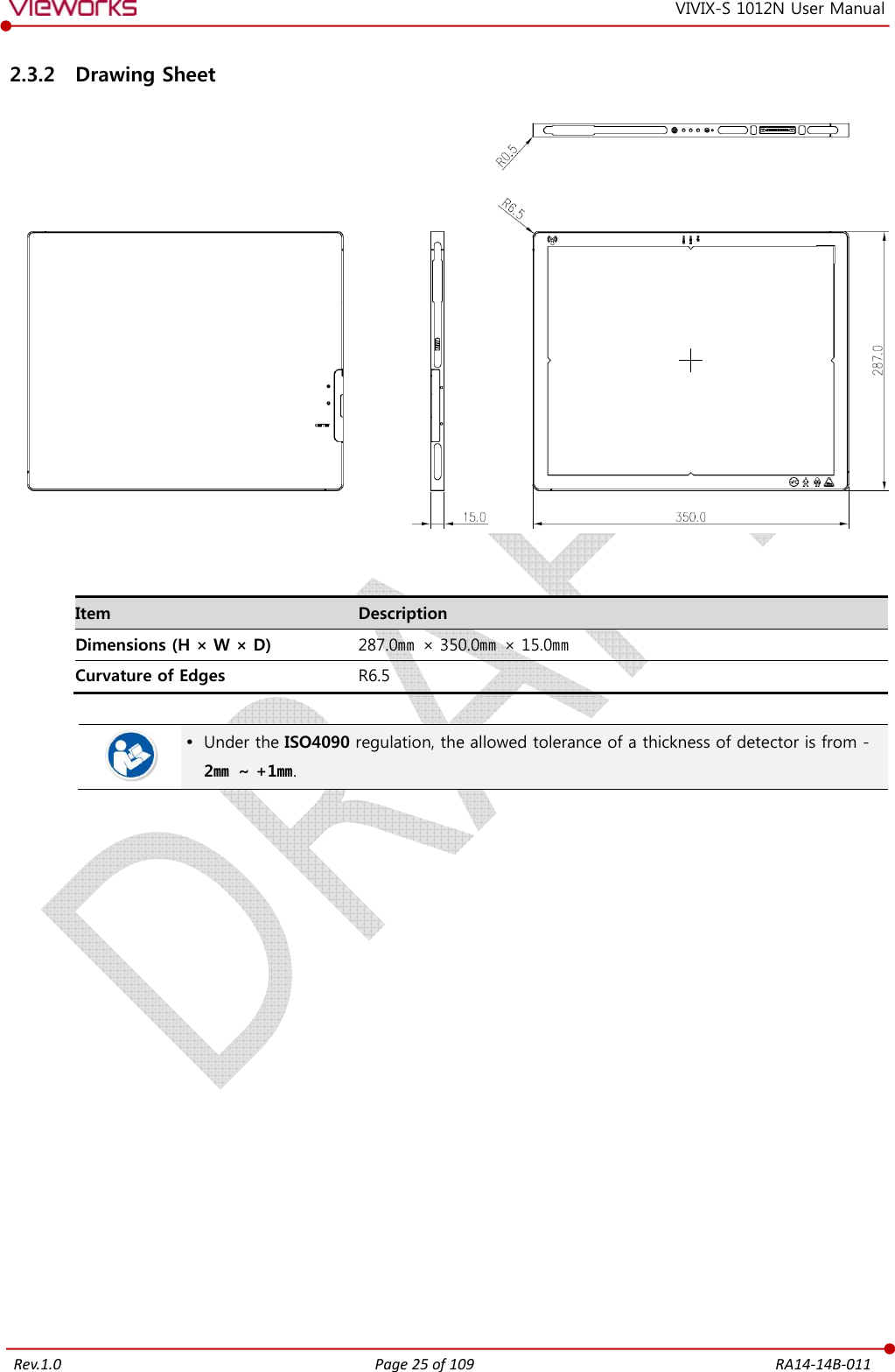
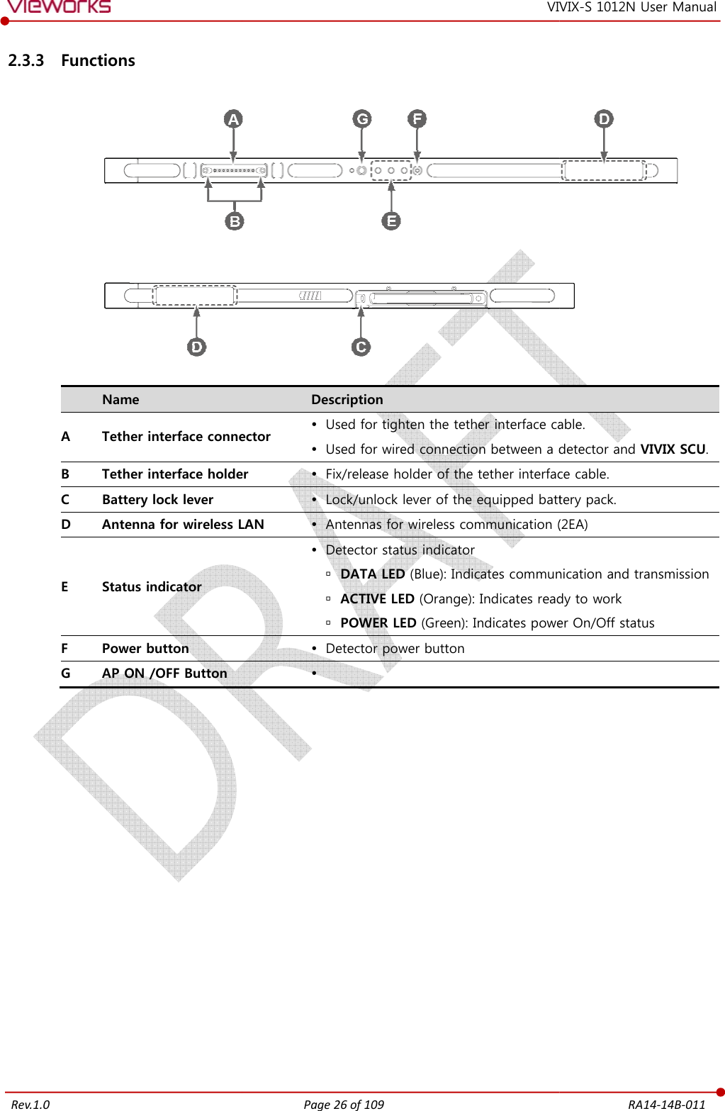
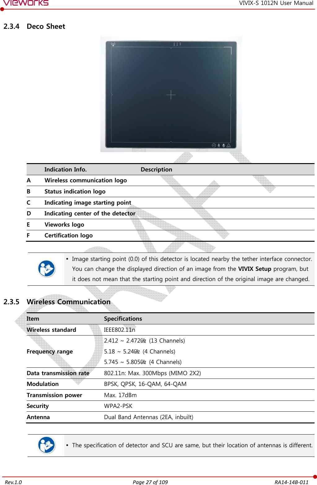
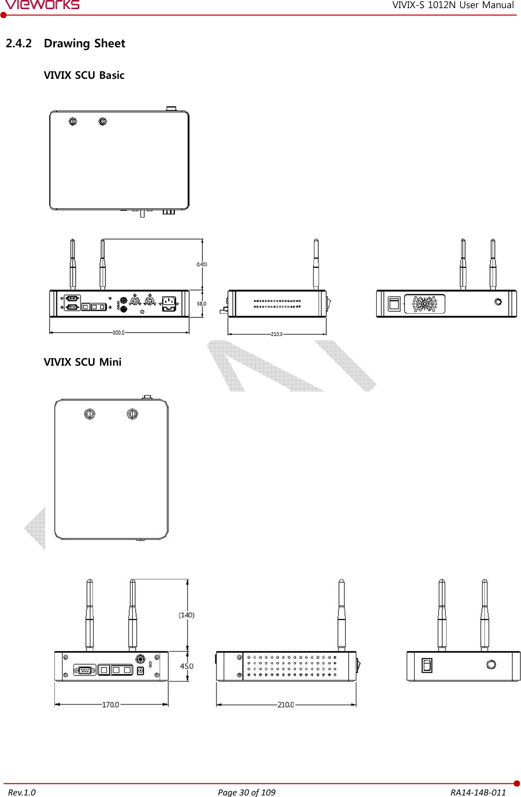
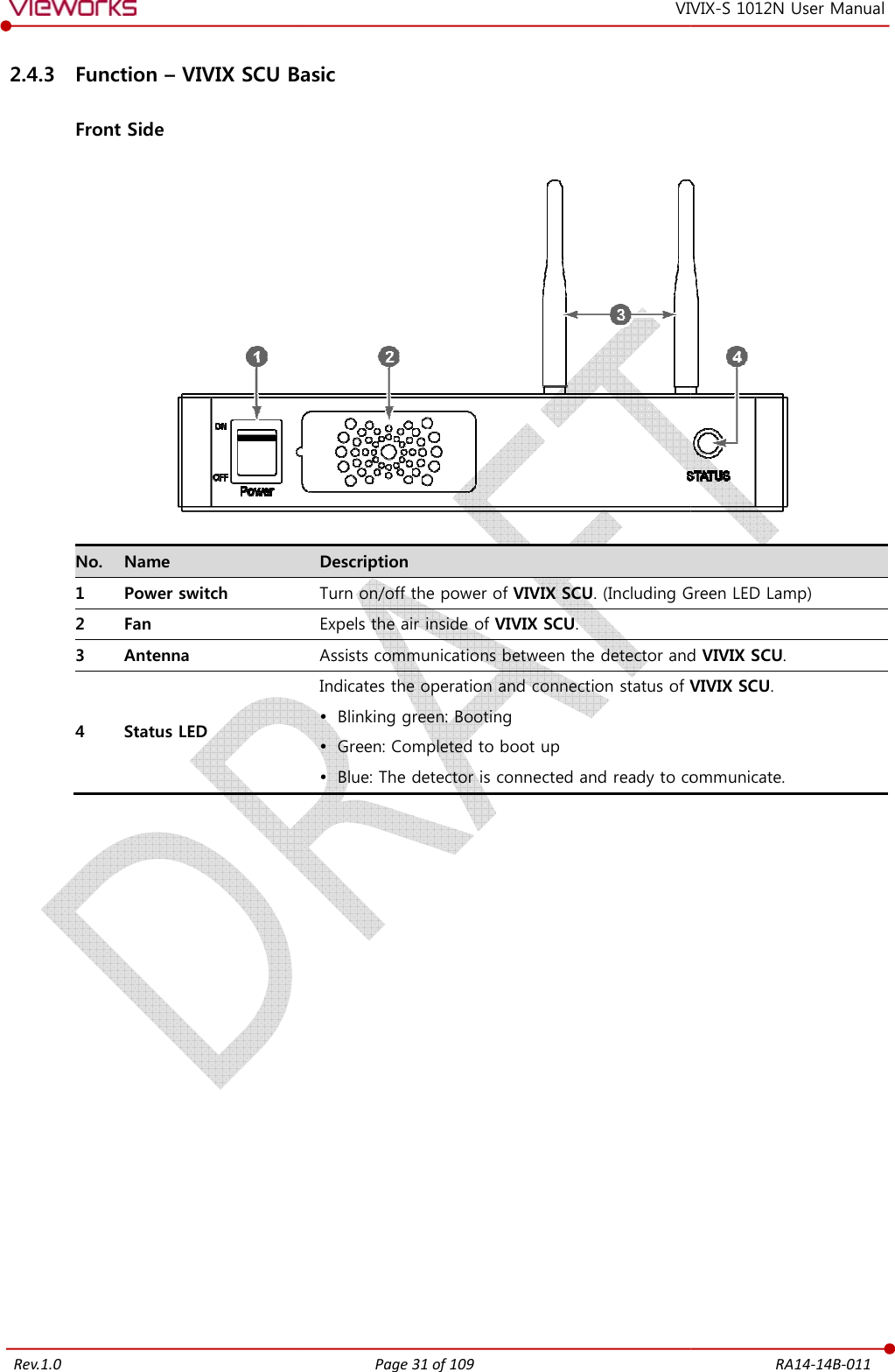
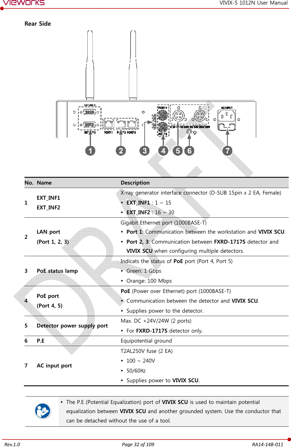
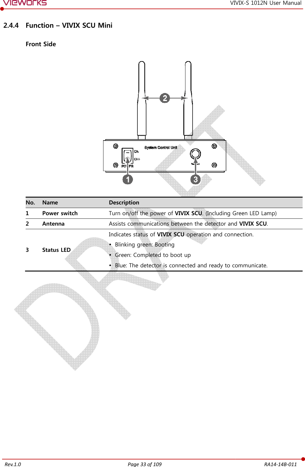
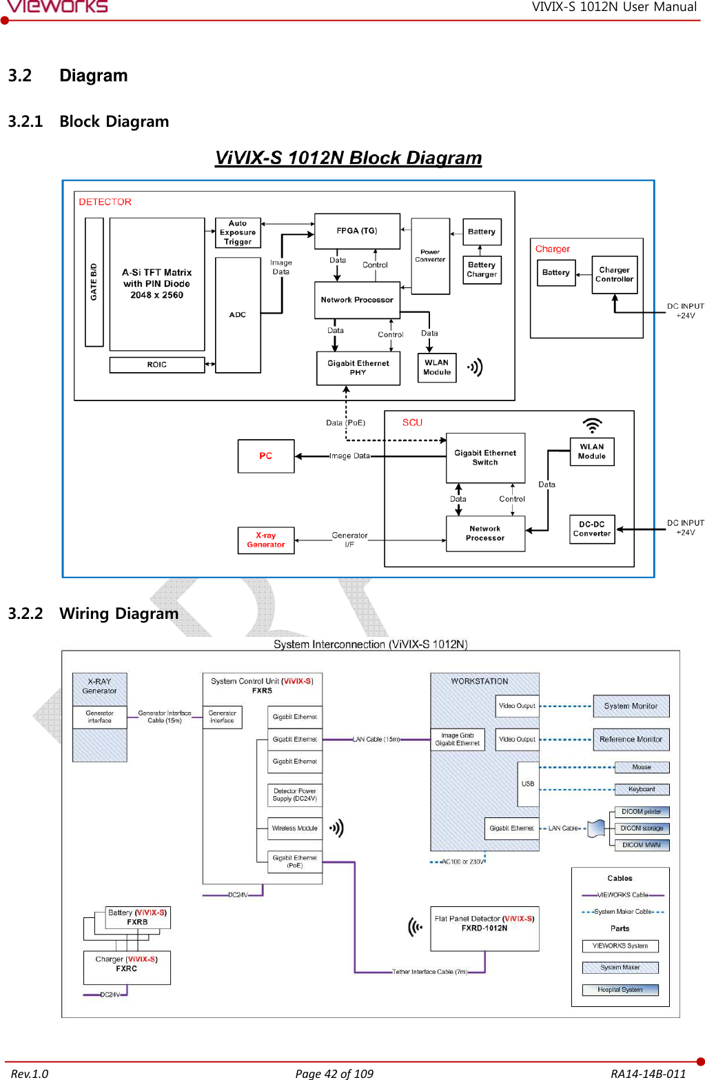
![Rev.1.0 Page 3 of 109 RA14-14B-011 VIVIX-S 1012N User Manual 2.2 Product Components ............................................................................................................................ 21 2.2.1 Detector............................................................................................................................................................................21 2.2.2 VIVIX SCU (VIVIX System Control Unit) .............................................................................................................21 2.2.3 Battery & Charger .......................................................................................................................................................22 2.2.4 Data ....................................................................................................................................................................................22 2.2.5 Other Accessories ........................................................................................................................................................22 2.3 VIVIX-S 1012N Detector ...................................................................................................................... 24 2.3.1 Specifications .................................................................................................................................................................24 2.3.2 Drawing Sheet ...............................................................................................................................................................25 2.3.3 Functions .........................................................................................................................................................................26 2.3.4 Deco Sheet [TBD] ......................................................................................................................................27 2.3.5 Wireless Communication..........................................................................................................................................27 2.3.6 Use Environment ..........................................................................................................................................................28 2.4 VIVIX SCU (VIVIX System Control Unit) ............................................................................................ 29 2.4.1 Specifications .................................................................................................................................................................29 2.4.2 Drawing Sheet ...............................................................................................................................................................30 2.4.3 Function – VIVIX SCU Basic ....................................................................................................................................31 2.4.4 Function – VIVIX SCU Mini .....................................................................................................................................33 2.5 Battery Pack ........................................................................................................................................... 35 2.5.1 Specifications .................................................................................................................................................................35 2.5.2 Drawing Sheet ...............................................................................................................................................................35 2.6 Battery Charger ..................................................................................................................................... 36 2.6.1 Specifications .................................................................................................................................................................36 2.6.2 Drawing Sheet ...............................................................................................................................................................36 2.7 Others [TBD] .......................................................................................................................... 37 2.7.1 X-ray Generator (Recommended Exposure Condition)..............................................................................37 2.7.2 Recommended Specification of Workstation (PC) .......................................................................................37 2.7.3 Recommended Specification of Grid ..................................................................................................................37 3. System Configuration ................................................................................................................... 39 3.1 Detector Connection Methods ........................................................................................................... 40 3.1.1 Wireless Connection ...................................................................................................................................................40 3.1.2 Wired Connection ........................................................................................................................................................41 3.2 Diagram ................................................................................................................................................... 42 3.2.1 Block Diagram ...............................................................................................................................................................42 3.2.2 Wiring Diagram ............................................................................................................................................................42](https://usermanual.wiki/Vieworks/FXRD-1012NAW.User-Manual-1/User-Guide-2532485-Page-4.png)
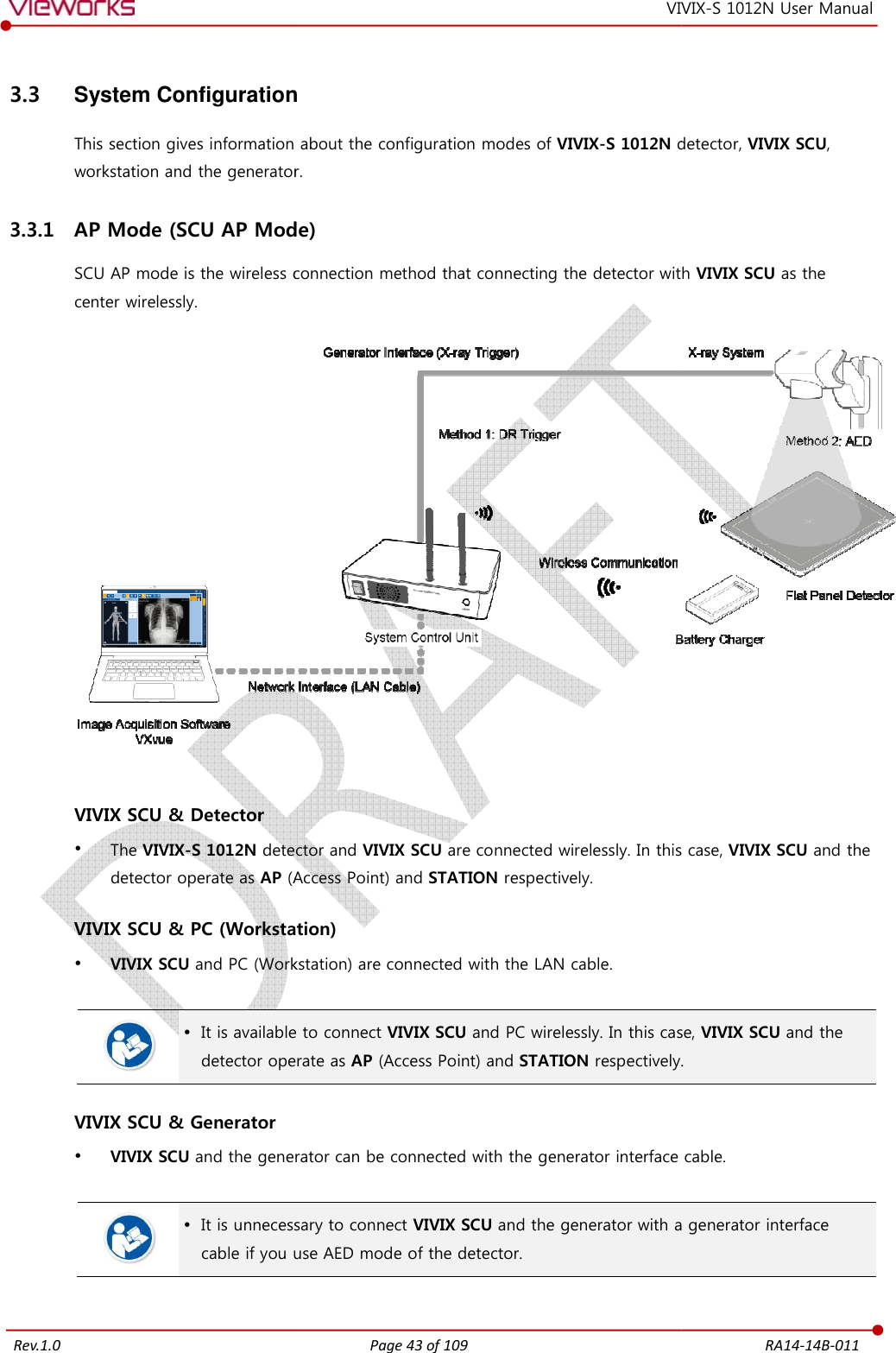
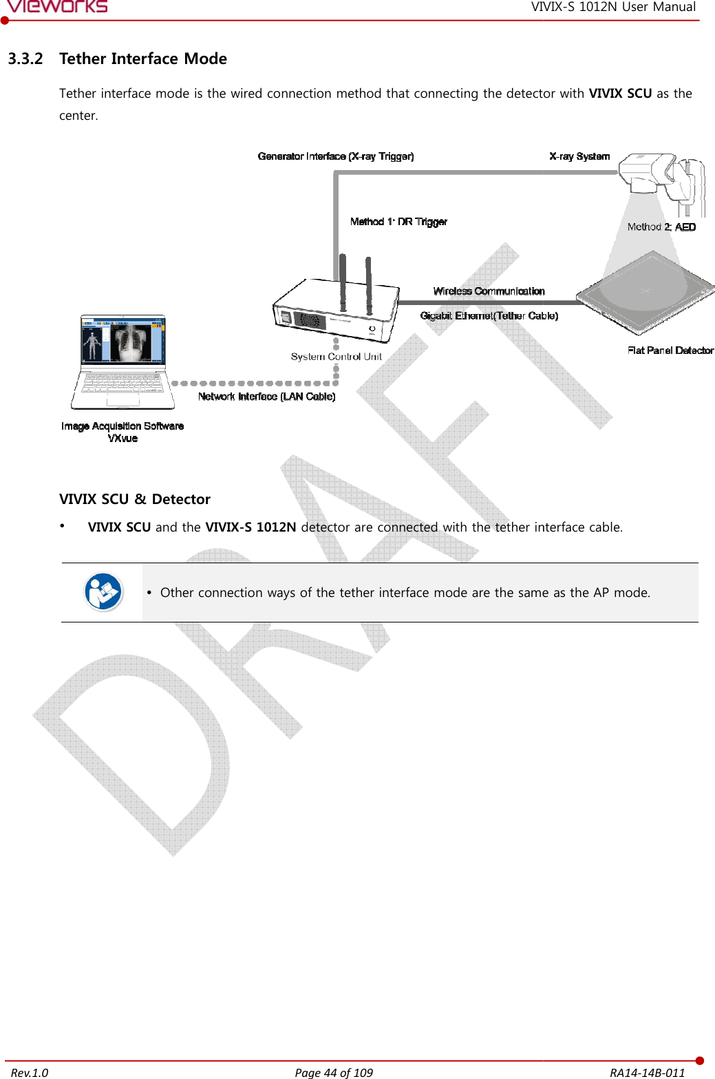
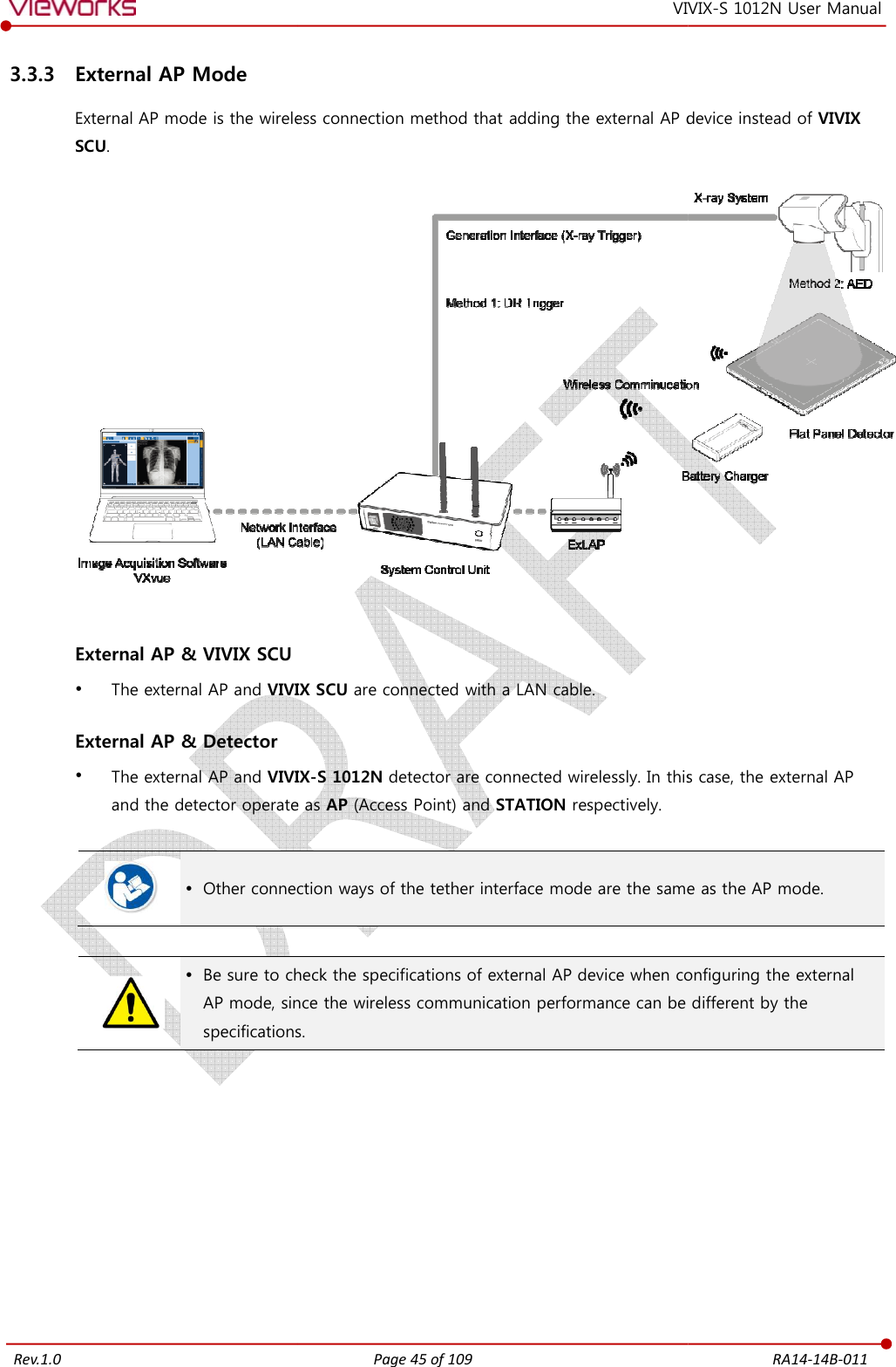
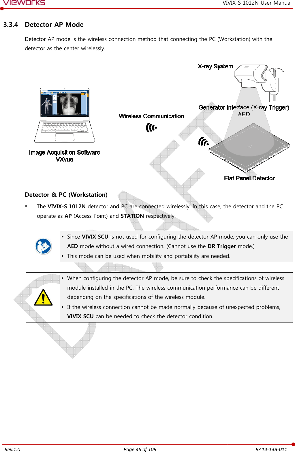
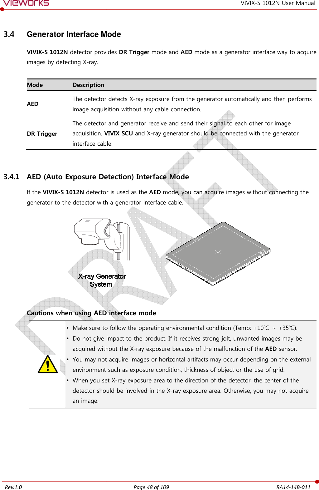
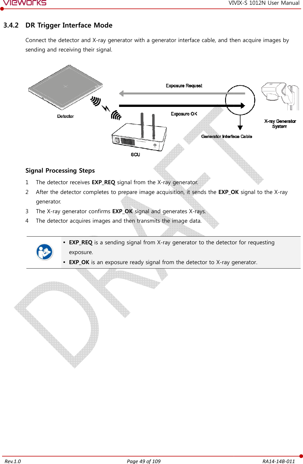
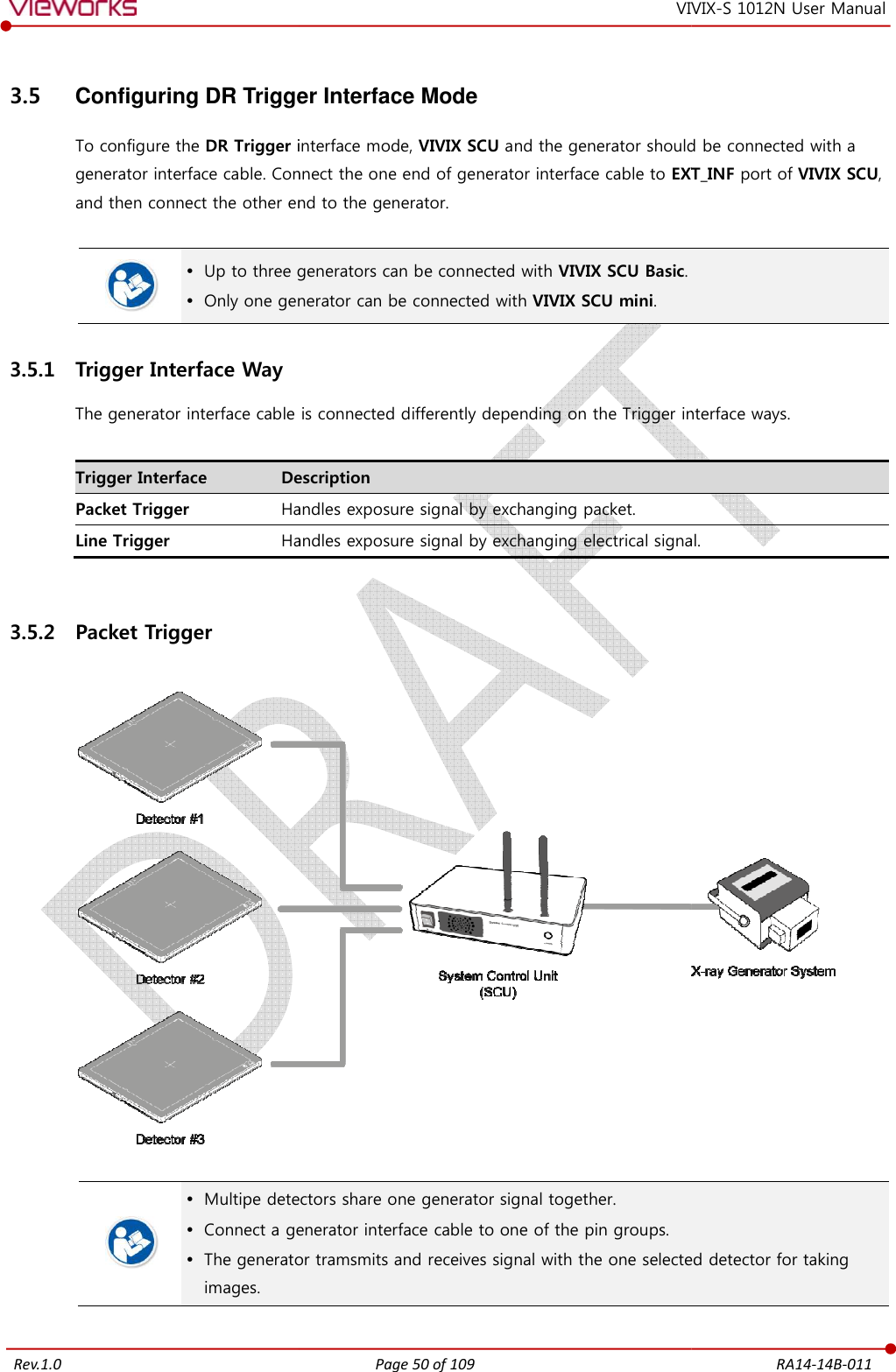
![Rev.1.0 Page 4 of 109 RA14-14B-011 VIVIX-S 1012N User Manual 3.3 System Configuration ........................................................................................................................... 43 3.3.1 AP Mode (SCU AP Mode)........................................................................................................................................43 3.3.2 Tether Interface Mode ...............................................................................................................................................44 3.3.3 External AP Mode ........................................................................................................................................................45 3.3.4 Detector AP Mode ......................................................................................................................................................46 3.3.5 Detector Stand-Alone Mode ..................................................................................................................................47 3.4 Generator Interface Mode ................................................................................................................... 48 3.4.1 AED (Auto Exposure Detection) Interface Mode ..........................................................................................48 3.4.2 DR Trigger Interface Mode .....................................................................................................................................49 3.5 Configuring DR Trigger Interface Mode ........................................................................................... 50 3.5.1 Trigger Interface Way .................................................................................................................................................50 3.5.2 Packet Trigger ................................................................................................................................................................50 3.5.3 Line Trigger .....................................................................................................................................................................51 3.5.4 EXT_INF Port Pin Map ...............................................................................................................................................52 3.5.5 Input / Output Circuit ................................................................................................................................................54 4. Installation [TBD] .............................................................................................................. 55 4.1 Battery Pack [TBD] ................................................................................................................... 56 4.1.1 How to insert a battery pack .................................................................................................................................56 4.1.2 How to datach a battery pack...............................................................................................................................57 4.1.3 How to charge a battery pack [TBD] ..................................................................................................58 4.2 Product Installation .............................................................................................................................. 60 4.2.1 Connecting Devices [TBD] .......................................................................................................................60 4.2.2 Booting up SCU [TBD] ...............................................................................................................................62 4.2.3 Booting up the Detector ..........................................................................................................................................62 4.2.4 Checking Status LED of Detector [TBD] ............................................................................................63 4.3 Software Installation ............................................................................................................................. 64 4.3.1 Software Classification [TBD] ..................................................................................................................64 4.3.2 Software Installation ...................................................................................................................................................64 4.4 Windows Environment Setting ........................................................................................................... 65](https://usermanual.wiki/Vieworks/FXRD-1012NAW.User-Manual-1/User-Guide-2532485-Page-5.png)
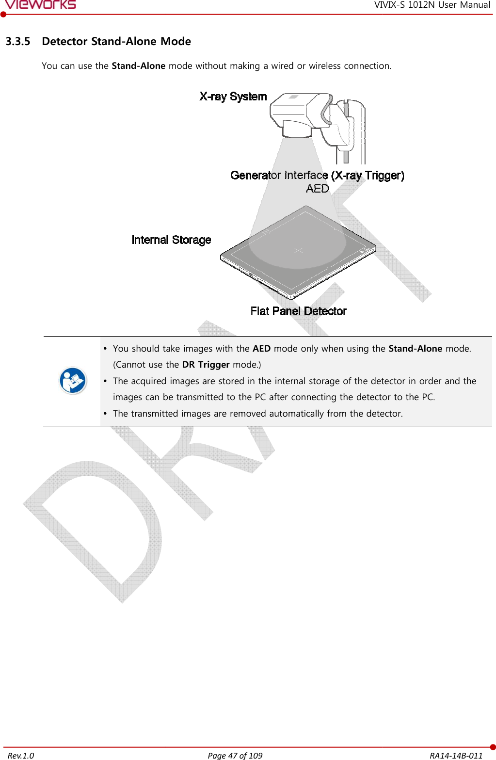
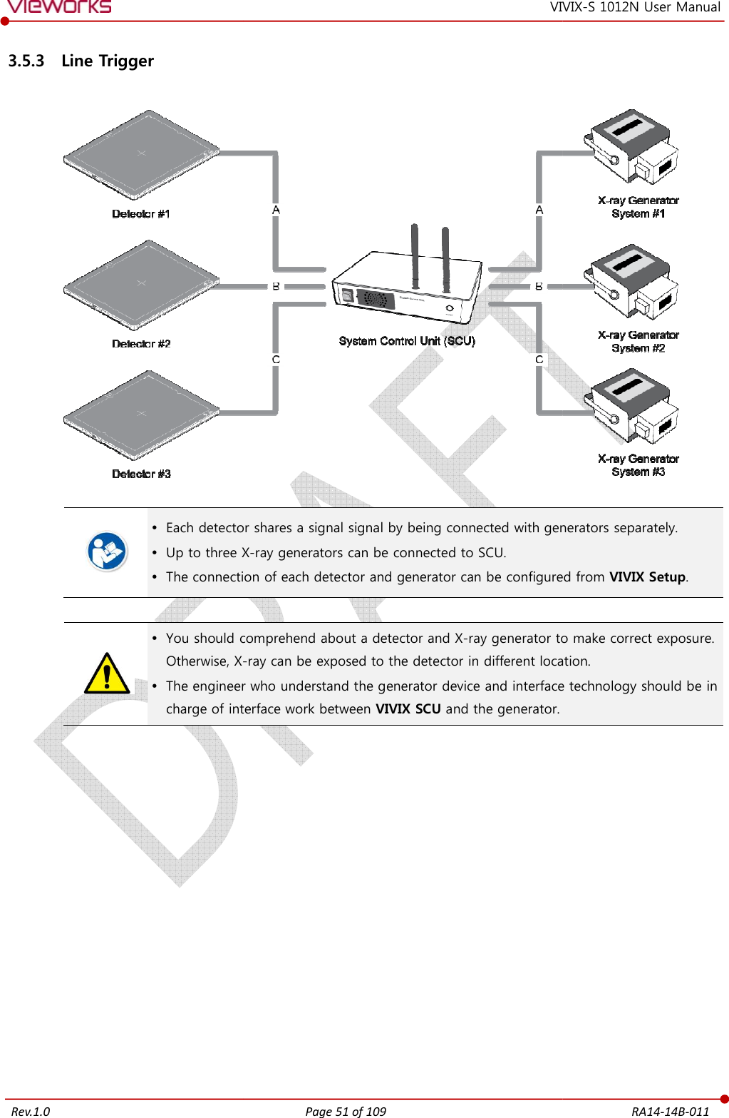
![Rev.1.0 Page 5 of 109 RA14-14B-011 VIVIX-S 1012N User Manual 4.4.1 Network Configuration [TBD] .................................................................................................................65 4.4.2 Disabling Sleep Mode of Monitor .......................................................................................................................69 5. Setting [TBD] ..................................................................................................................... 70 6. Calibration [TBD] .............................................................................................................. 74 7. Diagnosis, Inspection and Maintenance [TBD] ............................................................ 80 8. Troubleshooting [TBD] .................................................................................................... 89 9. Regulatory Information ................................................................................................................ 94 9.1 Medical Equipment Safety Standards ............................................................................................... 95 9.1.1 Medical Equipment Classification ........................................................................................................................95 9.1.2 Product Safety Standard ...........................................................................................................................................95 9.2 Radio Frequency Compliance Information ....................................................................................... 97 9.2.1 FCC Compliance ...........................................................................................................................................................97 9.3 Labels and Symbols .............................................................................................................................. 98 9.3.1 Label ..................................................................................................................................................................................98 9.3.2 Product Serial Number........................................................................................................................................... 100 9.3.3 Product Symbols ....................................................................................................................................................... 101 9.4 Guidance and Manufacturer’s Declaration for EMC ..................................................................... 102 9.4.1 Electromagnetic Emissions ................................................................................................................................... 102 9.4.2 Electromagnetic Immunity .................................................................................................................................... 103 10. Information ................................................................................................................................ 106 10.1 Service Information ........................................................................................................................ 107 10.1.1 Product Lifetime ........................................................................................................................................................ 107 10.1.2 Regular Inspection and Maintenance ............................................................................................................. 107 10.1.3 Repair ............................................................................................................................................................................. 107 10.1.4 Replacement Parts Support ................................................................................................................................. 107 10.1.5 Consumables ............................................................................................................................................................... 107 10.2 Warranty ............................................................................................................................................ 108 10.3 Revision History ............................................................................................................................... 109](https://usermanual.wiki/Vieworks/FXRD-1012NAW.User-Manual-1/User-Guide-2532485-Page-6.png)

![Rev.1.0 Page 20 of 109 RA14-14B-011 VIVIX-S 1012N User Manual 2.1 Overview ViVIX-S 1012N detector is the digital X-ray imaging solution. It acquires images by exposing X-ray which has been penetrated the human body. When X-ray photons pass through scintillator in the detector, the photons convert to visible ray, and the visible ray is converted to electronic signals through TFT (a-Si). Then the detector digitalizes x-ray images and transfers them to the computer (workstation) for radiography diagnostics. Users can perform image diagnosis easily through the image display monitor with this process. Advanced digital image processing also allows considerably efficient diagnosis, all kinds of information management, and sharing of image information on network. This detector is used for the general-purpose diagnostic procedures, and it is intended to replace radiographic film / screen systems. This detector is not intended for mammography applications. 2.1.1 Features [TBD] Since VIVIX-S 1012N detector is compatible with a conventional film cassette, it enables to replace the analog radiographic diagnosis (Supporting ISO4090 standard). The new sensor with 124μm pixel pitch produces high spatial resolution (approx. 5.2 Mega pixels) digital images. Various applications such as neonatal, ENT, equine and cephalo Choose between two scintillator types (CsI and Gadox) of detector provided by Vieworks. The built-in wireless communication supports IEEE 802.11n to acquire images without a wired connection in anytime, anywhere. Make direct wireless communication with the built-in wireless AP function. (Inside APTM) Supports the stable and reliable AED (Auto Exposure Detection) function. (AnytimeTM) Designed as lightweight and thin with portability to allow easy exposure in anytime, anywhere. Used in various ways for infant / animals and in the dental clinic / ENT, etc.](https://usermanual.wiki/Vieworks/FXRD-1012NAW.User-Manual-1/User-Guide-2532485-Page-21.png)
![Rev.1.0 Page 21 of 109 RA14-14B-011 VIVIX-S 1012N User Manual 2.2 Product Components 2.2.1 Detector Component Description VIVIX-S 1012N Detector FXRD-1012NAW (2.2kg) FXRD-1012NBW (2.1kg) Calibration DATA (CD) [TBD] Offset Calibration Data Gain Calibration Data Defect Map Data A deco sheet attached on the detector can be different depending on each client company. 2.2.2 VIVIX SCU (VIVIX System Control Unit) Component Description VIVIX SCU Basic FXRS-03A (2.5kg) FXRS-03B (2.8kg) AC Power Cable (2m) VIVIX SCU mini FXRS-04A (1.2kg) You can choose either VIVIX SCU Basic or VIVIX SCU mini depending on the purpose of use.](https://usermanual.wiki/Vieworks/FXRD-1012NAW.User-Manual-1/User-Guide-2532485-Page-22.png)
![Rev.1.0 Page 22 of 109 RA14-14B-011 VIVIX-S 1012N User Manual 2.2.3 Battery & Charger Component Description VIVIX Battery [TBD] FXRB-03A (0.12kg, 2EA) VIVIX Charger [TBD] FXRC-02A (0.8kg) DC 24V 2.2.4 Data Component Description Calibration Data Pre-offset data Post-offset data Gain data Defect map data Resource Software (Viewer or SDK) Manuals 2.2.5 Other Accessories Component Description Cables Tether Interface Cable (7m) Ether Con Cable (7m, Option) Generator Interface Cable (7m) UTP LAN Cable (15m, Direct) CAT 5E or CAT6](https://usermanual.wiki/Vieworks/FXRD-1012NAW.User-Manual-1/User-Guide-2532485-Page-23.png)
![Rev.1.0 Page 28 of 109 RA14-14B-011 VIVIX-S 1012N User Manual 2.3.6 Use Environment Item Operation Storage & Transportation Temperature +10 ~ +35℃ -15 ~ +55℃ Humidity 30 ~ 85% (Non-condensing) 10 ~ 90% (Non-condensing) Atmospheric pressure 700 ~ 1060 hPa 500 ~ 1060 hPa Shock 1.6G 20G Vibration 0.7G 0.7G The use environment of detector and VIVIX SCU is same. Load Limit of Detector [TBD] Uniform load Local load Over the whole surface Center diameter 40mm Max. ?? kg Max. ?? kg Do not let the paitent or object heavier than load limit be on the detector. Then, detector can be damaged. Do not let the patient lie or get on the detector. Internal devices such as a sensor can be seriously damaged even if his/her weight is within the load limit.](https://usermanual.wiki/Vieworks/FXRD-1012NAW.User-Manual-1/User-Guide-2532485-Page-29.png)
![Rev.1.0 Page 37 of 109 RA14-14B-011 VIVIX-S 1012N User Manual 2.7 Others [TBD] 2.7.1 X-ray Generator (Recommended Exposure Condition) Item Recommended condition X-ray energy range 40kVp ~ 150kVp Reliability (Lifetime Dose) 74Gy or higher (35 uGy x 365days x 24hrs x 60min. x 60sec. / 15sec.) 2.7.2 Recommended Specification of Workstation (PC) Item Recommended specification Operating System VIVIX Setup Microsoft Windows 7 (32bit / 64bit) Microsoft Windows 7 64bit SP1 (Professional Edition or higher) Microsoft Windows Vista Service pack 1 or higher (32bit / 64bit) Microsoft Windows 8 (32bit / 64bit) / 8.1 64bit SP1 (Professional Edition or higher Microsoft Windows 8.2 (32bit / 64bit) CPU Intel Core i5 2600 or higher (or compatible CPU) Memory 4GB or higher Hard Disk 1TB or higher LAN Card (only for detector communication) Gigabit (for detector only) Intel® PRO 1000 Series (Gigabit LAN Card for network interface) Min.requiremetns Speed: 1Gbps or more Jumbo Frames: 9K Receive Descriptors: 2K (1024 or higher) Monitor 1024 x 768 or more CD-ROM CD or DVD R/W 2.7.3 Recommended Specification of Grid Item Recommended specification SID 100cm / 130cm / 150cm / 180cm Size 451mm x 365mm x 1.5mm Ratio 8.1 / 10:1 / 12:1 Frequency 215 line/inch INTER SPACER AL](https://usermanual.wiki/Vieworks/FXRD-1012NAW.User-Manual-1/User-Guide-2532485-Page-38.png)

![Rev.1.0 Page 55 of 109 RA14-14B-011 VIVIX-S 1012N User Manual 4. Installation [TBD] This section gives information about the installation process and method to use a detector. Battery Pack Product Installation Generator Connection Software Installation Windows Environment Setting](https://usermanual.wiki/Vieworks/FXRD-1012NAW.User-Manual-1/User-Guide-2532485-Page-56.png)
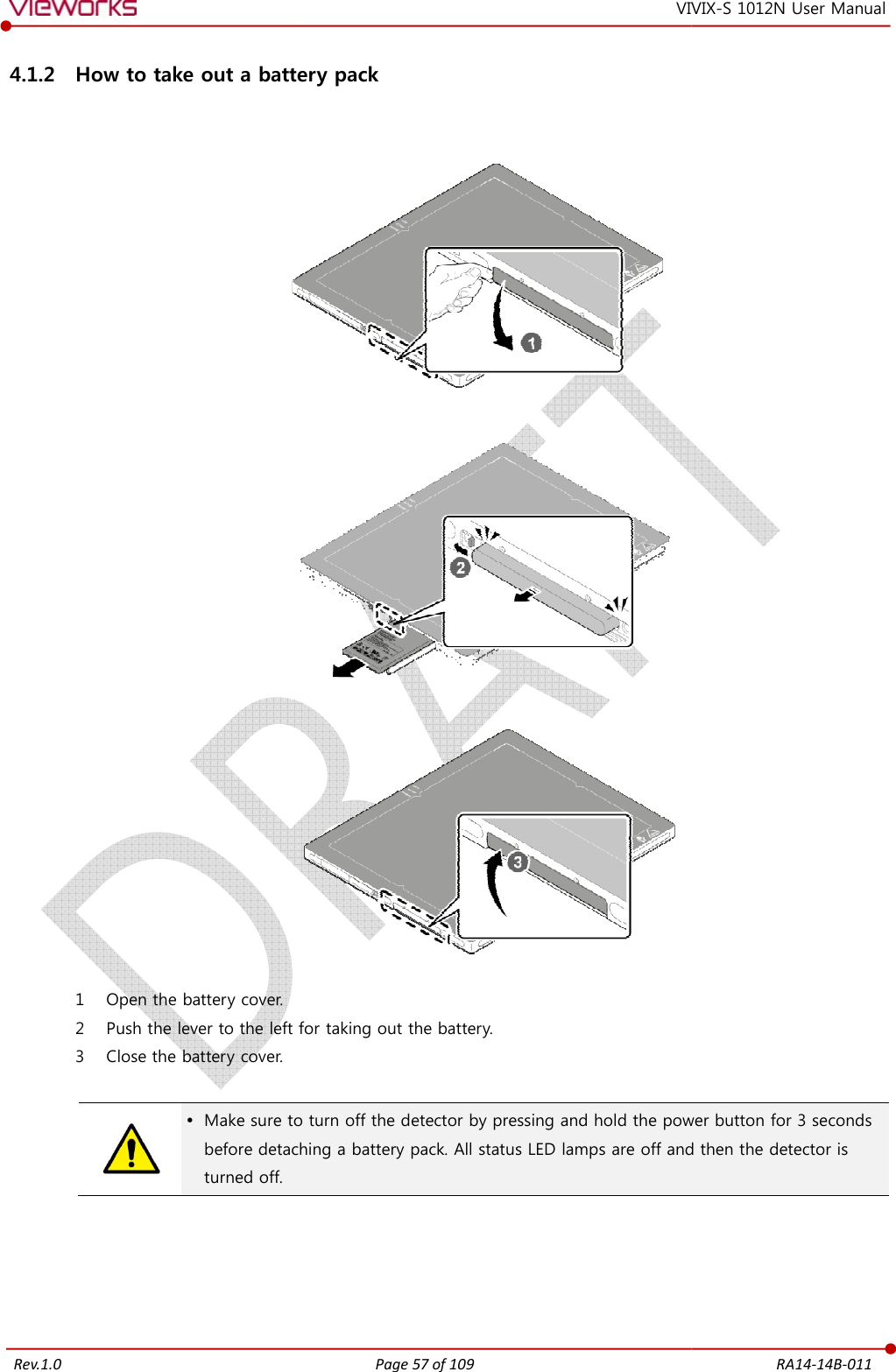
![Rev.1.0 4.1 Battery Pack[TBD] Detector and its attached devices should be If you encounter any problems, consult engineer. 4.1.1 How to insert a battery pack 1 Open the battery cover. 2 Insert a battery into a slot until it clicks and push the 3 Close the battery cover. Check if the Make sure that the battery pack is securely The remaining battery can be checked fromfrom the VIVIXPage 56 of 109 VIVIX[TBD] and its attached devices should be installed by an authorized If you encounter any problems, consult the sales representative in Vieworks How to insert a battery pack battery into a slot until it clicks and push the lever to the right for fixing the battery Check if the battery is fully charged before using. Make sure that the battery pack is securely inserted. The remaining battery can be checked from the battery lamp on the side of detector VIVIX Setup program. RA14-14B-011 VIX-S 1012N User Manual n authorized service engineer. in Vieworks or a relevant fixing the battery. lamp on the side of detector or](https://usermanual.wiki/Vieworks/FXRD-1012NAW.User-Manual-1/User-Guide-2532485-Page-57.png)