Vieworks FXRD-1012NAW Flat Panel Detector User Manual ViVIX S 1417W x
Vieworks Co., Ltd. Flat Panel Detector ViVIX S 1417W x
UserManual.wiki
>
Vieworks
>
FXRD-1012NAW User Manual
>
REVISED Users Manual
Contents
1.
User Manual 1
2.
User Manual 2
3.
REVISED Users Manual
REVISED Users Manual
Navigation menu
Upload a User Manual
Namespaces
Wiki Guide
HTML
PDF
Info
Views
User Manual
Discussion / Help
Navigation
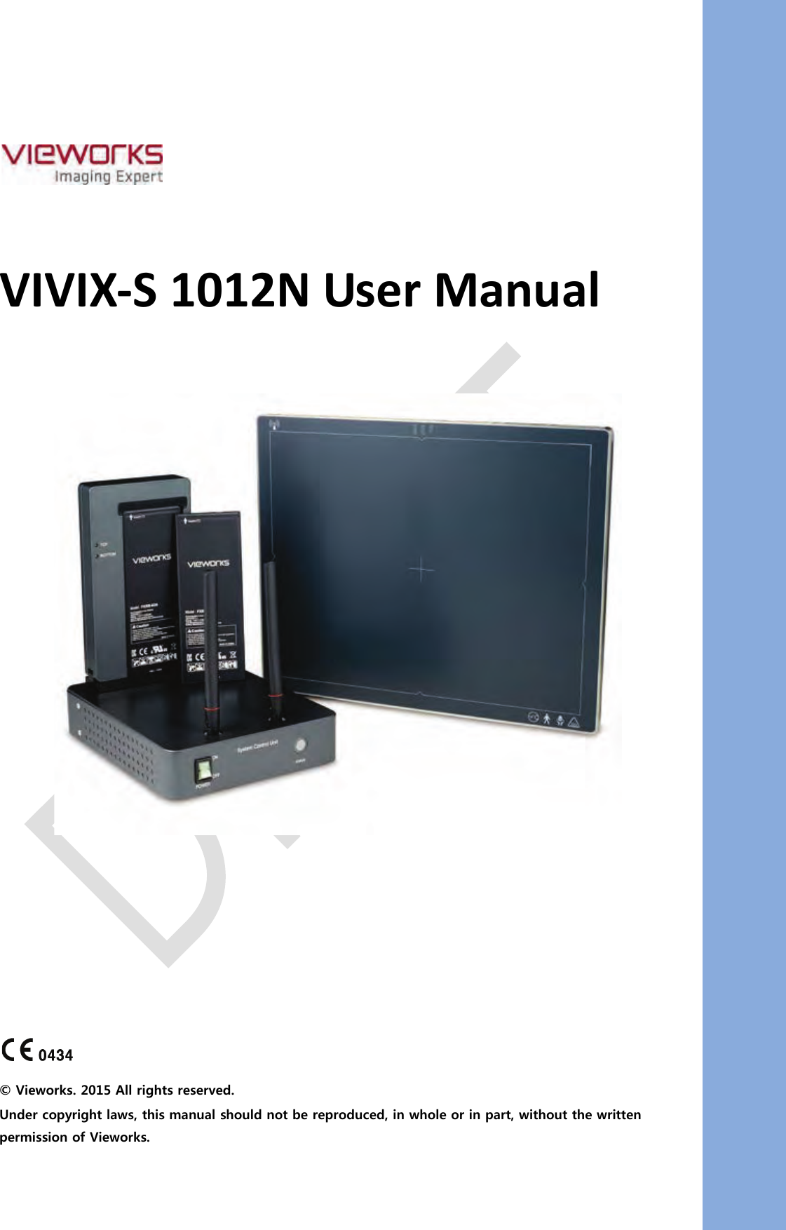

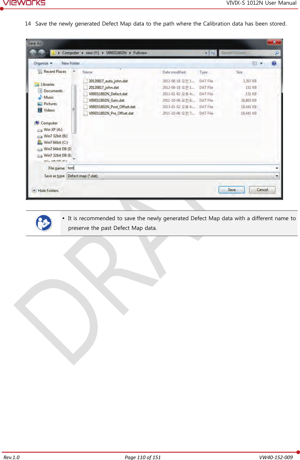
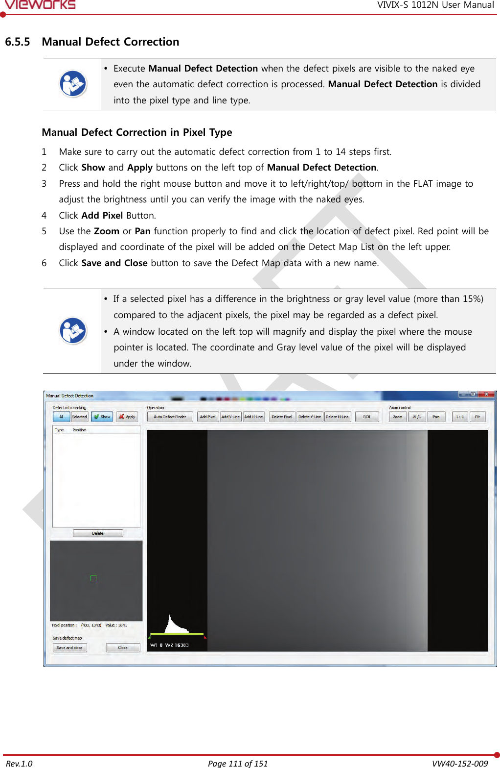
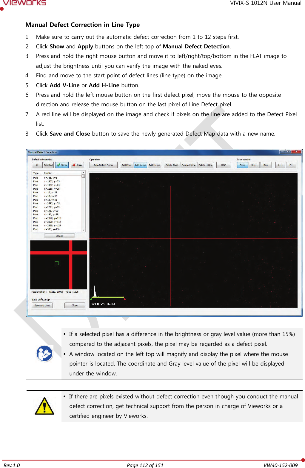
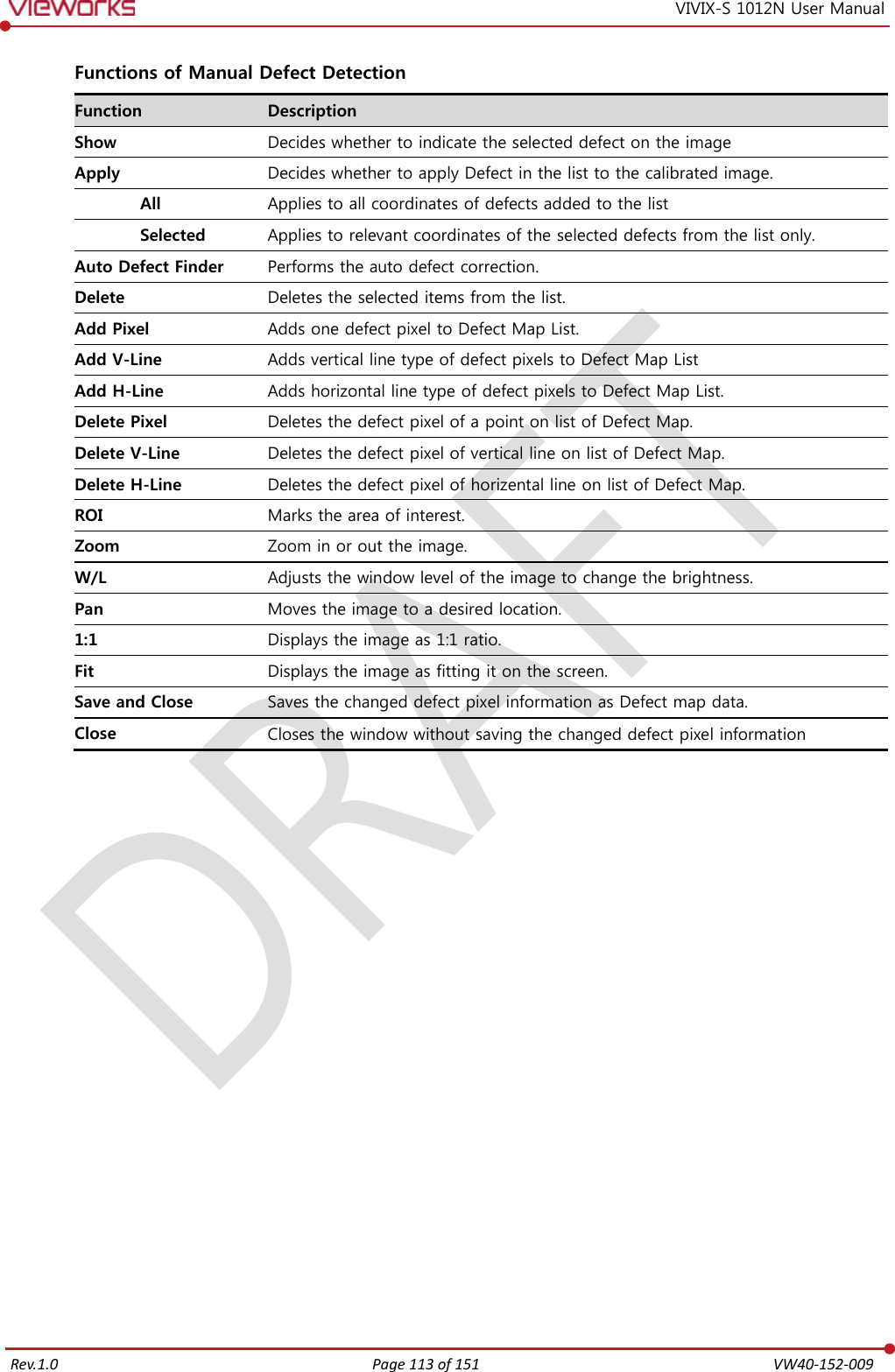
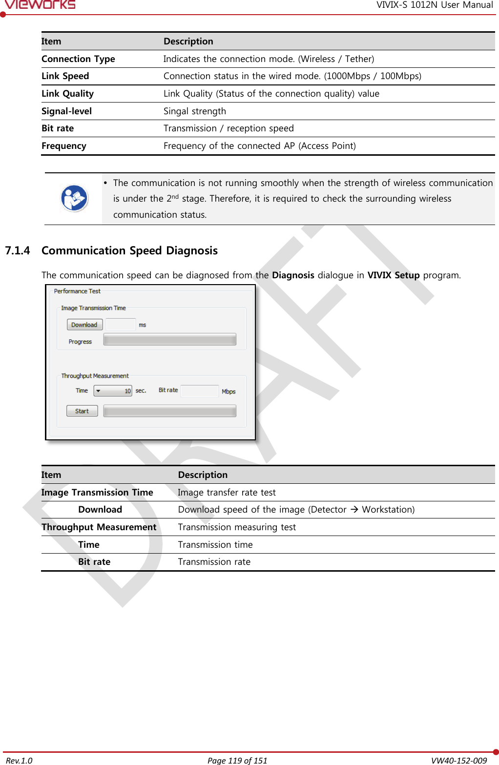
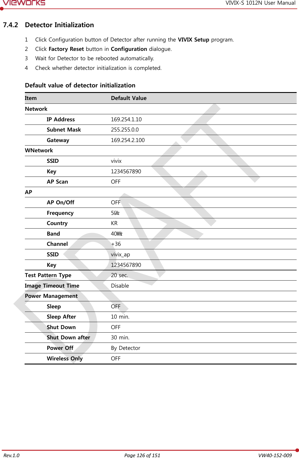
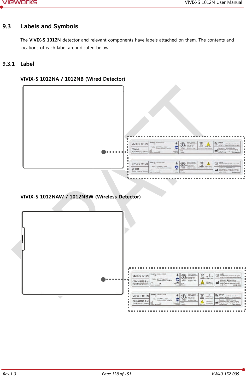
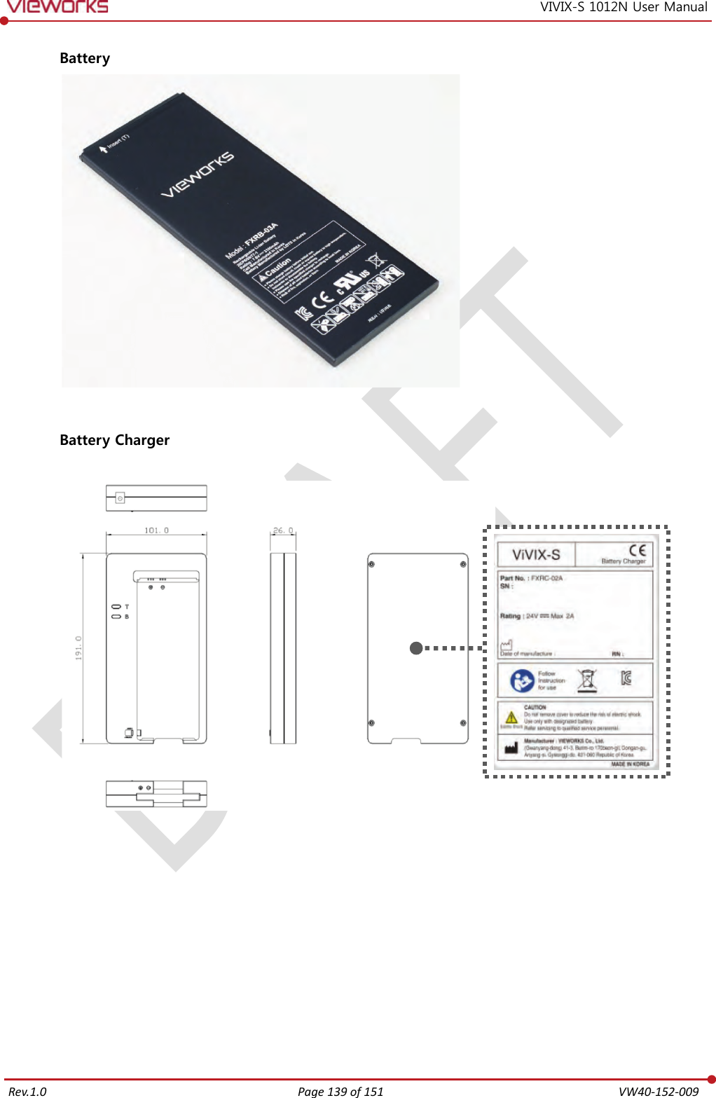
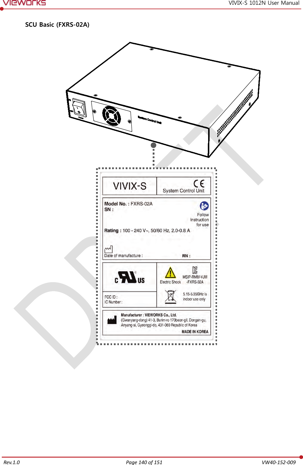
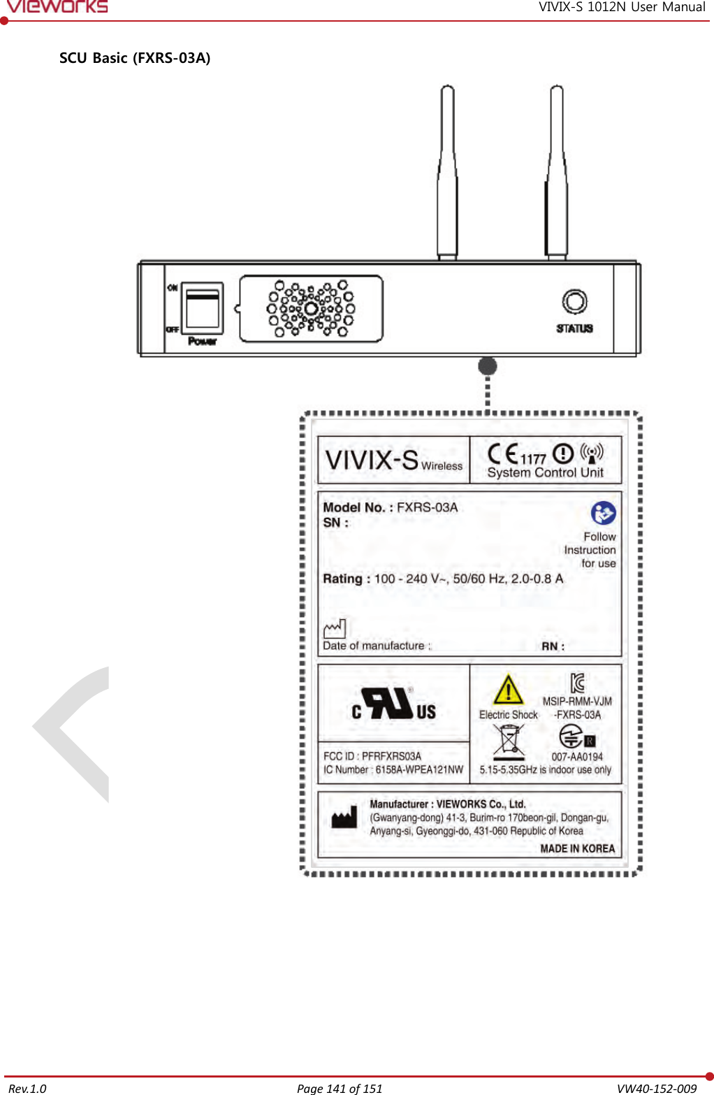
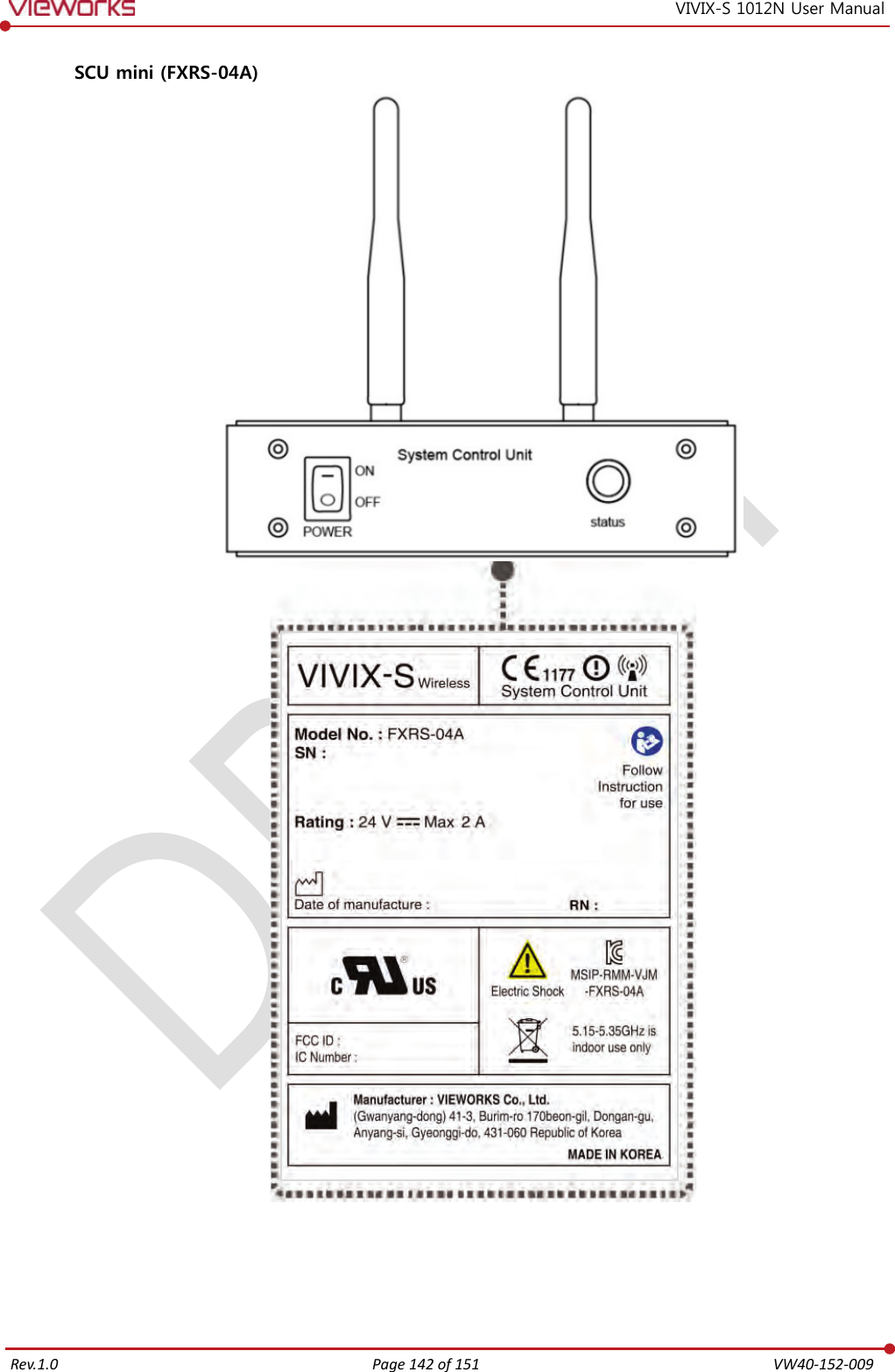
![Rev.1.0 Page 143 of 151 VW40-152-009 VIVIX-S 1012N User Manual Outer Box [TBD] 9.3.2 Product Serial Number Serial Number Composition The serial numbers for each product or accessory are composed as follows. V 1 D A B J 0 0 1 Item Composition Year Month Serial number Revision will be updated in case of follows. Mass production or a large amount of order. Exterior alteration. Item code will be produced based on internal management standard of vieworks. Composition code is like follows. D: Detector S: SCU C: Battery Charger Range of Serial Number is 001 ~ 999. Initial Per Year 11 12 13 14 15 16 17 18 19 20 AA AB AC AD AE AF AG AH AI BJ Initial Per Month 1 2 3 4 5 6 7 8 9 10 11 12 A B C D E F U V W X Y Z Composition of Serial Number for Each Item Model Composition Serial Number 1012NA Detector VCDAEA001 1012NB Detector VDDAEA001 1012NAW Detector VADAEA001 1012NBW Detector VBDAEA001 FXRC-02A Battery Charger VACAEA001 FXRS-03A SCU Basic VCSAEA001 FXRS-04A SCU mini VASAEA001](https://usermanual.wiki/Vieworks/FXRD-1012NAW.REVISED-Users-Manual/User-Guide-2772908-Page-143.png)
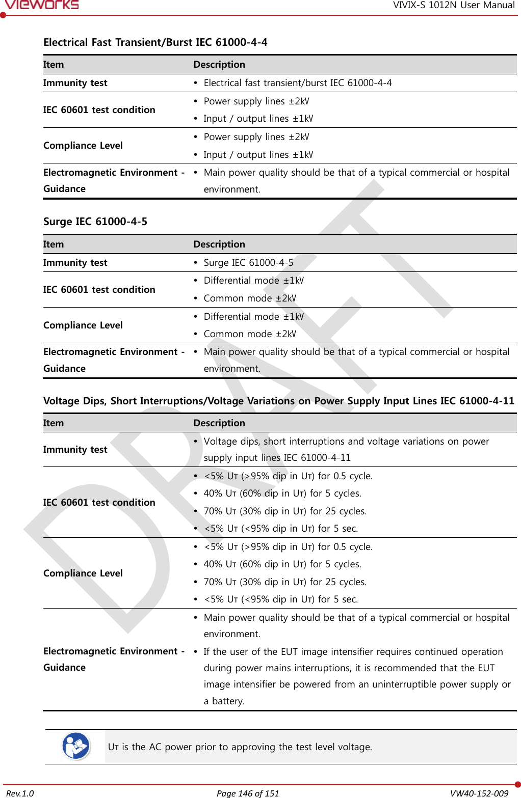
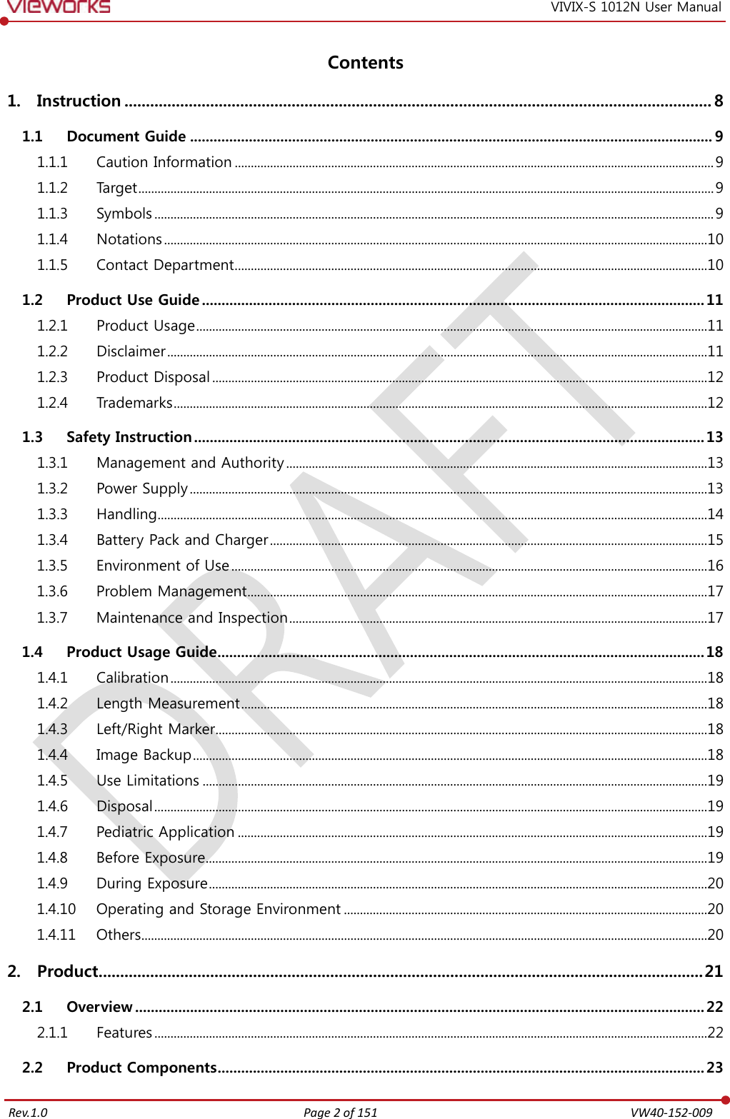
![Rev.1.0 Page 147 of 151 VW40-152-009 VIVIX-S 1012N User Manual Power Frequency (50/60 ㎐) Magnetic Field IEC 61000-4-8 Item Description Immunity test Power frequency (50/60 ㎐) magnetic field IEC 61000-4-8 IEC 60601 test condition 3 A/m Compliance Level 3 A/m Electromagnetic Environment - Guidance Power frequency magnetic fields should be at levels characteristic of a typical location in a typical commercial or hospital environment. Conducted RF IEC 61000-4-6 / Radiated RF IEC 61000-4-3 Item Description Immunity test Conducted RF IEC 61000-4-6 Radiated RF IEC 61000-4-3 IEC 60601 test condition 3 Vrms 150 ㎑ to 80 ㎒ 3 V/m 80 ㎒ to 2.5 ㎓ Compliance Level 3 Vrms 150 ㎑ to 80 ㎒ 3 V/m 80 ㎒ to 2.5 ㎓ Electromagnetic Environment - Guidance Portable and mobile RF communications equipment should be used no closer to any part of the EUT, including cables, than the recommended separation distance calculated from the below equations applicable to the frequency of the transmitter. P is the maximum output power rating of the transmitter in watts (W) according to the transmitter manufacturer and d is the recommended separation distance in meters (m). Field strengths from fixed RF transmitters, as determined by an electromagnetic site surveya, should be less than the compliance level in each frequency range b. Interference may occur in the vicinity of equipment marked with the symbol. At 80 ㎒ and 800 ㎒, the higher frequency range applies. These guidelines may not apply in all situations. Electromagnetic propagation is affected by absorption and reflection from structures, objects and people. Field strengths from fixed transmitters, such as base stations for radio (cellular/cordless) telephones and land mobile radios, amateur radio, AM and FM radio broadcast and TV broadcast cannot be predicted theoretically with accuracy. To assess the electromagnetic environment due to fixed RF transmitters, an electromagnetic site survey should be considered. If the measured field strength in the location in which EUT is used exceeds the applicable RF compliance level above, EUT should be observed to verify normal operation. If abnormal performance is observed, additional measures may be necessary, such as reorienting or relocating EUT. Over the frequency range 150 ㎑ to 80 ㎒, field strengths should be less than [V1] V/m.](https://usermanual.wiki/Vieworks/FXRD-1012NAW.REVISED-Users-Manual/User-Guide-2772908-Page-147.png)