Vieworks FXRD-1012NAW Flat Panel Detector User Manual ViVIX S 1417W x
Vieworks Co., Ltd. Flat Panel Detector ViVIX S 1417W x
Vieworks >
Contents
- 1. User Manual 1
- 2. User Manual 2
- 3. REVISED Users Manual
REVISED Users Manual

Rev.1.0
Page 2 of 151 VW40-152-009
VIVIX-S 1012N User Manual
Contents
1. Instruction ......................................................................................................................................... 8
1.1 Document Guide ..................................................................................................................................... 9
1.1.1 Caution Information ..................................................................................................................................................... 9
1.1.2 Ta rg e t ................................................................................................................................................................................... 9
1.1.3 Symbols .............................................................................................................................................................................. 9
1.1.4 Notations .........................................................................................................................................................................10
1.1.5 Contact Department ...................................................................................................................................................10
1.2 Product Use Guide ................................................................................................................................ 11
1.2.1 Product Usage ...............................................................................................................................................................11
1.2.2 Disclaimer ........................................................................................................................................................................11
1.2.3 Product Disposal ..........................................................................................................................................................12
1.2.4 Trademarks ......................................................................................................................................................................12
1.3 Safety Instruction .................................................................................................................................. 13
1.3.1 Management and Authority ...................................................................................................................................13
1.3.2 Power Supply .................................................................................................................................................................13
1.3.3 Handling ...........................................................................................................................................................................14
1.3.4 Battery Pack and Charger ........................................................................................................................................15
1.3.5 Environment of Use ....................................................................................................................................................16
1.3.6 Problem Management ...............................................................................................................................................17
1.3.7 Maintenance and Inspection ..................................................................................................................................17
1.4 Product Usage Guide ............................................................................................................................ 18
1.4.1 Calibration .......................................................................................................................................................................18
1.4.2 Length Measurement .................................................................................................................................................18
1.4.3 Left/Right Marker.........................................................................................................................................................18
1.4.4 Image Backup ................................................................................................................................................................18
1.4.5 Use Limitations .............................................................................................................................................................19
1.4.6 Disposal ............................................................................................................................................................................19
1.4.7 Pediatric Application ..................................................................................................................................................19
1.4.8 Before Exposure ............................................................................................................................................................19
1.4.9 During Exposure ...........................................................................................................................................................20
1.4.10 Operating and Storage Environment .................................................................................................................20
1.4.11 Others................................................................................................................................................................................20
2. Product ............................................................................................................................................. 21
2.1 Overview ................................................................................................................................................. 22
2.1.1 Features ............................................................................................................................................................................22
2.2 Product Components ............................................................................................................................ 23

Rev.1.0
Page 3 of 151 VW40-152-009
VIVIX-S 1012N User Manual
2.2.1 Detector............................................................................................................................................................................23
2.2.2 SCU (System Control Unit) ......................................................................................................................................23
2.2.3 Battery & Charger .......................................................................................................................................................24
2.2.4 Accessaries ......................................................................................................................................................................25
2.3 VIVIX-S 1012N Detector ...................................................................................................................... 26
2.3.1 Specifications .................................................................................................................................................................26
2.3.2 Drawing Sheet ...............................................................................................................................................................27
2.3.3 Functions .........................................................................................................................................................................29
2.3.4 Deco Sheet .....................................................................................................................................................................31
2.3.5 Wireless Communication..........................................................................................................................................33
2.3.6 Use Environment ..........................................................................................................................................................33
2.4 SCU Basic (FXRS-02A) .......................................................................................................................... 34
2.4.1 Specifications .................................................................................................................................................................34
2.4.2 Drawing Sheet ...............................................................................................................................................................34
2.4.3 Functions .........................................................................................................................................................................35
2.5 SCU Basic (FXRS-03A) .......................................................................................................................... 37
2.5.1 Specifications .................................................................................................................................................................37
2.5.2 Drawing Sheet ...............................................................................................................................................................37
2.5.3 Functions .........................................................................................................................................................................38
2.6 SCU mini (FXRS-04A) ............................................................................................................................ 40
2.6.1 Specifications .................................................................................................................................................................40
2.6.2 Drawing Sheet ...............................................................................................................................................................40
2.6.3 Functions .........................................................................................................................................................................41
2.7 Battery Pack ........................................................................................................................................... 43
2.7.1 Specifications .................................................................................................................................................................43
2.7.2 Drawing Sheet ...............................................................................................................................................................43
2.8 Battery Charger ..................................................................................................................................... 44
2.8.1 Specifications .................................................................................................................................................................44
2.8.2 Drawing Sheet ...............................................................................................................................................................44
2.9 Others ...................................................................................................................................................... 45
2.9.1 X-ray Generator (Recommended Exposure Condition)..............................................................................45
2.9.2 Recommended Specifications of Workstation (PC) .....................................................................................45
2.9.3 Recommended Specifications of Grid ................................................................................................................45
3. System Configuration ................................................................................................................... 46
3.1 Detector Connection Methods ........................................................................................................... 47
3.1.1 Wireless Connection ...................................................................................................................................................47
3.1.2 Wired Connection ........................................................................................................................................................48

Rev.1.0
Page 4 of 151 VW40-152-009
VIVIX-S 1012N User Manual
3.2 Diagram ................................................................................................................................................... 49
3.2.1 Block Diagram ...............................................................................................................................................................49
3.2.2 Wiring Diagram ............................................................................................................................................................49
3.3 System Configuration ........................................................................................................................... 50
3.3.1 AP Mode (SCU AP Mode)........................................................................................................................................50
3.3.2 Tether Interface Mode ...............................................................................................................................................51
3.3.3 External AP Mode ........................................................................................................................................................52
3.3.4 Detector AP Mode ......................................................................................................................................................53
3.3.5 Detector Stand-Alone Mode ..................................................................................................................................54
3.4 Generator Interface ............................................................................................................................... 55
3.4.1 AED (Auto Exposure Detection) Interface ........................................................................................................55
3.4.2 DR Trigger Interface ...................................................................................................................................................56
3.5 Configuring DR Trigger Interface ...................................................................................................... 57
3.5.1 Trigger Interface Way .................................................................................................................................................57
3.5.2 Packet Trigger ................................................................................................................................................................57
3.5.3 Line Trigger .....................................................................................................................................................................58
3.5.4 EXT_INF Port Pin Map ...............................................................................................................................................59
3.5.5 Input / Output Circuit ................................................................................................................................................61
4. Installation ....................................................................................................................................... 62
4.1 Battery Pack ........................................................................................................................................... 63
4.1.1 How to insert a battery pack .................................................................................................................................63
4.1.2 How to take out a battery pack ...........................................................................................................................64
4.1.3 How to charge a battery pack ..............................................................................................................................65
4.2 Product Installation .............................................................................................................................. 67
4.2.1 Connecting Devices ....................................................................................................................................................67
4.2.2 Booting up SCU ............................................................................................................................................................70
4.2.3 Booting up the Detector ..........................................................................................................................................70
4.2.4 Checking Status LED of Detector .........................................................................................................................71
4.3 Software Installation ............................................................................................................................. 73
4.3.1 Software Classification...............................................................................................................................................73
4.3.2 Software Installation ...................................................................................................................................................73
4.4 Windows Environment Setting ........................................................................................................... 74
4.4.1 Network Configuration .............................................................................................................................................74
4.4.2 Disabling Sleep Mode of Monitor .......................................................................................................................78
5. Setting .............................................................................................................................................. 79
5.1 Start Setting ........................................................................................................................................... 80
5.1.1 Setup Program ..............................................................................................................................................................80

Rev.1.0
Page 5 of 151 VW40-152-009
VIVIX-S 1012N User Manual
5.1.2 Checking Devices .........................................................................................................................................................80
5.1.3 Getting into the Devices ..........................................................................................................................................82
5.2 SCU Setting ............................................................................................................................................ 83
5.2.1 SCU Configuration ......................................................................................................................................................83
5.2.2 SCU Diagnosis ...............................................................................................................................................................86
5.3 Detector Setting .................................................................................................................................... 87
5.3.1 Detector Configuration .............................................................................................................................................87
5.3.2 Detector Power Save Function ..............................................................................................................................90
5.4 Changing the Wireless Setting ........................................................................................................... 92
5.4.1 Switching to the Detector AP Mode ..................................................................................................................92
5.4.2 Synchronizing the Wireless Setting .....................................................................................................................92
6. Calibration ....................................................................................................................................... 93
6.1 Calibration Dialogue ............................................................................................................................. 94
6.1.1 System Configuration Dialogue ............................................................................................................................94
6.1.2 Offset Calibration Dialogue ....................................................................................................................................97
6.1.3 Defect Calibration Dialogue ...................................................................................................................................98
6.1.4 Gain Calibration Dialogue .......................................................................................................................................99
6.2 Detector Configuration ...................................................................................................................... 100
6.3 Calibration Guide ................................................................................................................................ 102
6.4 Calibrating by Loading the Calibration Data ................................................................................. 103
6.4.1 Preparing Calibration Data ................................................................................................................................... 103
6.4.2 Loading Defect Calibration Data ....................................................................................................................... 103
6.4.3 Loading Gain Calibration Data ........................................................................................................................... 104
6.5 Direct Calibration ................................................................................................................................ 105
6.5.1 Prepration ..................................................................................................................................................................... 105
6.5.2 Offset Calibration ...................................................................................................................................................... 105
6.5.3 Gain Calibration ......................................................................................................................................................... 106
6.5.4 Auto Defect Correction .......................................................................................................................................... 107
6.5.5 Manual Defect Correction .................................................................................................................................... 111
7. Diagnosis, Inspection and Maintenance ................................................................................. 114
7.1 Diagnosis .............................................................................................................................................. 115
7.1.1 Image Diagnosis ........................................................................................................................................................ 115
7.1.2 Battery Pack Diagnosis ........................................................................................................................................... 117
7.1.3 Wireless Communication Diagnosis ................................................................................................................. 118
7.1.4 Communication Speed Diagnosis ..................................................................................................................... 119
7.2 Product Inspection .............................................................................................................................. 120

Rev.1.0
Page 6 of 151 VW40-152-009
VIVIX-S 1012N User Manual
7.2.1 Daily Inspection ......................................................................................................................................................... 120
7.2.2 Performance Inspection ......................................................................................................................................... 120
7.3 Cleaning and Disinfection ................................................................................................................. 124
7.4 Product Initialization .......................................................................................................................... 125
7.4.1 SCU Initialization ....................................................................................................................................................... 125
7.4.2 Detector Initialization .............................................................................................................................................. 126
7.4.3 Wireless Initialization of Detector ..................................................................................................................... 127
7.5 Replacing the Fuse of SCU (SCU Basic only) ................................................................................. 128
8. Troubleshooting ........................................................................................................................... 129
8.1 Trobleshooting ..................................................................................................................................... 130
8.1.1 Failed to Turn the Detector On .......................................................................................................................... 130
8.1.2 The Power Switch of SCU or Status LED is not worked ......................................................................... 130
8.1.3 Communication Test is failed .............................................................................................................................. 131
8.1.4 The Active LED and Data LED of the Detector are blinking ................................................................ 131
8.1.5 Errors in Detector LED ............................................................................................................................................ 132
8.1.6 Rapid Consumption of Battery ........................................................................................................................... 132
8.1.7 Battery Pack or Installation Part of Battery is Getting Hot ................................................................... 132
9. Regulatory Information .............................................................................................................. 133
9.1 Medical Equipment Safety Standards ............................................................................................. 134
9.1.1 Medical Equipment Classification ..................................................................................................................... 134
9.1.2 Product Safety Standard ........................................................................................................................................ 134
9.2 Radio Frequency Compliance Information ..................................................................................... 136
9.2.1 FCC Compliance ........................................................................................................................................................ 136
9.2.2 FCC SAR ........................................................................................................................................................................ 137
9.2.3 CE R&TTE SAR............................................................................................................................................................ 137
9.3 Labels and Symbols ............................................................................................................................ 138
9.3.1 Label ............................................................................................................................................................................... 138
9.3.2 Product Serial Number........................................................................................................................................... 143
9.3.3 Product Symbols ....................................................................................................................................................... 144
9.4 Guidance and Manufacturer’s Declaration for EMC ..................................................................... 145
9.4.1 Electromagnetic Emissions ................................................................................................................................... 145
9.4.2 Electromagnetic Immunity .................................................................................................................................... 145
10. Information ................................................................................................................................ 148
10.1 Service Information ........................................................................................................................ 149
10.1.1 Product Lifetime ........................................................................................................................................................ 149
10.1.2 Regular Inspection and Maintenance ............................................................................................................. 149

Rev.1.0
Page 7 of 151 VW40-152-009
VIVIX-S 1012N User Manual
10.1.3 Repair ............................................................................................................................................................................. 149
10.1.4 Replacement Parts Support ................................................................................................................................. 149
10.1.5 Consumables ............................................................................................................................................................... 149
10.2 Warranty ............................................................................................................................................ 150
10.3 Revision History ............................................................................................................................... 151

Rev.1.0
Page 8 of 151 VW40-152-009
VIVIX-S 1012N User Manual
1. Instruction
This section gives basic information of this manual and products with the safety guide.
Document Guide
Product Use Guide
Safety Instruction
Product Operation Guide
Rev.1.0
Page 9 of 151 VW40-152-009
VIVIX-S 1012N User Manual
1.1 Document Guide
This User Manual explains how to use the VIVIX-S 1012N detector made by Vieworks, X-ray interface unit,
and other peripheral equipment. With this user manual, you can install, set and manage the VIVIX-S 1012N
wired/wireless detectors as well as use its various functions.
1.1.1 Caution Information
If the user is not fully aquainted with this manual, the product can be malfunctioned or unsuspected
problem can be happened due to carelessness. To prevent any medical accidents, the user should fully
understand the instructions of this manual before operating this product.
1.1.2 Target
This manual is intended for service enginneers who install and set the VIVIX-S 1012N detector.
1.1.3 Symbols
This product should be operated under the safety instructions with the warning or caution symbol in this
manual. It is important for you to read and understand the contents with the following symbol for
operating the products safely.
Caution and Warning Symbol
This symbol is used to indicate a potentially hazardous situation which may cause death,
personal injury or substantial property damage if the instructions are ignored. Be sure to
understand the instructions of this symbol for the safe operation.
Information Symbol
This symbol is used to indicate reference and complementary information related to the
product. Users should read the instructions of this symbol carefully.
Symbol for Change
This symbol is indicated in the cases below.
Items under consideration for adding, deleting or revising contents.
Items ready to review for the expected product change.
Items need a final review and approval.
Items which need to improve sentences or images.

Rev.1.0
Page 10 of 151 VW40-152-009
VIVIX-S 1012N User Manual
1.1.4 Notations
Bold Types
We applied bold font style to the words which indicated products terms, or the words and sentences which
are needed to transmit clear meaning to the customers. This helps you to easily distinguish the words from
other technical ones for explaining functions.
1.1.5 Contact Department
For any comments or inquiries regarding this document, contact via email below.
Item
Contents
Department
Technical Support Division in Vieworks
E
-mail
techsupport@vieworks.com

Rev.1.0
Page 11 of 151 VW40-152-009
VIVIX-S 1012N User Manual
1.2 Product Use Guide
This chapter provides instructions about the use of product and disposal as well as the liability limit of
Vieworks.
1.2.1 Product Usage
1 Only a physician or a legally certified operator should use this product.
2 The equipment should be kept in a safe and operable condition by maintenance personnel.
3 Observe the contents written in this user manual when installing and using this product.
4 Use only specifications of computers and image display monitors recommended by this user manual.
5 Use only the dedicated cables provided with this product.
6 For details about installing and using this product, consult your sales representative or a distributor.
1.2.2 Disclaimer
1 In no event shall Vieworks be liable for damage or loss arising from a fire, earthquake, any intentional
or negligent action by users.
2 In no event shall Vieworks be liable for damage or loss arising from any trial usage, or other usage
under abnormal conditions.
3 In no event shall Vieworks be liable for personal physical harm or property damage that is sustained
when the instructions of this manual are not followed.
4 In no event shall Vieworks be liable for direct or indirect consequential damages arising from the use of
this product.
5 In no event shall Vieworks be liable for any damage arising from moving, alteration, inspection or repair
by a person other than authorized service engineers.
6 In no event shall Vieworks be liable for loss of image data for any reason.
7 Roentgenography, image processing, image reading, and image data storage must be performed in
accordance with the laws of the country or region in which the product is being used.
8 The user is responsible for maintaining the privacy of image data acquired from this product.
9 It is the responsibility of the attending physicians to provide medical care services. Vieworks will not be
liable for faulty diagnoses.
10 Specifications, composition, and appearance of this product may change without prior notice.

Rev.1.0
Page 12 of 151 VW40-152-009
VIVIX-S 1012N User Manual
1.2.3 Product Disposal
Disposal of this product in an unlawful manner may have a negative impact on human health and the
environment. When disposing this product, therefore, be absolutely sure to follow the procedure which is in
conformity with the laws and regulations applicable in your area.
European Union (and EEA*) only
This symbol indicates that this product is not to be disposed with your household waste,
according to the WEEE Directive (2002/96/EC) and your national law.
This product should be handed over to a designated collection point, e.g., on an authorized
one-for-one basis when you buy a new similar product or to an authorized collection site for
recycling electrical and electronic equipment (EEE). Improper handling of this type of waste
could have a negative impact on the environment and human health due to potentially
hazardous substances that are generally associated with EEE. At the same time, your
cooperation in the correct disposal of this product will contribute to the effective usage of
natural resources. For more information on where you can drop off your waste equipment
for recycling, please contact your local city office, waste authority, approved WEEE scheme,
or your household waste disposal service.
*EEA: Norway, Iceland, and Liechtenstein
1.2.4 Trademarks
The name “Vieworks” and Vieworks logo are registered trademarks of Vieworks.
© Vieworks. 2014 All rights reserved.
The copyright of this document is owned by Vieworks. Under copyright laws, this document cannot be
reproduced, in whole or in part, without the written permission of Vieworks.
Rev.1.0
Page 13 of 151 VW40-152-009
VIVIX-S 1012N User Manual
1.3 Safety Instruction
This product is designed and manufactured to ensure maximum safety of operation and to meet all
the safety requirements applicable to electronic medical equipment. Follow these safeguards while
using the products. If not, severe personal injury or substantial property damage can be happened. It
is important for you to read and understand the contents of this manual before attempting to use the
product.
1.3.1 Management and Authority
The product should be installed, operated, and serviced according to Vieworks
maintenance procedures and by personnel from Vieworks or distributor who providing
purchase of the Vieworks’ product.
Operation and maintenance should be done in strict compliance with the operation
instructions contained in the manual.
The system, in whole or in part, cannot be modified in any way without prior approval
from Vieworks.
Before authorizing any person to operate the system, verify that the person has read and
fully understood the User Manual. The owner should make certain that only properly
trained and fully qualified personnel are authorized to operate the equipment. An
authorized operators list should be made and maintained.
It is important that this User Manual be kept at hand, studied carefully, and reviewed
periodically by the authorized operators.
If a malfunction occurs, do not use this device until qualified personnel correct the
problem.
1.3.2 Power Supply
Do not operate the equipment using any type of power supply other than the one
indicated on the rating label. Otherwise, it may result in a fire or electric shock.
Do not supply power to more than one piece of equipment using the same AC outlet for
this product. Doing so may result in a fire or electric shock.
Do not connect a multiple portable socket-outlet or extension cord to the system. Doing
so may result in a fire or electric shock.
Always connect the three-core power cord plug to a grounded AC power outlet.
Be sure to ground the equipment to an indoor grounded connector. Also, be sure to
connect all the grounds for the system to a common ground.
Do not use any power source other than the one provided with this product. Otherwise, a
fire or electric shock may be caused due to a leakage.
The owner should ensure continuous power supply to the system
with voltage and current
according to the product specifications. If the system is powered unstably during its
operation, we recommend you to install UPS (Uninterrupted Power Supply) to avoid loss
of data.

Rev.1.0
Page 14 of 151 VW40-152-009
VIVIX-S 1012N User Manual
To make it easy to disconnect the plug at any time, avoid putting any obstacles near the
outlet. Otherwise, it may not be possible to disconnect the plug in an emergency.
Do not place a heavy object such as medical equipment on cables and cords, and do not
pull, bend, bundle, or step on them. Doing so may damage their sheath. If you alter them,
it may damage the cords which could result in a fire or electric shock.
Securely plug the power cord into the AC outlet. If contact failure occurs, or if dust/metal
objects come into contact with the exposed metal prongs of the plug, fire or electric
shock may result.
Be sure to turn OFF the power to each piece of equipment before connecting or
disconnecting the cords. Otherwise, you may get an electric shock that could result in
death or serious injury.
Be sure to hold the plug or connector to disconnect the cord. If you pull the cord, the
core wire may be damaged, resulting in a fire or electric shock.
Do not handle the product with wet hands. You may experience an electric shock that
could result in death or serious injury.
1.3.3 Handling
Never disassemble or modify the equipment. Doing so may result in a fire or electric
shock. Also, since the equipment incorporates parts that may cause an electric shock as
well as other hazardous parts, touching them may cause death or serious injury.
Do not connect any equipment which is not specified in this User Manual.
Do not place anything on surface of the equipment. The object may fall and cause an
injury. Also, if metal objects such as needles or clips fall into the equipment, or if liquid is
spilled, it may result in a fire or electric shock.
Do not hit or drop the equipment. It may be damaged if receiving a strong jolt. If the
equipment is used without being repaired, it may result in a fire or electric shock.
Do not place excessive weight on the detector. The internal image sensor may be
damaged and it can affect to the image quality.
Have the patient take a fixed posture and do not let him or her touch parts unnecessarily.
If the patient touches connectors or switches, it may result in electric shock or malfunction
of the equipment.
Do not spill liquid or chemicals onto the detector. In cases where the patient is injured,
protect the equipment with a disposable covering not allow to come in contact with
blood or other body fluids. Otherwise, it may result in a fire or electric shock.
For safety reasons, be sure to turn OFF the power of the equipment when the inspections
indicated in this manual are going to be performed.
Do not submerge the detector in water.
Be sure to use the detector on a flat surface so it will not bend. Otherwise, the internal
image sensor may be damaged. Be sure to securely hold the detector while using it in
upright positions.
Because the equipment cable is long, take care that cables do not become tangled during
use. Also, be careful not to get your feet caught in the cable. It may cause a malfunction
of the equipment or injury to the user from tripping over the cable.
Rev.1.0
Page 15 of 151 VW40-152-009
VIVIX-S 1012N User Manual
Do not block the ventilation ports of SCU to prevent overheating. Overheating can cause
product’s malfunctions and damages.
1.3.4 Battery Pack and Charger
Do not use the battery pack as a power source for equipment other than VIVIX-S 1012N
detector. Be sure to use only the dedicated battery pack for the VIVIX-S 1012N detector.
The battery charger is designed for the dedicated battery pack. Do not use the battery
charger other than the dedicated one. Otherwise, a battery explosion or a battery leak
may occur, resulting in fire or electrical shock.
Do not operate the battery charger using any type of power supply other than the one
indicated on the rating label.
Do not handle the product with wet hands.
Do not attempt to disassemble, alter, or apply heat to the product.
Avoid dropping or subjecting the product to severe impacts. To avoid the risk of injury,
do not touch the internal parts of the battery if it has been cracked.
Stop using the battery pack immediately if it emits smoke, a strange smell, or otherwise
behaves abnormally.
Do not let the battery pack and battery charger come into contact with water or other
liquids and do not allow them to get wet.
Do not clean with substances containing organic solvents such as alcohol, benzene,
thinner, or other chemicals. Otherwise, fire or electrical shock may result.
Do not allow dirt or metal objects (such as hair pins, clips, staples or keys) to contact the
terminals. Otherwise, battery explosion or leakage of electrolyte may occur, resulting in
fire, injury or pollution of surrounding area. If the battery leaks and the electrolytes come
into contact with your eyes, mouth, skin or clothing, immediately wash it away with
running water and seek medical attention.
Do not leave, store, or place the product in a location near heat sources, or in a place
subject to direct sunlight, high temperature, high humidity, excessive dust, or mechanical
shock. Otherwise, battery leakage, overheating or damage to the product may occur,
resulting in electrical shock, burns, injury or fire.
Do not attempt to use a battery pack that has deteriorated. Using a battery pack that has
exceeded its life cycle may lead to overheating, fire or explosion.
The Lithium ion battery is recyclable.
Battery slowly discharges even if not in use.
The battery pack may have expired if it discharges immediately after being fully charged.
You can purchase an optional battery pack to replace an exhausted one.
The battery pack is a consumable item. If a fully charged battery is consumed quickly, use
a new and fully charged battery pack.
Be sure to charge the battery periodically (once a year) if it is not used for an extended
period of time. The battery pack cannot be charged if it has been over discharged.
Before discarding the battery pack, cover the terminals with adhesive tape or other
insulators. Contact with other metal materials may cause fire or explosion.
Rev.1.0
Page 16 of 151 VW40-152-009
VIVIX-S 1012N User Manual
1.3.5 Environment of Use
Do not install the equipment in any of the locations listed below. Doing so may result in
failure or malfuction, equipment falling, fire, or injury.
Close to facilities where water is used.
Where it will be exposed to direct sunlight
Close to the air outlet of an air-conditioner or ventilation equipment
Nearby the electric heating applicance such as a heater
Where the power supply is unstable
In a dusty environment
In a saline or sulfurous environment
Where temperature or humidity is higher than the operating temperature
Where there is freezing or condensation
In areas prone to vibration
On an incline or in an unstable area
This product may malfunction due to electromagnetic interference (EMI) caused by
telecommunication devices, transceivers, electronic devices, etc. To prevent the
electromagnetic wave from badly influencing the product, be sure to avoid placing it in
close proximity to the product. Or, change direction or position of the product or move
into the shielded place to reduce electromagnetic interference.
This equipment is not suitable for use in the presence of a flammable anesthetic mixture
with air or with oxygen or nitrous oxide.
Conductive fluids that drain into the active circuit components of the system may cause
short circuits that can result in electrical fire. Therefore, do not place fluids or food on any
part of the system.
To avoid electric shocks and burns caused by use of the wrong type of fire extinguisher,
make sure that the fire extinguisher at the site has been approved for use on electrical
fires.
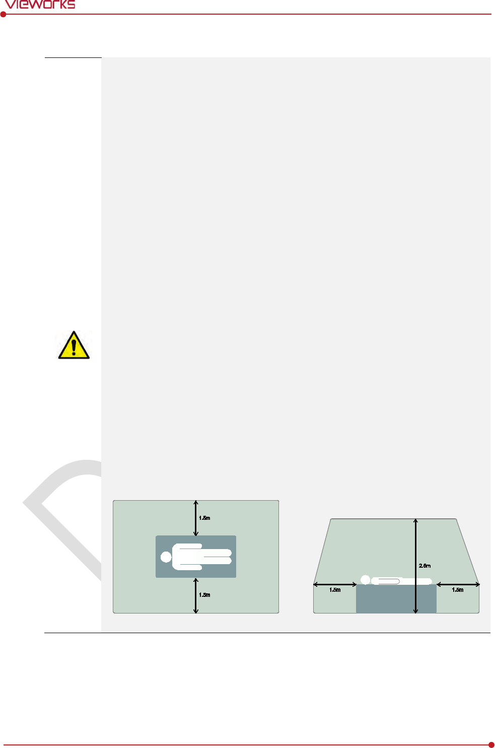
The battery charger and SCU (System Control Unit) cannot be used in patient’s vicinity.
Rev.1.0
Page 17 of 151 VW40-152-009
VIVIX-S 1012N User Manual
1.3.6 Problem Management
Should any of the following occur, immediately turn OFF the power to each piece of
equipment, unplug the power cord from the AC outlet, and contact sales representative or
distributor.
When there is smoke, an odd smell or abnormal sound no period.
When liquid is spilled into the equipment or a metal object is entered through an
opening.
When the equipment has been dropped and is damaged.
1.3.7 Maintenance and Inspection
Do not use or store the equipment near flammable chemicals such as acetone, benzene,
thinner, etc. If chemicals are spilled or evaporated, it may result in a fire or electric shock
through contact with electric parts inside the equipment.
If any flammable cleaning agent is used for the product, be sure to take care when using
them.
When the equipment is going to be cleaned, be sure to turn OFF the power of the
equipment and unplug the power cord from the AC outlet. Never use thinner, acetone,
benzene or any other flammable cleaning agent. Otherwise, it may result in a fire or
electric shock.
Clean the plug of the power cord periodically by unplugging it from the AC outlet and
removing dust or dirt from the plug, its periphery, and AC outlet with a dry cloth. If the
cord is kept plugged in for a long time in a dusty, humid or sooty place, dust around the
plug will attract moisture, and this could cause insulation failure that could result in a fire.
Be sure to turn OFF the power of the equipment while cleaning. Otherwise, a fire or
electric shock may occur.
Rev.1.0
Page 18 of 151 VW40-152-009
VIVIX-S 1012N User Manual
1.4 Product Usage Guide
When using the equipment, take the following precautions. Otherwise, problems may
occur and the equipment may not function correctly.
1.4.1 Calibration
To ensure optimal system performance, it is important to verify that the system is calibrated correctly.
Check if the calibration is performed after the equipment is completed to be installed or repaired.
Do not try to use the system if the calibration has not been performed.
You can process calibration with the calibration data CD (provided).
The calibration result can be different by the use environment. Therefore, if the result with
the provided calibration data is not satisfied, you can create the data at the field in
person by using VIVIX Setup, the calibration software.
1.4.2 Length Measurement
Before taking any length measurement on an image, carry out the length calibration with a reference
object and verify its results for correct measurement.
1.4.3 Left/Right Marker
The operator is responsible for making a correct and clear mark on the left or right side of the image.
The software includes a function to mark the image with L (left) or R (right) while acquiring the image
through printing and archiving.
Prepare an alternative way to prevent any confusion if the operator does not choose to use L/R marks.
1.4.4 Image Backup
To avoid missing images which might result in a patient being exposed to additional dose of radiation,
it is important to send images to PACS or backup images by using film or external storage media (CD,
DVD, HDD, USB).
If the hard disk of your workstation is about to be full, the operator should backup images to
somewhere else and delete them to make storage (memory) space in the hard disk for new patients.
The image backup should be done as a routine operation for every patient and image.

Rev.1.0
Page 19 of 151 VW40-152-009
VIVIX-S 1012N User Manual
1.4.5 Use Limitations
Vieworks software has the engineer mode operated by inputting the administrator password only.
This mode should be operated by the person who is qualified by Vieworks.
1.4.6 Disposal
Disposal of this product in an unlawful manner may have negative effects on human health and the
environment.
Be sure to follow the procedure which is in conformity with the laws and regulations applicable in your
area.
1.4.7 Pediatric Application
Every request should be reviewed by a pediatric radiologist prior to beginning the examination to
ensure that an appropriate study is being performed.
If the technologist notices an unusual request, he or she must contact a radiologist in charge.
Examples include orders- a Full Cervical, Thoracic, and Lumbar Spine series. The pediatric radiologist
should contact the ordering physician and decide which study is best for the pediatric patient.
The technologist should use a proper technique considering the patient’s size to decrease the
radiation dose when he or she acquires diagnostic images.
ALL pediatric patients shall be shielded for their X-ray examinations, except for when the shield will
obscure the region of interest, as in a pelvic or SI joint X-ray for trauma or arthritis, or when it is
physically or clinically unreasonable to shield the patient.
For routine Hip X-Rays, ALL male children shall have their scrotum shielded using the small gonadal
shield while females may not be shielded because doing so would obscure the hips.
To minimize motion in infants and young children, swaddle the infant. Use distraction tools to improve
cooperation and projectors with child-friendly themes, music, toys with flashing lights or music, child-
friendly images on the ceiling or walls, singing, counting, and a parent reading and talking to the child
through the console all can help reduce anxiety and comfort the child.
A scoliosis series will consist of a single frontal standing view of the spine. No lateral view or supine
view is needed, unless specifically asked for by the Orthopedist or Radiologist. If the female’s breasts
can be shielded without obscuring the spine, breast shields should be used.
1.4.8 Before Exposure
Be sure to check the equipment daily and confirm that it works properly.
Sudden heating of the room in cold areas will cause condensation to form on the equipment. In this
case, wait until the condensation evaporates before performing an exposure. If the equipment is used
while condensation is formed in it, problems may occur in the quality of captured images.
When an air-conditioner is used, be sure to raise/lower the temperature gradually so that difference
between the temperature in the room and in the equipment does not occur, to prevent condensation.

Rev.1.0
Page 20 of 151 VW40-152-009
VIVIX-S 1012N User Manual
1.4.9 During Exposure
This equipment is not protected (sealed) against liquids such as blood and medicine in the operating
room. If necessary, wrap the equipment in a disposable cover when using it.
Do not use the selected frequency channel (2.4 ㎓ and 5 ㎓ dual band) for other wireless devices.
Mutual interference may affect the image data transmission rate.
Do not use the detector near devices generating a strong magnetic field. Doing so may produce
image noise or artifacts.
1.4.10 Operating and Storage Environment
This equipment is mainly used in the X-ray exposure room and hospital wards. To use it in other
places, consult Vieworks’ sales representative or a distributor.
Do not expose this equipment to high temperatures and/or high humidity. Malfunctions may occur.
When not in use, keep the products in a safe location.
Be sure to use and store this equipment under the conditions described below.
Classification
Temperature
Humidity (Non
-condensing)
Atmos
phere
Operating Environment
+10 ~ +35
℃
30
~ 85%
700
∼ 1060 hPa
Storage Environment
-
15 ~ +55℃
10
~ 90%
500
∼ 1060 hPa
1.4.11 Others
Do not use this equipment in combination with peripherals such as defibrillators or large electric
motors as these may cause power-supply noise or power supply voltage variations. Doing so may
prevent normal operation of this equipment and peripherals.

Rev.1.0
Page 21 of 151 VW40-152-009
VIVIX-S 1012N User Manual
2. Product
This section gives an instruction about the product components and their specifications.
Overview
Product Components
VIVIX-S 1012N Detector
SCU
Battery Pack
Battery Charger
Others

Rev.1.0
Page 22 of 151 VW40-152-009
VIVIX-S 1012N User Manual
2.1 Overview
ViVIX-S 1012N detector is the digital X-ray imaging solution. It acquires images by exposing X-ray which
has been penetrated the human body. When X-ray photons pass through scintillator in the detector, the
photons convert to visible ray, and the visible ray is converted to electronic signals through TFT (a-Si). Then
the detector digitalizes x-ray images and transfers them to the computer (workstation) for radiography
diagnostics. Users can perform image diagnosis easily through the image display monitor with this process.
Advanced digital image processing also allows considerably efficient diagnosis, all kinds of information
management, and sharing of image information on network.
This detector is used for the general-purpose diagnostic procedures, and it is intended to
replace radiographic film / screen systems.
This detector is not intended for mammography applications.
2.1.1 Features
Since VIVIX-S 1012N detector is compatible with a conventional film cassette, it enables to replace
the analog radiographic diagnosis (Supporting ISO4090 standard).
The new sensor with 124μm pixel pitch produces high spatial resolution (approx. 5.2 Mega pixels)
digital images.
Various applications such as neonatal, ENT, equine and cephalo
Choose between two scintillator types (CsI and Gadox) of detector provided by Vieworks.
The built-in wireless communication supports IEEE 802.11n to acquire images without a wired
connection in anytime, anywhere.
Make direct wireless communication with the built-in wireless AP function. (Inside APTM)
Supports the stable and reliable AED (Auto Exposure Detection) function. (AnytimeTM)
Designed as lightweight and thin with portability to allow easy exposure in anytime, anywhere.
Used in various ways for infant / animals and in the dental clinic / ENT, etc.
Rev.1.0
Page 23 of 151 VW40-152-009
VIVIX-S 1012N User Manual
2.2 Product Components
2.2.1 Detector
Component
Description
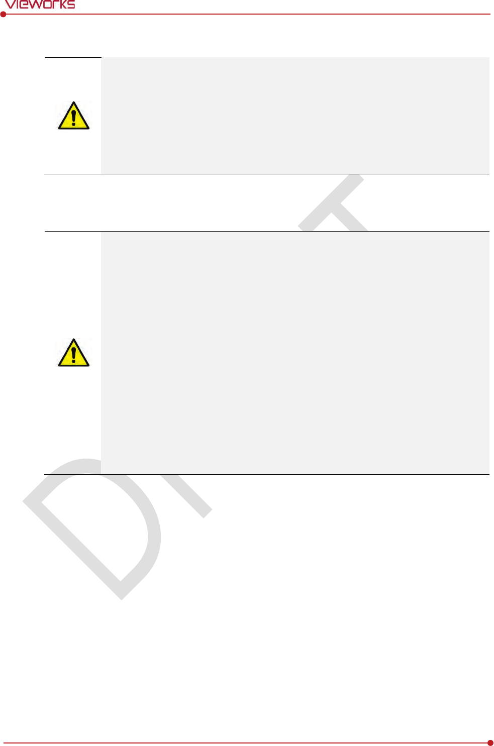
VIVIX
-S 1012N
Wireless Detector
FXRD-1012NAW (2.2kg)
FXRD-1012NBW (2.2kg)
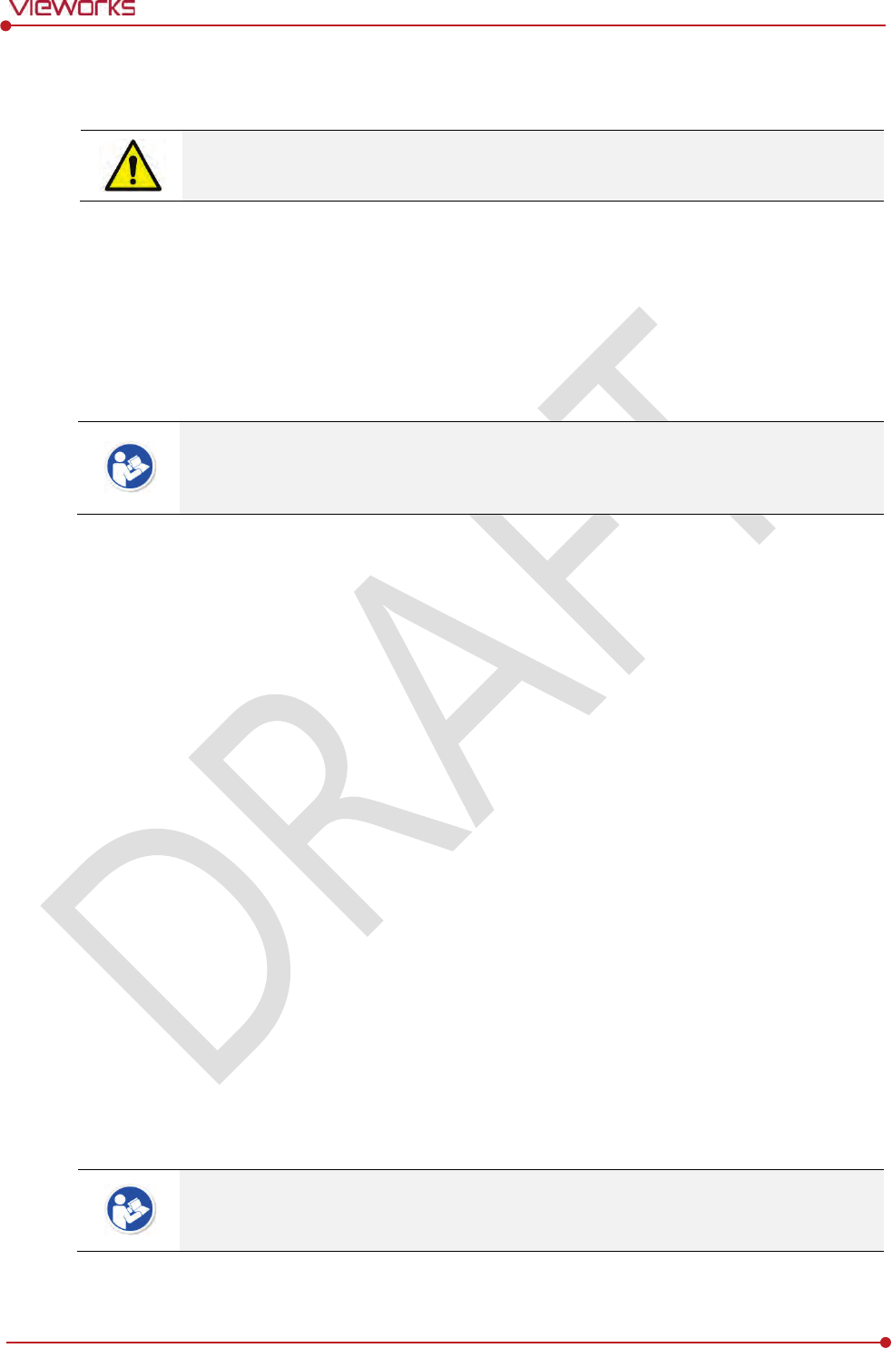
VIVIX
-S 1012N
Wired Detector
FXRD-1012NA (2.2kg)
FXRD-1012NB (2.2kg)
A deco sheet attached on the detector can be different depending on each client
company.
2.2.2 SCU (System Control Unit)
Component
Description
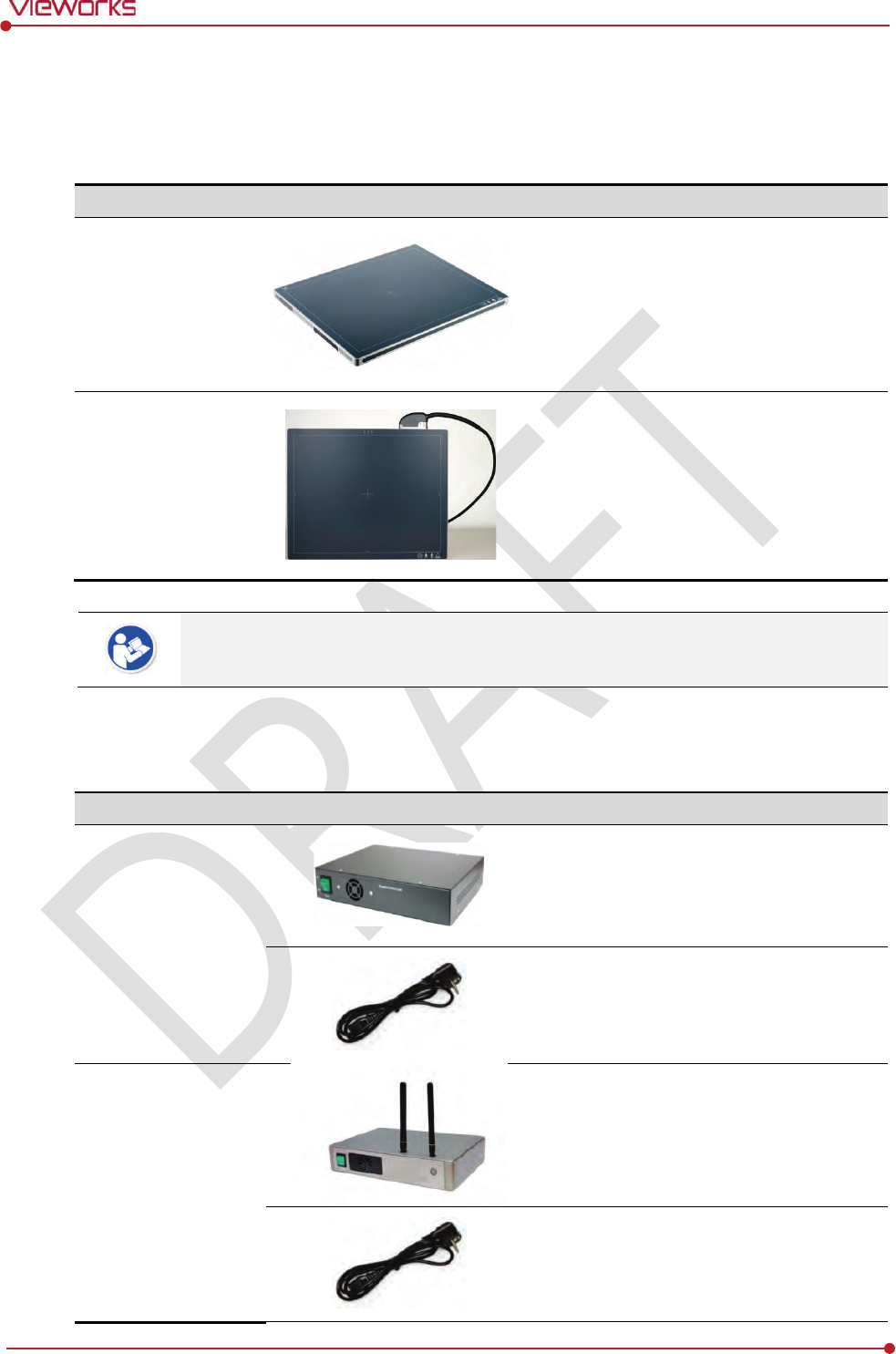
SCU Basic
(FXRS
-02A)
FXRS-02A (2.5kg)
AC Power Cable (2m)
SCU Basic
(FXRS
-03A)
FXRS-03A (2.8kg)
AC Power Cable (2m)
Rev.1.0
Page 24 of 151 VW40-152-009
VIVIX-S 1012N User Manual
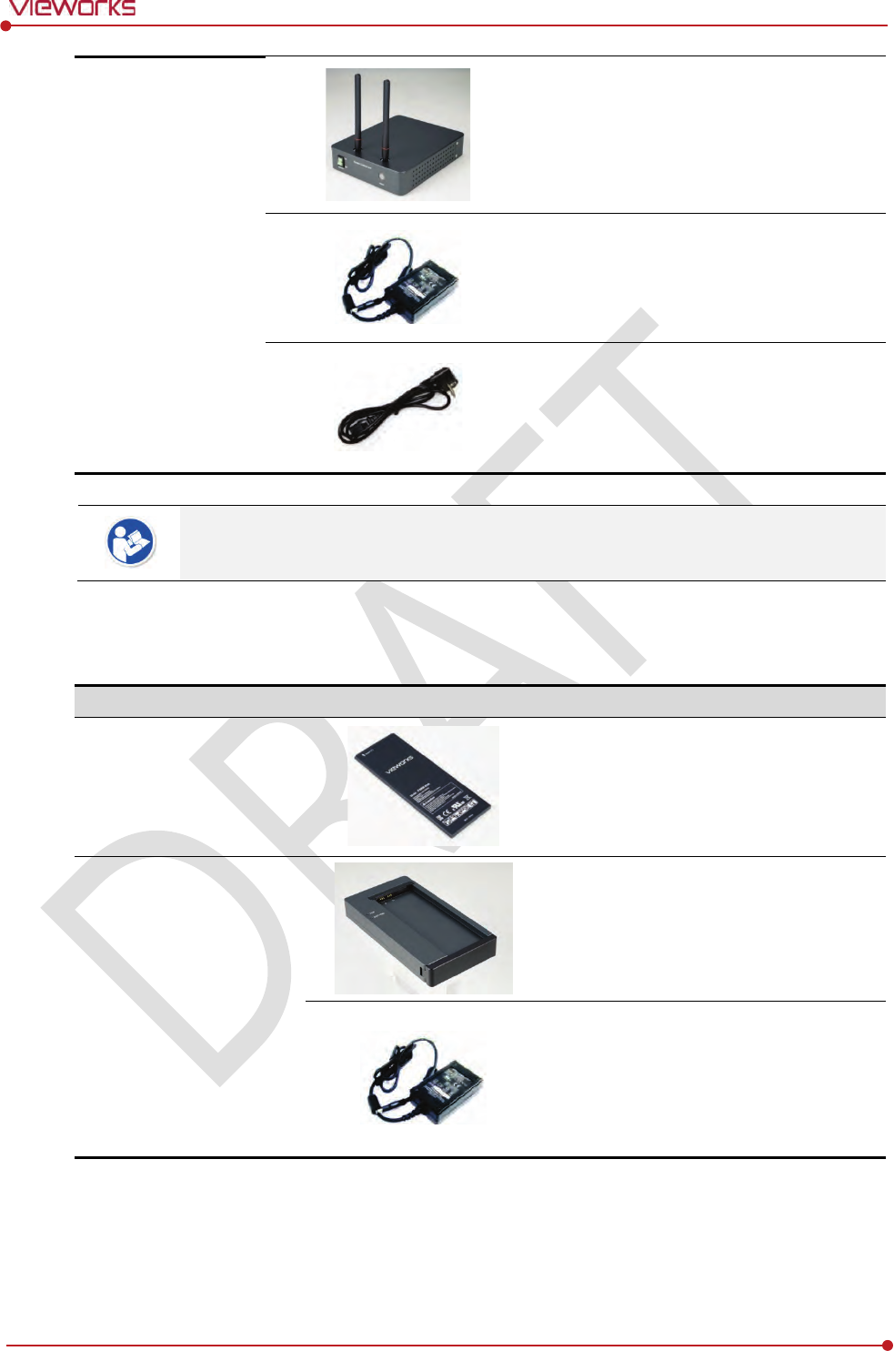
SCU mini
(FXRS
-04A)
FXRS-04A (1.2kg)
DC Power Supply (24V)
AC Power Cable (2m)
You can choose the type of SCU depending on the purpose of use.
2.2.3 Battery & Charger
Component
Description
Battery
FXRB-03A (0.12kg, 2EA)
Charger
FXRC-02A (0.8kg)
DC Power Supply (24V)
Rev.1.0
Page 25 of 151 VW40-152-009
VIVIX-S 1012N User Manual
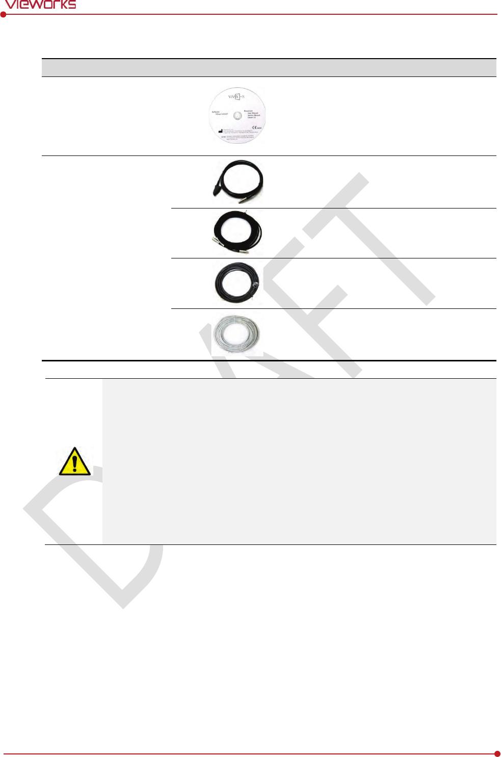
2.2.4 Accessaries
Component
Description
Resource
Software (Viewer or SDK)
Manuals
Cables
Tether Interface Cable (7m)
Ether Con Cable (7m, Option)
Generator Interface Cable (7m)
UTP LAN Cable (15m, Direct)
CAT 5E or CAT6
The use of accessories and cables other than those approved and sold by Vieworks Co.,
Ltd. may result in increased release of electromagnetic waves or decreased stability of the
equipment.
Accessory equipment connected to the analog and digital interfaces must be certified
according to the respective IEC standards. All combinations of equipment must be in
compliance with IEC 60601-1-1 system requirements.
Any person who connects additional equipment to the signal input or signal output ports
configures a medical system, and is therefore responsible for ensuring that the system
complies with the requirements of the system standard IEC 60601-1.
Consult your sales distributor or manufacturer if you have any concerns.

Rev.1.0
Page 26 of 151 VW40-152-009
VIVIX-S 1012N User Manual
2.3 VIVIX-S 1012N Detector
VIVIX-S 1012N is designed to acquire digital images by collecting x-ray signals and sereval conversion
processes. You can use the acquired image (10” x 12” film size) diversely depending on the purpose of use.
VIVIX-S 1012N is one of the VIVIX detector models produced by Vieworks.
2.3.1 Specifications
Item
Specifications
Model
FXRD-1012NA (CsI)
FXRD-1012NAW (CsI)
FXRD-1012NB (Gadox)
FXRD-1012NBW (Gadox)
Image
Sensor
TFT: a-Si (Amorphous Silicon)
X
-ray Scintillator Type
FXRD-1012NA(W) : Csl: TI (Thallium doped Caesuim Iodide)
FXRD-1012NB(W) : Gd2O2S:Tb (Gadolinium oxysulfide)
Pixel
Pitch
0.124㎜ (124㎛)
Field of
View
10” x 12”
Active
Area (H x V)
253.95㎜ × 317.44㎜
Active
Array
2048 x 2560 pixels
Effective
Area
252.5㎜ x 316.0㎜
Effective
Array
2036 x 2548
Grayscale
16bit
Spatial
Resolution
Min. 4.0 lp/㎜
Image
Acquisition Time (Wired)
1.5 sec.
Image
Acquisition Time (Wireless)
3 sec.
Recommended Cycle Time
15 sec.
X
-ray Synchronization Control
AED (Auto Exposure Detection)
DR Trigger (External line trigger)
Rated
Power Supply
DC +24V, Max. 0.8A
Wired: Powered by SCU with a tether interface cable.
Wireless: Powered by a battery pack (3,100 ㎃h)
Power
Consumption
Max. 19.2 W
Dimensions
(H × W × D)
287.0㎜ × 350.0㎜ × 15.0㎜
Weight
(including a battery pack)
2.2 kg
Image
Transfer
Wired: Gigabit Ethernet (1000BASE-T) via PoE (Power over
Ethernet)
Wireless: IEEE802.11n
Data
Transmission Rate (Wired)
Max. 1Gbps
Data
Transmission Rate (Wireless)
Max. 300Mbps (MIMO 2X2)
Rev.1.0
Page 27 of 151 VW40-152-009
VIVIX-S 1012N User Manual
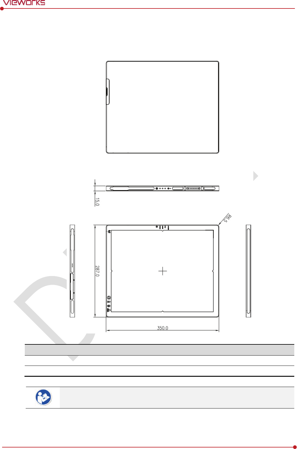
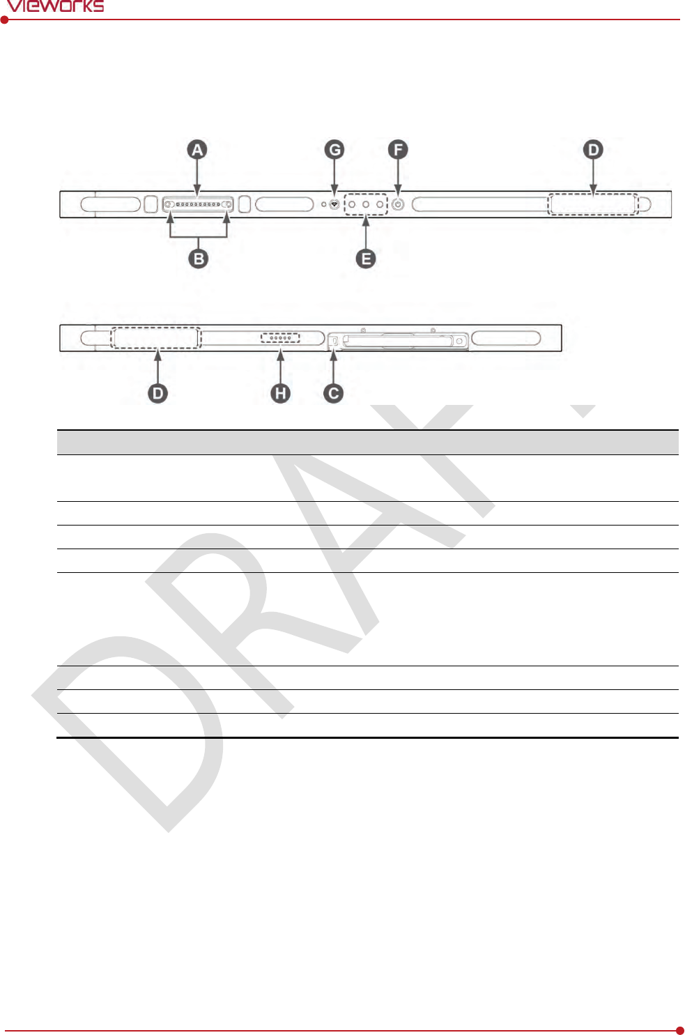
2.3.2 Drawing Sheet
VIVIX-S 1012NAW / 1012NBW (Wireless Detector)
Item
Description
Dimensions
(H × W × D)
287.0
㎜ × 350.0㎜ × 15.0㎜
Curvature of Edges
R6.5
Under the ISO4090 regulation, the allowed tolerance of a thickness of detector is from -
2㎜ ~ +1㎜.
Rev.1.0
Page 28 of 151 VW40-152-009
VIVIX-S 1012N User Manual
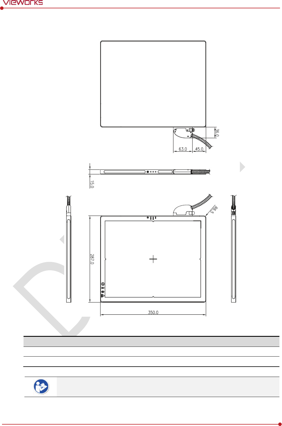
VIVIX-S 1012NA / 1012NB (Wired Detector with a tether interface cable)
Item
Description
Dimensions
(H × W × D)
287.0
㎜ × 350.0㎜ × 15.0㎜
Curvature of Edges
R6.5
Under the ISO4090 regulation, the allowed tolerance of a thickness of detector is from -
2㎜ ~ +1㎜.
Rev.1.0
Page 29 of 151 VW40-152-009
VIVIX-S 1012N User Manual
2.3.3 Functions
VIVIX-S 1012NAW / 1012NBW (Wireless)
Name
Description
A
T
ether interface connector
Used for tighten the tether interface cable.
Used for wired connection between a detector and SCU.
B
Tether interface holder
Fix/release holder of the tether interface cable.
C
B
attery lock lever
Lock/unlock lever of the equipped battery pack.
D
Antenna for wireless LAN
Antennas for wireless communication (2EA)
E
Status indicator
Detector status indicator
DATA LED (Blue): Indicates communication and transmission
ACTIVE LED (Orange): Indicates ready to work
POWER LED (Green): Indicates power On/Off status
F
Power button
Detector power button
G
AP ON /OFF Button
Turns on / off the AP mode.
H
Battery Remaining LED
Notices the remaining of battery in 5 levels.

Rev.1.0
Page 30 of 151 VW40-152-009
VIVIX-S 1012N User Manual
VIVIX-S 1012NA / 1012NB (Wired)
Name
Description
A
T
ether interface connector
Used for tighten the tether interface cable.
Used for wired connection between a detector and SCU.
B
Tether interface holder
Fix/release holder of the tether interface cable.
C
Status indicator
Detector status indicator
DATA LED (Blue): Indicates communication and transmission
ACTIVE LED (Orange): Indicates ready to work
POWER LED (Green): Indicates power On/Off status
D
Power button
Detector power button
Rev.1.0
Page 31 of 151 VW40-152-009
VIVIX-S 1012N User Manual
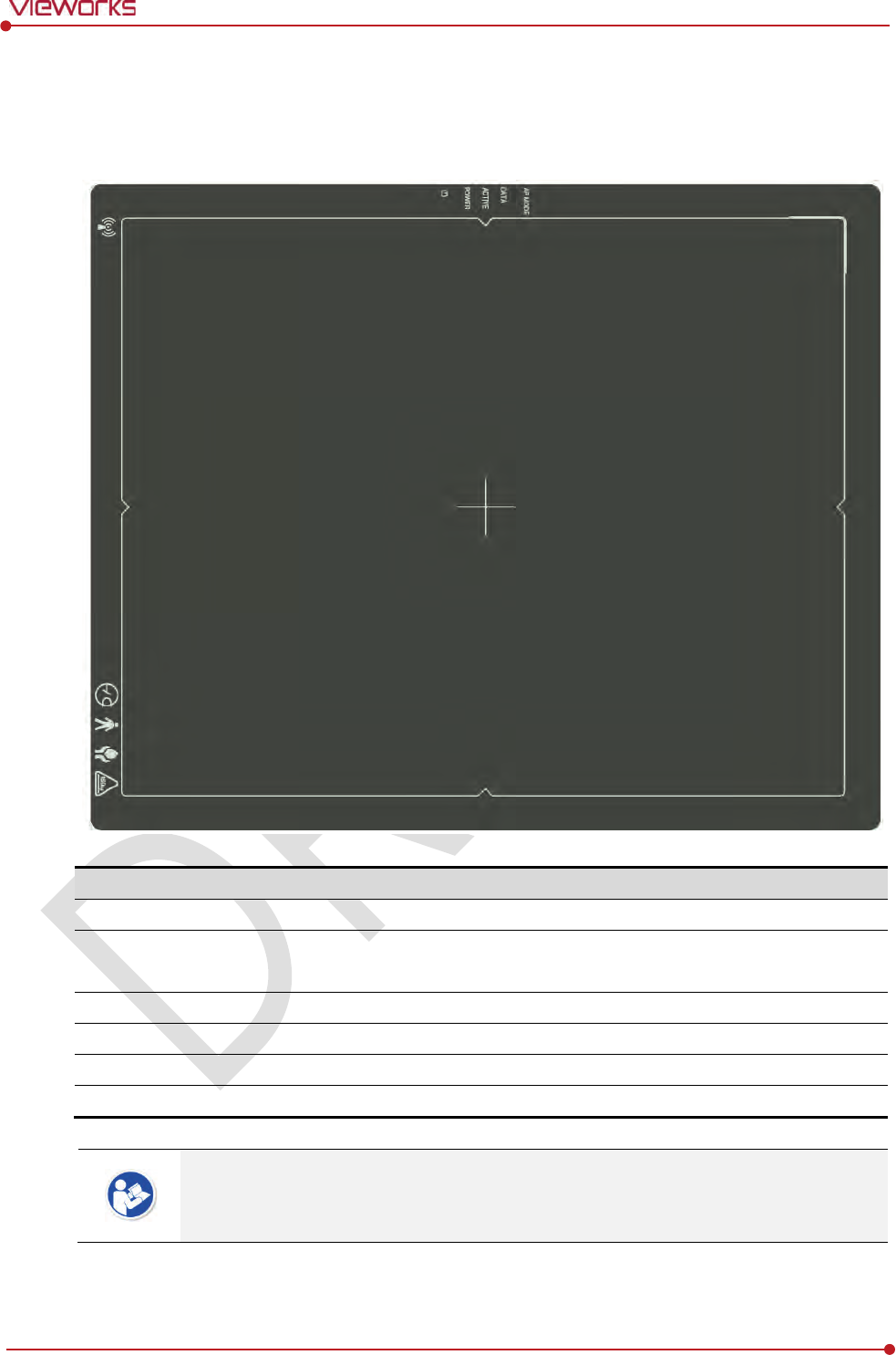
2.3.4 Deco Sheet
VIVIX-S 1012NAW / 1012NBW (Wireless)
Indication
Info.
Description
A
Wireless communication l
ogo
Indicates that this model
can be operated wirelessly.
B
Status indication l
ogo
Indicates the operating state of detector
.
AP Mode, DATA, ACTIVE, POWER
C
Image starting p
oint
Indicates the starting point of an original image.
D
C
enter of the detector
Indicates the central position of
detector.
E
Vieworks logo
Indicates the logo of Vieworks.
F
Certification logo
Indica
tes the certification logos relating to a medical device.
Image starting point (0.0) of this detector is located nearby the tether interface connector.
You can change the displayed direction of an image from the VIVIX Setup program, but
it does not mean that the starting point and direction of the original image are changed.
Rev.1.0
Page 32 of 151 VW40-152-009
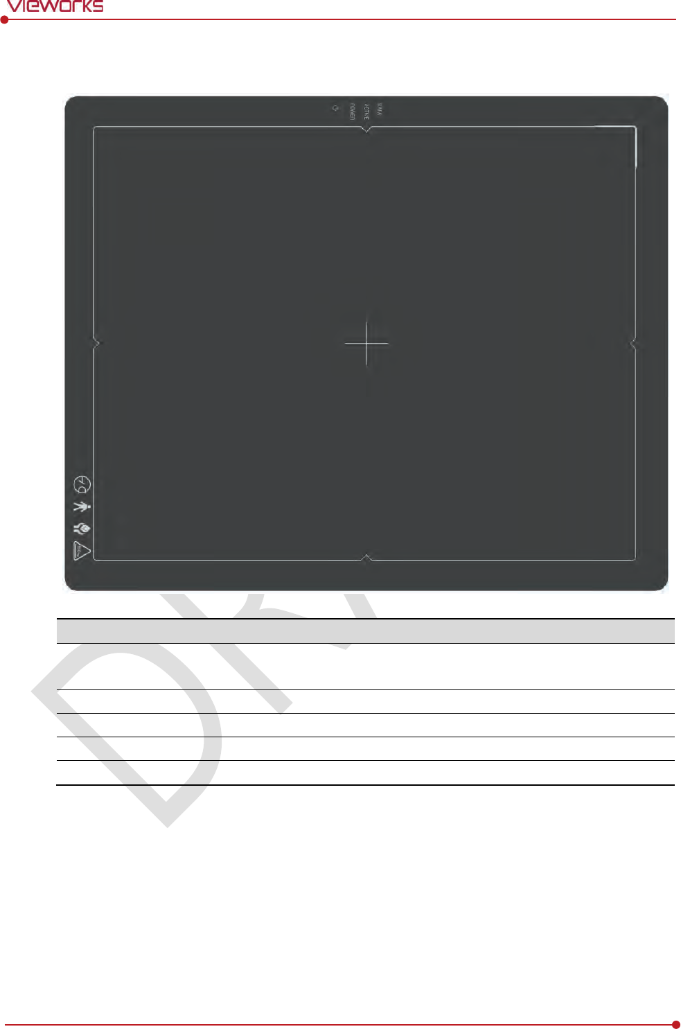
VIVIX-S 1012N User Manual
VIVIX-S 1012NA / 1012NB (Wired)
Indication Info.
Description
A
Status indication
logo
Indicates the operating state of detector.
DATA, ACTIVE, POWER
B
Image starting point
Indicates the starting point of an original image.
C
Center of the detector
Indicates the central position of detector.
D
Vieworks logo
Indicates the logo of
Vieworks.
E
Certification logo
Indicates certification logos relating to a medical device.
Rev.1.0
Page 33 of 151 VW40-152-009
VIVIX-S 1012N User Manual
2.3.5 Wireless Communication
Item
Specifications
Wireless standard
IEEE802.11n
Frequency range
2.412 ~ 2.472
㎓ (13 Channels)
5.18 ~ 5.24
㎓ (4 Channels)
5.745 ~
5.805㎓ (4 Channels)
Data transmission rate
802.11n: Max. 300Mbps (MIMO 2X2)
Modulation
BPSK, QPSK, 16
-QAM, 64-QAM
Transmission power
Max. 17dBm
Security
WPA2
-PSK
Antenna
Dual Band Antennas (2EA, inbuilt)
The specification of detector and SCU are same, but the location of antenna is different.
2.3.6 Use Environment
Item
Operation
Storage
& Transportation
Temperature
+10 ~ +35℃
-
15 ~ +55℃
Humidity
30 ~ 85% (Non
-condensing)
10 ~ 90% (Non
-condensing)
Atmospheric pressure
700 ~ 1060 hPa
500 ~ 1060
hPa
Shock
1.6G
20G
Vibration
0.7G
0.7G
The use environment of detector and SCU is same.
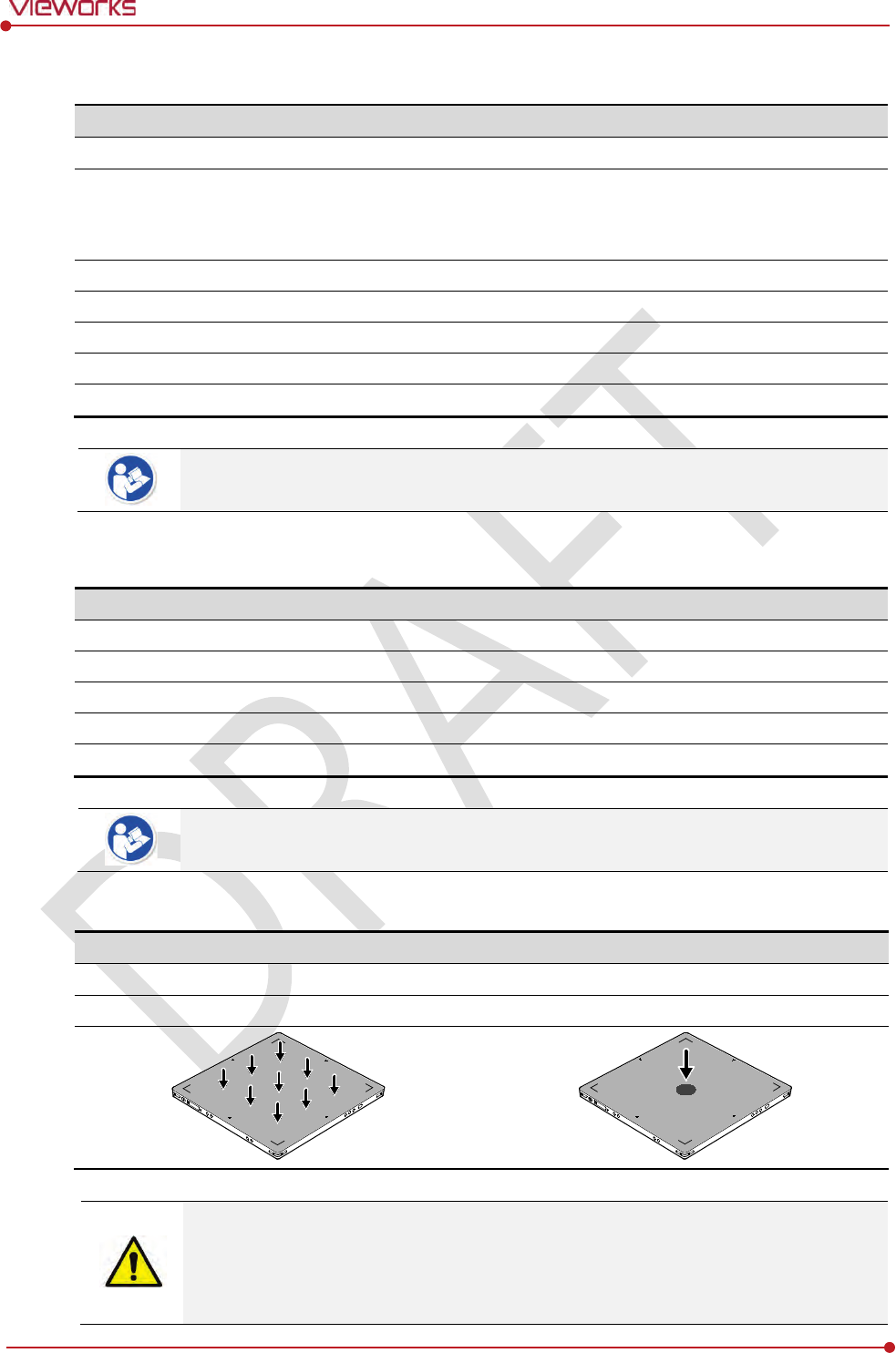
Load Limit of Detector
Uniform load
Local load
Over the whole surface Center diameter 40mm
Max. 100 kg Max. 150 kg
Do not let the paitent or object heavier than load limit be on the detector. Then, detector
can be damaged.
Do not let the patient lie or get on the detector. Internal devices such as a sensor can be
seriously damaged even if his/her weight is within the load limit.
Rev.1.0
Page 34 of 151 VW40-152-009
VIVIX-S 1012N User Manual
2.4 SCU Basic (FXRS-02A)
SCU synchronizes the image and X-ray signal as locating among the detector, workstation and the X-ray
generator. You can use the SCU directly when the power supplies to SCU after connecting it under the
VIVIX-S 1012N system environment.
2.4.1 Specifications
SCU
Item
Specifications
Model
FXRS-02A
Power Supply
Input: AC100 to 240V, 50/60㎐, Max. 200VA
Output: DC +24V 3.3A, 80W
Cable Connection port
Gigabit Ethernet ports (3ea)
Two(2) PoE (Power over Ethernet) ports
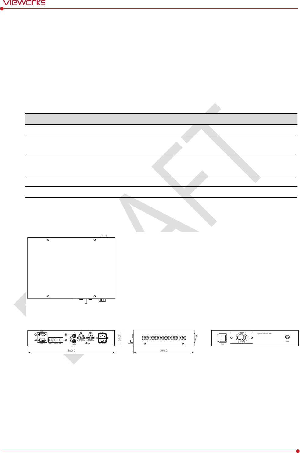
Dimension
(H × W × D)
210.0 ㎜ × 300.0 ㎜ × 54.2 ㎜
Weight
2.5 ㎏
2.4.2 Drawing Sheet
Rev.1.0
Page 35 of 151 VW40-152-009
VIVIX-S 1012N User Manual
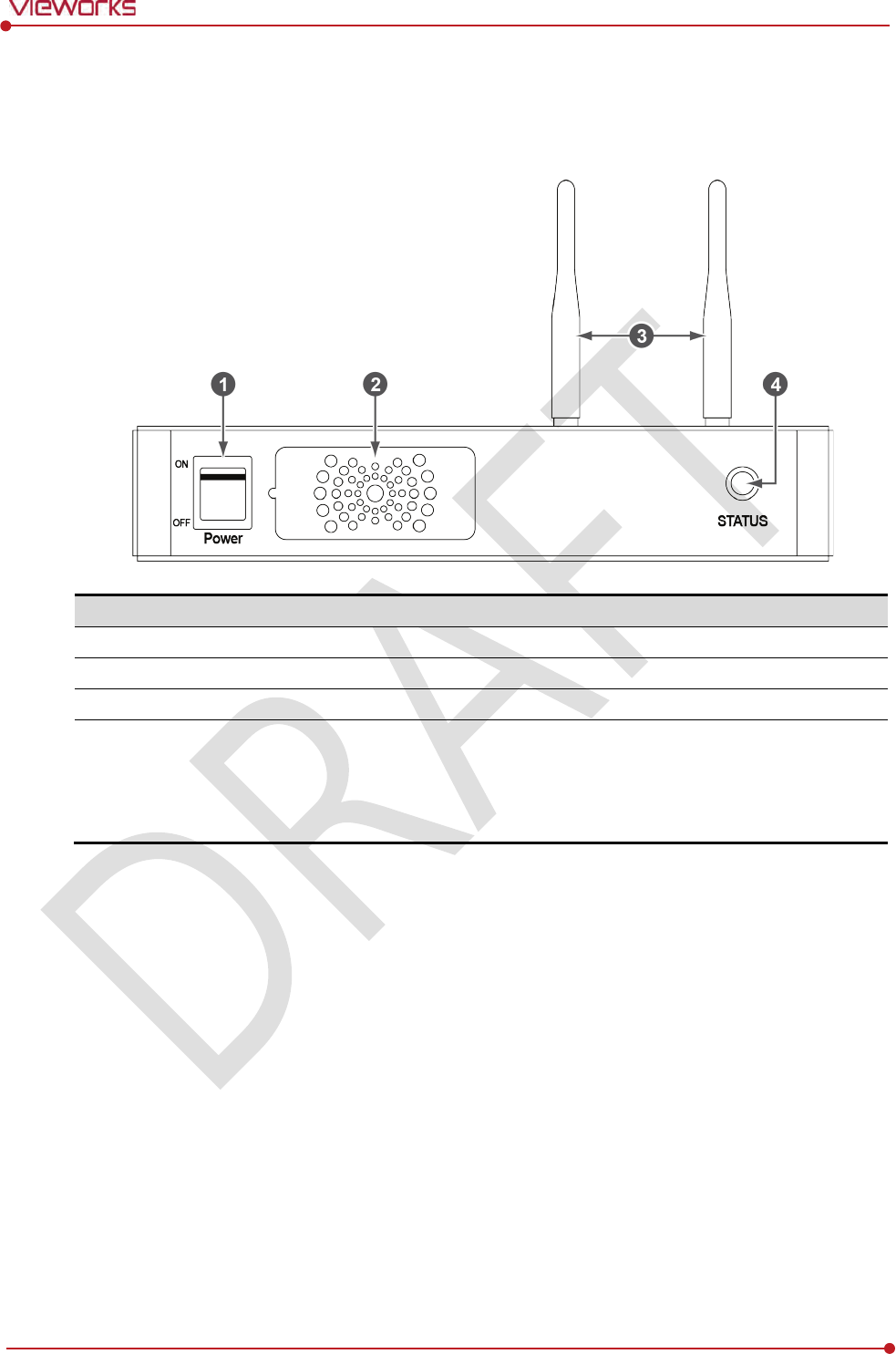
2.4.3 Functions
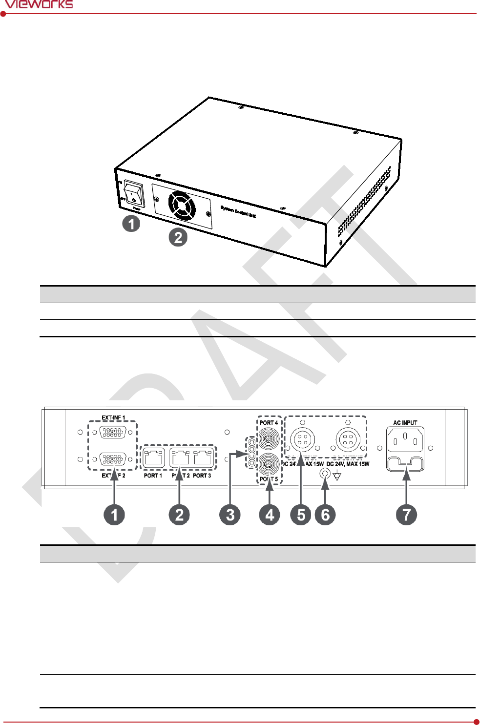
Front Side
No.
Name
Description
1
Power Switch
SCU power swtich (ON or OFF) (Including green LED Lamp)
2
Fan
Expels interior air of SCU
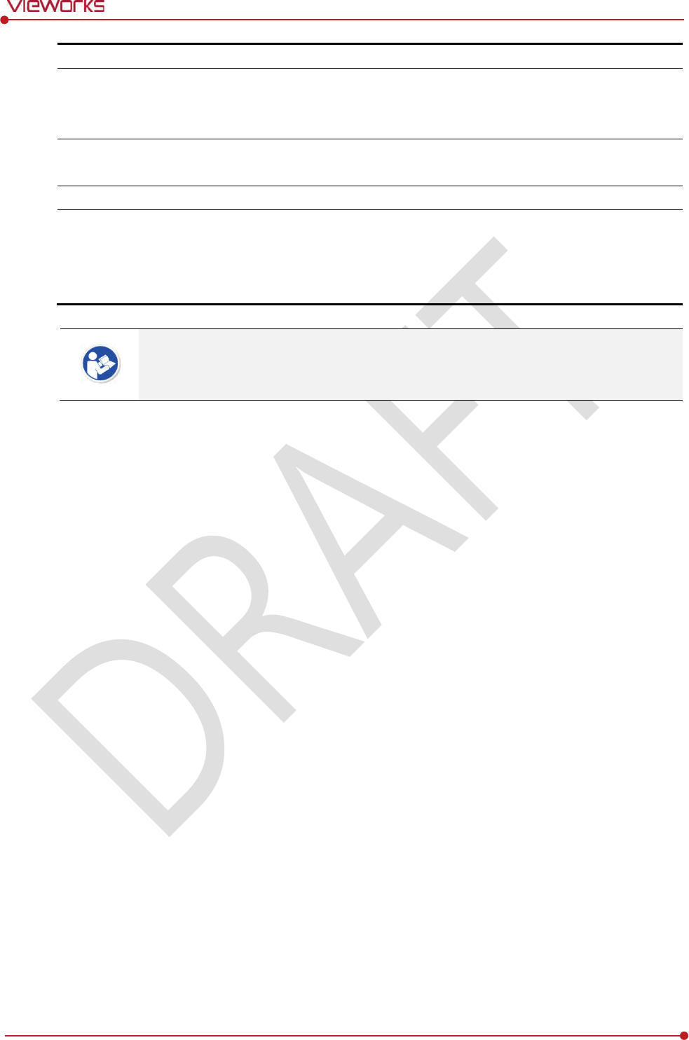
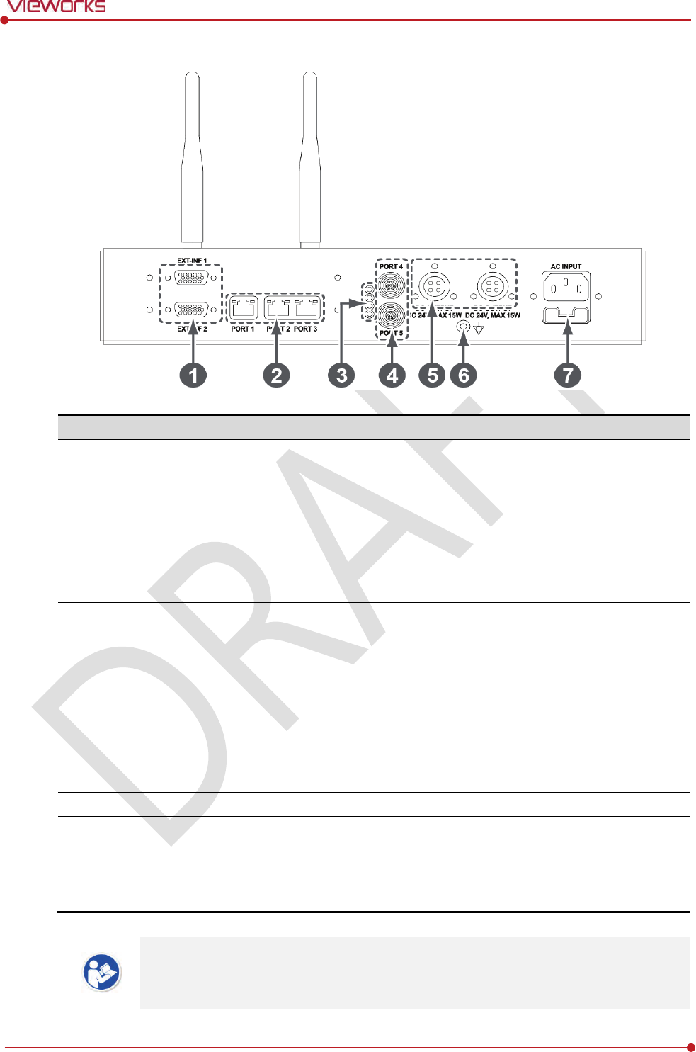
Rear Side
No.
Name
Description
1
EXT_INF
1
EXT_INF2
X
-ray generator interface connector (D-SUB 15 pins x 2 EA, Female)
EXT_INF1 : 1 ~ 15
EXT_INF2 : 16 ~ 30
2
LAN port
(Port 1, 2, 3)
Gigabit Ethernet port (1000BASE
-T)
Port 1: Communicates between workstation and SCU Basic.
Port 2, 3: Communicates between FXRD-1717S detector and SCU
Basic when configuring multiple detectors.
3
PoE status lamp
Indicates the status of
PoE port (Port 4, Port 5)
Green: 1 Gbps
Rev.1.0
Page 36 of 151 VW40-152-009
VIVIX-S 1012N User Manual
Orange: 100 Mbps
4
PoE port
(
Port 4, 5)
PoE
(Power over Ethernet) port (1000BASE-T)
Communicates between the detector and SCU Basic.
Supplies power to the detector.
5
Detector power supply port
Max.
DC +24V/15W (2 ports)
For FXRD-1717S detector only.
6
P.E
E
quipotential ground
7
AC input port
T2AL250V
fuse (2 EA)
100 ~ 240V
50/60㎐
Supplies power to SCU Basic.
The P.E (Potential Equalization) port of SCU is used to maintain potential equalization
between SCU and another grounded system. Use the conductor that can be detached
without the use of a tool.
Rev.1.0
Page 37 of 151 VW40-152-009
VIVIX-S 1012N User Manual
2.5 SCU Basic (FXRS-03A)
SCU Basic synchronizes the image and X-ray signal as locating among the detector, workstation and the X-
ray generator. You can use the SCU Basic directly when the power supplies to SCU Basic after connecting it
under the ViVIX-S 1012N system environment
2.5.1 Specifications
Item
Specifications
Model
FXRS-03A
Power supply
Input: AC100 to 240V, 50/60㎐, Max. 200VA
Output: DC +24V 3.25A, 78W
Cable connection port
Gigabit Ethernet port (3EA)
PoE (Power over Ethernet) Port (2EA)
Wireless
communication
IEEE 802.11n (2.4 ㎓ / 5 ㎓)
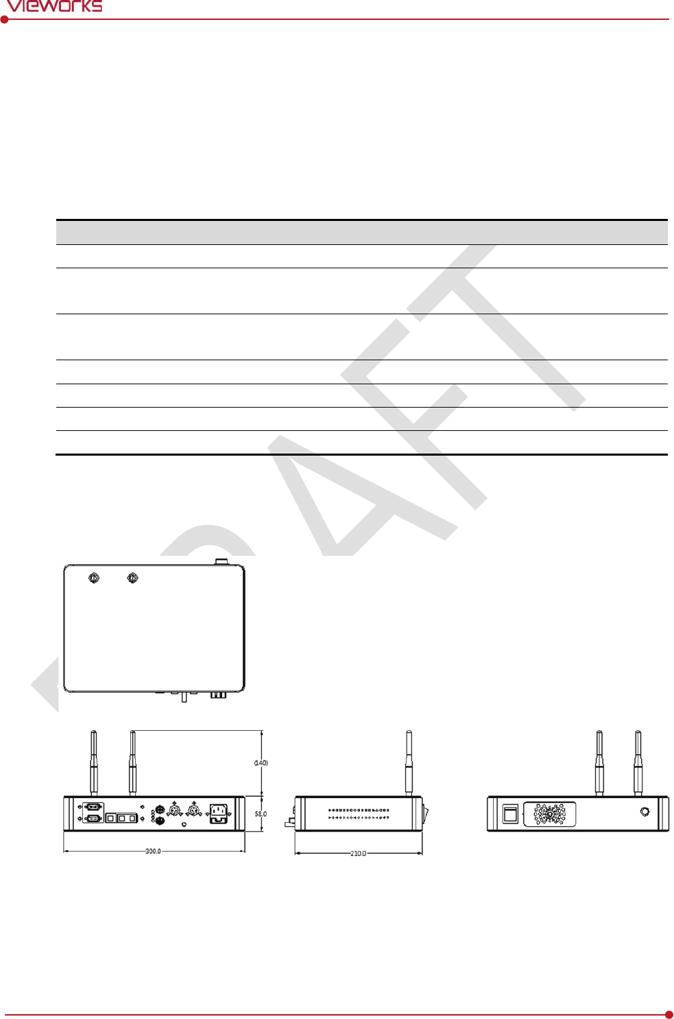
Dimension
(H × W × D)
236.0 ㎜ × 300.0 ㎜ × 58.0 ㎜
Antenna
105 ㎜ (2EA, Dual band)
Weight
2.8 ㎏
2.5.2 Drawing Sheet
Rev.1.0
Page 38 of 151 VW40-152-009
VIVIX-S 1012N User Manual
2.5.3 Functions
Front Side
No.
Name
Description
1
Power switch
Turn
s on/off the power of SCU Basic. (Including Green LED Lamp)
2
Fan
Expels the air
inside of SCU Basic.
3
Antenna
Assists
communications between the detector and SCU Basic.
4
Status LED
I
ndicates the operation and connection status of SCU Basic.
Blinking green: Booting
Green: Completed to boot up
Blue: The software is connected and ready to communicate.
Rev.1.0
Page 39 of 151 VW40-152-009
VIVIX-S 1012N User Manual
Rear Side
No.
Name
Description
1
EXT_INF
1
EXT_INF2
X
-ray generator interface connector (D-SUB 15 pins x 2 EA, Female)
EXT_INF1 : 1 ~ 15
EXT_INF2 : 16 ~ 30
2
LAN port
(Port 1, 2, 3)
Gigabit Ethernet port (1000BASE
-T)
Port 1: Communicates between workstation and SCU Basic.
Port 2, 3: Communicates between FXRD-1717S detector and SCU
Basic when configuring multiple detectors.
3
PoE status lamp
Indicat
es the status of PoE port (Port 4, Port 5)
Green: 1 Gbps
Orange: 100 Mbps
4
PoE port
(
Port 4, 5)
PoE
(Power over Ethernet) port (1000BASE-T)
Communicates between the detector and SCU Basic.
Supplies power to the detector.
5
Detector power supply port
Max.
DC +24V/15W (2 ports)
For FXRD-1717S detector only.
6
P.E
E
quipotential ground
7
AC input port
T2AL250V
fuse (2 EA)
100 ~ 240V
50/60㎐
Supplies power to SCU Basic.
The P.E (Potential Equalization) port of SCU is used to maintain potential equalization
between SCU and another grounded system. Use the conductor that can be detached
without the use of a tool.
Rev.1.0
Page 40 of 151 VW40-152-009
VIVIX-S 1012N User Manual
2.6 SCU mini (FXRS-04A)
SCU mini synchronizes the image and X-ray signal as locating among the detector, workstation and the X-
ray generator. You can use the SCU mini directly when the power supplies to SCU mini after connecting it
under the VIVIX-S 1012N system environment
2.6.1 Specifications
Item
Specifications
Model
FXRS-04A
Power supply
Input: DC +24V 2A Max
Cable
connection port
Gigabit Ethernet port (3EA)
PoE (Power over Ethernet) Port (1EA)
Wireless communication
IEEE 802.11n (2.4 ㎓ / 5 ㎓)
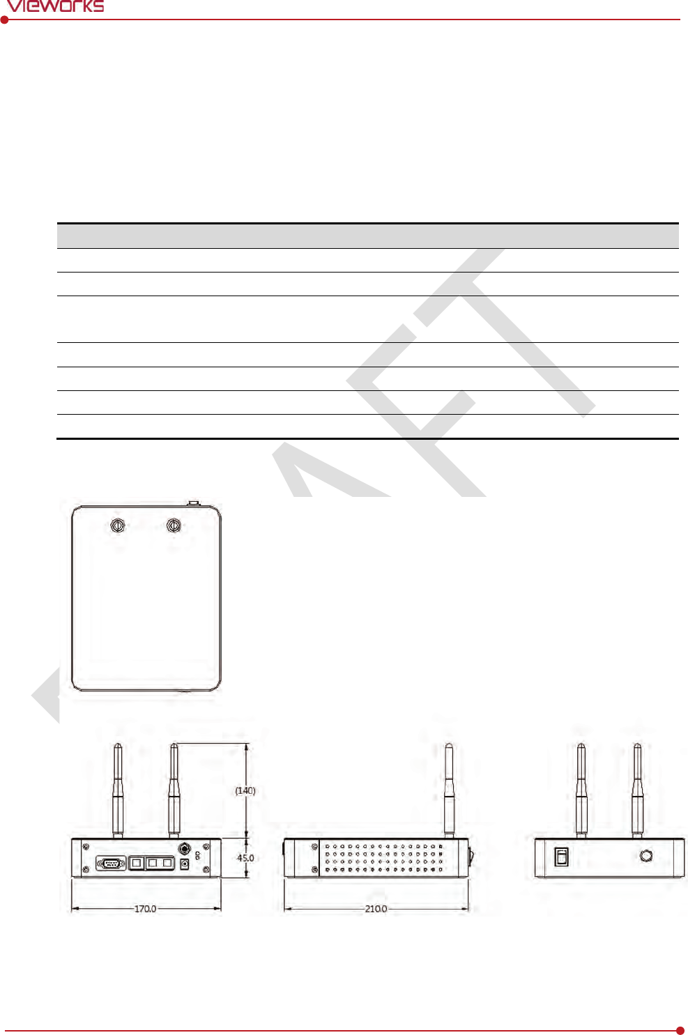
Dimension
(H × W × D)
211.5 ㎜ × 170.0 ㎜ × 45.0 ㎜
Antenna
105 ㎜ (2EA, Dual band)
Weight
1.2㎏
2.6.2 Drawing Sheet
Rev.1.0
Page 41 of 151 VW40-152-009
VIVIX-S 1012N User Manual
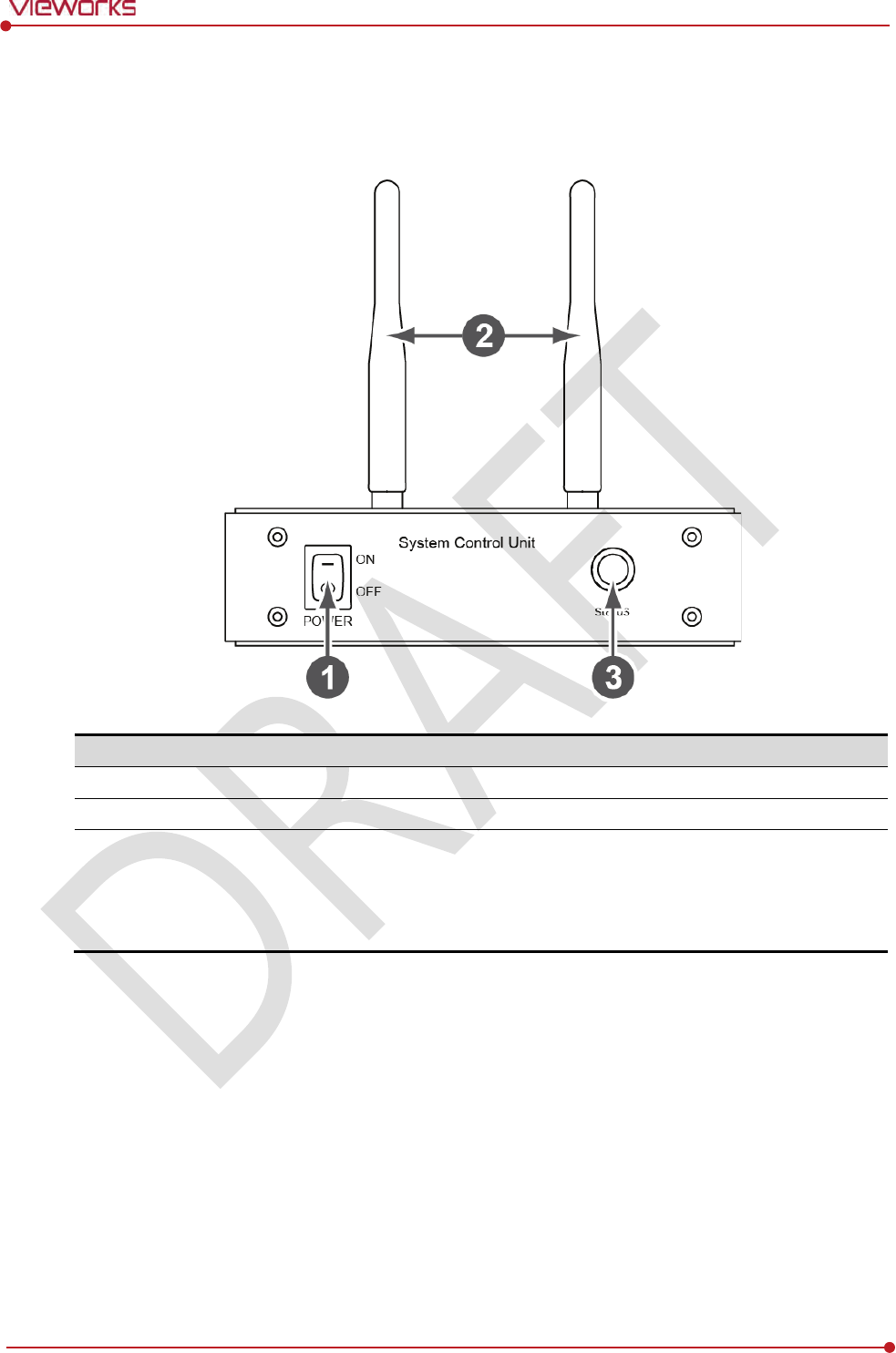
2.6.3 Functions
Front Side
No.
Name
Description
1
Power switch
Turn
s on/off the power of SCU mini. (Including Green LED Lamp)
2
Antenna
Assists
communications between the detector and SCU mini.
3
Status LED
I
ndicates status of SCU mini operation and connection.
Blinking green: Booting
Green: Completed to boot up
Blue: The detector is connected and ready to communicate.
Rev.1.0
Page 42 of 151 VW40-152-009
VIVIX-S 1012N User Manual
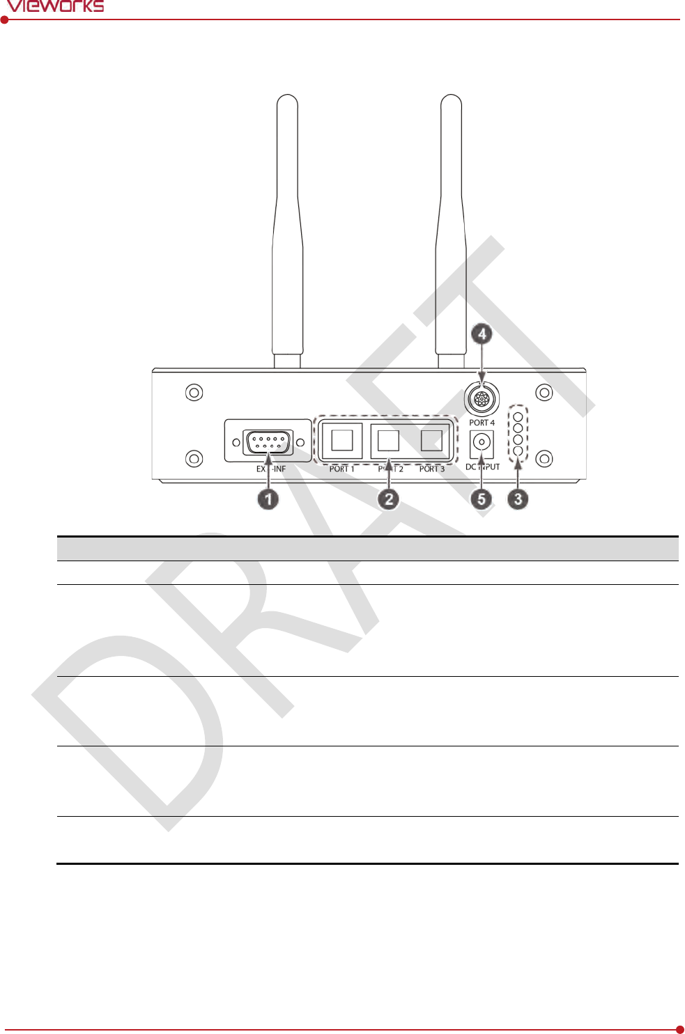
Rear Side
No.
Name
Description
1
EXT_INF
X
-ray generator interface connector (D-SUB 15pin, Female)
2
LAN port
(Port
1, 2, 3)
Gigabit Ethernet port (1000BASE
-T)
Port 1: Communication between the workstation and SCU mini.
Port 2, 3: Communication between FXRD-1717S detector and SCU mini
when configuring multiple detectors.
3
PoE status lamp
Indicats the status of
PoE port.
Green: 1 Gbps
Orange: 100 Mbps
4
PoE port
PoE
(Power over Ethernet) port (1000BASE-T)
Communication between the detector and SCU mini.
Supplies power to the detector.
5
DC power input port
DC +24V
Supplies power to SCU mini.
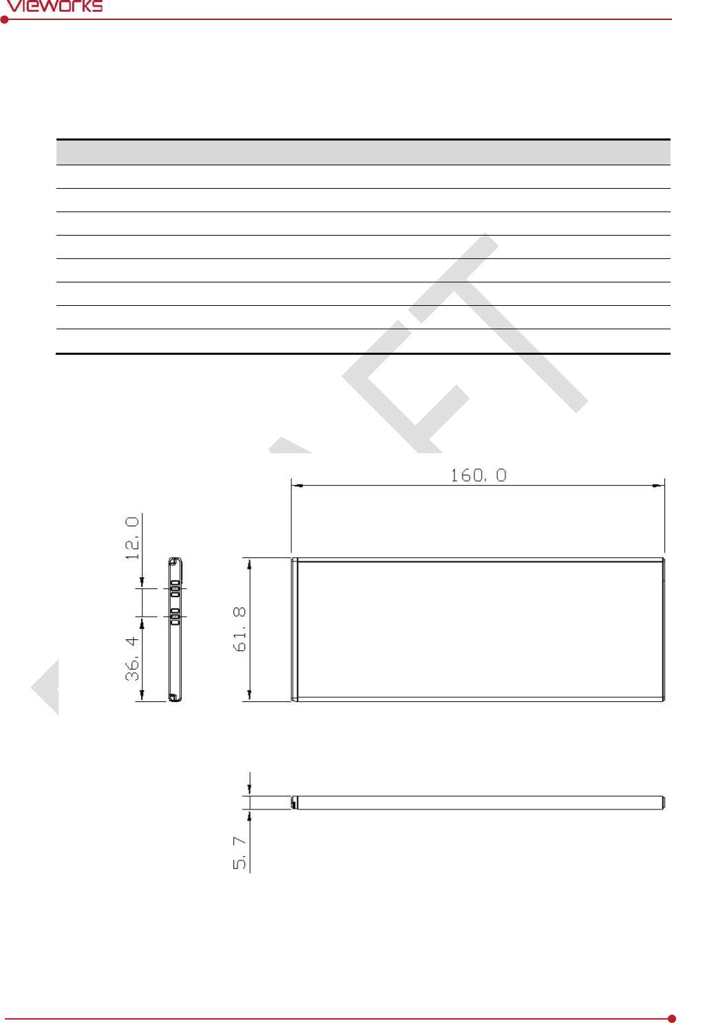
Rev.1.0
Page 43 of 151 VW40-152-009
VIVIX-S 1012N User Manual
2.7 Battery Pack
2.7.1 Specifications
Item
Specifications
Model
FXRB
-03A
Type
Lithium
Ion
Rated Power Supply
Output
: DC +7.6V
Capacity
3,1
00㎃h
Number of c
ell
2S1P (2 Series 1 Parallel)
Life
Approx. 500 times (Fully charged/Discharged completely, 1cycle)
Dimension
(H × W × D)
1
60.0 ㎜ × 61.8 ㎜ × 5.7 ㎜
Weight
11
5g
2.7.2 Drawing Sheet
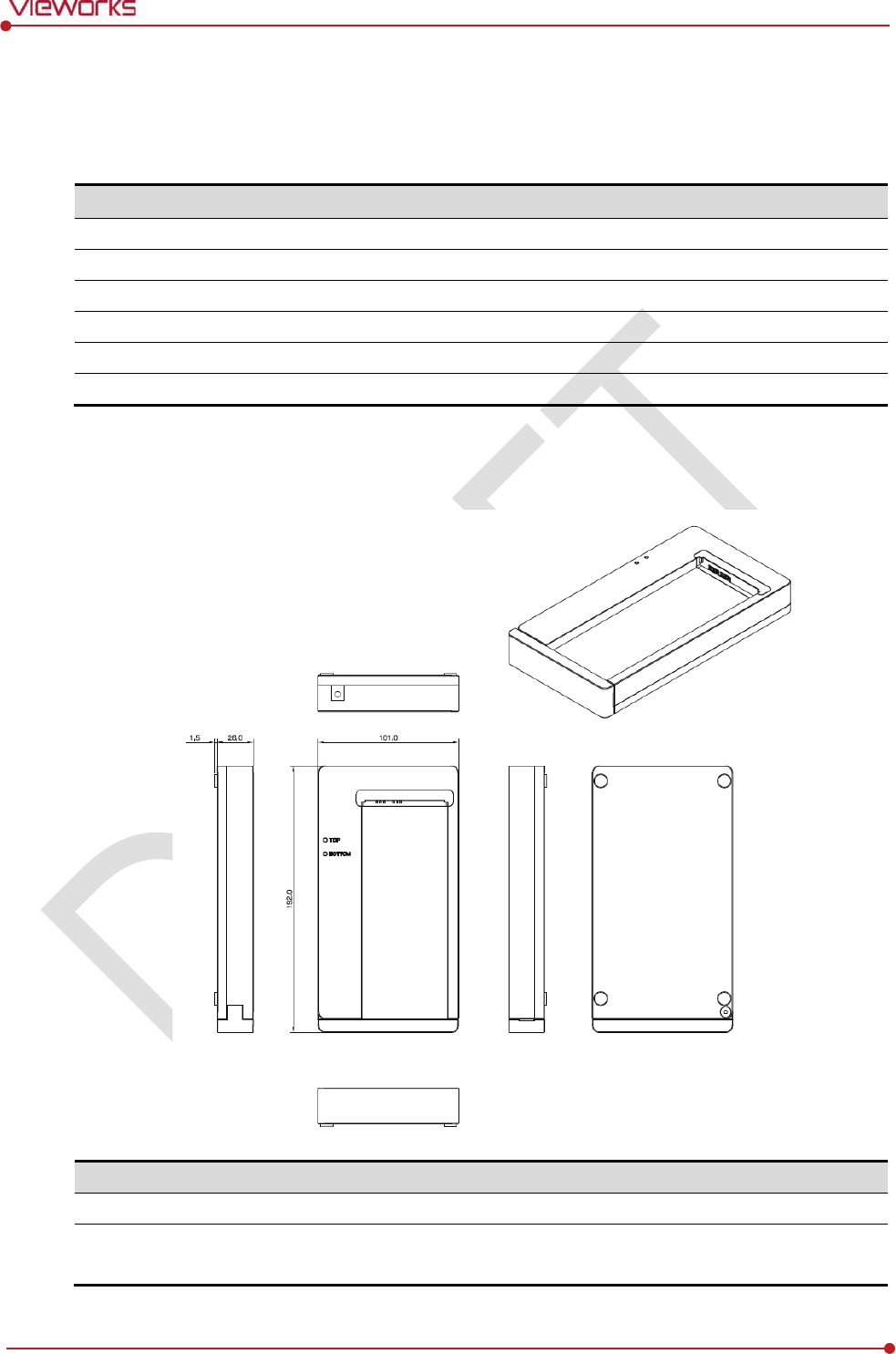
Rev.1.0
Page 44 of 151 VW40-152-009
VIVIX-S 1012N User Manual
2.8 Battery Charger
2.8.1 Specifications
Item
Specifications
Model
FXRC
-02A
Simultaneous Charging
2 battery packs
Charging time
3
hours
Rated power supply
DC +24V, 2
A Max.
Dimension
(H × W × D)
1
92.0 ㎜ × 101.0 ㎜ × 26.0 ㎜
Weight
0.8
㎏
2.8.2 Drawing Sheet
No.
Name
Description
1
Top / Bottom LED
Indicates the position and status of a battery being charged.
2
Power input port
Supplies electric power by connecting a power adapter to the
battery
charger
.

Rev.1.0
Page 45 of 151 VW40-152-009
VIVIX-S 1012N User Manual
2.9 Others
2.9.1 X-ray Generator (Recommended Exposure Condition)
Item
Recommended c
ondition
X
-ray energy range
40kVp ~ 150kVp
Reliability (Lifetime Dose)
74Gy or higher (35 uGy x 365days x 24hrs x 60min. x 60sec. / 15sec.)
2.9.2 Recommended Specifications of Workstation (PC)
Item
Recommended specification
Operating System
VIVIX Setup
Microsoft Windows 7 (32bit / 64bit)
Microsoft Windows 7 64bit SP1 (Professional Edition or higher)
Microsoft Windows Vista Service pack 1 or higher (32bit / 64bit)
Microsoft Windows 8 (32bit / 64bit) / 8.1 64bit SP1 (Professional
Edition or higher
Microsoft Windows 8.2 (32bit / 64bit)
CPU
Intel Core i5 2600 or higher (or compatible CPU)
Memory
4GB or higher
Hard Disk
1TB or higher
LAN Card
(only for
detector communication)
Gigabit (for detector only)
Intel® PRO 1000 Series (Gigabit LAN Card for network interface)
Min.requiremetns
Speed: 1Gbps or more
Jumbo Frames: 9K
Receive Descriptors: 2K (1024 or higher)
Monitor
1024 x 768 or more
CD
-ROM
CD or DVD R/W
2.9.3 Recommended Specifications of Grid
Item
Recommended specification
SID
100cm / 130cm / 150cm / 180cm
Size
451mm x 365mm x 1.5mm
Ratio
8.1 / 10:1 / 12:1
Frequency
215 line/inch
INTER SPACER
AL
Check the recommended specifications by Vieworks first before buying the generator,
workstation and grid.

Rev.1.0
Page 46 of 151 VW40-152-009
VIVIX-S 1012N User Manual
3. System Configuration
This section gives information about the various connection / configuration ways among the
detector, SCU, workstaton and X-ray generator.
You can figure out the most suitable way of system configuration through this instruction.
Detector Connection Method
Diagram
System Configuration
Generator Interface
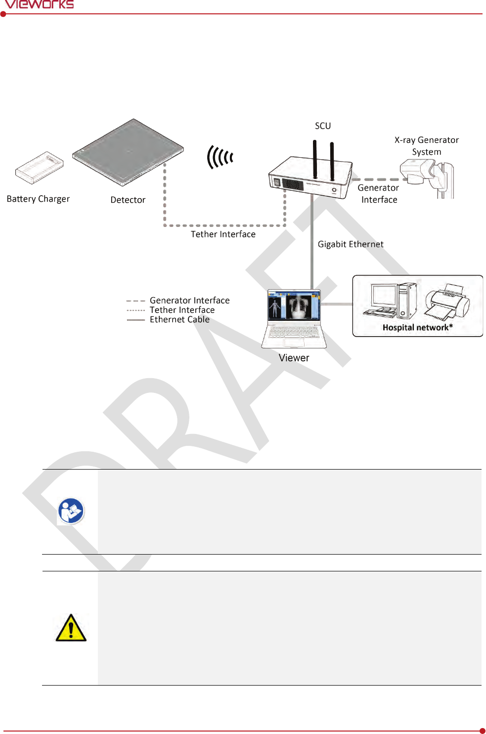
Rev.1.0
Page 47 of 151 VW40-152-009
VIVIX-S 1012N User Manual
3.1 Detector Connection Methods
You can organize wired or wireless connection between the VIVIX-S 1012N detector and SCU. You can also
choose other connection ways suitable for the use environment in case of need.
3.1.1 Wireless Connection
The images and data are transmitted between the VIVIX-S 1012N detector and SCU by wireless
connection.
A battry pack should be installed in the detector to use it under the wireless configuration.
We recommend you to use the wireless connection method for the following cases.
When using the unfixed detector.
When the wired communication is in trouble by the interruption of cables.
The wireless connection is more freely to operate than the wired connection.
Use the wireless connection with a laptop computer to enhance mobility.
Be sure to operate the wireless commnunication between the detector and SCU within a
maximum of 8m.
Use of multiple WLAN devices within the same frequency band may interfere with each
wireless communication and cause a decline in transmission speed.
Do not cover or block the wireless module of the detector. Also, do not put any shielding
materials between the detector and SCU. Otherwise, the transmission speed or operable
distance may be reduced.

Rev.1.0
Page 48 of 151 VW40-152-009
VIVIX-S 1012N User Manual
3.1.2 Wired Connection
Connect VIVIX-S 1012N detector and SCU with a tether interface cable to make a wired configuration.
As the tether interface cable supplies power to the detector, a battery pack is not needed to be
installed in the detector.
We recommend you the wired connection method for the following cases.
When continuous power supply to the detector is needed.
When the detector is fixed in a bucky stand or on a table.
When you upgrade the detector firmware or change the inner configural information.
When you need the data communication to be faster than the wireless connection.
A battery pack in the detector keeps charging under the wired connection.
The wireless communication module of the detector maintains inactivation status.
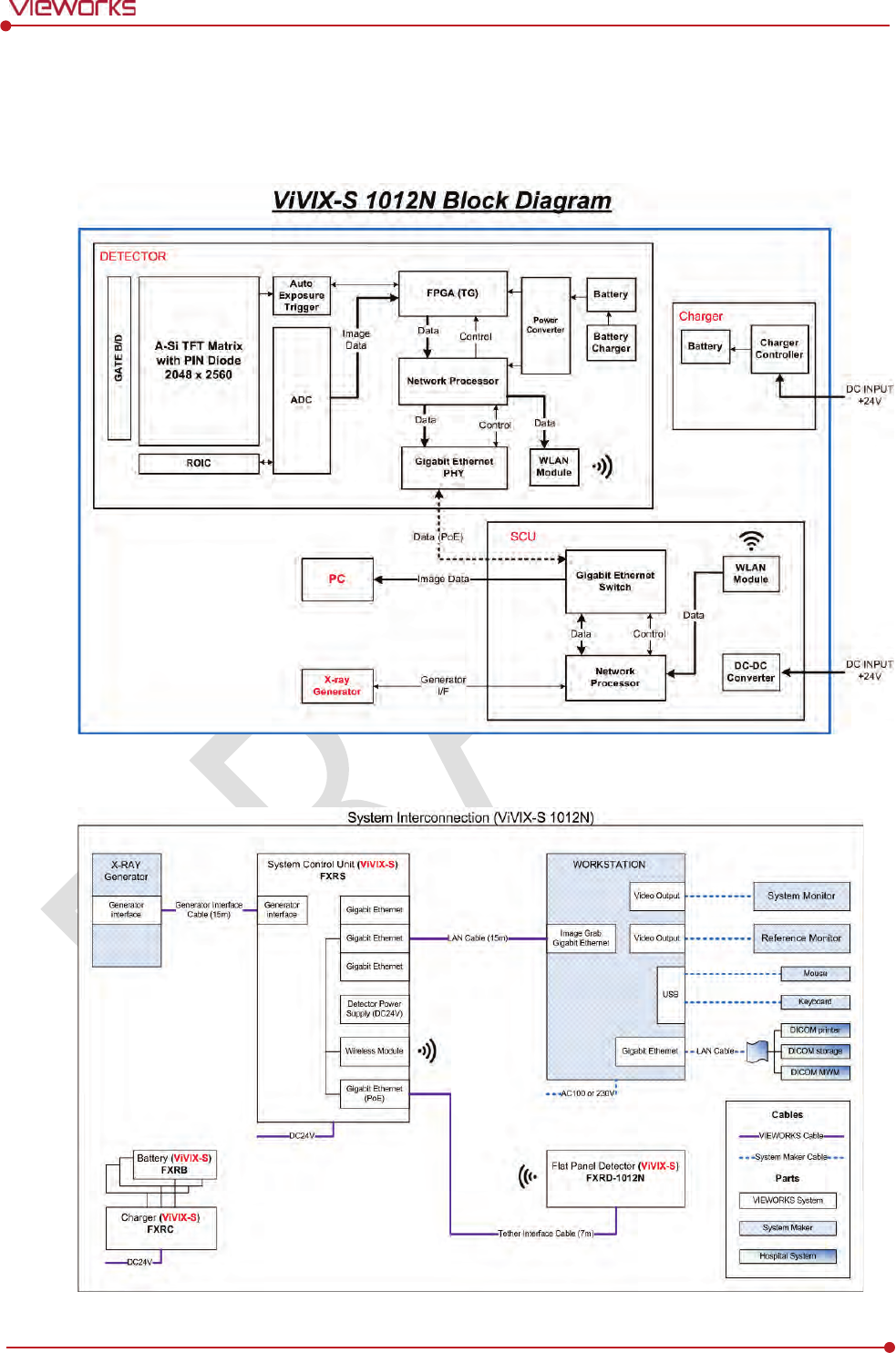
Rev.1.0
Page 49 of 151 VW40-152-009
VIVIX-S 1012N User Manual
3.2 Diagram
3.2.1 Block Diagram
3.2.2 Wiring Diagram
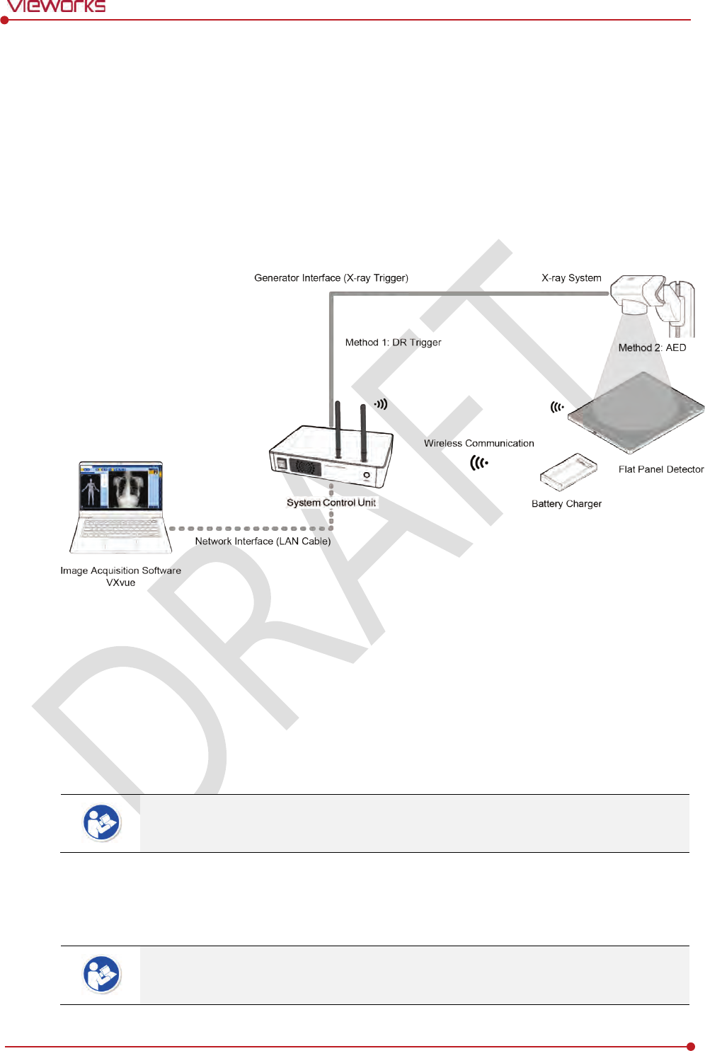
Rev.1.0
Page 50 of 151 VW40-152-009
VIVIX-S 1012N User Manual
3.3 System Configuration
This section gives information about the configuration modes of VIVIX-S 1012N detector, SCU, workstation
and the generator.
3.3.1 AP Mode (SCU AP Mode)
SCU AP mode is the wireless connection method that connecting the detector with SCU as the center
wirelessly.
SCU & Detector
The VIVIX-S 1012N detector and SCU are connected wirelessly. In this case, SCU and the detector
operate as AP (Access Point) and STATION respectively.
SCU & PC (Workstation)
SCU and PC (Workstation) are connected with the LAN cable.
It is available to connect SCU and PC wirelessly. In this case, SCU and the detector
operate as AP (Access Point) and STATION respectively.
SCU & Generator
SCU and the generator can be connected with the generator interface cable.
It is unnecessary to connect SCU and the generator with a generator interface cable if
you use AED mode of the detector.
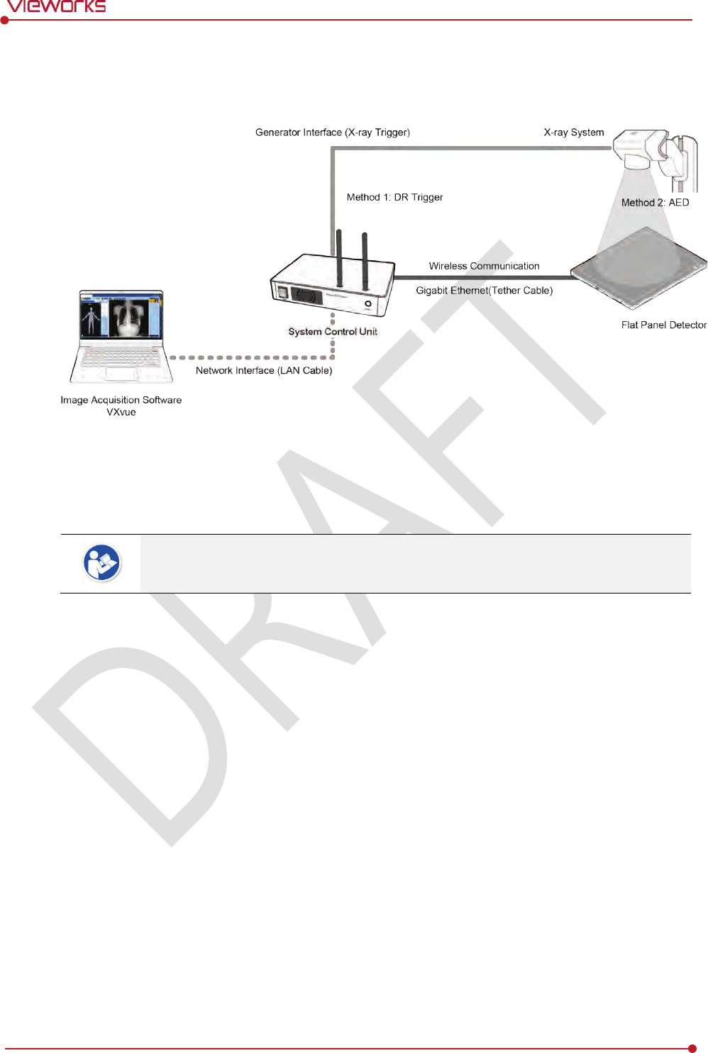
Rev.1.0
Page 51 of 151 VW40-152-009
VIVIX-S 1012N User Manual
3.3.2 Tether Interface Mode
Tether interface mode is the wired connection method that connecting the detector with SCU as the center.
SCU & Detector
SCU and the VIVIX-S 1012N detector are connected with the tether interface cable.
Other connection ways of the tether interface mode are the same as the AP mode.
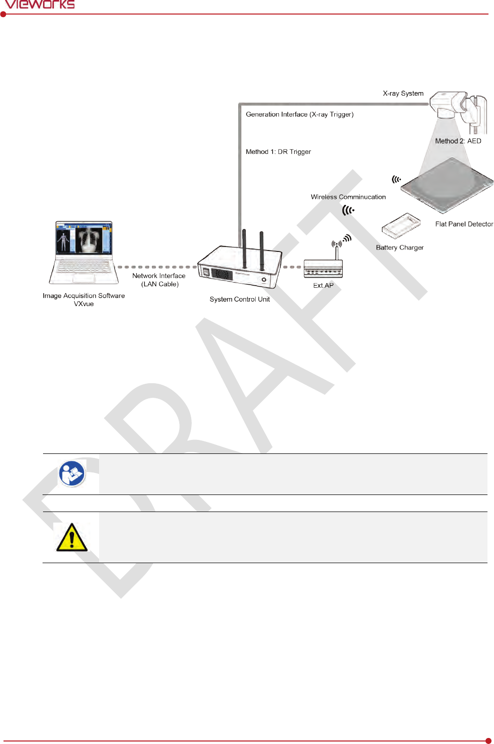
Rev.1.0
Page 52 of 151 VW40-152-009
VIVIX-S 1012N User Manual
3.3.3 External AP Mode
External AP mode is the wireless connection method that adding the external AP device instead of SCU.
External AP & SCU
The external AP and SCU are connected with a LAN cable.
External AP & Detector
The external AP and VIVIX-S 1012N detector are connected wirelessly. In this case, the external AP
and the detector operate as AP (Access Point) and STATION respectively.
Other connection ways of the tether interface mode are the same as the AP mode.
Be sure to check the specifications of external AP device when configuring the external
AP mode, since the wireless communication performance can be different by the
specifications.
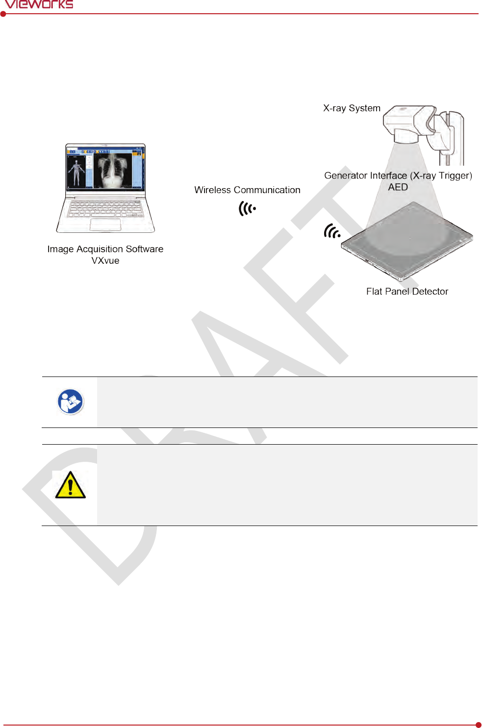
Rev.1.0
Page 53 of 151 VW40-152-009
VIVIX-S 1012N User Manual
3.3.4 Detector AP Mode
Detector AP mode is the wireless connection method that connecting the PC (Workstation) with the
detector as the center wirelessly.
Detector & PC (Workstation)
The VIVIX-S 1012N detector and PC are connected wirelessly. In this case, the detector and the PC
operate as AP (Access Point) and STATION respectively.
Since SCU is not used for configuring the detector AP mode, you can only use the AED
mode without a wired connection. (Cannot use the DR Trigger mode.)
This mode can be used when mobility and portability are needed.
When configuring the detector AP mode, be sure to check the specifications of wireless
module installed in the PC. The wireless communication performance can be different
depending on the specifications of the wireless module.
If the wireless connection cannot be made normally because of unexpected problems,
SCU can be needed to check the detector condition.
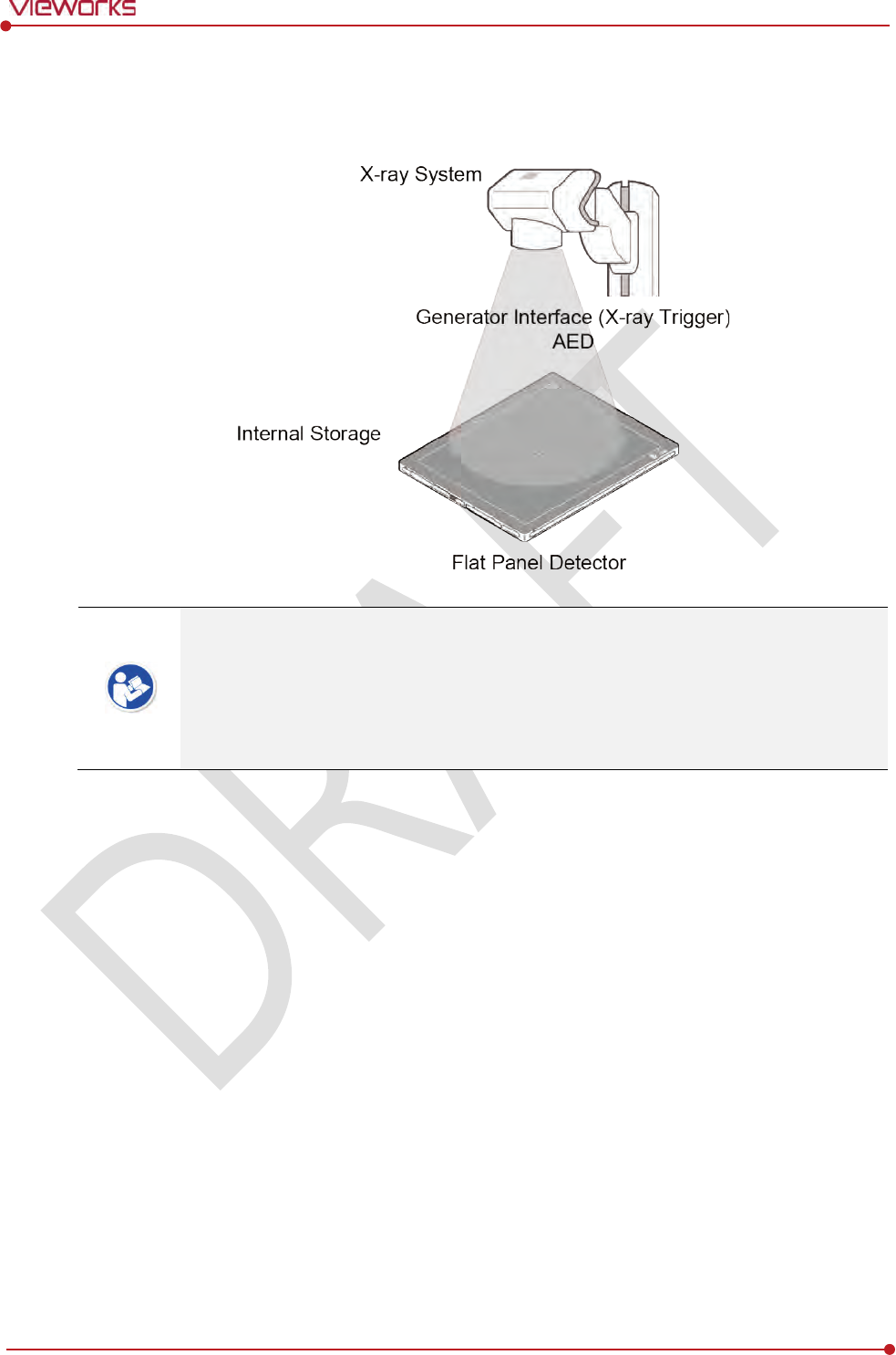
Rev.1.0
Page 54 of 151 VW40-152-009
VIVIX-S 1012N User Manual
3.3.5 Detector Stand-Alone Mode
You can use the Stand-Alone mode without making a wired or wireless connection.
You should take images with the AED mode only when using the Stand-Alone mode.
(Cannot use the DR Trigger mode.)
The acquired images are stored in the internal storage of the detector in order and the
images can be transmitted to the PC after connecting the detector to the PC.
The transmitted images are removed automatically from the detector.
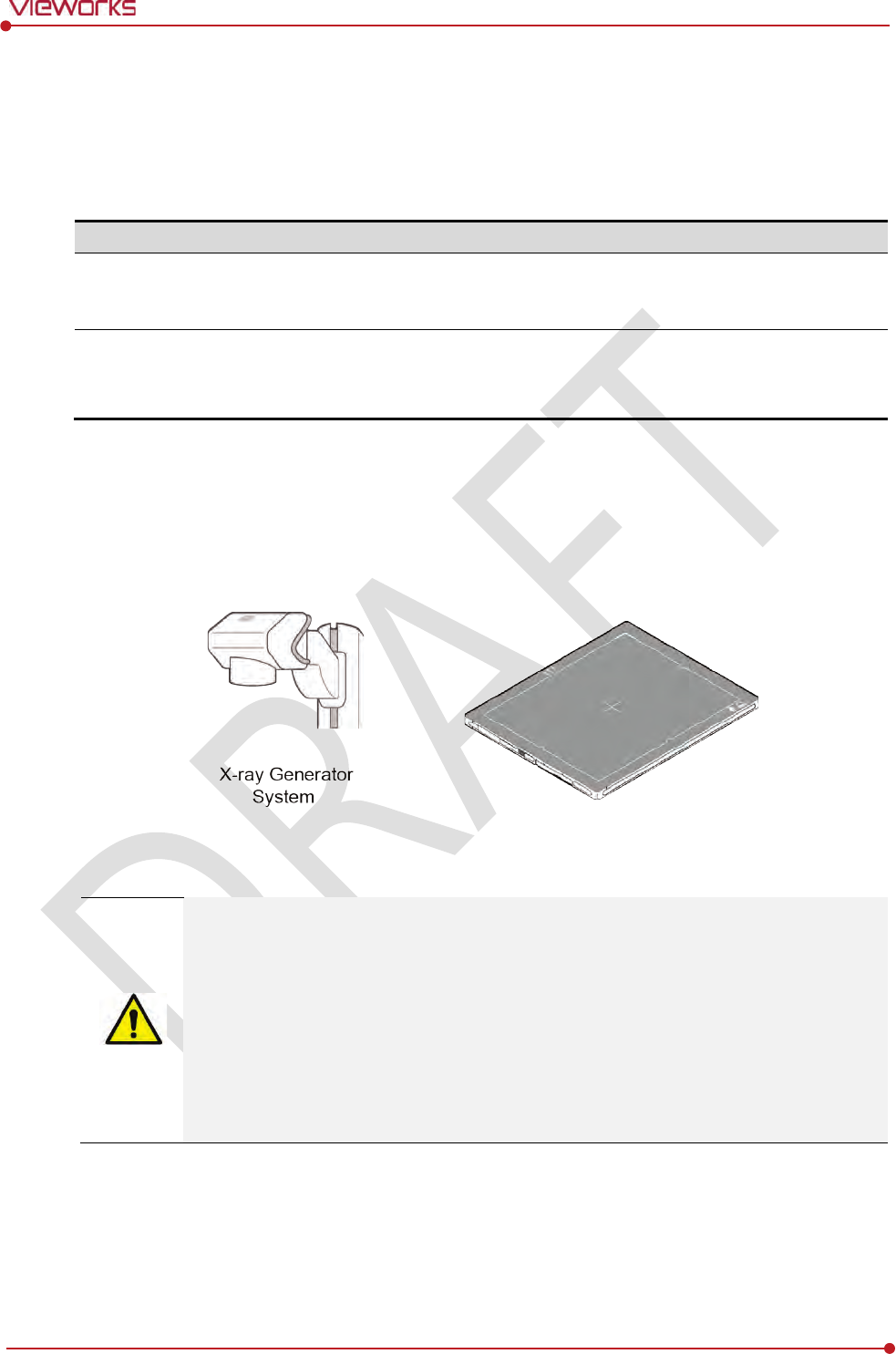
Rev.1.0
Page 55 of 151 VW40-152-009
VIVIX-S 1012N User Manual
3.4 Generator Interface
VIVIX-S 1012N detector provides DR Trigger interface and AED interface as a generator interface way to
acquire images by detecting X-ray.
Mode
Description
AED
The detector detects
X-ray exposure from the generator automatically and then performs
image
acquisition without any cable connection.
DR Trigger
T
he detector and generator receive and send their signal to each other for image
acquisition.
SCU and X-ray generator should be connected with the generator interface
cable.
3.4.1 AED (Auto Exposure Detection) Interface
If the VIVIX-S 1012N detector is used as the AED interface, you can acquire images without connecting the
generator to the detector with a generator interface cable.
Cautions when using AED interface
Make sure to follow the operating environmental condition (Temp: +10℃ ~ +35℃).
Do not give impact to the product. If it receives strong jolt, unwanted images may be
acquired without the X-ray exposure because of the malfunction of the AED sensor.
You may not acquire images or horizontal artifacts may occur depending on the external
environment such as exposure condition, thickness of object or the use of grid.
When you set X-ray exposure area to the direction of the detector, the center of the
detector should be involved in the X-ray exposure area. Otherwise, you may not acquire
an image.
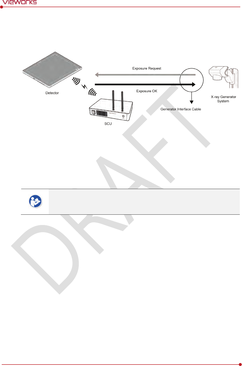
Rev.1.0
Page 56 of 151 VW40-152-009
VIVIX-S 1012N User Manual
3.4.2 DR Trigger Interface
Connect the detector and X-ray generator with a generator interface cable, and then acquire images by
sending and receiving their signal.
Signal Processing Steps
1 The detector receives EXP_REQ signal from the X-ray generator.
2 After the detector completes to prepare image acquisition, it sends the EXP_OK signal to the X-ray
generator.
3 The X-ray generator confirms EXP_OK signal and generates X-rays.
4 The detector acquires images and then transmits the image data.
EXP_REQ is a sending signal from X-ray generator to the detector for requesting
exposure.
EXP_OK is an exposure ready signal from the detector to X-ray generator.
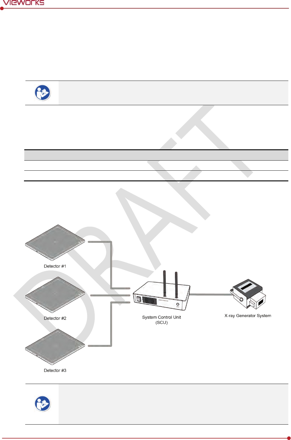
Rev.1.0
Page 57 of 151 VW40-152-009
VIVIX-S 1012N User Manual
3.5 Configuring DR Trigger Interface
To configure the DR Trigger interface, SCU and the generator should be connected with a generator
interface cable. Connect the one end of generator interface cable to EXT_INF port of SCU, and then
connect the other end to the generator.
Up to three generators can be connected with SCU Basic.
Only one generator can be connected with SCU mini.
3.5.1 Trigger Interface Way
The generator interface cable is connected differently depending on the two (2) types of trigger interface.
Trigger Interface
Description
Packet Trigger
H
andles exposure signal by exchanging packet.
Line Trigger
Handle
s exposure signal by exchanging electrical signal.
3.5.2 Packet Trigger
Multipe detectors share one generator signal together.
Connect a generator interface cable to one of the pin groups.
The generator tramsmits and receives signal with the one selected detector for taking
images.
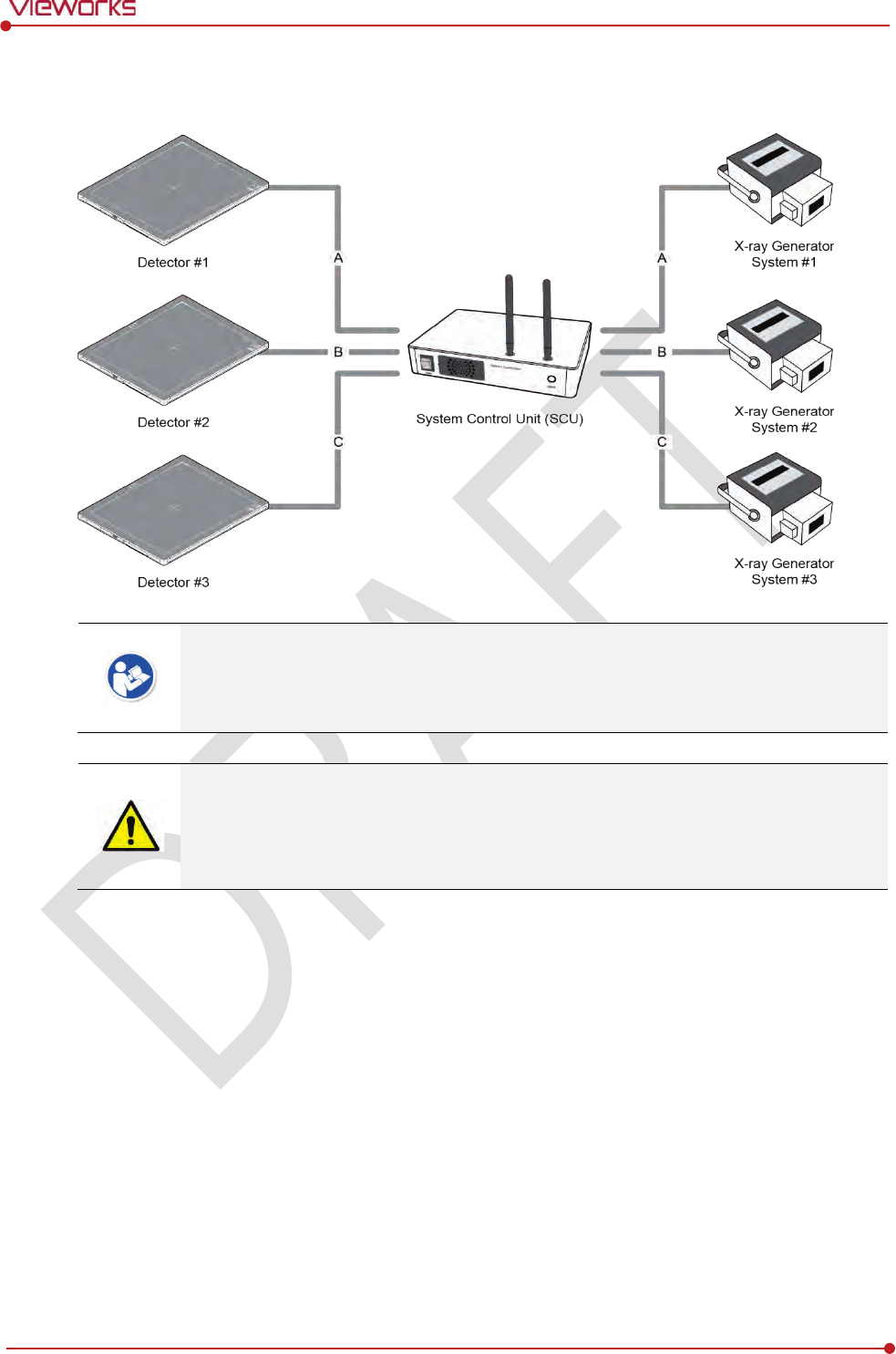
Rev.1.0
Page 58 of 151 VW40-152-009
VIVIX-S 1012N User Manual
3.5.3 Line Trigger
Each detector shares a signal signal by being connected with generators separately.
Up to three X-ray generators can be connected to SCU.
The connection of each detector and generator can be configured from VIVIX Setup.
You should comprehend about a detector and X-ray generator to make correct exposure.
Otherwise, X-ray can be exposed to the detector in different location.
The engineer who understand the generator device and interface technology should be in
charge of interface work between SCU and the generator.
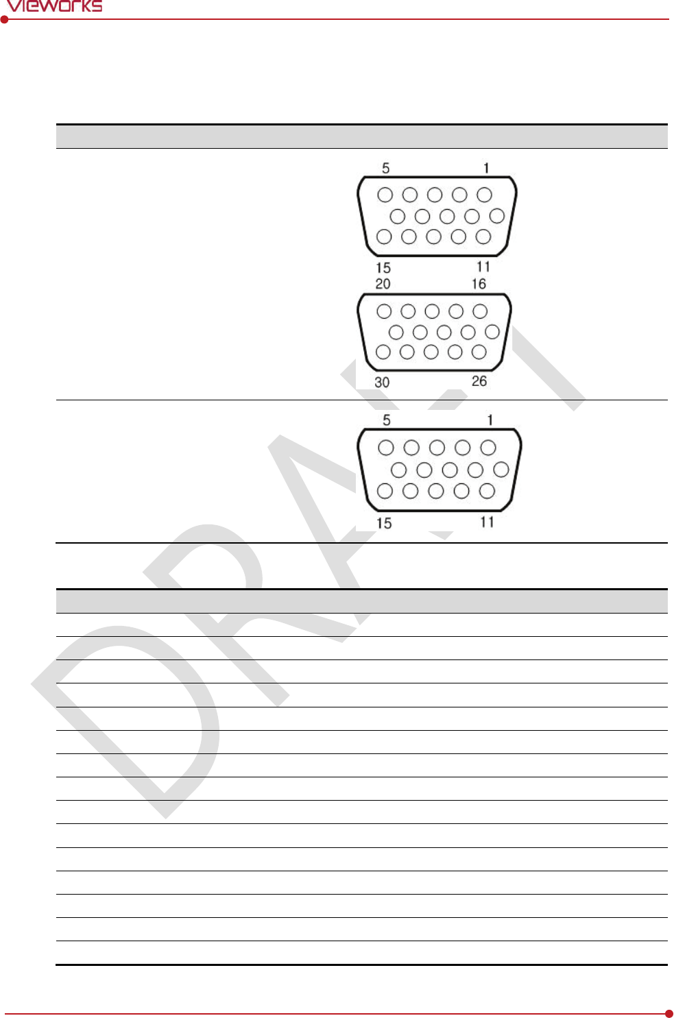
Rev.1.0
Page 59 of 151 VW40-152-009
VIVIX-S 1012N User Manual
3.5.4 EXT_INF Port Pin Map
EXT_INF port is D-SUB 15 pin female connectors of SCU, and used for the generator interface.
Product
EXT_INF port
SCU
Basic (FXRS-03A)
SCU
mini (FXRS-04A)
EXT_INF1 port pin map definition (1 ~ 15)
No.
Signal name
I/O
Type
Color
Ch.
Description
1
EXP_REQ+_A
Input
Contact
Red
A
Receive
s EXP_REQ
2
EXP_REQ
-_A
Input
Contact
Black
A
Return
s signal from EXP_REQ+_A
3
EXP_REQ_TTL_A
Input
TTL
Orange
A
Receive
s EXP_REQ
4
EXP_REQ_GND_A
Input
TTL
Gray
A
Return
s signal from EXP_REQ_TTL_A
5
EXP_OK_POWER_A/B
Input
-
Yellow
A/B
Power of TTL signal
6
EXP_OK+_A
Output
-
Green
A
S
ends EXP_OK
7
EXP_OK
-_A
Output
-
Brown
A
Return
s signal from EXP_OK+_A
8
EXP_OK+_B
Output
-
Blue
B
S
ends EXP_OK
9
EXP_OK
-_B
Output
-
Pink
B
Return
s signal from EXP_OK+_B
10
Reserved
-
-
-
-
Reserved for test only
.
11
EXP_REQ+_B
Input
Contact
White
B
Receive
s EXP_REQ
12
EXP_REQ
-_B
Input
Contact
Purple
B
Return
s signal from EXP_REQ+_B
13
EXP_REQ_TTL_B
Input
TTL
White
/Red
B
Receive
s EXP_REQ
14
EXP_REQ_GND_B
Input
TTL
White
/Black
B
Return
s signal from EXP_REQ_TTL_B
15
Reserved
-
-
-
-
Reserved for test only
.
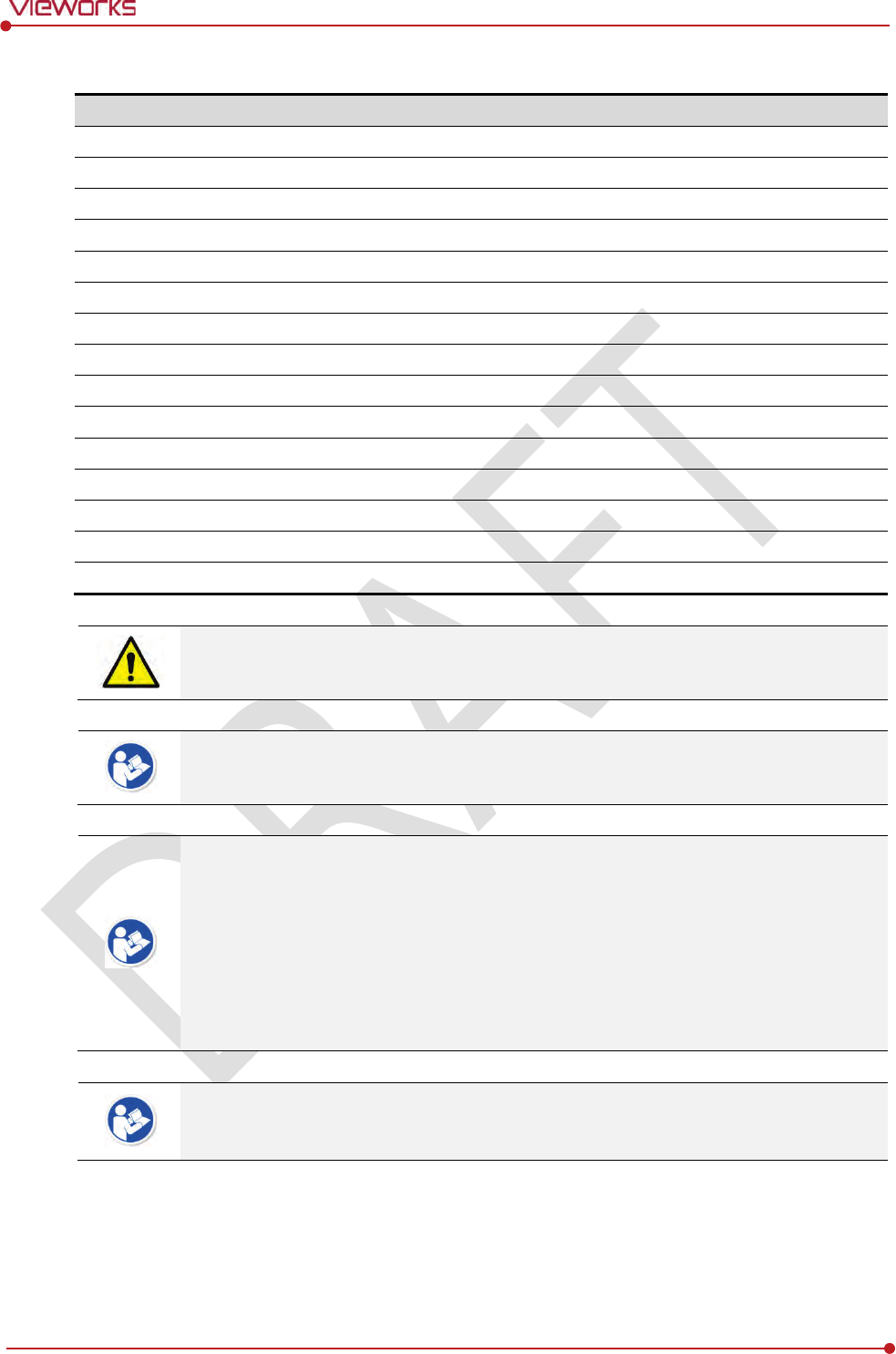
Rev.1.0
Page 60 of 151 VW40-152-009
VIVIX-S 1012N User Manual
EXT_INF2 port pin map definition (16 ~ 30)
No.
Signal name
I/O
Type
Color
Ch.
Description
16
EXP_REQ+_C
Input
Contact
Red
C
Receive
s EXP_REQ
17
EXP_REQ
-_C
Input
Contact
Black
C
Return
s signal from EXP_REQ+_C
18
EXP_REQ_TTL_C
Input
TTL
Orange
C
Receive
s EXP_REQ
19
EXP_REQ_GND_C
Input
TTL
Gray
C
Return
s signal from EXP_REQ_TTL_C
20
EXP_OK_POWER_C
Input
-
Yellow
C
Power of TTL signal
21
EXP_OK+_C
Output
-
Green
C
S
ends EXP_OK signal
22
EXP_OK
-_C
Output
-
Brown
C
Return
s signal from EXP_OK+_C
23
EXT_
W+
Input
Contact
-
-
User
-defined Pin 1
24
EXT_
W-
Input
Contact
-
-
Return
s signal from EXT_W+
25
EXT_
X+
Input
Contact
-
-
User
-defined Pin 2
26
EXT_
X-
Input
Contact
-
-
Return
s signal from EXT_X+
27
EXT_
Y+
Input
Contact
-
-
User
-defined Pin 3
28
EXT_
Y-
Input
Contact
-
-
Return
s signal from EXT_Y
29
EXT_
Z+
Input
Contact
-
-
User
-defined Pin 4
30
EXT_
Z-
Input
Contact
-
-
Return
s signal from EXT_Z+
Since SCU mini has EXT_INF 1 port, only one generator can be connected with.
Up to three X-ray generators can be connected to EXT_INF1 and EXT_INF2 ports, and
each generator should be connected with a same channel.
There are Contact type (OPEN/ CLOSE) and TTL type (ON/ OFF) on the signal in/output
pin.
TTL type information
ON : VCC
OFF : GND
Current: 5 ㎃ ~ 10 ㎃
Voltage: 12 V ~ 24 V
When you plan to add interface using a user-defined pin, contact to the person in charge
of Vieworks.
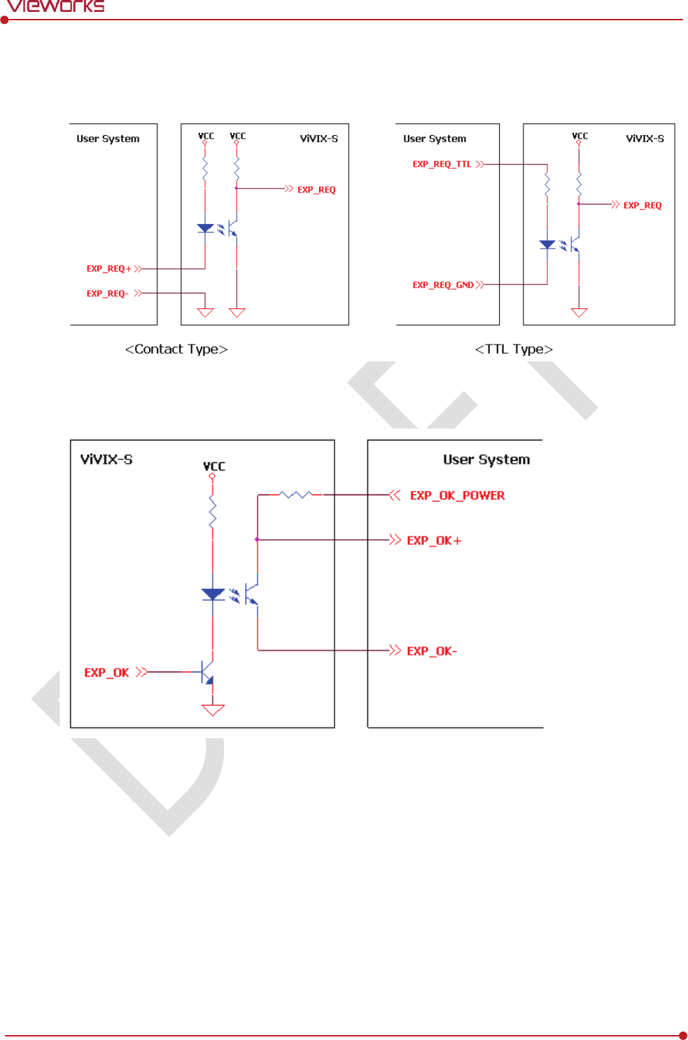
Rev.1.0
Page 61 of 151 VW40-152-009
VIVIX-S 1012N User Manual
3.5.5 Input / Output Circuit
Exposure Request Input Circuit (EXP_REQ)
Exposure Respond Output Circuit (EXP_OK)

Rev.1.0
Page 62 of 151 VW40-152-009
VIVIX-S 1012N User Manual
4. Installation
This section gives information about the installation process and method to use a detector.
Battery Pack
Product Installation
Generator Connection
Software Installation
Windows Environment Setting
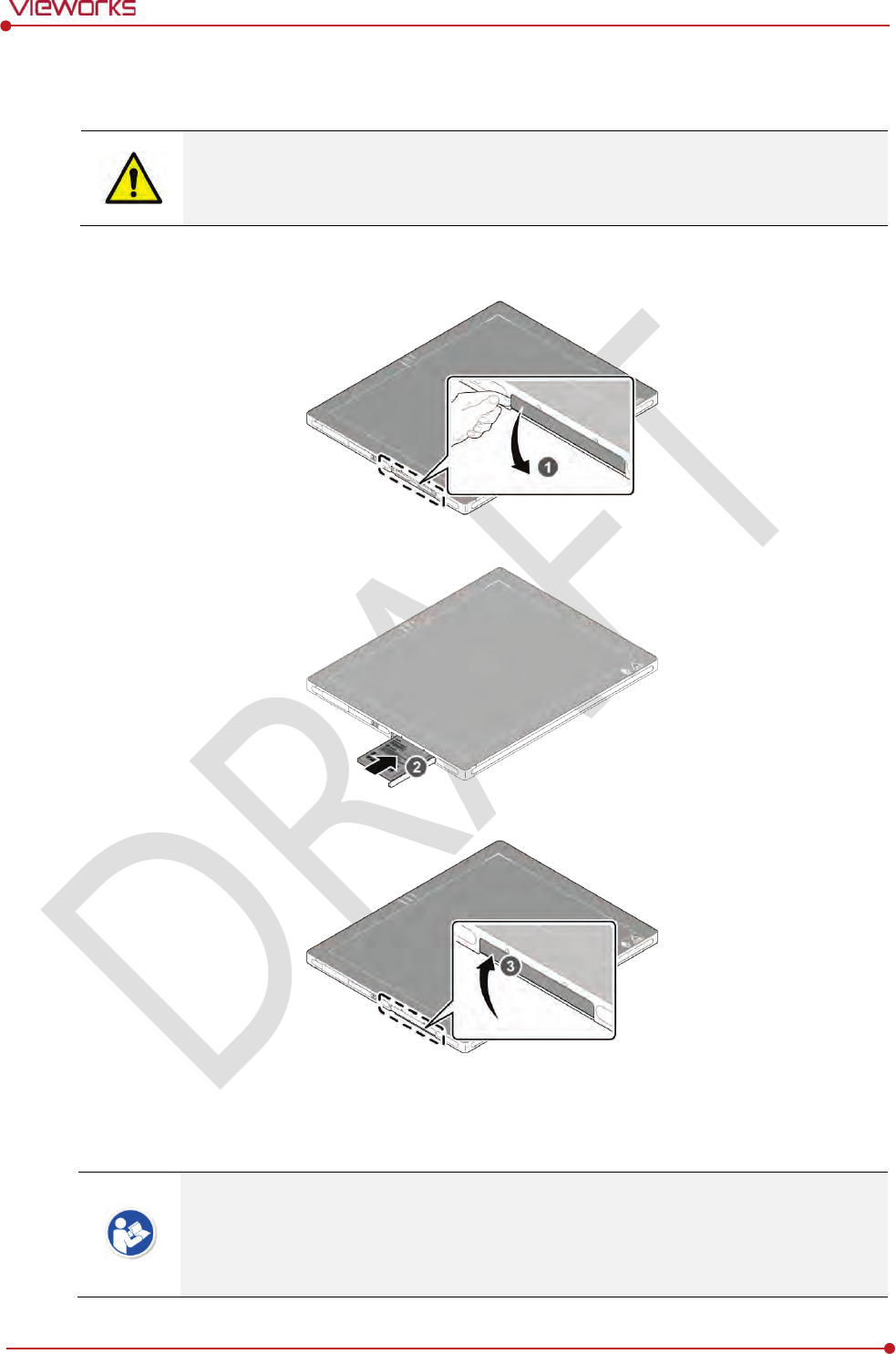
Rev.1.0
Page 63 of 151 VW40-152-009
VIVIX-S 1012N User Manual
4.1 Battery Pack
Detector and its attached devices should be installed by an authorized service engineer.
If you encounter any problems, consult the sales representative in Vieworks or a relevant
engineer.
4.1.1 How to insert a battery pack
1 Open the battery cover.
2 Insert a battery into a slot until it clicks and push the lever to the right for fixing the battery.
3 Close the battery cover.
Check if the battery is fully charged before using.
Make sure that the battery pack is securely inserted.
The remaining battery can be checked from the battery lamp on the side of detector or
from the VIVIX Setup program.
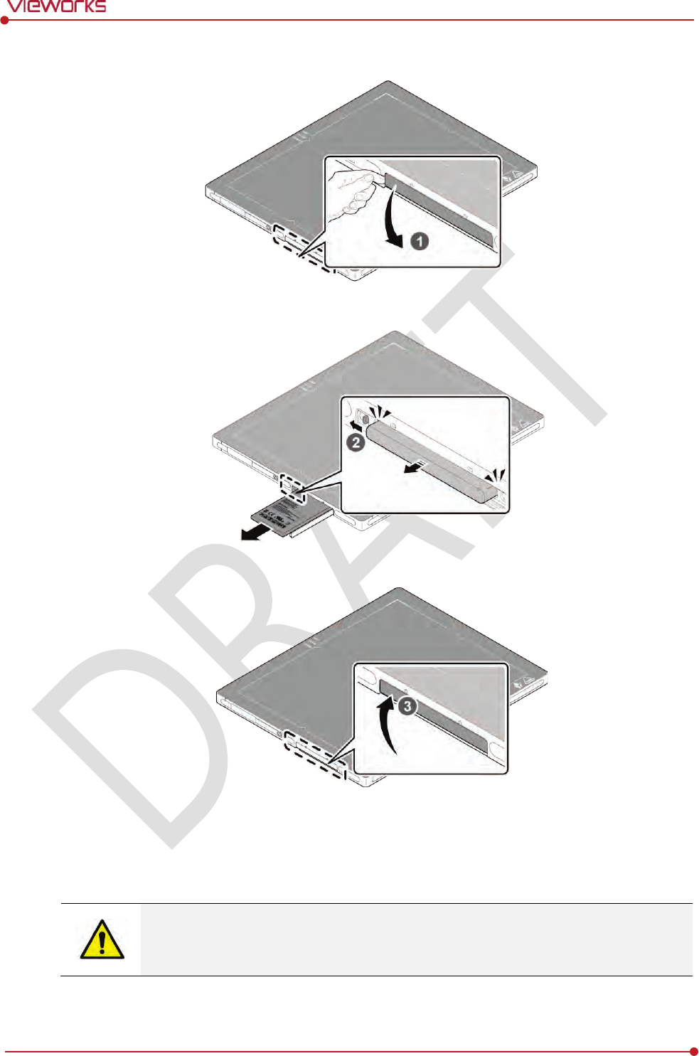
Rev.1.0
Page 64 of 151 VW40-152-009
VIVIX-S 1012N User Manual
4.1.2 How to take out a battery pack
1 Open the battery cover.
2 Push the lever to the left for taking out the battery.
3 Close the battery cover.
Make sure to turn off the detector by pressing and hold the power button for 3 seconds
before detaching a battery pack. All status LED lamps are off and then the detector is
turned off.
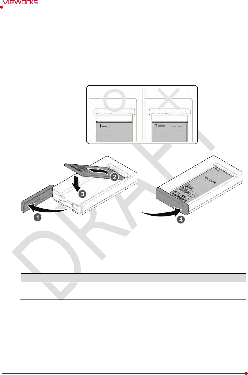
Rev.1.0
Page 65 of 151 VW40-152-009
VIVIX-S 1012N User Manual
4.1.3 How to charge a battery pack
The detector is battery-operated when it is connected wirelessly. Charge the battery pack fully before
inserting it to the detector.
Charging type 1
Supply power to the charger with the power adapter before charging a battery. When the power LED is
turned to green, it means that the power is permitted.
1 Open the cover at the lower side of charger.
2 Put the battery on the top of charger in the right direction.
3 Push the battery down until it is fixed in the charging part.
4 Close the cover at the lower side of charger.
Stimultaneous charging
Charging time
Battery
charger
2
battery packs
3
hrs
Tether interface cable
1
battery pack
4
hrs
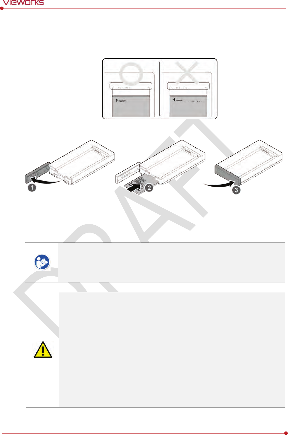
Rev.1.0
Page 66 of 151 VW40-152-009
VIVIX-S 1012N User Manual
Charging type 2
Supply power to the charger with the power adapter before charging a battery. When the power LED is
turned to green, it means that the power is permitted.
1 Open the cover at the lower side of charger.
2 Insert the battery into the slot until it clicks.
3 Close the cover at the lower side of charger.
The charging time can be different depending on temperature and charging status of a
battery.
While charging a battery pack, it is available to use the detector by connecting it with a
tether interface cable.
This detector is designed to make a battery being discharged little by little during the
detector is off. Therefore, remove the battery pack when the detector is not used for
some time. Otherwise, over discharge may occur resulting in the shortened battery life.
Do not use the charger around the paitent.
Charge the battery with the charger provided by Vieworks.
Securely plug the power cord of the charger into the AC outlet. If contact failure occurs,
or if dust/metal objects come into contact with the exposed metal prongs of the plug, fire
or electric shock may result.
Stop charging the battery when status LED of the charger turns to green
as exceeding the
specified charging time. Otherwise, the battery pack is overcharged and it causes smoke.
If the battery pack is overheating, it can be exploded and a fire may occur.
Use only a power adapter complying with IEC 60601-1 or IEC 60950-1.
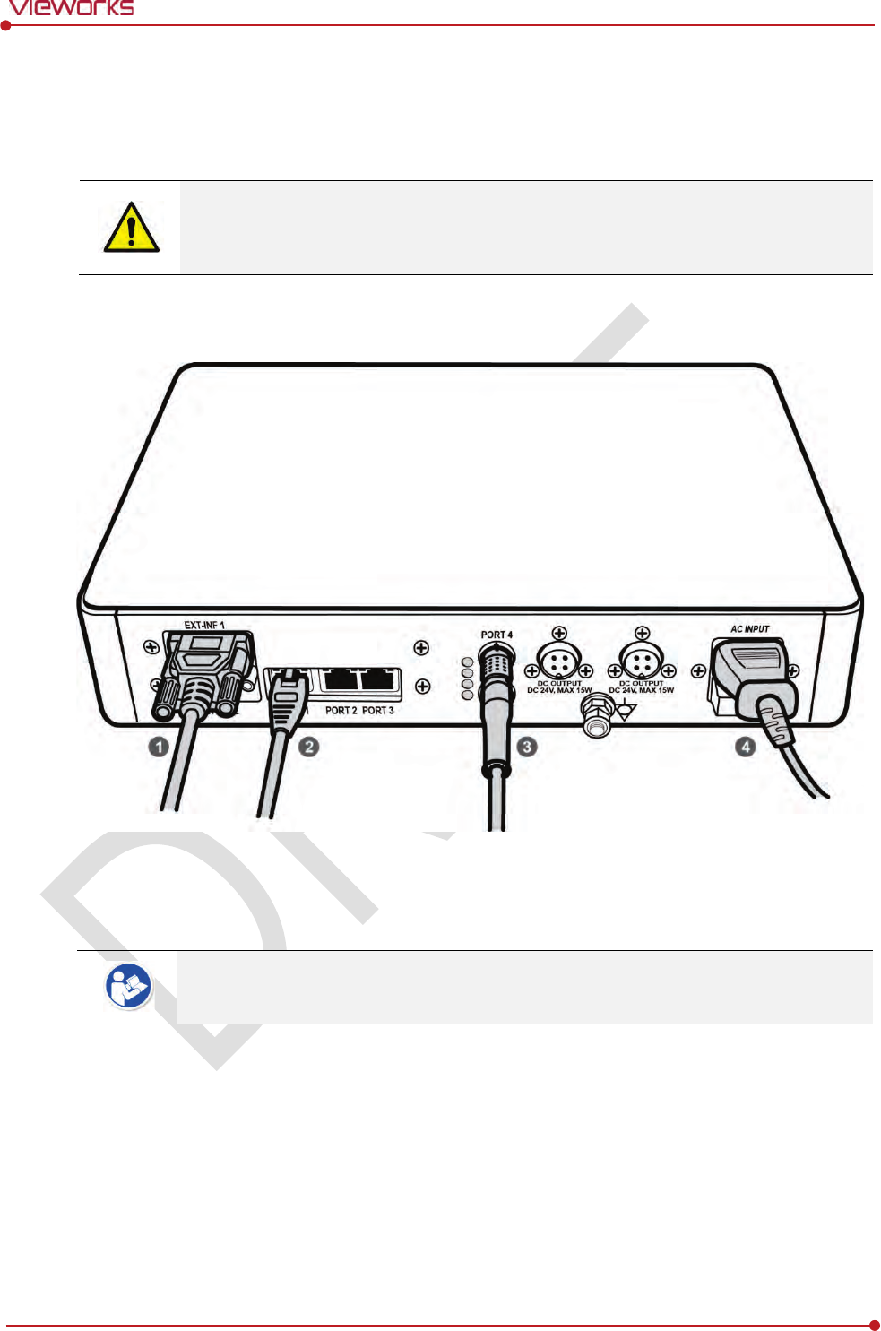
Rev.1.0
Page 67 of 151 VW40-152-009
VIVIX-S 1012N User Manual
4.2 Product Installation
4.2.1 Connecting Devices
Installation of this equipment should be made by licensed and authorized personnel by
Vieworks.
This equipment must only be connected to the power with protective earth.
SCU Basic (FXRS-02A)
1 If you use the DR Trigger mode, connect the one end of generator interface cable to the EXT_INF port
of SCU, and the other to the X-ray generator.
If you use the AED mode, a generator interface cable is not needed as the detector
operates by detecting X-ray automatically.
2 Connect one end of the LAN cable to one of the LAN ports of SCU, and the other to the LAN Card
Connector of workstation assigned for data transfer.
3 Connect the one end of the Tether Interface cable to the Port 4 or Port 5 of SCU and the other to the
detector.
4 To supply power, connect the AC power cable to the AC power input port of SCU.
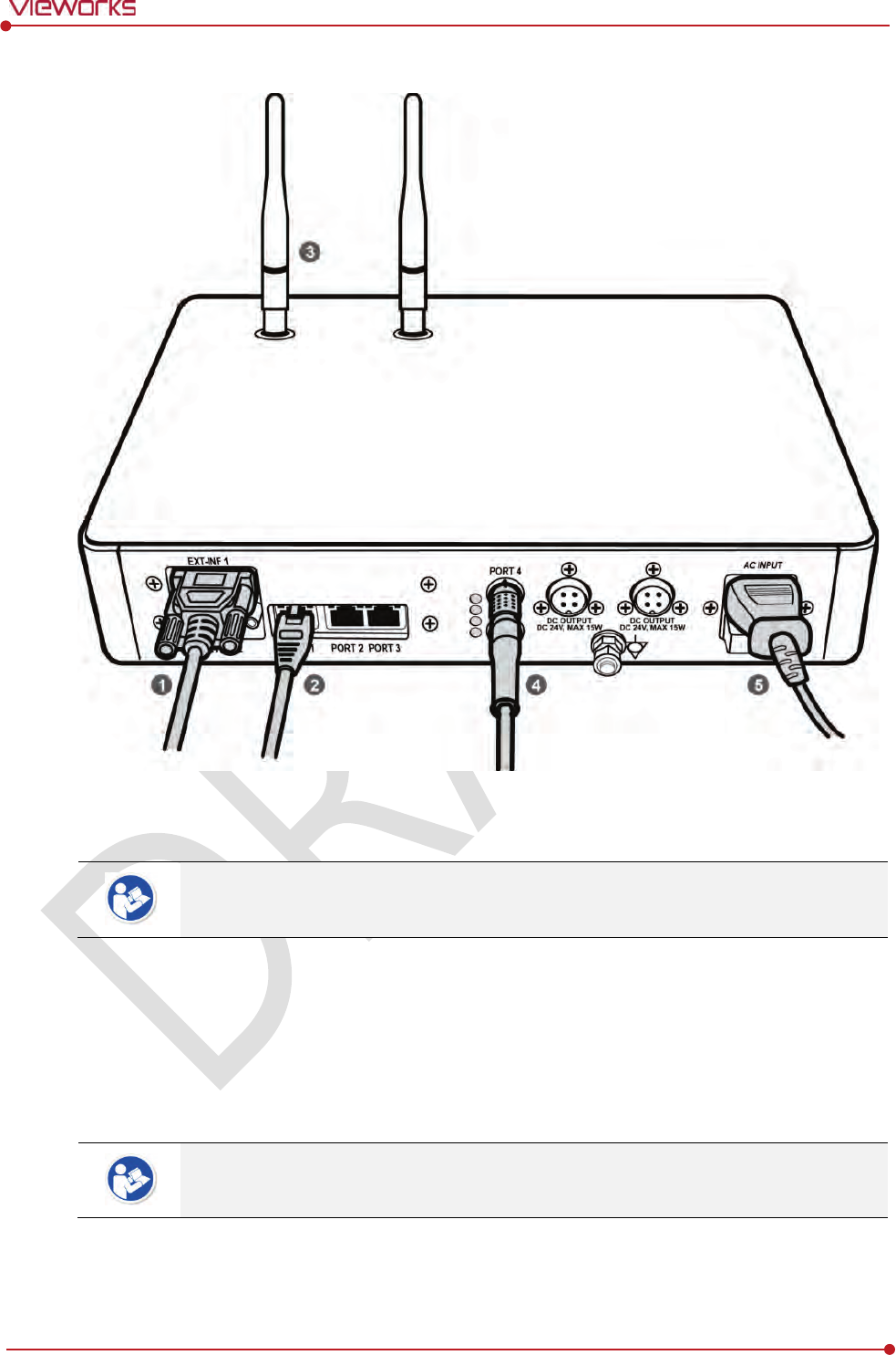
Rev.1.0
Page 68 of 151 VW40-152-009
VIVIX-S 1012N User Manual
SCU Basic (FXRS-03A)
1 If you use the DR Trigger mode, connect the one end of generator interface cable to the EXT_INF port
of SCU, and the other to the X-ray generator.
If you use the AED mode, a generator interface cable is not needed as the detector
operates by detecting X-ray automatically.
2 Connect one end of the LAN cable to one of the LAN ports of SCU, and the other to the LAN Card
Connector of workstation assigned for data transfer.
3 Stand the antenna of SCU upright.
4 To transmit image data using a Tether Interface, connect the one end of the Tether Interface cable to
the Port 4 or Port 5 of SCU and the other to the detector.
If you use the wireless communication method, a tether interface cable is not needed as
the image is transmitted wirelessly.
5 To supply power, connect the AC power cable to the AC power input port of SCU.
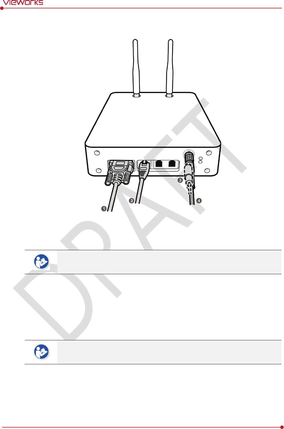
Rev.1.0
Page 69 of 151 VW40-152-009
VIVIX-S 1012N User Manual
VIVIX SCU mini (FXRS-04A)
1 If you use the DR Trigger mode, connect the one end of generator interface cable to the EXT_INF port
of SCU mini, and the other to the X-ray generator.
If you use the AED mode, a generator interface cable is not needed as the detector
operates by detecting X-ray automatically.
1 Connect one end of the LAN cable to one of the LAN ports of SCU mini, and the other to the LAN
Card Connector of workstation assigned for data transfer. Stand the antenna of SCU mini upright.
2 To transmit image data using a tether interface, connect the one end of the tether interface cable to
the port of VIVIX SCU mini and the other to the detector.
If you use the wireless communication method, a tether interface cable is not needed as
the image is transmitted wirelessly.
3 To supply power, connect the DC power cable to the DC power input port of SCU mini.
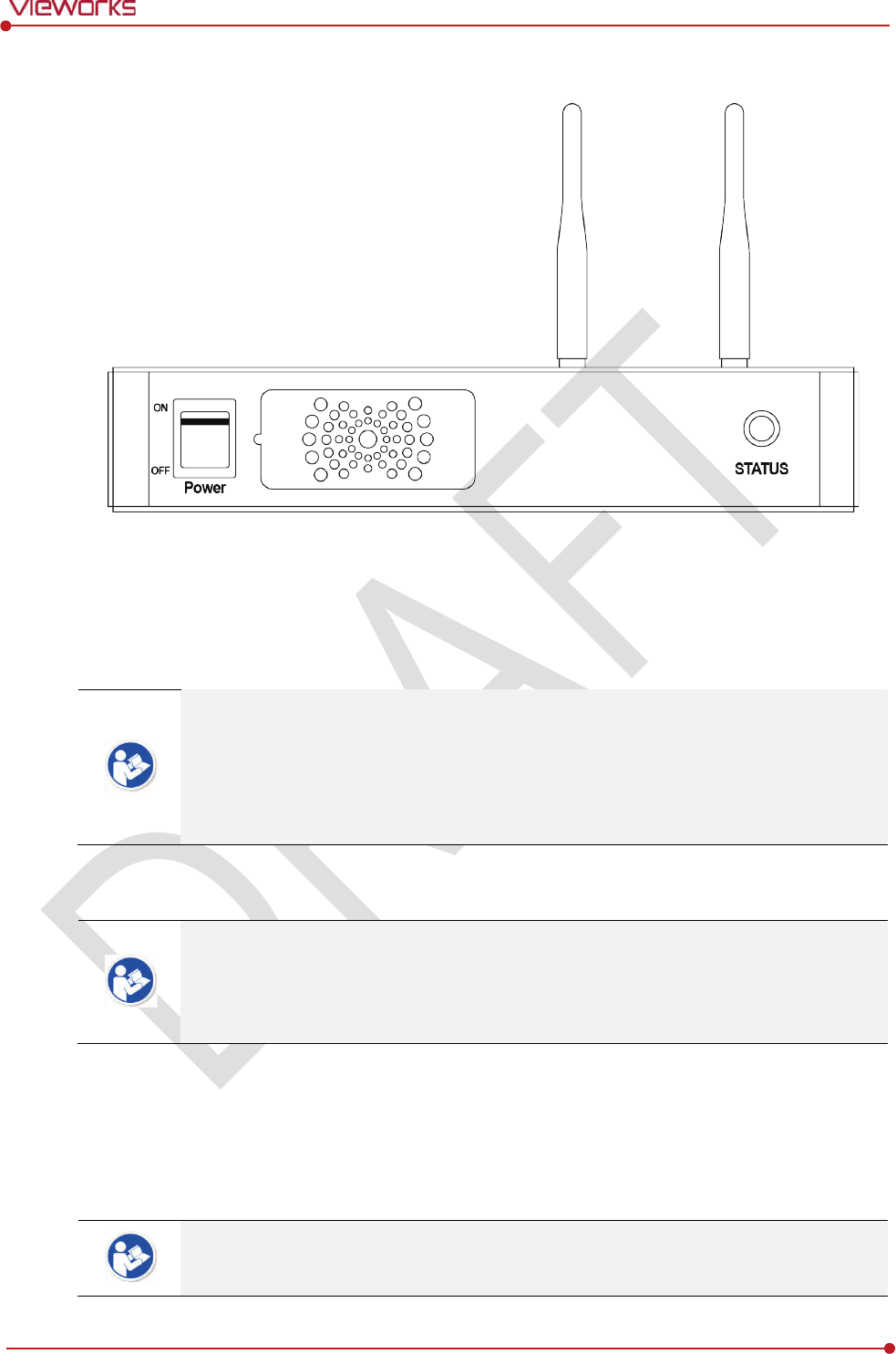
Rev.1.0
Page 70 of 151 VW40-152-009
VIVIX-S 1012N User Manual
4.2.2 Booting up SCU
1 Turn on the power switch at the front side of SCU.
2 Check if the power switch of SCU lights up green.
3 Check if the status indicator is blinking in green after the power switch of SCU is permitted.
4 Check if the status indicator of SCU is blinking in green and turns to light up in the same color.
When the power switch lights up green, it means that the power is applied normally.
When the status indicator is blinking in green, the SCU is booting.
If the status indicator lights up green, it indicates that the SCU is being operated normally
after booting up.
If the status indicator lights up blue, SCU’s preparation for communication is completed.
4.2.3 Booting up the Detector
The procedures in this chapter are explained according to the default setting status of a
detector (factory reset) and the use of wireless connection.
Refer to <7.4 Product Initialization> for the detailed information about the default setting
status of a detector.
1 Attach a charged battery pack to the detector.
2 Press the power button of the detector for 1 second until the power LED is turned on.
3 When the power LED is on, check if it is lit green.
4 Check if the active LED is lit orange on the detector.
If the power LED lights up green, the DC power is permitted normally.
If the active LED lights up orange, the detector is compeleted to boot up normally.

Rev.1.0
Page 71 of 151 VW40-152-009
VIVIX-S 1012N User Manual
4.2.4 Checking Status LED of Detector
Power LED
The power LED indicates the power status information which is permitted to the detector in green.
The power LED lights up when the power is permitted normally.
If the detector is connected with a tether interface, the power LED lights up when power is permitted
to SCU because the detector is supplied power from SCU.
Active LED
The active LED indicates status information about the possibility that the detector can be used
normally or not in orange.
The active LED is blinking when the detector is completed to boot up normally.
The Power LED is blinking when the detector turns to sleep mode.
The active LED is blinking when the wireless communication is being initialized.
Data LED
The data LED indicates status information of data processing in blue.
The data LED lights up when the detector is available to make data communication.
The data LED is blinking while the detector transmits or saves data.
If the detector AP is on, the LED blinks for 5 times right after the booting.
Detector AP LED
The AP LED lights up in blue when the detector AP is on.
The AP LED is blinking in blue when the detector switches the AP status.
The AP LED is blinking in orange while the detector is synchronizing the wireless settings.
The communication status of detector is indicated when the detector AP is off.
Wirelss communication: Green LED at the 3rd level or higher / Orange LED under 2nd level.
Wired communication: Green LED in case of 1Gbps / Orange LED in case of 100Mbps connection.
Summary List of Detector Status LED
Information
Power
LED Status LED
Data
LED
In process of booting after the power
permission
Blink OFF
OFF
Booting completed
(Abnormal) ON -
-
Booting completed
(Normal) ON ON
OFF
Ready for communication
ON ON ON
Sleep Mode
ON Blink
OFF
In process of wireless
initialization ON Blink
OFF
Data Communication
(Send or Store) ON ON Blink
Power
OFF
OFF
OFF
OFF
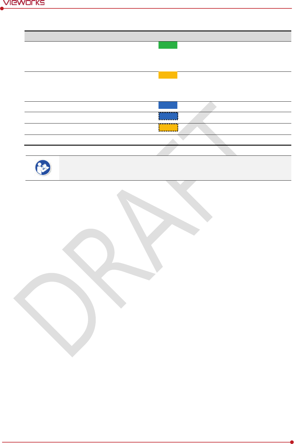
Rev.1.0
Page 72 of 151 VW40-152-009
VIVIX-S 1012N User Manual
Summary list of the Detector AP LED
Information
Detector
AP LED
Detector
AP OFF (Communication status: Good)
Wireelss communication: 3rd level or higher
Wired communication: 1000Mbps
ON
Detector
AP OFF (Communication status: Normal)
Wireelss communication: Under 2nd level
Wired communication: 100Mbps
ON
Detector
AP ON ON
Switching the status of detector
AP Blink
The wireless setting is being synchronized
Blink
Power
OFF
OFF
If the LED blinks abnormally, refer to <8 Troubleshooting> to check if communication or
system error is occurred.
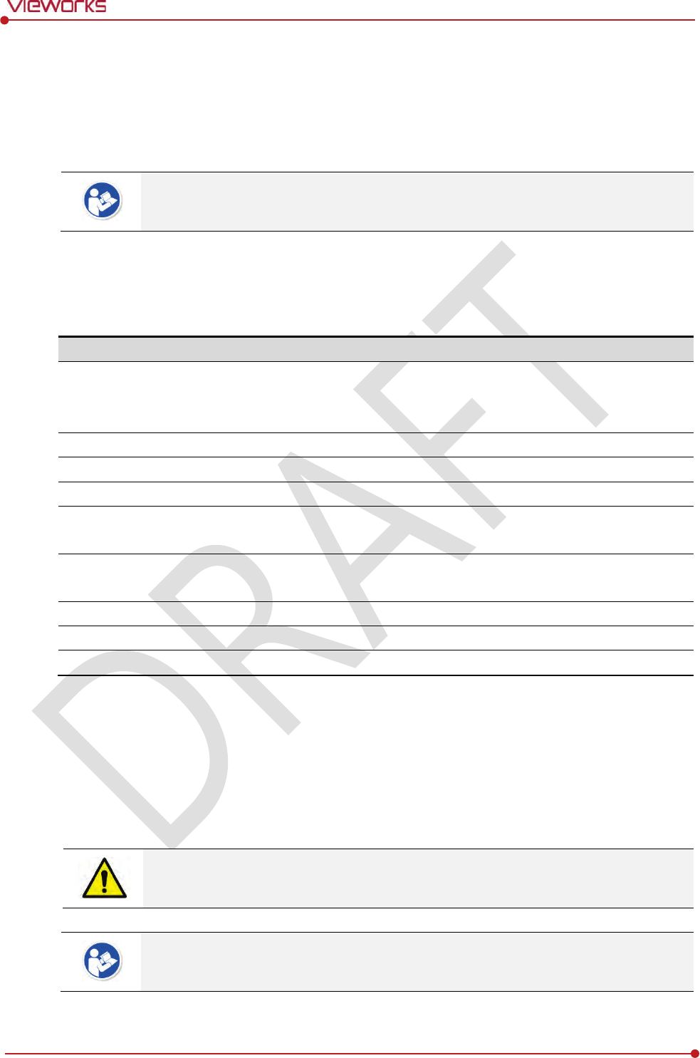
Rev.1.0
Page 73 of 151 VW40-152-009
VIVIX-S 1012N User Manual
4.3 Software Installation
This section gives information about how to install the software on the workstation (PC) and how to
configure the environment for software operation and communication.
Check suitability of acquiring, processing and adjusting of images by referring to the
recommended workstation specifications before the software installation.
4.3.1 Software Classification
Vieworks provides clients who purchase our detector system with software as below. You can choose and
use one of our softwares below.
Software
Description
VXvue
A program for acquiring and adjusting images developed by Vieworks.
Used for ViVIX-S detectors only.
Unnecessary to develop a separate viewer program.
VIVIX Setup
A program for setting and managing the detector and SCU.
VXvue (Viewer)
Software for acquiring, adjusting and managing the image.
XIPL
Image processing program
Document
VXvue Operation Manual
XIPL User Manual
VIVIX
SDK
Software development kit for ViVIX-S detector only, provided by Vieworks.
You can develop your own software dedicated to ViVIX-S by using this kit.
SDK Package
Development package
VIVIX Setup
A program for acquiring, adjusting and managing the image.
Document
VIVIX SDK Developer Manual
4.3.2 Software Installation
For a client who uses VXvue, install the VXvue program after reading VXvue Operation Manual
carefully.
For a client who uses VIVIX SDK, install the Setup program after reading VIVIX SDK Developer
Manual.
Be sure to install the software first with reading this manual before configuring Windows
environment.
Apart from the detector and SCU, the software can be installed separately.
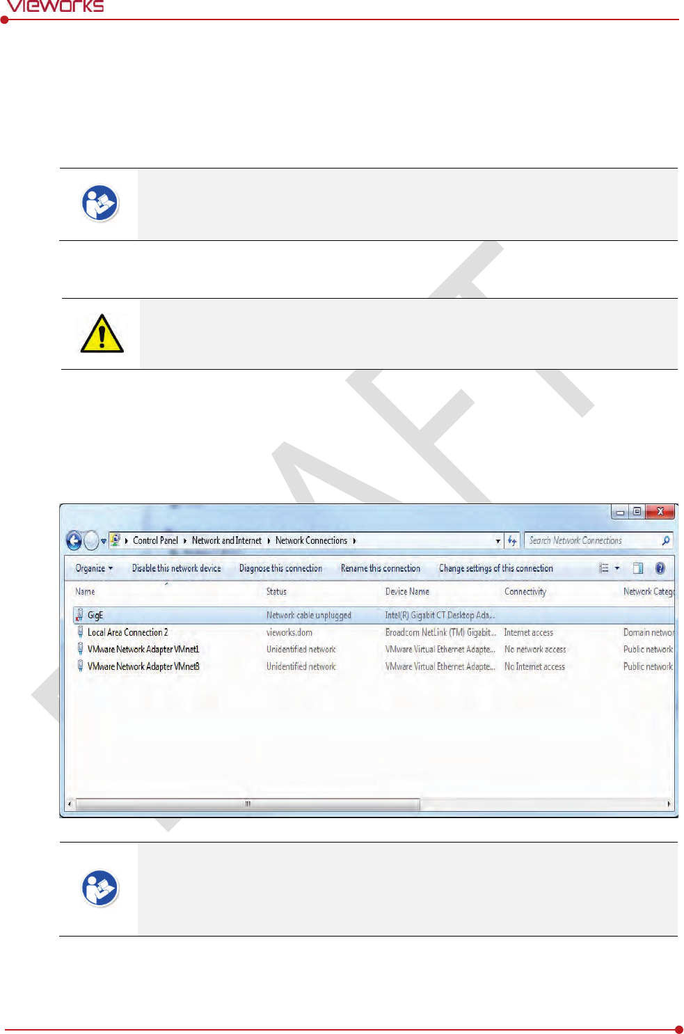
Rev.1.0
Page 74 of 151 VW40-152-009
VIVIX-S 1012N User Manual
4.4 Windows Environment Setting
This section gives information about configuring Windows to communicate with the detector and SCU after
installing the Setup program or Viewer.
The contents in this chapter are made on the basis of Windows 7.
Configuration environment can be different depending on network adaptor manufacturer
or models.
4.4.1 Network Configuration
Communication disruption between the detector (Or SCU) and workstation occurs unless
the network adaptor is proper is set properly, it may cause serious repercussion to the
product and image quality.
Selecting Network Adaptor
1 Click Start Control Panel Network and Internet Network and Sharing Center Change
Adapter Setting.
2 Choose the networks adaptor for communicating with the detector and SCU, and then rename it.
It is recommended to change the name of network adaptor to distinguish it from other
connection names.
Even though the name is changed, it will not affect to the operation and communication
performance of the equipment.
3 Click the chosen network adaptor with the right mouse button and click Properties to display the
Properties window.
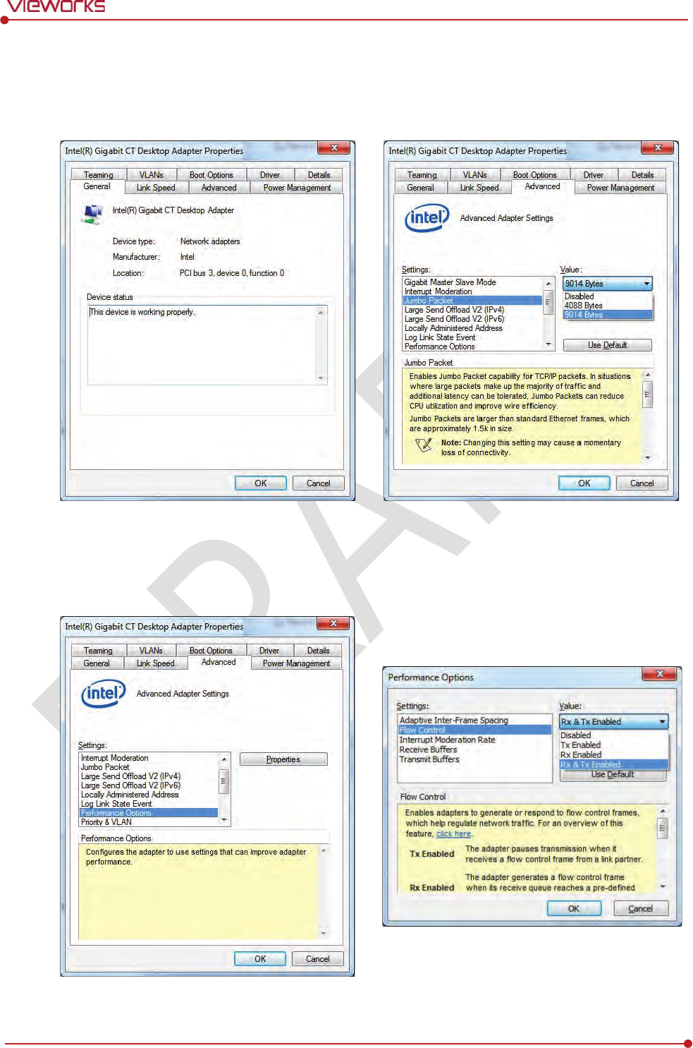
Rev.1.0
Page 75 of 151 VW40-152-009
VIVIX-S 1012N User Manual
Setting Network Adaptor
1 Click Configure button to open the following dialog box, and then go to the Advanced tab.
2 Set Jumbo Packet to the maximum value. (Recommended value: 9014 Bytes)
3 Choose Performance Options in the list of Settings and click Properties button on the right.
4 Choose Flow Control in the list of Settings and select Rx & Tx Enabled on the Value list as shown
below.
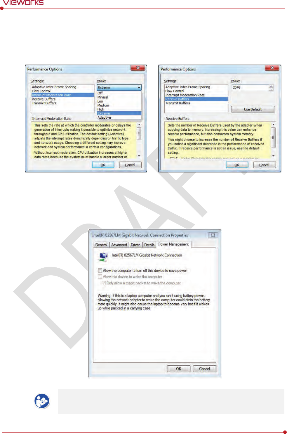
Rev.1.0
Page 76 of 151 VW40-152-009
VIVIX-S 1012N User Manual
5 Choose Interrupt Moderation Rate in the list of Settings and select Extreme on the Value list as
shown below.
6 Choose Receive Buffers and set it to the maximum value.
7 Click OK button.
Deactivate Power-Saving Mode on Network Adaptor
1 Click the Power Management tab and uncheck Allow the computer to turn off this device to save
power.
2 Click OK button.
Viewer may not work normally if the power save mode is activated.
Deactivate the power save mode of all the installed network adaptors.
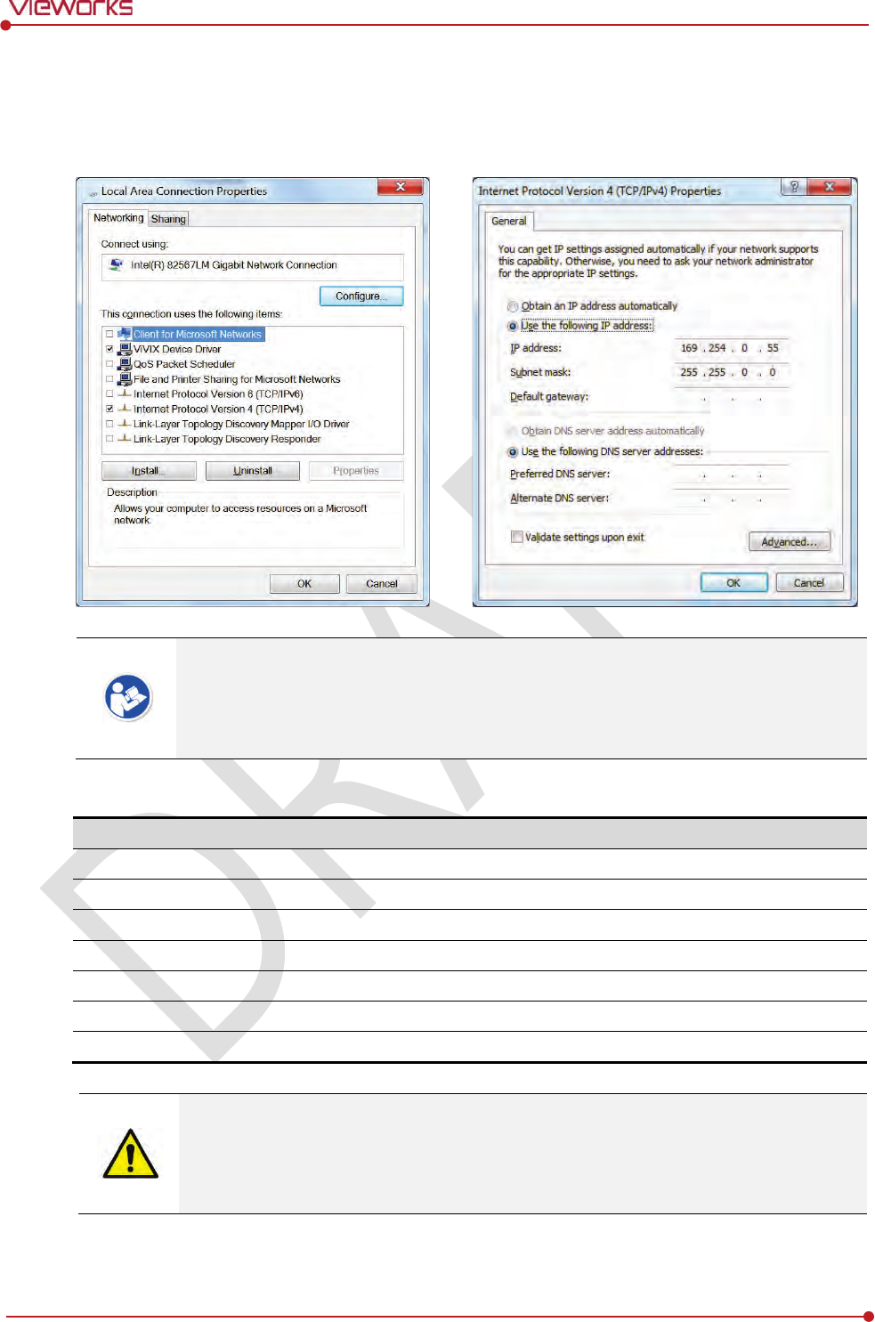
Rev.1.0
Page 77 of 151 VW40-152-009
VIVIX-S 1012N User Manual
Protocol Selection and IP Address Setting
1 Choose Internet Protocol Version 4 (TCP/IPv4).and click Properties button.
2 Input the IP address and subnet mask as shown below, and then click OK button.
ViVIX Device Driver is the image filter driver for acquiring images from a detector.
It is recommended to uncheck the other items on the list except for ViVIX Device Driver
and Internet Protocol Version 4(TCP/IPv4), since they are not related with the detector
communication.
Summary of Network Configuration
Item
Value
Jumbo Packet
Maximum or 9014 Bytes
Flow Control
Rx & Tx Enabled
Interrupt Moderation Rate
Extreme
Receive Buffers
Maximum
Allow the computer to turn off this device to save power
Unchecked
IP Address
169.254.0.(50 ~ 254)
Subnet Mask
255.255.0.0
It is recommended to set the IP address and subnet mask within the range presented in
this document.
If you use IP address and subnet mask out of the suggested range, it could be difficult to
identify and resolve the cause of communication disorder.
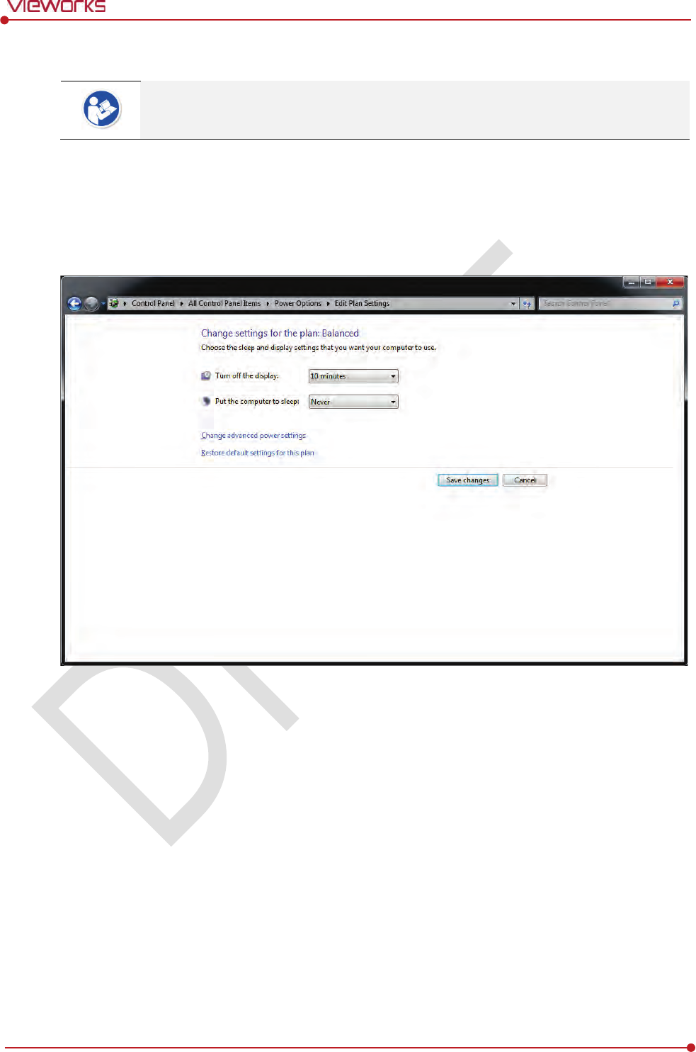
Rev.1.0
Page 78 of 151 VW40-152-009
VIVIX-S 1012N User Manual
4.4.2 Disabling Sleep Mode of Monitor
If you use the sleep mode, viewer may not work normally.
1 Click Start Control Panel Power Options and then move to the Choose when to turn off the
display tab.
2 Set Put the computer to sleep to Never to disable the sleep mode.
3 Click Save changes button.

Rev.1.0
Page 79 of 151 VW40-152-009
VIVIX-S 1012N User Manual
5. Setting
This section gives information about the product setting with using the Setup program.
Start Setting
SCU Setting
Detector Setting
Changing the Wireless Setting
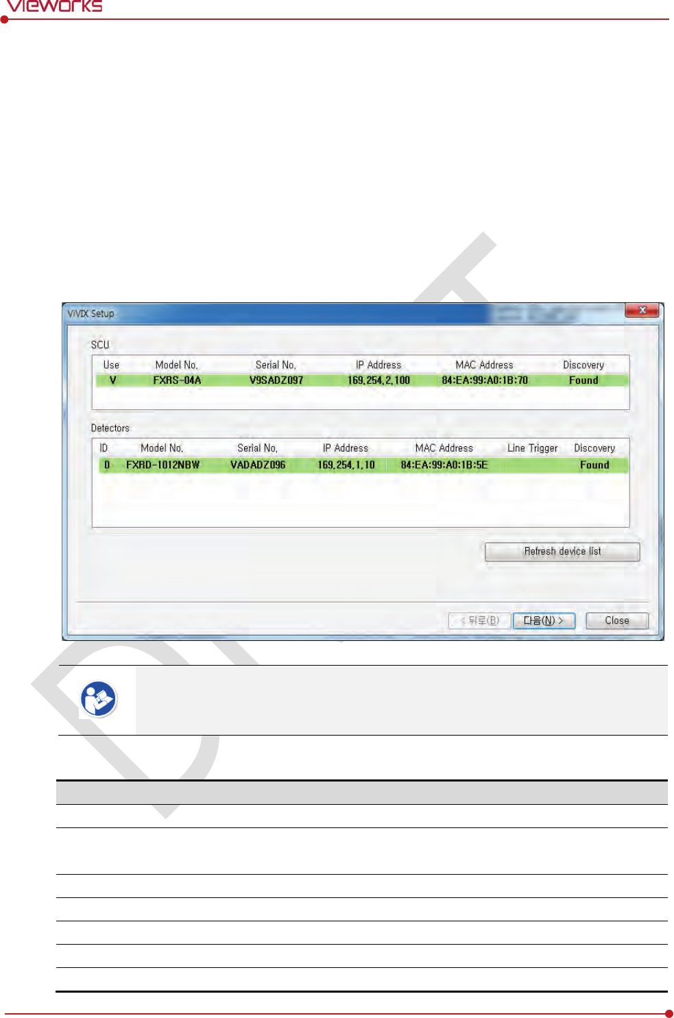
Rev.1.0
Page 80 of 151 VW40-152-009
VIVIX-S 1012N User Manual
5.1 Start Setting
5.1.1 Setup Program
The VIVIX Setup program provides functions for setting and managing the internal data to make VIVIX-S
1012N wireless detector and SCU work normally. In addition, The VIVIX Setup program has diagnostic
function for checking performance and abnormality of the devices as well as the image calibration function
for improving the image quality.
5.1.2 Checking Devices
Check information of the detector and SCU displayed on the Discovery list.
Click Refresh Device List button to make the VIVIX Setup program search all detectors
and SCU connected with the same network again. If devices are not displayed, check the
power connection of the detector and click Refresh Device List button again.
List Information
List
Description
SCU
Displays discovered list of SCU devices.
Use
Double
-click the option to decide wether to use SCU or not.
‘
V’ is displayed when it is able to be used.
Discovery
Displays whether SCU is found out or not.
Detectors
Displays discovered list of detectors. (Max. 4)
ID
ID of detector(sequence to distinguish registered detector)
Line Trigger
Selects a pin group when
using Line Trigger.
Discovery
Displays whether the detector is discovered or not.
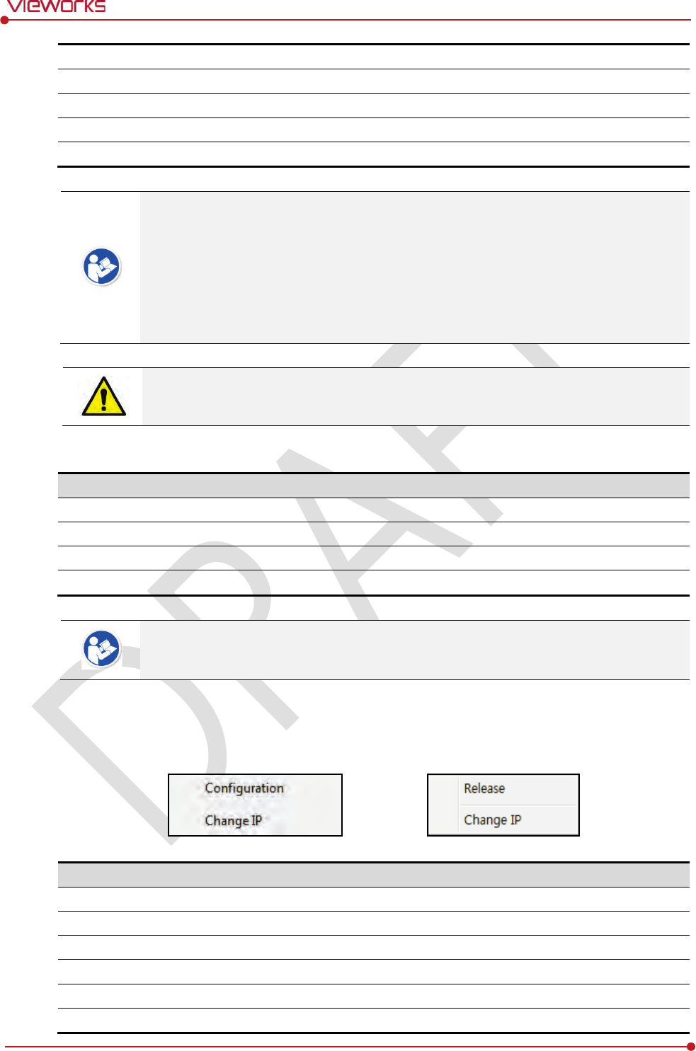
Rev.1.0
Page 81 of 151 VW40-152-009
VIVIX-S 1012N User Manual
Common
Model No.
Model name of SCU or detector
Serial No.
Serial number of SCU or detector
IP Address
IP Address of SCU or detector
MAC Address
MAC Address of SCU or
detector
The default IP address of SCU is 169.254.2.100.
The default IP address of detector is 169.254.1.10.
You can change the IP Address of detector or SCU. Refer to Change Configuration on
the next page.
MAC address is a unique indentifier of the network device. Do not change it randomly.
To change order of registered detectors’ ID, select an item and click ↑/↓buttons.
If detectors which have same IP address are connected at the same time, the address is
changed automatically to prevent address collision.
Color and Font
Information
Description
Green background
R
egistered status. Available to get into the device.
W
hite background
Non
-registred status. Unavailable to get into the device.
Bold font
C
onnected status. The device is connected.
Gray background / font
Disconnected status. The device h
as been connected, but is disconnected now.
The device is changed to the registered or non-registered status by double-clicking the
device name or clicking Select or Release button.
Change Configuration
Select the SCU or detector name and click the right mouse button to change its setting.
Menu
Description
SCU
-
Configuration
C
hanges the setting information of SCU.
Change IP
Changes IP address of SCU.
Detector
-
Release
Releases the detector to
non-registered status.
Change IP
C
hanges IP address of the detector.
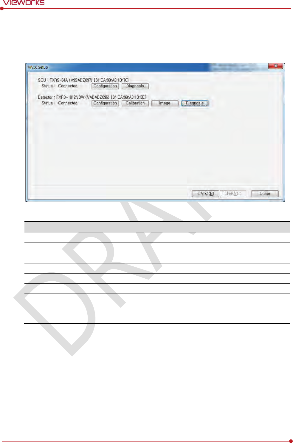
Rev.1.0
Page 82 of 151 VW40-152-009
VIVIX-S 1012N User Manual
5.1.3 Getting into the Devices
Click Next button to enter the registered SCU and detector. You can use SCU and the detector normally
when the Status of SCU is Connected and the Status of detector is Initialization OK.
Button
Button
설명
SCU
Configuration
Checks and sets information of SCU setting.
Diagnosis
Checks
information of wireless AP on SCU and performs the self-diagnosis.
Detector
Configuration
Checks and changes the information of detector settings.
Calibration
Checks and
calibrates the detector calibration data.
Image
Checks and diagnoses the detector and acquired image.
Diagnosis
Checks the information of detector and tests the wireless transmission
function
as well as performs the self-diagnosis.
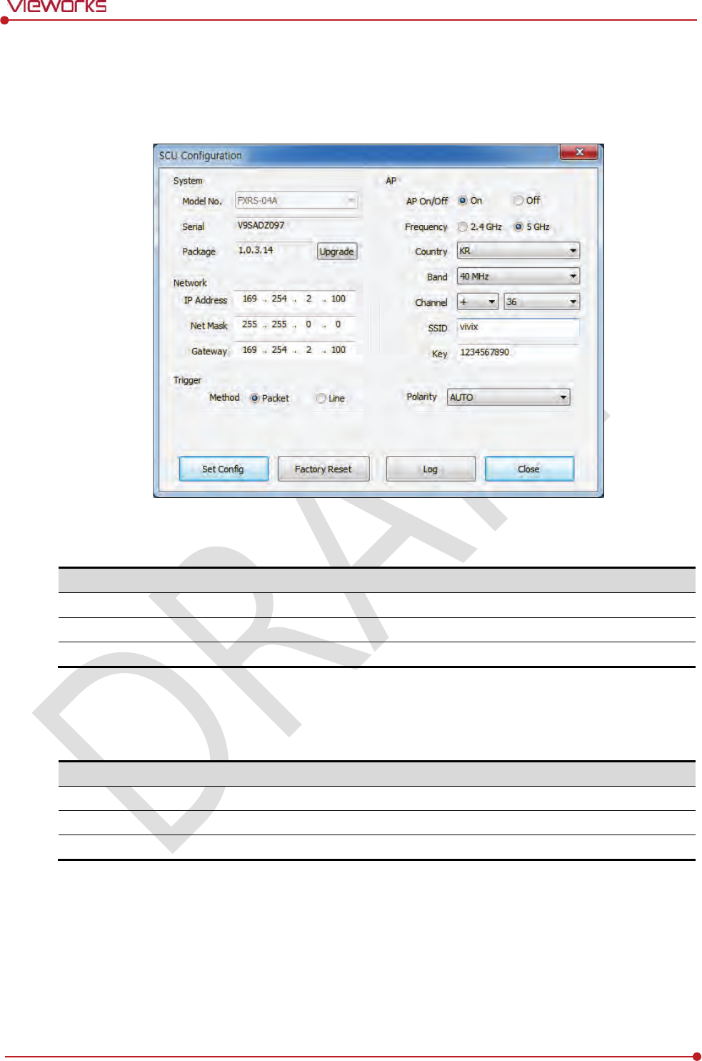
Rev.1.0
Page 83 of 151 VW40-152-009
VIVIX-S 1012N User Manual
5.2 SCU Setting
5.2.1 SCU Configuration
System
Checks and sets system information of SCU.
Item
Description
Model No
SCU model name
Serial No
SCU serial numbers
Package
Version information of SCU firmware package
Network
Checks and sets network information of SCU.
Item
Description
IP Address
IP address of SCU.
Net Mask
Subnet Mask of SCU.
Gateway
Gateway of SCU.
Rev.1.0
Page 84 of 151 VW40-152-009
VIVIX-S 1012N User Manual
AP
Checks and sets AP (Access Point) information of SCU.
Item
Description
AP On / Off
Selects w
hether to use SCU AP (Access Point) mode or not.
On
Turns on SCU AP
Off
Turns off SCU AP
Frequency
F
requency channel of wireless network.
2.4 ㎓
Use
s 2.4 ㎓ Frequency. (13 channels)
5 ㎓
Uses 5
㎓ Frequency. (8 channels)
Country
C
ountry code of using wireless network. (KR, US, EU, JP, CN)
Band
W
ireless network bandwidth.
20 ㎒
Default frequency band.
40 ㎒
Expands bandwidth through channel b
onding.
Channel
W
ireless communication channel
SSID
Unique
ID for wireless communication
Key
Unique
key for wireless communication (Applied to the password only.)
13 channels can be used in 2.4 ㎓ Frequency.
8 channels can be used in 5 ㎓ Frequency
The number of serviceable channels is different according to the configured country.
Channel bonding is used for enhancing transmission speed. However, the speed may be
slowed down due to the interference of surrounding channels, even if the channels have
been bonded.
Channel items (+/-) will be activated in case of using 40㎒ frequency bandwidth. You can
set whether to bond channels with the above or below one.
SSID and Key values of the detector communicated with SCU should be set as the same.
Set SSID and Key values not to be duplicated with those of the peripheral system.
SSID and Key values should be input as capital / small alphabet letters, numeric
characters and only “-“, “_” among special letters up to 20.
Wireless network setting should be done by an engineer who understands the wireless
communication and its related technique. Unless the network is set properly, a
communication error would occur or the image quality would be affected.
Rev.1.0
Page 85 of 151 VW40-152-009
VIVIX-S 1012N User Manual
Trigger
Configures trigger information for integration between SCU and X-ray generator.
Item
Description
Method
Trigger mode
Packet
Software Trigger mode
Line
Hardware Trigger mode
Polarity
P
olarity of trigger signal
Auto (Default)
Recognizes polarity automatically and handles it. (Default value)
Active High
Handles
polarity of Active High
Active Low
H
andles polarity of Active Low
Configuration value of trigger is applied only when Exposure mode is set DR Trigger.
Configuration value of trigger is not applied when using AED mode.
The setting of Trigger should be done by an engineer who understands about the x-ray
generator device well. Unless the device and detector are set correctly, an integration
error of x-ray generator would occur or the system operation would be affected.
Command Buttons
Item
Description
Set Config
Updates by t
ransmitting current setting values to SCU.
Factory Reset
Resets SCU to factory
default settings.
Log
C
hecks the logs of SCU.
C
lose
Close
s the window of SCU Configuration. If Set Config is not performed, the
changed setting value is not transmitted to SCU.
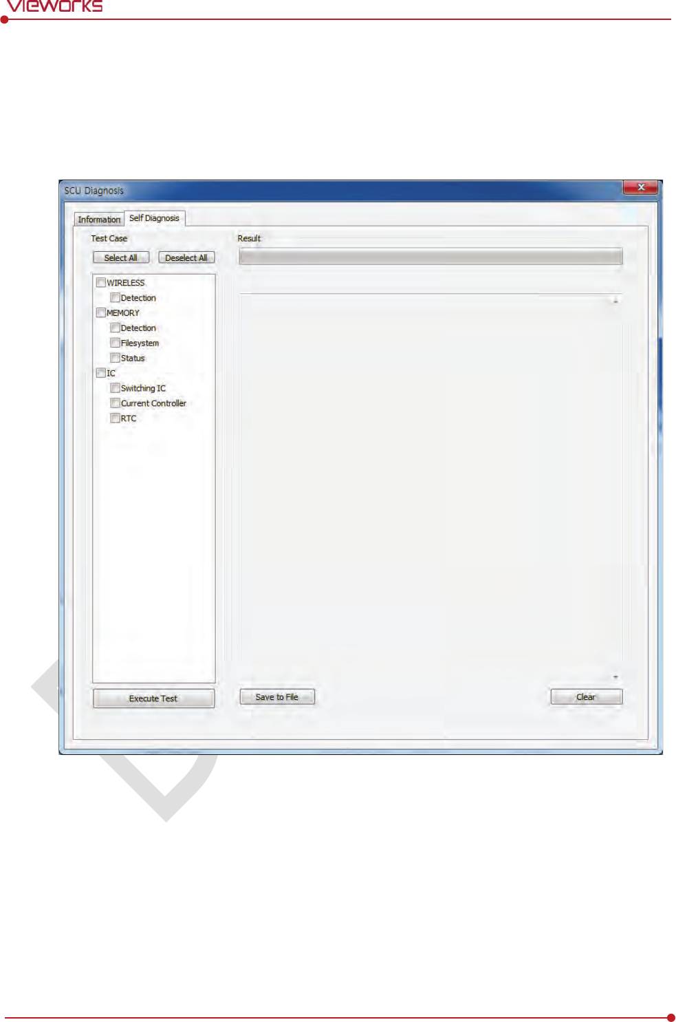
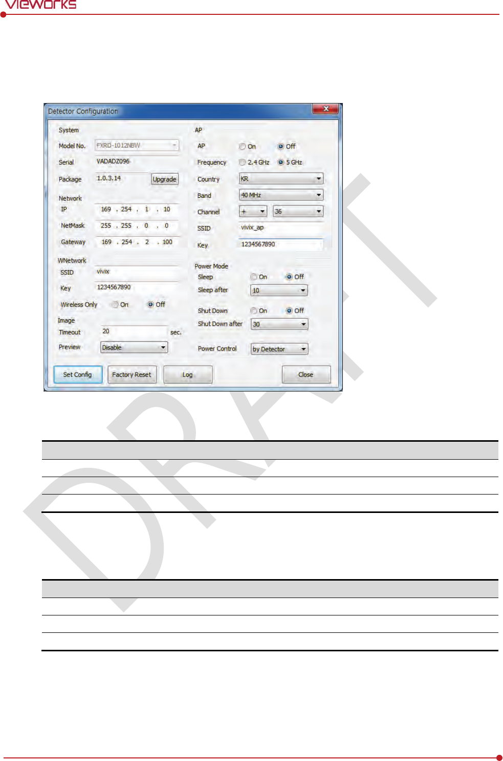
Rev.1.0
Page 87 of 151 VW40-152-009
VIVIX-S 1012N User Manual
5.3 Detector Setting
5.3.1 Detector Configuration
System
Checks and sets system information of the detector.
Item
Description
Model No
Detector model name
Serial No
Detector serial numbers
Package
Version information of
the detector firmware package
Network
Checks and sets network information of the detector.
Item
Description
IP Address
IP address of
the detector
Net Mask
Subnet Mask of
the detector
Gateway
Gateway of
the detector

Rev.1.0
Page 88 of 151 VW40-152-009
VIVIX-S 1012N User Manual
WNetwork
Sets AP (Access Point) information of wireless communication from the detector.
Item
Description
SSID
Configures w
ireless network ID AP from the detector.
Key
Configures w
ireless network key value of AP from the detector.
Wireless Only
Configures the
wireless communication method of the detector.
On
The detector is operated in a wired way when a tether interface cable is
connected.
Off
The detector is operated in a wireless way when a tether interface cable is not
connected.
AP
Checks and sets AP (Access Point) of detector information.
Item
Description
AP On
/ Off
Decides w
hether to run the detector on AP (Access Point) mode.
On
Turns on
the detector AP
Off
Turns off
the detector AP
Frequency
F
requency channel of wireless network
2.4 ㎓
Use
s 2.4 ㎓ Frequency. (Up to 13 channels)
5 ㎓
Uses 5
㎓ Frequency. (Up to 8 channels)
Country
C
ountry code of wireless network (KR, US, EU, JP, CN)
Band
W
ireless network bandwidth
20 ㎒
Basic
Frequency Band
40 ㎒
Expands
bandwidth through channel bonding.
Channel
W
ireless network channel
SSID
W
ireless network ID
Key
W
ireless network key value (Applied to the password only.)
13 channels can be used in 2.4 ㎓ Frequency.
8 channels can be used in 5 ㎓ Frequency
The number of serviceable channels is different according to the configured country.
Channel bonding is used for enhancing transmission speed. However, the speed may be
slowed down due to the interference of surrounding channels, even if the channels have
been bonded.
Channel items (+/-) will be activated in case of using 40㎒ frequency bandwidth. You can
set whether to bond channels with the above or below one.
SSID and Key values of the detector for communicating with SCU wirelessly (WNetwork)
should be set as the same.
Rev.1.0
Page 89 of 151 VW40-152-009
VIVIX-S 1012N User Manual
Set SSID and Key values not to be duplicated with those of the peripheral system.
SSID and Key values should be input as capital / small alphabet letters, numeric
characters and only “-“, “_” among special letters up to 20.
Wireless network setting should be done by an engineer who understands the wireless
communication and its related technique. Unless the network is set properly, a
communication error would occur or the image quality would be affected.
Image
Checks and sets the time limit of image transmission as well as decides whether to use the Preview item.
Item
Description
Time (sec.)
The limited time of completing image transmission.
Preview (Enable / Disable)
Sets
whether to use the wireless communication way for sending preview
images
.
After starting image transmission, the detector ignores the information of image re-
transmission request if the following conditions are fulfilled.
If the time limit of image transmission does not exceed.
If the image is not transmitted completely.
Power Mode
Checks and sets the management information about the power of detector.
Item
Description
Sleep
Decides whether to use the sleep mode function of the
detector. (On / Off)
Sleep after
(min.)
If the detector is not used for the specific setting time, it is
turned to the sleep
mode
. This mode activates only when the sleep mode is set. (10 / 15 / 20 / 25 /
30
min.)
Shut Down
Sets
whether to use the shut down function in the detector. (On / Off)
Shut Down after
(min.)
The
power of detector is off if it is not used within the setting time. This menu
is
activated while the Shut Down function is used. (30 / 60 / 90 / 120 min.)
Power Control
Sets standards of power supply to the detector
.
by
Detector
T
he detector is operated by power from SCU and battery.
I
f the power from SCU and battery is blocked, the detector is turned off.
by
SCU
The detector is operated by power from SCU with connecting a tether cable
. If
the power from SCU is blocked, the detector is turned off
.
You can prevent unnecessary battery consumption by using the Sleep function.
When SCU supplies power to the detector with connecting a tether interface cable, the
Shutdown function cannot be operated.
If Power Off is set to by Detector and the tether interface cable is disconnected, you can
keep using the detector by the power of battery. In this case, you can turn off the
detector by pressing the power button for 3 seconds.
Rev.1.0
Page 90 of 151 VW40-152-009
VIVIX-S 1012N User Manual
If Power Off is set to by SCU, the battery cannot supply power to the detector. In this
case, you should connect the tether interface cable to supply power of SCU to the
detector.
Wireless network setting should be done by an engineer who understands the wireless
communication and its related technique. Unless the network is set properly, a
communication error would occur or the image quality would be affected.
5.3.2 Detector Power Save Function
The consumption of a battery pack can be reduced by using the power save function.
The power save function is operated only when the battery supplies power to the
detector. In other words, the power save function cannot be operated if a tether interface
cable supplies power to the detector.
Mode
Mode
Meaning
Normal
The detector can be operated
and take an image at any time.
Sleep
The detector cannot be operated. User can take an image by
disabling the Sleep mode.
Shut Down
The detector has been turned off.
User can take an image after the detector is rebooted.
Entry Condition of Power Save Mode
Mode
Meaning
Normal
-
Sleep
The detector turns to sleep mode if not used for the setting time (Sleep after).
Shut Down
The detector is turned off if not used for the
setting time (Shutdown after) under the
sleep mode. However, if the detector is not used for the setting time (Shutdown after)
under the sleep off state, the detector is turned off.
Checks Power Save Mode
Mode
Meaning
Normal
All LED l
amps are turned on.
Sleep
Power LED (Green) is blinking.
VXvue (Vieworks Viewer) indicates the state of sleep mode.
VIVIX
SDK indicates the state of sleep mode.
Shut Down
All LED l
amps are turned off.

Rev.1.0
Page 91 of 151 VW40-152-009
VIVIX-S 1012N User Manual
Setting Items of Power Save Function
Mode
Meaning
Normal
-
Sleep
Selects the function
On (use) or Off (not use).
Sleep after (min.)
Sleep mode is activated if the detector is used during the setting time.
Shut Down
Selects
the function On (use) or Off (not use).
Shutdown after (min.)
The detector is turned off if it
is not used during the setting time. This menu is
activated
while the Shut Down function is used. (30 / 60 / 90 / 120 min.
Disabling Power Save Function
Mode
Meaning
Normal
-
Sleep
Turns off sleep mode from VXvue (Vieworks Viewer).
Calls the function
from VIVIX SDK to turn off sleep mode.
Shut Down
Reboots the detector by pressing a power button on the detector.
Other Information
Mode
Default value
Turnaround time
Power consumption
Normal
-
-
24V, 300mA (
Standby)
24 V, 600mA (
While taking
images
)
Sleep
OFF / 10min.
Approx. 10 sec.
24V, Max. 15
0mA
Shut Down
OFF / 30
min.
Approx.
15 sec.
-
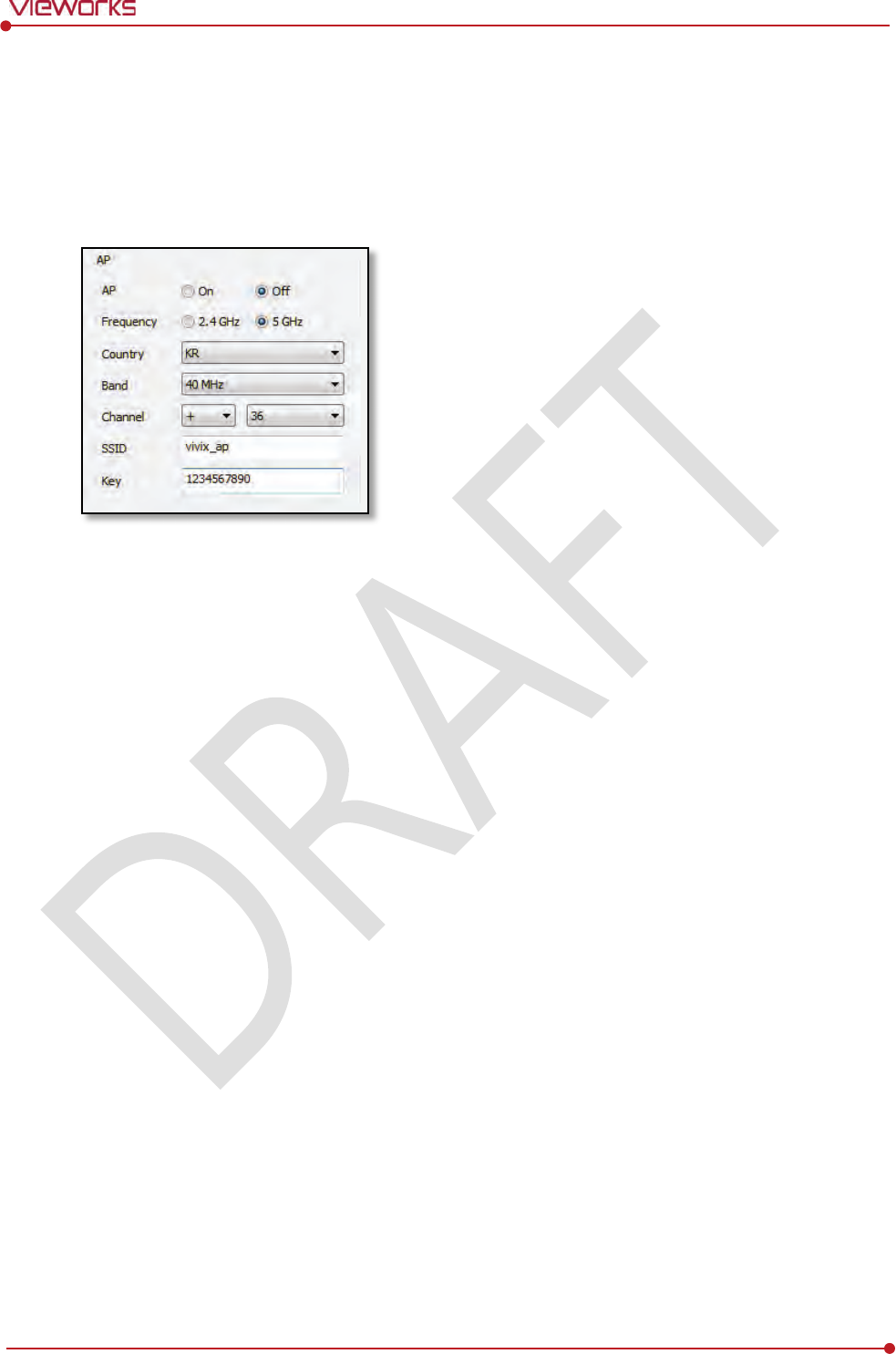
Rev.1.0
Page 92 of 151 VW40-152-009
VIVIX-S 1012N User Manual
5.4 Changing the Wireless Setting
5.4.1 Switching to the Detector AP Mode
You can change the detector mode as AP by following the two ways.
Choose the AP option as On or Off from the Detector Configuration dialog in VIVIX Setup program.
Press the AP button on the detector for 5 seconds to set the Detector AP mode. The LED of detector
AP blinks in a blue color while the mode is being switched, and turns on blue after the mode is
compeleted to be set.
5.4.2 Synchronizing the Wireless Setting
Synchronize the wireless setting with a tether interface cable as follows.
1 Connect the detector and SCU with a tether interface cable.
2 Press the detector AP button for 5 seconds after the detector is turned on.
3 The LED of detector AP blinks while processing synchronization.
4 The sync information is saved automatically after it is transmitted to the detector where SSID and KEY
of SCU are connected.
5 The detector is switched to the wireless communication mode.

Rev.1.0
Page 93 of 151 VW40-152-009
VIVIX-S 1012N User Manual
6. Calibration
This chapter gives information about the calibration methods after installing a detector.
Calibration Dialogue
Detector Configuration
Calibration Guide
Calibrating by Loading the Calibration Data
Direct Calibration
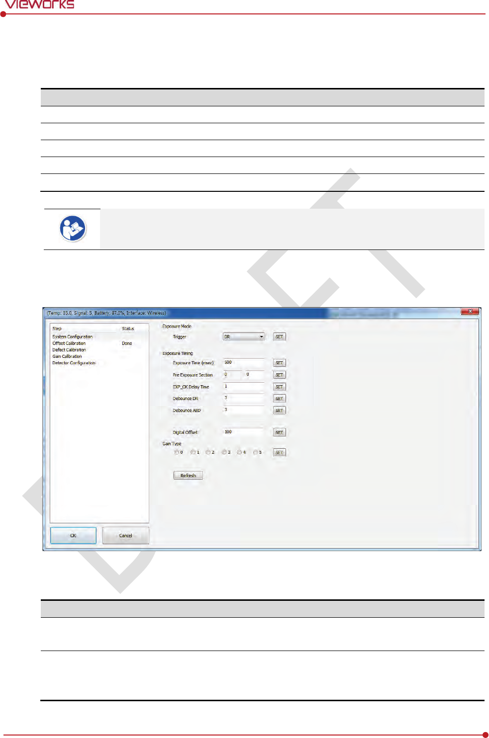
Rev.1.0
Page 94 of 151 VW40-152-009
VIVIX-S 1012N User Manual
6.1 Calibration Dialogue
Use the following menus to configure the system and process calibrations.
Menu
Description
System Configuration
Configures the exposure mode, exposure
-related time and Gain type.
Offset Calibration
Processes
Offset calibration.
Defect Calibration
Processes
calibration for defect data of the detector.
Gain Calibration
Processes
calibration for image sensitivity.
Detector Configuration
Configures the detector information related to calibration and image.
The menu status is displayed as Done when each calibration is finished. You cannot
operate the detector if the status is not displayed as Done.
6.1.1 System Configuration Dialogue
Configure the generator interface information from System Configuration in Step.
Exposure Mode
The VIVIX-S 1012N detector provides two types of mode for taking images as follows.
Mode
Description
AED
Detects X
-ray automatically without connecting the detector to X-ray generator.
The detector acquires images after the automatic detection.
DR Trigger
D
etects the X-ray exposure signal of X-ray generator in advance by connecting the
detector to X
-ray generator with a generator interface cable.
The
detector acquires images after preparing exposure with the exposure signal.
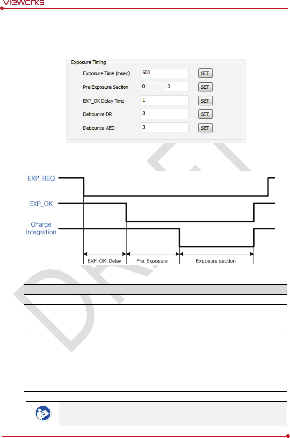
Rev.1.0
Page 95 of 151 VW40-152-009
VIVIX-S 1012N User Manual
Exposure Timing
To take images exactly, set the timing information for exposure.
The information can be different depening on the characteristics of the X-ray generator.
Exposure Timing Diagram
Exposure Timing Items
Item
Default
Description
Exposure section
50
0㎳
T
ime to acquire X-ray by the detector.
Pre Exposure section
0
㎳
Standby time after the detector sent EXP_OK signal to the generator.
EXP OK Delay section
1
㎳
The delayed time to receive EXP_OK signal from the detector after the
generator sent EXP_REQ signal to the detecto
r.
Debounce_DR
3
㎳
The required time to
check signals from the generator for preventing
image
acquisition from external noise. It can be used when DR Trigger
mode is selected only
.
Debounce_AED
3
㎳
The required time to check sensor signal from X
-ray to prevent image
acquisition
from external noise. It can be used when AED mode is
selected only
.
Exposure section should be set longer than the maximum exposure time to prevent X-
ray
loss.
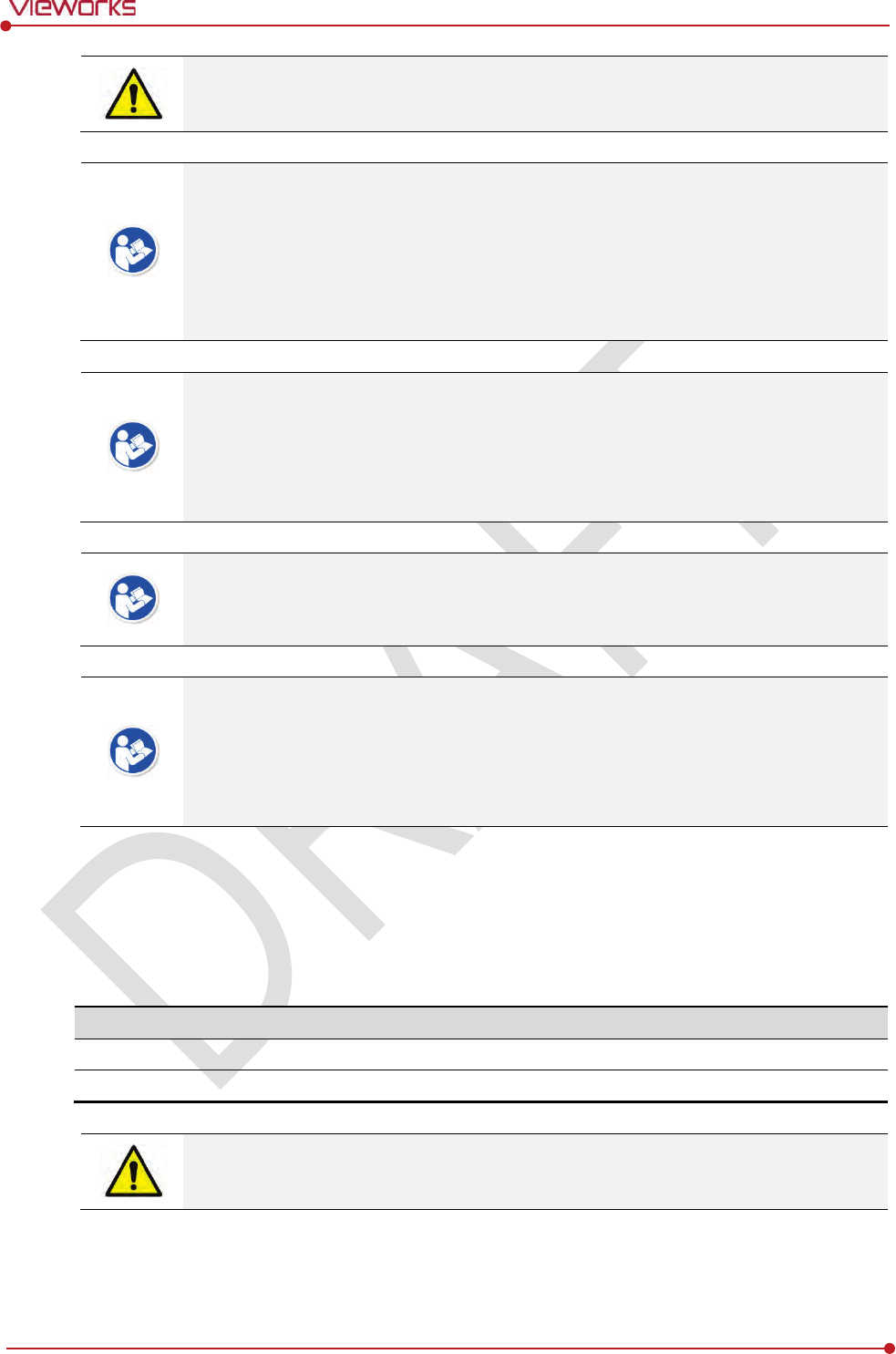
Rev.1.0
Page 96 of 151 VW40-152-009
VIVIX-S 1012N User Manual
When Exposure section is changed, make sure to create new calibration data by
processing Offset calibration and Gain calibration to get optimized images.
Pre Exposure section can be used when the time delays until the generator receives EXP-
OK signal from the detector and generates X-ray. Although Pre Exposure section
is set as
0㎳ normally, it is recommended to measure and set the actual delay time of X-ray
generation to achieve the best performance of the detector. The detector sends EXP_OK
signal to the generator, then acquires X-ray after the setting time in Pre Exposure
section.
EXP OK Delay section is the delayed time between the detection time of exposure
request signal (EXP_REQ) from the X-ray generator and the time before sending exposure
respond signal (EXP_OK) to the X-ray generator. Some X-ray generators need time to
prepare detecting EXP_OK signal after sending EXP_REQ signal. This time is determined
according to the specifications of X-ray generator.
Debounce_DR is used for removing the trigger signal due to external noise when the
exposure mode is set as DR Trigger. If the value is set to less than 3㎳, the detector may
acquire undesirable images.
Debounce_AED is used for removing trigger signals due to external noise when the
exposure mode is set as AED. If the Debounce_AED value is set longer than the X-ray
exposure time, the detector cannot acquire images. If unwanted images are acquired
without X-ray exposure while the equipment is operated, set Debounce_AED with 1㎳
increments. However, we recommend you not to set the value more than 10㎳.
Gain Type
You can select the Gain Type to adjust sensitivity of the detector for acquiring X-ray images with desired
brightness according to the specifications of X-ray generator or the object type.
The following table describes the sensitivity ratio of each Gain Type.
Gain Type
0
1
2
3
4
5
1012NA(W) (CsI)
0.96
1.2
1.44
1.6
1.8
3.6
1012NB(W)
(Gadox)
0.82
1.0
1.29
1.5
1.8
3.0
To acquire the optimized images, carry out the Offset calibration and Gain calibration
again after changing Gain Type.
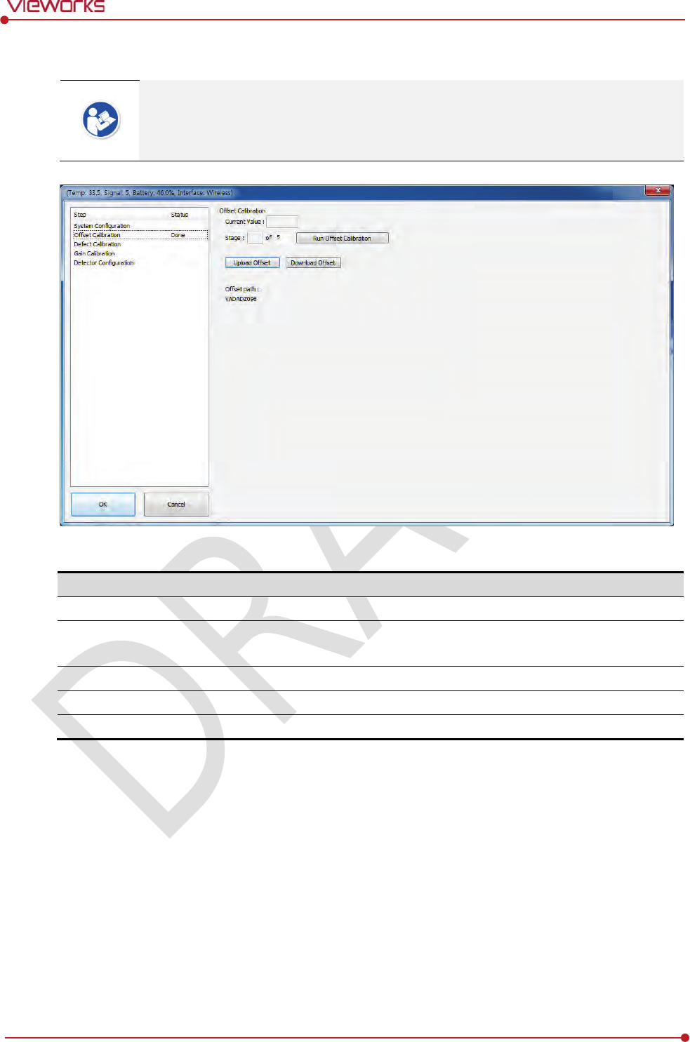
Rev.1.0
Page 97 of 151 VW40-152-009
VIVIX-S 1012N User Manual
6.1.2 Offset Calibration Dialogue
Vieworks provides the Defect Map data stored in the detector. However, we recommend
you to carry out the Offset calibration by yourself as the detector condition can be
different by the operating method or use environment.
Offset Calibration
Item
Description
Current value
Shows value
when performing the manual Offset calibration.
S
tage
Select
s the performance frequency of manual Offset calibration and
shows each
calibration stage.
Run Pre
-offset Calibration
Performs the manual O
ffset calibration.
Load Pre
-offset
Downloads the O
ffset data stored in the detector.
O
ffset Path
Shows the
path of the applied Offset data.
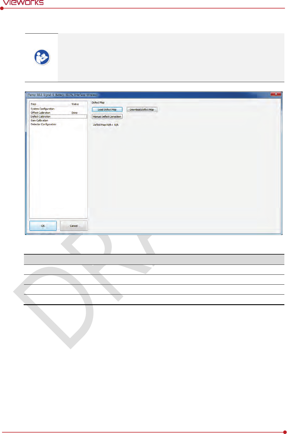
Rev.1.0
Page 98 of 151 VW40-152-009
VIVIX-S 1012N User Manual
6.1.3 Defect Calibration Dialogue
Vieworks provides the Defect Map data stored in the detector. However, you should
download the data as the calibration cannot be performed in the detector automatically.
This Defect Map data has been generated through stringent test in the production stages
of detector. However, new defect may be newly formed while using the detector. In this
case, make sure to calibrate defects in person and generate a new defect map.
Defect Map
Item
Description
Load Defect Map
Loads the Defect Map calibration data
located in the defect map path.
Download Defect Map
Downloads the Defect Map calibration
data stored in the detector.
Manual
Defect Correction
Calibrates the defect manually.
Defect Map Path
Shows the
path of applied Defect Map data.
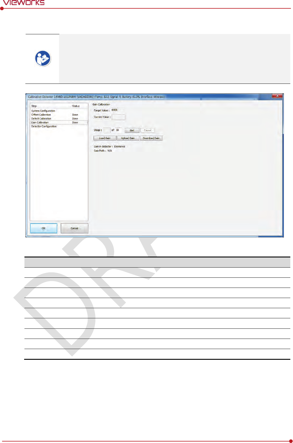
Rev.1.0
Page 99 of 151 VW40-152-009
VIVIX-S 1012N User Manual
6.1.4 Gain Calibration Dialogue
Vieworks provides the Gain data stored in the detector. However, you should download
the data as the calibration cannot be performed in the detector automatically.
This data is provided in case the Gain calibration cannot be performed. You should do
the Gain calibration in person as the detector condition can be different by the operating
method or use environment.
Gain Calibration
Item
Description
Target
Value
Shows the target value of Gain calibration. (Recommended :
8000 or higher)
Current Value
Shows
value after the exposure when processing the manual Gain calibration.
S
tage
Select
s the number of manual Gain calibration and shows each calibration stage.
Get
Starts the manual Gain calibration.
Cancel
Cancels
the manual Gain calibration.
Load Gain
Loads the Gain calibration data
located in the Gain path.
Upload Gain
Uploads the Gain calibration data to the detector for using portable mode.
Download Gain
Downloads the Gain calibration
data stored in the detector.
Gain
Path
Shows the
path of applied Gain data.
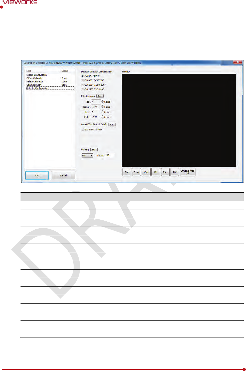
Rev.1.0
Page 100 of 151 VW40-152-009
VIVIX-S 1012N User Manual
6.2 Detector Configuration
From the Detector Configuration dialog, you can configure the detector and check the images before or
after doing calibration.
Function
Description
Detector Direction Compensation
Set
s the displayed direction of image.
Effective Area
Set
s effective area of an image.
Offset Refresh Setting
Set
s conditions of automatic Offset Refresh.
Time Interval (min.)
Checks cycle of temperature change
Temperature Interval (℃)
Differ
ence of over-temperature.
Number of shot
Number of Offset Refresh.
Masking (On / Off)
Set
s outside of the effective area to specific values.
OSF
Chooses whether to use OSF or not.
Set
S
aves the setting values to the detector.
Pan
Moves an image to the desired location.
Zoom
Extends or
constract an image.
W/L
Adjusts window level of an image.
Fit
Displays an image by adjusting it to the screen.
E.A.
Sets
the effective area of an image with a mouse.
ROI
Sets the image area of interest.
E.A (Effective Area)
Displays effective area of
an image only.
Rev.1.0
Page 101 of 151 VW40-152-009
VIVIX-S 1012N User Manual
You can only change the displayed direction of an image from Detector Direction
Compensation. The direction of an original image cannot be changed.
Effective Area can be changed within the effective range which has been configured at
the time of the first shipment of detector.
Once Use offset refresh is used, the offset refresh is processed automatically as follows.
Checks temperature difference of the detector between current temperature and the
previous one at the time of offset refresh in every setting time from Time Interval.
If the temperature difference is more than the one set in Temperature Interval, the
offset refresh is carried out a number of times set in Number of shot.
If you use VXvue, a pop-up message will be displayed before the offset refresh.
Auto offset refresh will be performed by clicking OK button.
OSF is the auxillary function for stabilizing pixel value of an image to the default value
rapidly.
The pixel value can be displayed equally by using OSF under the environment where the
pixel value of X-ray image is required to display.
Whether to use OSF or not does not affect the X-ray image quality.

Rev.1.0
Page 102 of 151 VW40-152-009
VIVIX-S 1012N User Manual
6.3 Calibration Guide
The different installation environment of each detector and unique features of the X-ray generator device
can affect the acquired images. Therefore, the certified engineer from Vieworks should do the detector
calibration after installing it. Otherwise, the image quality can be affected seriously.
Vieworks provides two types of calibration for performing calibration.
Performing calibration by loading the calibration data CD provided by Vieworks.
The service engineer proceeds calibration and generate calibration data.
We strongly recommend the service engineer to carry out the calibration in person since
the detector condition and image quality can be different by the operation method or
use environment.
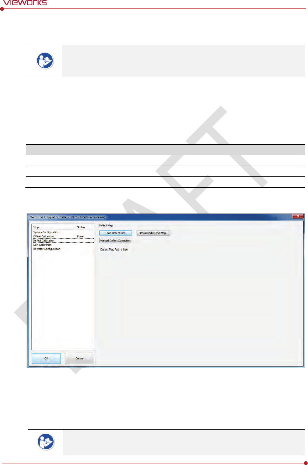
Rev.1.0
Page 103 of 151 VW40-152-009
VIVIX-S 1012N User Manual
6.4 Calibrating by Loading the Calibration Data
Vieworks provides the calibration data stored in the detector. Although the Offset
calibration is performed automatically, you need to download both Defect and Gain
calibration data since their calibration cannot be performed in the detector automatically.
6.4.1 Preparing Calibration Data
Among the three types of calibration data stored in the detector, download the Defact Map and Gain
calibration data to local HDD.
It is not necessary to download the Offset calibration data since the data is used in the detector.
File
Description
Offset
Detector Offset data
Gain
Calibration
data for image sensitivity
Defect Map
Defect calibration map data
6.4.2 Loading Defect Calibration Data
1 Select Defect Calibration from the Step list.
2 Click Download Defect Map button to assign the path of local HDD, and download the Defect Map
calibration data.
3 Click Load Defect Map button to load the calibration data.
The calibration menu status is displayed as Done when the Defect calibration data is
loaded completely.
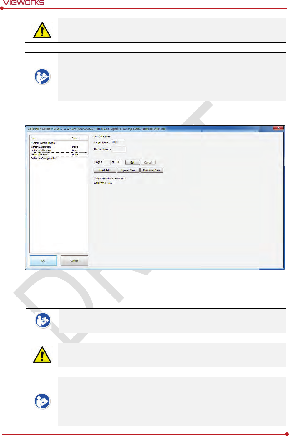
Rev.1.0
Page 104 of 151 VW40-152-009
VIVIX-S 1012N User Manual
Be sure to select the Defect Map data file provided with a detector. If the file has a wrong
serial number or you select a wrong file, an error message will be displayed.
Vieworks provides the Defect Map data stored in the detector. However, you should
download the data as the calibration cannot be performed in the detector automatically.
This Defect Map data has been generated through stringent test in the production stages
of detector. However, new defect may be newly formed while using the detector. In this
case, make sure to calibrate defects in person and generate a new defect map.
6.4.3 Loading Gain Calibration Data
1 Select Gain Calibration – Normal from the Step list.
2 Click Download Gain button to assign the path of local HDD, and download the Gain calibration data.
The calibration menu status is displayed as Done when the Gain calibration data is
completed to be loaded.
Be sure to select the Gain calibration data file provided with a detector. If the file has a
wrong serial number or you select a wrong file, an error message will be displayed.
Vieworks provides the Gain calibration data stored in the detector. However, you should
download the data as the calibration cannot be performed in the detector automatically.
This data is provided in case the Gain calibration cannot be performed. You should do
the Gain calibration in person as the detector condition can be different by the operating
method or use environment.
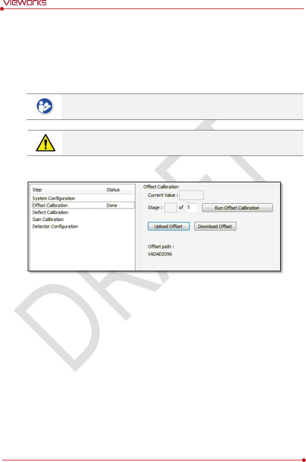
Rev.1.0
Page 105 of 151 VW40-152-009
VIVIX-S 1012N User Manual
6.5 Direct Calibration
6.5.1 Prepration
Precheck the state of X-ray generator and console.
Precheck the state of X-ray tube.
It is recommended you to check if X-ray dose value of the generator is exact by using the
device like a dose meter.
Make sure to preheat the detector for 30 minutes before starting calibration. The result of
measurement can be incorrect if the detector is not preheated sufficiently.
6.5.2 Offset Calibration
1 Set the number of Stage as 5 in the Offset Calibration area.
2 Click Run Offset Calibration button and progress the Offset calibration.
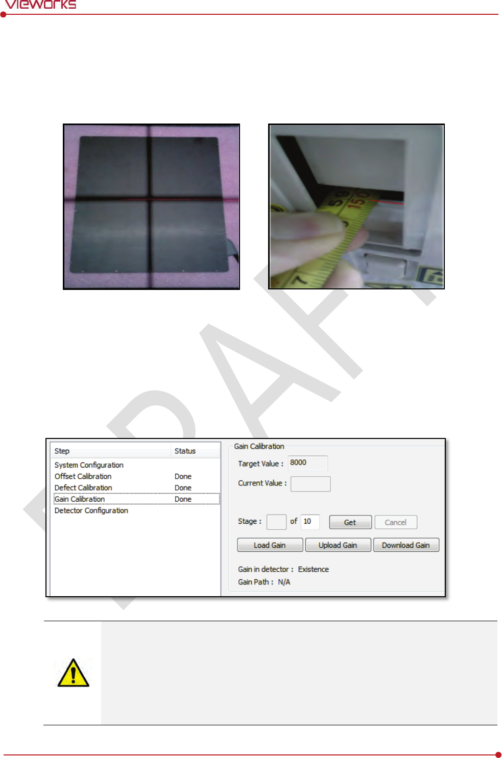
Rev.1.0
Page 106 of 151 VW40-152-009
VIVIX-S 1012N User Manual
6.5.3 Gain Calibration
1 Put a collimator on center of the detector, and open the collimator completely.
2 Adjust SID as 130㎝ ~ 150㎝ to make X-ray exposure range include the detector.
3 Remove any objects or foreign materials between the tube and the detector.
4 Choose Gain Calibration -Normal.
5 Set the tube voltage of X-ray generator as 70㎸ ~ 80㎸.
6 While acquiring images, adjust the X-ray dose condition (㎃ or ㎳) until Current Value of the Gain
Calibration area is formed between 8000±200.
7 Set the exposure number of Stage as 10 when the adjustment of exposure condition is completed.
8 Click Get button, and keep making an X-ray exposure at 15 sec intervals.
9 Save the Gain Calibration data as a file.
Make sure to progress Gain Calibration again if the cases below are applicable.
When the settings of Exposure Section or Gain Type is changed from the VIVIX Setup
program.
When the exposure devices like X-ray generator are repaired.
When the exposure environment is changed.
When the service engineer decides that it is need to progress Gain Calibration.
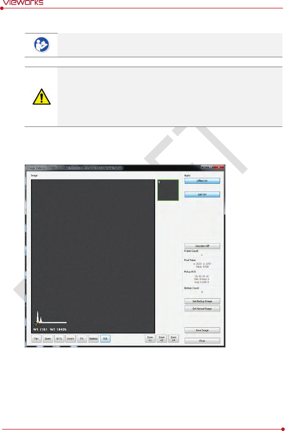
Rev.1.0
Page 107 of 151 VW40-152-009
VIVIX-S 1012N User Manual
6.5.4 Auto Defect Correction
While operating the detector, defect pixels may appear on the image. In this case, use the
defect auto correction to calibrate the defect pixels.
Be sure to check the followings before acquiring the FLAT image.
Preheat the detector for 30 minutes or more.
The recommend SID is 150 ㎝ (distance between X-ray tube and detector)
Open the collimator of X-ray tube completely.
Align the center of the detector with the center of collimator.
Keep everything away from the detector surface.
1 Make an exposure of FLAT images from the Image dialog box.
2 Click Save Image button to save images to the user-defined folder. (saved as a raw file.)
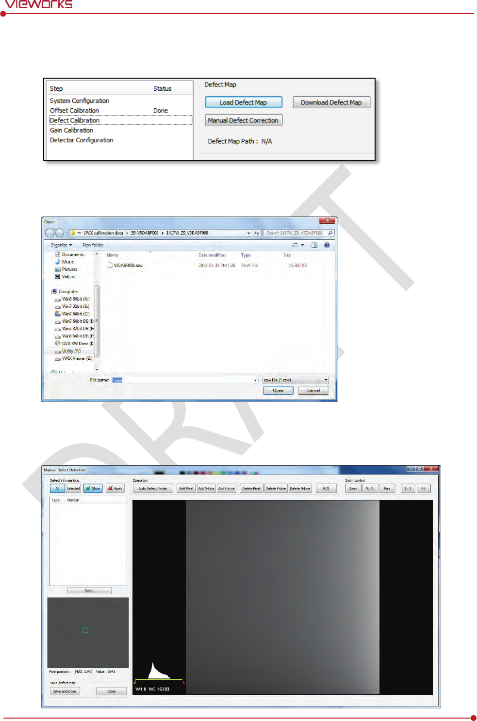
Rev.1.0
Page 108 of 151 VW40-152-009
VIVIX-S 1012N User Manual
3 Close the Image dialog box, and open the Calibration dialog box.
4 Choose Defect Calibration as follows and click Manual Defect Correction button.
5 Move to the folder where the raw file is saved and select the file.
6 The Manual Defect Detection screen will be displayed.
7 Click Show and Apply buttons on the top left and then click Auto Defect Finder button.
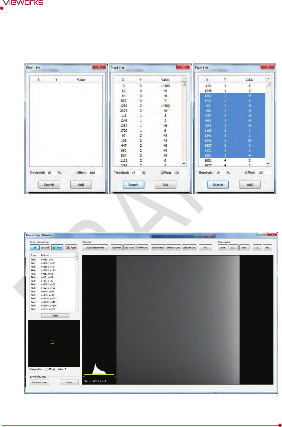
Rev.1.0
Page 109 of 151 VW40-152-009
VIVIX-S 1012N User Manual
8 Input 15% for Threshold, and 100 for Offset at the bottom of the Pixel List screen.
9 Click Search button at the bottom of the screen. The coordinates of defect pixels and Gray level values
are displayed on Pixel list.
10 While pressing the Ctrl or Shift key, select the coordinate of defect pixels to be added to Defect Map.
11 Click Add button to add the selected items to Pixel List in Manual Defecct Detection.
12 Check if the selected defect pixels are added to the pixel list on the left.
13 Click Save and Close button at the left bottom.
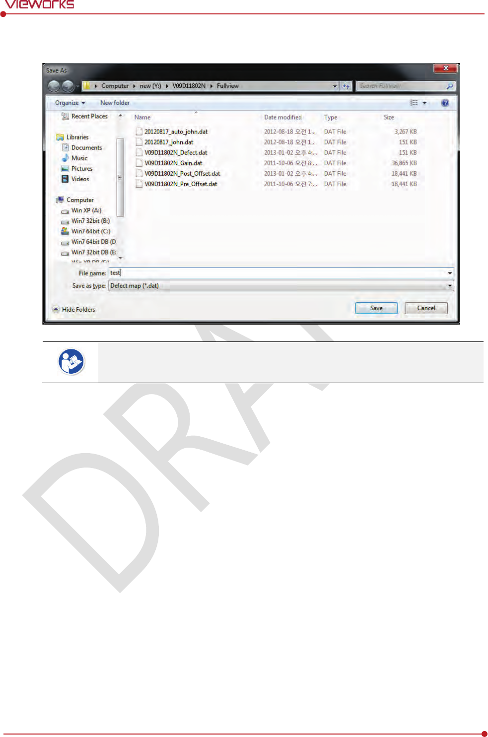
Rev.1.0
Page 110 of 151 VW40-152-009
VIVIX-S 1012N User Manual
14 Save the newly generated Defect Map data to the path where the Calibration data has been stored.
It is recommended to save the newly generated Defect Map data with a differe
nt name to
preserve the past Defect Map data.
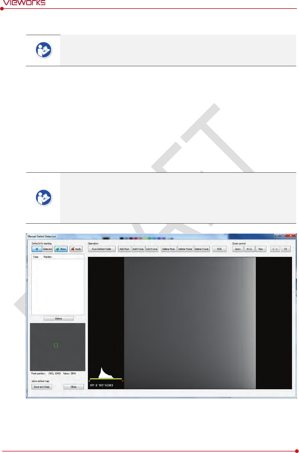
Rev.1.0
Page 111 of 151 VW40-152-009
VIVIX-S 1012N User Manual
6.5.5 Manual Defect Correction
Execute Manual Defect Detection when the defect pixels are visible to the naked eye
even the automatic defect correction is processed. Manual Defect Detection is divided
into the pixel type and line type.
Manual Defect Correction in Pixel Type
1 Make sure to carry out the automatic defect correction from 1 to 14 steps first.
2 Click Show and Apply buttons on the left top of Manual Defect Detection.
3 Press and hold the right mouse button and move it to left/right/top/ bottom in the FLAT image to
adjust the brightness until you can verify the image with the naked eyes.
4 Click Add Pixel Button.
5 Use the Zoom or Pan function properly to find and click the location of defect pixel. Red point will be
displayed and coordinate of the pixel will be added on the Detect Map List on the left upper.
6 Click Save and Close button to save the Defect Map data with a new name.
If a selected pixel has a difference in the brightness or gray level value (more than 15%)
compared to the adjacent pixels, the pixel may be regarded as a defect pixel.
A window located on the left top will magnify and display the pixel where the mouse
pointer is located. The coordinate and Gray level value of the pixel will be displayed
under the window.
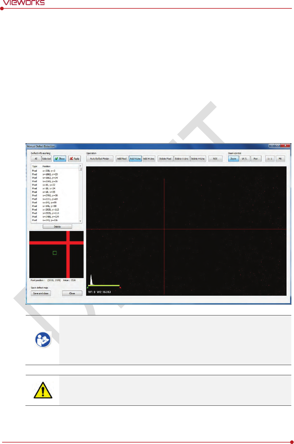
Rev.1.0
Page 112 of 151 VW40-152-009
VIVIX-S 1012N User Manual
Manual Defect Correction in Line Type
1 Make sure to carry out the automatic defect correction from 1 to 12 steps first.
2 Click Show and Apply buttons on the left top of Manual Defect Detection.
3 Press and hold the right mouse button and move it to left/right/top/bottom in the FLAT image to
adjust the brightness until you can verify the image with the naked eyes.
4 Find and move to the start point of defect lines (line type) on the image.
5 Click Add V-Line or Add H-Line button.
6 Press and hold the left mouse button on the first defect pixel, move the mouse to the opposite
direction and release the mouse button on the last pixel of Line Defect pixel.
7 A red line will be displayed on the image and check if pixels on the line are added to the Defect Pixel
list.
8 Click Save and Close button to save the newly generated Defect Map data with a new name.
If a selected pixel has a difference in the brightness or gray level value (more than 15%)
compared to the adjacent pixels, the pixel may be regarded as a defect pixel.
A window located on the left top will magnify and display the pixel where the mouse
pointer is located. The coordinate and Gray level value of the pixel will be displayed
under the window.
If there are pixels existed without defect correction even though you conduct the manual
defect correction, get technical support from the person in charge of Vieworks or a
certified engineer by Vieworks.

Rev.1.0
Page 113 of 151 VW40-152-009
VIVIX-S 1012N User Manual
Functions of Manual Defect Detection
Function
D
escription
Show
Decides
whether to indicate the selected defect on the image
Apply
Decides
whether to apply Defect in the list to the calibrated image.
All
Appl
ies to all coordinates of defects added to the list
Selected
Appl
ies to relevant coordinates of the selected defects from the list only.
Auto Defect Finder
Performs the auto defect correction.
Delete
Delete
s the selected items from the list.
Add Pixel
Add
s one defect pixel to Defect Map List.
Add V
-Line
Add
s vertical line type of defect pixels to Defect Map List
Add H
-Line
Add
s horizontal line type of defect pixels to Defect Map List.
Delete Pixel
Deletes the defect pixel of a point on list of Defect Map.
Delete V
-Line
Deletes the defect pixel of vertical
line on list of Defect Map.
Delete H
-Line
Deletes the defect pixel of horizental line on list of Defect Map.
ROI
Marks the area of interest.
Zoom
Zoom in or out the image
.
W/L
Adjust
s the window level of the image to change the brightness.
Pan
Move
s the image to a desired location.
1:1
Displays the image as 1
:1 ratio.
Fit
Displays the image as
fitting it on the screen.
Save and Close
Saves the changed defect pixel information as Defect map data.
Close
Closes
the window without saving the changed defect pixel information

Rev.1.0
Page 114 of 151 VW40-152-009
VIVIX-S 1012N User Manual
7. Diagnosis, Inspection and
Maintenance
This section gives information about diagnosis, inspection & maintenance of the product.
Diagnosis
Product Inspection
Cleaning and Disinfection
Product Initialization
Replacing the Fuse of SCU
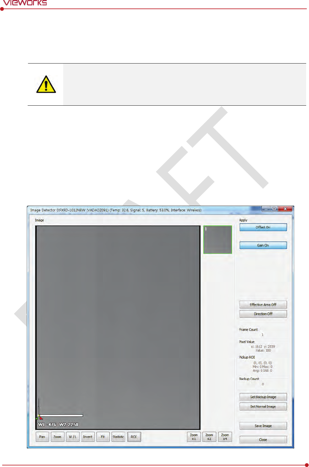
Rev.1.0
Page 115 of 151 VW40-152-009
VIVIX-S 1012N User Manual
7.1 Diagnosis
7.1.1 Image Diagnosis
Check the image quality through Diagnosis tools after installing the detector or before
usage. If the problems with regard to products or image occur during diagnosis, try to do
a calibration again. If the problems are not solved, consult the sales representative in
Vieworks or a service engineer.
You can acquire and review an image from the Diagnosis window in VIVIX Setup program.
You can review images by acquiring them through real exposure or getting Dark image by clicking Get
Normal Image button.
The number of images, pixel value and ROI value will be displayed.
The effective area or whole area of an image can be checked.
It is also available to check the image by changing its direction.
Save the reviewed image as a raw one to analyze.
You can acquire an image either applying Offset / Gain data or not.

Rev.1.0
Page 116 of 151 VW40-152-009
VIVIX-S 1012N User Manual
Dignostic Functions
Item
Description
Pan
Press and drag a mouse button to m
ove the image to the desired position.
Zoom
Press and hold
a mouse button to move the image upwards or downwards for
expanding / reducing the image.
W/L
Press and hold
a mouse button to move the image to up/down/right/left for
adjusting its window level. This function can be used without clicking W/L button,
but with the right mouse button basically.
Fit
S
ets the image to the center, which was moved by using Pan function.
Statistic
Clicks and
drags the left mouse button to set arbitrary area. The coordinate,
min/max value, average and standard deviations are displayed on
Pickup ROI at
the left side of image.
ROI
Clicks and
drags the left mouse button to set window level automatically on a basis
of min/max value of the configured area
.
Zoom
(X1 / X2 / X4)
Expands the image (2 times / 4 times / 16 times)
Effective Area
Applicabilit
y of Effective Area in Detector Configuration dialog.
On
Applies effective area of the
detector to the image.
Off
Applies whole area of the
detector to the image.
Offset
Applicability of Offset data
On
Acquires an image with applying Offset data.
Off
Acquires an image without applying Offset data.
Gain
Applicability of Gain data
On
Acquires an image with applying Gain data.
Off
Acquires an image without
applying Gain data.
Direction
Applicability of
Detector Direction Compensation in Detector Configuration dialog.
On
The image is
displayed according to the configured direction.
Off
The image is displayed as a default direction. The image starting point (0,0) is
located on the left top of the image.
Get Normal Image
Acquires a d
ark image without X-ray shooting.
Save Image
Saves the image as a raw one.
Close
Close
s the Diagnosis dialog.
You can only change the displayed direction of an image in VIVIX Setup program from
Detector Direction Compensation. The direction of an original image cannot be
changed.
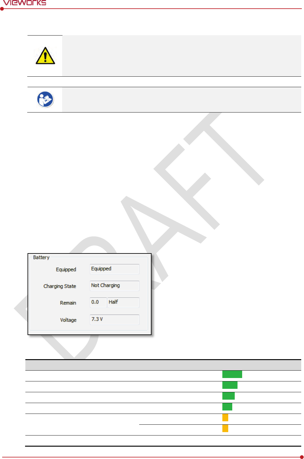
Rev.1.0
Page 117 of 151 VW40-152-009
VIVIX-S 1012N User Manual
7.1.2 Battery Pack Diagnosis
Install the battery pack to the detector and check the voltage and remaining amount of
the battery pack. Furthermore, always check the remaining amount of the battery pack
during use of the detector. If performance of the battery pack has some problems, co
nsult
the sales representative in Vieworks or a relevant engineer.
The battery pack belongs to consumables which performance will be decreased as time
passed. Make sure to check the battery life during usage.
Check remaining amout of battery pack
The battety remains is noticed as a level or percentage (%), and you can check the remains from VXvue
(Vieworks Viewer) or VIVIX SDK. It is also available to check the battery remains from the LED on the side
of detector.
If the remaining of battery is under 30% or at the 1st level:
The releated warning message is displayed from VXvue.
The releated warning message is displayed from VIVIX SDK.
The detector LED for noticing battey remains is changed from green to orange color.
If the remaining of battery is under 10%:
The detector LED for noticing battey remains blinks in orange color.
You can check the battery status from the Diagnosis dialogue in VIVIX Setup program.
Display of Bettery Remains
Level
Value
Battery Remains
LED Display
Full
5
81% ~ 100%
5th level
Half Quarter
4
61% ~ 80%
4thlevel
Half
3
51% ~ 60%
3rd level
Quarter
2
31% ~ 50%
2nd level
Low
1
11% ~ 30%
1st level
1% ~ 10%
Blink
Unknown
0
Off
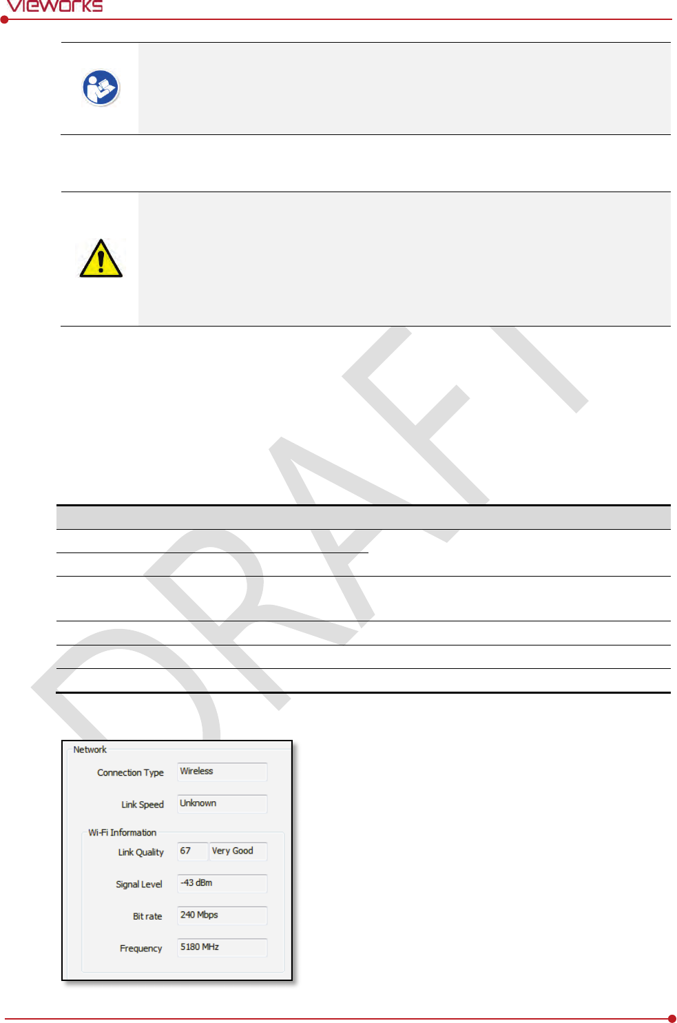
Rev.1.0
Page 118 of 151 VW40-152-009
VIVIX-S 1012N User Manual
If the remaining of battery is under 30% or at the 1st level, the system warns low battery
and the detector will be turned off automatically if the battery is being consumed for a
specific period of time. Therfore, it is recommended to change the battery when a
warning message or indicator is displayed.
7.1.3 Wireless Communication Diagnosis
In case of using the detector with wireless communication way, make sure to check the
status of wireless communication before starting to use. If the status of wireless
communication is bad, the speed of acquiring images will be very slow or failed to acquire
images. Try to check the surrounding wireless communication status not to occur
communication interference. If wireless communication module in the detector has
problems, consult the sales representative in Vieworks or a relevant engineer.
Check the Connection Status
User can check the connection status of wired or wireless detector through VXvue or VIVIX SDK.
Check the Strength of Wireless Communication Signal
The signal strength of wireless communication is provided as 5 stages or percentage (%), user can check it
through VXvue (Vieworks Viewer) and VIVIX SDK.
Level
Level
Link Quality
Meaning
Very Good
5
66 ~ 70
The communication is
running smoothly, and it
ensures performace of the image acquisition.
Good
4
56 ~ 65
Normal
3
41 ~ 55
The communication status is normal, but it does not
ensure performace of the image acquisition.
Bad
2
31 ~ 40
The communication status can become unstable.
Very Bad
1
1 ~ 30
Impossible to communicate normally.
Unknown
0
0
The
communication is disconnected.
You can check the wireless communication state from the Diagnosis dialogue in VIVIX Setup program.
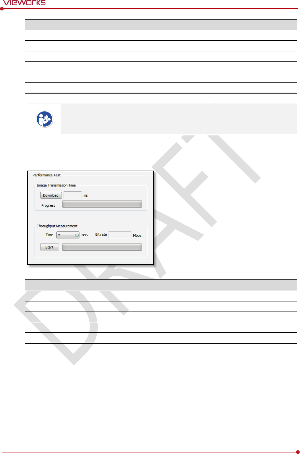
Rev.1.0
Page 119 of 151 VW40-152-009
VIVIX-S 1012N User Manual
Item
Description
Connection Type
Indicates the connection mode. (Wireless / Tether)
Link Speed
Connection status in the
wired mode. (1000Mbps / 100Mbps)
Link Quality
Link
Quality (Status of the connection quality) value
Signal
-level
Singal strength
Bit rate
Transmission /
reception speed
Frequency
Frequency of the connected
AP (Access Point)
The communication is not running smoothly when the strength of wireless communication
is under the 2nd stage. Therefore, it is required to check the surrounding wireless
communication status.
7.1.4 Communication Speed Diagnosis
The communication speed can be diagnosed from the Diagnosis dialogue in VIVIX Setup program.
Item
Description
Image Transmission Time
Image transfer rate test
Download
Download speed of the image (Detector
Workstation)
Throughput Measurement
Transmission measuring test
Time
Transmission time
Bit rate
Transmission rate
Rev.1.0
Page 120 of 151 VW40-152-009
VIVIX-S 1012N User Manual
7.2 Product Inspection
To use products safely, make sure to check the products before use. If problems occur
during inspection or the product is impossible to repair, consult the sales representative
in
Vieworks or a relevant engineer.
7.2.1 Daily Inspection
Before or after using the detector and other surrounding devices, check below items daily.
Item
Description
Detector
Ensure that there are no loose screws or breaks.
Ensure that there is no dust or foreign matter on the battery bay connector.
Ensure that there are no breaks or short-circuits in the battery bay connector.
SCU
Check if the antenna is damaged.
Cable
Ensure that cables are not damaged and cable jackets are not torn.
Ensure that the power cord plugs are securely connected to both AC inlet and AC outlet
of the equipment.
7.2.2 Performance Inspection
Check the detector and other devices periodically as follows.
Item
Period
Description
Self
-Diagnosis
Half
-yearly
Conduct Self-Diagnosis of the VIVIX Setup program for the internal
devices of the detector and check the status.
Resolution
Half
-yearly
Check the resolution of the detector through resolution chart or using a
phantom.
Sensitivity
Half
-yearly
Evaluate the characteristic of the detector through checking gray value of
the images made by X-ray dose amount reaching to the surface of the
detector.
Calibration
Half
-yearly
Updating calibration data. (Offset Gain Defect)
Proceed to calibrate when X-ray Generator, Tube, Collimator or exposure
environment are changed.
Self-diagnosis and resolution can be conducted by a user or a service engineer.
Sensitivity and calibration should be conducted by an authorized service engineer who
Vieworks grants.
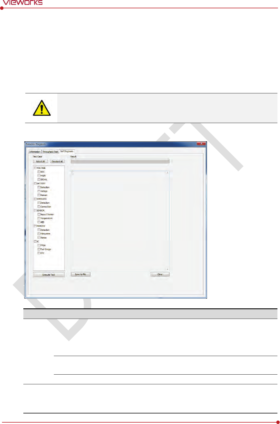
Rev.1.0
Page 121 of 151 VW40-152-009
VIVIX-S 1012N User Manual
Self Diagnosis
You can perform self diagnosis of the detector or SCU from the Diagnosis window in the VIVIX Setup
program.
1 Choose a desired item to diagnose.
2 Click Execute Test button located at the bottom of the Test Case window.
3 Check the progress and result of diagnosis for each item in the Result window.
4 Click Save to File to save the diagnosis result as a file when the self diagnosis is completed.
Self diagnosis and resolution can be conducted by a user or a service engineer.
Sensitivity and calibration should be conducted by an authorized service engineer
granted
by Vieworks.
Self-Diagnosis Items of Detector
Category
Item
Form
Expected problem
Action
Voltage
DDC
Decision
Poor condition of a tether
interface cable.
Poor power supply to the wired
operation mode.
Change a tether cable.
Contact a
service engineer.
MAIN
Decision
Poor power supply to the
processor.
Contact a
service engineer.
SIGNAL
Decision
Poor power supply to
FPGA
Contact a service engineer.
Battery
Detection
Decision
Unattached battery
Defective ciruit connected to
a battery pack.
Check if a battery is inserted.
Contact a service engineer.

Rev.1.0
Page 122 of 151 VW40-152-009
VIVIX-S 1012N User Manual
Voltage
Information
N/A
N/A
Remain
Information
N/A
N/A
Wireless
Detection
Decision
Defective wireless module
Contact a service eingineer.
Connection
Decision
Inconsistent
environment
of the
wireless communication
Defective wireless module
Check obstacles and distance
between a detector and SCU.
Contact a service eingineer.
Sensor
Impact Sensor
Decision
Defective shock sensor
Contact a service eingineer.
Temperature
Decision
Defective
temperature sensor
Contact a service eingineer.
AED
Decision
Defective AED sensor
Contact a service eingineer.
Memory
Detection
Decision
The calibration data is
inapplicable.
Not available to save backup
images.
Not
available to save logs.
Contact a service eingineer.
File System
Decision
The calibration data is
inapplicable.
Not available to save backup
images.
Not
available to save logs.
Contact a service eingineer.
Status
Information
N/A
N/A
IC
FPGA
Decision
Not
available to take images
fomr
the detector.
Contact a service eingineer.
Fuel Gauge
Decision
Not available to check the
remaining of a battery pack.
Contact a service eingineer.
RTC
Decision
Errors in log acquisition time.
Contact a service eingineer.
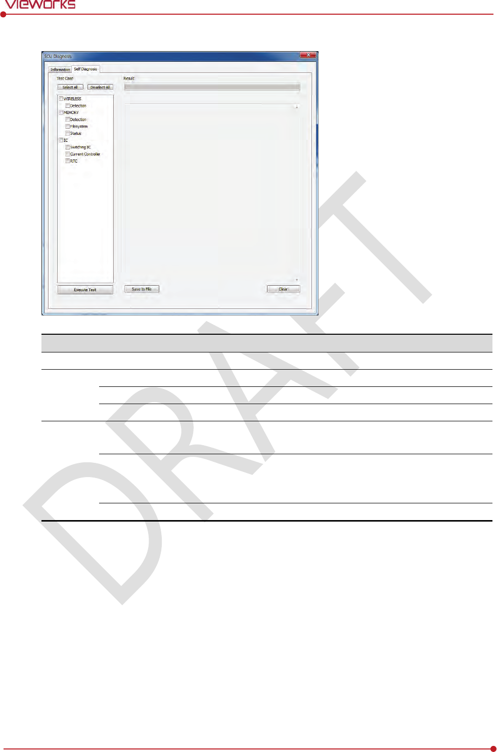
Rev.1.0
Page 123 of 151 VW40-152-009
VIVIX-S 1012N User Manual
Self-Diagnosis Items of SCU
Category
Item
Form
Expected problem
Action
Wireless
Detection
Decision
Defective wireless module
Contact a service eingineer.
Memory
Detection
Decision
Not available to save logs.
Contact a service eingineer
.
File System
Decision
Not available to save logs.
Contact a service eingineer
.
Status
Decision
N/A
N/A
IC
Switching IC
Decision
Not
available to connect the
detector and PC.
Contact a service eingineer
.
Current Controller
Decision
Not
available to block
overcurrent when using the
wired mode.
Contact a service eingineer
.
RTC
Decision
Errors in log acquisition time.
Contact a service eingineer
.
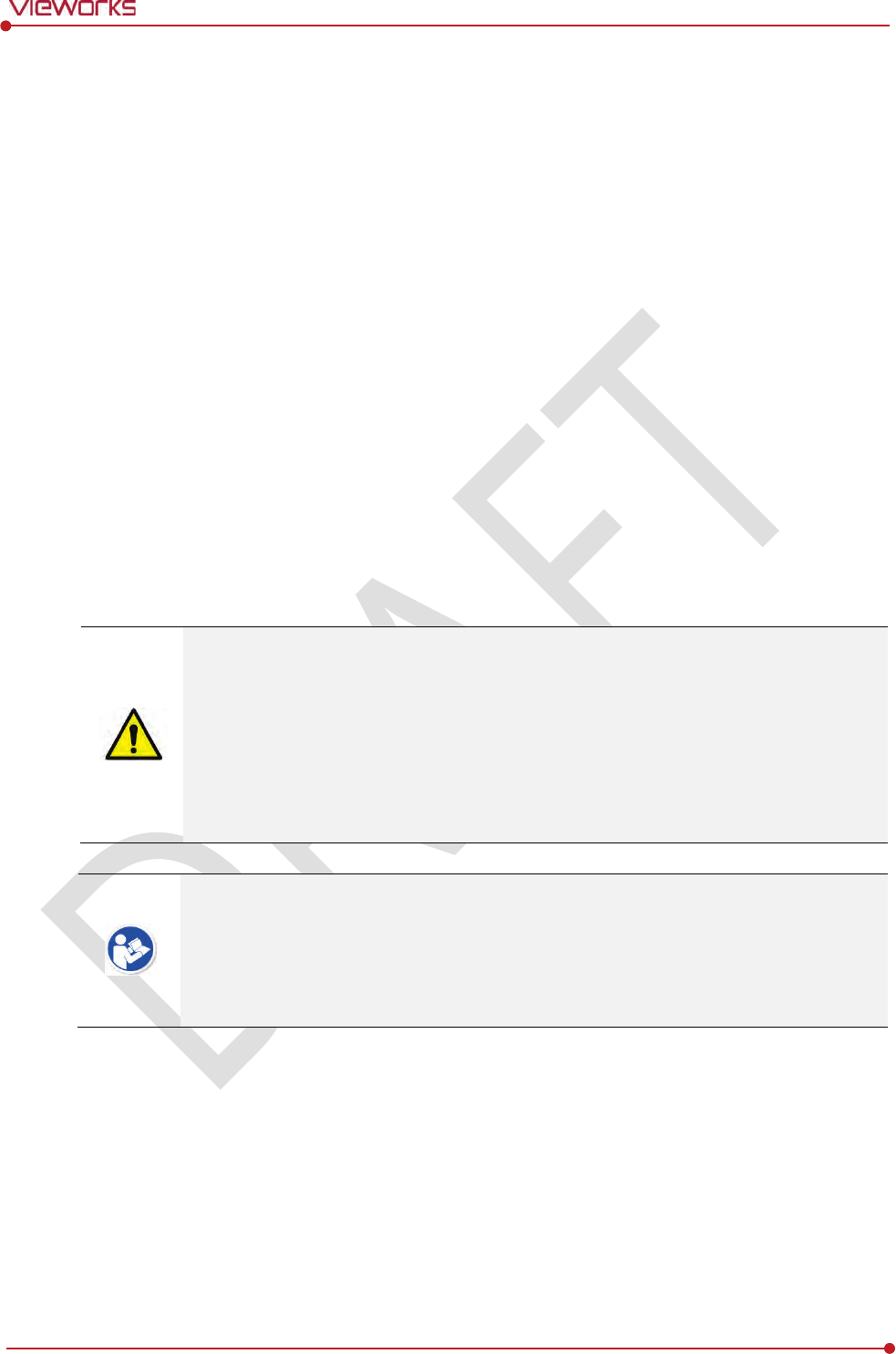
Rev.1.0
Page 124 of 151 VW40-152-009
VIVIX-S 1012N User Manual
7.3 Cleaning and Disinfection
After using the detector and peripheral equipments for examination, use germicidal disinfecting wipes or
cloth with mild diluted disinfectant detergent to clean surfaces of the product.
Recommended Detergent Foam
Recommended disinfectant wipe
Wip’ anios manufactured by Anios
Sani-cloth Active Wipes by PDI
Recommended disinfectant product
Sulfa’safe
Storage temperature: 5°C ~ 35°C
How to Use Detergent Foam
1 Prepare the disinfectant detergent and a clean and dry non-woven cloth.
2 Use the spray bottle to spray detergent to the cloth and clean the equipment.
3 After it has been cleaned, leave the equipment un-used for 15 minutes.
4 Conduct cleaning once a week or in case of contamination.
Do not re-use wipes.
Be careful to use disinfectant detergent which can cause irritation to eyes and skin.
Use in well-ventilated areas, and wear gloves at all times.
Do not clean the equipment with its power on.
Do not use abrasive brush and scraper to clean the product.
Be careful not to make liquid soak when cleaning battery bay and the connector on the
side of products.
Other Disinfectant detergent compliant to conditions listed below may be used following
proper procedures according to its own manual.
European Biocidal Products designed for surface disinfection (Directive 98/8/EC)
Detergent with composition of Didecyldimethylammonium chloride, polyhexamethylene
biguamide hydrochloride.

Rev.1.0
Page 125 of 151 VW40-152-009
VIVIX-S 1012N User Manual
7.4 Product Initialization
If the connection status of system is not stable or setting value is not correct, user can initialize the
products.
7.4.1 SCU Initialization
1 Click Configuration button of SCU after running the VIVIX Setup program.
2 Click Factory Reset button in Configuration dialogue.
3 Wait for SCU to be initialized and rebooted automatically.
4 Check whether SCU initialization is completed.
Default value of SCU initialization
Item
Default Value
Network
IP Address
169.254.
2.100
Subnet Mask
255.255.0.0
Gateway
169.254.
2.100
AP
AP On/Off
O
N
Frequency
5
㎓
Country
KR
Band
4
0㎒
Channel
+3
6
SSID
vivix
Key
1234567890
Test Mode
On/Off
Period
Trigger
Method
Packet
Polarity
Auto

Rev.1.0
Page 126 of 151 VW40-152-009
VIVIX-S 1012N User Manual
7.4.2 Detector Initialization
1 Click Configuration button of Detector after running the VIVIX Setup program.
2 Click Factory Reset button in Configuration dialogue.
3 Wait for Detector to be rebooted automatically.
4 Check whether detector initialization is completed.
Default value of detector initialization
Item
Default Value
Network
IP Address
169.254.
1.10
Subnet Mask
255.255.0.0
Gateway
169.254.
2.100
WNetwork
SSID
vivix
Key
1234567890
AP Scan
OFF
AP
AP On/Off
O
FF
Frequency
5
㎓
Country
KR
Band
4
0㎒
Channel
+3
6
SSID
vivix_ap
Key
1234567890
Test Pattern Type
20 sec.
Image Timeout Time
Disable
Power Management
Sleep
OFF
Sleep After
10 min.
Shut Down
OFF
Shut Down after
30 min.
Power Off
B
y Detector
Wireless Only
OFF

Rev.1.0
Page 127 of 151 VW40-152-009
VIVIX-S 1012N User Manual
7.4.3 Wireless Initialization of Detector
1 Turn off the detector.
2 Press and hold both the power button and AP button over 3 seconds.
3 Initialization will be conducted when orange LED is flickering, after that, the detector will be turned off
automatically.
4 Turn on the detector and check whether detector initialization is completed.
Default value of wireless initialization
Item
Default Value
Network
IP Address
169.254.
1.10
Subnet Mask
255.255.0.0
Gateway
169.254.
2.100
WNetwork
SSID
vivix
Key
1234567890
Wireless Only
OFF
AP
AP On/Off
O
FF
Frequency
5
㎓
Country
KR
Band
4
0㎒
Channel
+3
6
SSID
vivix_ap
Key
1234567890
When processing the wireless initialization of a detector, only the detector’s network
information is initialized as a default value.
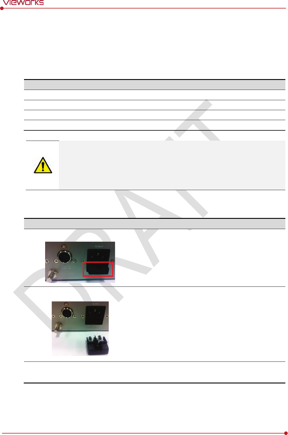
Rev.1.0
Page 128 of 151 VW40-152-009
VIVIX-S 1012N User Manual
7.5 Replacing the Fuse of SCU (SCU Basic only)
There are 2 fuses attached on the standard SCU for the purpose of electrical accident precaution, in case of
over current from external power input. Stop using the SCU immediately when the fuse is blown.
Fuse Information
Item
Specifications
Model
Litt
elfuse® 218002 (2EA)
Type
Time Lag Cartridge Fuse
Amp Rating
2A
Voltage Rating
250V
Pull the plug out and turn all the devices off before changing the fuse.
First, resolve the cause why the fuse is blown. Replace the fuse to the one provided as an
option (1 set / 2 ea) or to the one with same specifications when the fuse is out.
Be careful not to touch both the patient and the fuse holder at the same time or let the
patient touch the fuse holder.
How to Replace the Fuse
No.
Description
1
Separate the fuse from the holder located power input port on
the back side of standard SCU by pulling the fuse holder.
2
After checking, replace the fuse with correct specifications in
case
of need.
3
-
Insert the fuse holder again.

Rev.1.0
Page 129 of 151 VW40-152-009
VIVIX-S 1012N User Manual
8. Troubleshooting
This section gives information about troubleshooting.

Rev.1.0
Page 130 of 151 VW40-152-009
VIVIX-S 1012N User Manual
8.1 Trobleshooting
When you encounter problems while using the equipment, search for the table below for the problem or
error messages and try the solutions.If the problem persists, turn off the detector and consult your sales
representative or a distributor. Please refer to the details of the following symptoms or error messages.
Troubleshooting must be performed by service engineer who is authorized by Vieworks. If
an unqualified person performs troubleshooting on the system resulting in damaging the
detector, software or hardware, then the Vieworks or its representative is not responsible
for the detector repair regardless of remain
warranty. For more detailed information, refer
to <Warranty>.
8.1.1 Failed to Turn the Detector On
Symptom
Failed to turn on the power of the detector.
Expected Causes
Not installing battery pack well
Dead battery pack
Battery pack or Detector is broken down
Solutions
1 Install battery pack
2 Charge battery pack
3 Check the result after getting rid of the battery pack and connecting the tether cable.
4 Replace other battery packs and check the result of it.
5 Replace other Detectors and check the result of it.
6 Replace corresponding devices.
8.1.2 The Power Switch of SCU or Status LED is not worked
Symptom
The power switch of Basic SCU or SCU mini is not working.
The status LED of SCU is not responding.
Expected Causes
Power cable is broken down.
Errors in the fuse
Internal circuit is broken down.
Solutions
1 Check the connection between AC power cable and SCU Basic.

Rev.1.0
Page 131 of 151 VW40-152-009
VIVIX-S 1012N User Manual
2 Check the connection between DC power cable and SCU mini.
3 Turn off the power switch and turn on again and then check the fan or status of back side.
4 Replace another SCU and check the result of it
5 Replace the fuse of standard SCU. (refer to Change fuse of SCU)
6 Replace corresponding devices.
8.1.3 Communication Test is failed
Symptom
Transmission error is occurred, failure of communication test is occurred.
Expected Causes
Network connection problem
Network setting problem
PC environment setting problem
Wireless environment environment problem
Devices failure
Solutions
1 Check the connection of network cable between Workstation and SCU.
2 Check if the accurate network cable is used or not. (CAT 5E or 6)
3 Set the network information of Workstation, SCU and detector again.
4 Check whole workstation environment again such as firewall setting and release the power save mode.
5 Check surrounding wireless communication environment.
6 Boot up detector and SCU again by processing initialization. (Refer to <7.4 Product Initialization>.)
7 Replace other SCU and Detectors and check the result of it
8 Replace corresponding devices.
8.1.4 The Active LED and Data LED of the Detector are blinking
Symtom
The active LED and data LED is blinking when power LED is ON.
Expected Causes
Detector registeration error
Data transmission error
Solutions
1 Turn on SCU again
2 Check the network cable connection
3 Check the workstation environment and network information again
4 Check if the surrounding wireless communication is good
5 Check cable connection again when connected with tether interface cabel
6 Replace other devices and check the result of it

Rev.1.0
Page 132 of 151 VW40-152-009
VIVIX-S 1012N User Manual
7 Replace corresponding devices.
8.1.5 Errors in Detector LED
Symptom
All LED lamps of detector are blinking.
2 LED lamps of detector are blinking and remaining is blinking slowly.
Expected Causes
Internal hardware errors of the detector.
Solutions
1 Boot up the detector again and check the result of it
2 Replace the detector.
8.1.6 Rapid Consumption of Battery
Symptom
Consumption of fully charged battery pack is fast.
Expected Causes
Performance decrease caused by usage of long time.
Usage of battery pack in low temperature environment.
Solutions
1 Replace to new battery pack if the battery pack has been used for a long time. (Battery pack is
consumables)
2 Use battery pack in room temperature environment. Charging capacity of battery pack in low
temperature environment will be decreasing.
8.1.7 Battery Pack or Installation Part of Battery is Getting Hot
Symptom
Battery pack or compartment for installation of battery pack is getting hot.
Expected Causes
Battery pack failure
Detector Failure
Solutions
1 Do not use battery pack
2 Consult with service engineers of Vieworks.

Rev.1.0
Page 133 of 151 VW40-152-009
VIVIX-S 1012N User Manual
9. Regulatory Information
This section gives explanation about the regulatory information and standard related to the
products
Medical Equipment Safety Standards
Radio Frequency Compliance Information
Labels and Symbols
Guidance and Manufacturer Declaration for EMC

Rev.1.0
Page 134 of 151 VW40-152-009
VIVIX-S 1012N User Manual
9.1 Medical Equipment Safety Standards
9.1.1 Medical Equipment Classification
Item
Description
Type of
protection against electrical shock
Class Ⅰ
equipment Internally powered
Degree of protection against electrical shock
Type
B applied parts
Degree of protection against ingress of water
IPX
0
Operation mode
Continuous operation
Flammable anesthetic
s
NOT suitable for use in the presence of a flammable
a
nesthetic mixture with air or with oxygen or nitrous
o
xide.
9.1.2 Product Safety Standard
South Korea
전기, 기계적 안전성에 관한 시험: IEC 60601-1과 식품의약품안전청고시 제 2009-137호에 따른다.
전자파장해방지에 관한 시험: IEC 60601-1-2에 따른다.
전자파
간섭 (EMI)
전자파
전도
식품의약품안전청
고시 2009-54호 1종 A급 기기로서 별표 1의 5.1
식품의약품안전청
고시 2009-54호 별표 1의 전자파장해 (간섭)
전자파
방사
식품의약품안전청
고시 2009-54호 1종 A급 기기로서 별표 1의 5.2
식품의약품안전청
고시 2009-54호 별표 1의 전자파장해(간섭)
전자파
내성 (EMS)
정전기방전
(ESD) 시험
식품의약품안전청
고시 2009-54호 별표 2의 36.202/36.202.2/ KN61000-4-2
방사성
RF 전자기장 시험
식품의약품안전청
고시 2009-54호 별표 2의 36.202/36.202.3/ KN61000-4-3
전기적
빠른 과도현상 (EFT)
시험
고시
2009-54호 별표 2의 36.202/36.202.4/ KN61000-4-4
서지
(Surge) 시험
고시
2009-54호 별표 2의 36.202/36.202.5/KN61000-4-5
전도성
RF 전자기장 시험
식품의약품안전청
고시 2009-54호 별표 2의 36.202/36.202.6/ KN61000-4-6
전원주파수자기장
시험
고시
2009-54호 별표 2의 36.202/36.202.8/ KN61000-4-8
전원공급
입력선의 전압 강하
,
순간정전
및 전압변동 시험
식품의약품안전청
고시 2009-54호 별표 2의 36.202/36.202.7/KN61000-4-11
전원주파수
변동
IEC 60601
-1:2007(ed.3) 10.2.2 power supply 및 식품의약품안전청 고시
2009
-54호 별표 2의 36.202.14

Rev.1.0
Page 135 of 151 VW40-152-009
VIVIX-S 1012N User Manual
U.S.A / Canada
Item
IEC 60601
-1(ed.2 am1+ am2+ co1)
Medical electrical equipment
- Part1: General requirements for safety
UL 60601
-1(ed.2)
-
CSA
-C22.2 No. 601-1-M90 (R2006)
Medical electrical equipment
– Part 1: General
requirements for safety
(adopted amendment 2:1995
to IEC60601-1)
IEC 60601
-1-2: 2007 (ed.3)
Medical electrical equipment
-Part 1-2: Collateral standard:
Electromagnetic compatibility
IEC 60601
-1-4: 2000 (ed.1.1)
Medical electrical equipment
- Part 1-4: Collateral Standard:
Programmable electrical medical systems
IEC 62304:2006
Medical device software
-software life cycle processes
ISO 14971:2012
Medical Device
- Application of risk management to medical devices
European Union
Item
MDD
(Medical Device Directive)
93/42/EEC
as amended by 2007/47/EC
EN ISO 13485:
2012
Medical devices
– Quality Management systems – Requirements for
regulatory purposes
EN 60601
-1: 2007(ed.3)
Medical electrical equipment
- Part1: General requirements for safety
IEC 60601
-1-2: 2007(ed.3)
Medical electrical equipment
-Part 1-2: Collateral Standard :
Electromagnetic compatibility
-Requirements and tests
IEC 60601
-1-4: 2000(ed.1.1)
Medical electrical equipment
- Part 1-4: Collateral Standard :
Programmable electrical medical systems
IEC 62304:2006
Medical device software
-Software life cycle processes
ISO 14971: 2012
Medical device
– Application of risk management to medical devices.

Rev.1.0
Page 136 of 151 VW40-152-009
VIVIX-S 1012N User Manual
9.2 Radio Frequency Compliance Information
Country
Item
U.S.A
FCC Part 15.107 Subpart (b) / 15.109(g) Subpart B
FCC Part 15 Subpart E 15.407
FCC Part 15 Subpart C 15.247
European Union
ETSI EN 301 489-1 V1.8.1 (EMC)
ETSI EN 301 489-17 V2.1.1 (EMC)
EN 300 328 V.1.7.1; EN 301 893 V1.6.1 (RF)
EN 62311:2008 (RF Exposure)
ETSI EN 300 328 V1.7.1; EN 301 893, V1.5.1 (Radio Spectrum)
South Korea
Clause 3, Article 58-2 of Radio Waves Act
Clause 2, Article 58-2 of Radio Waves Act
Japan
Article 2-1-19, 2-1-19-3, 2-1-19-3-2 of the Radio law (MIC)
9.2.1 FCC Compliance
This equipment has been tested and found to comply with the limits for a Class B digital device,
pursuant to part 15 of FCC Rules. These limits are designed to provide reasonable protection against
harmful interference in a residential installation.
Operation is subject to the following tow conditions.
This device may not cause harmful interference.
This device must accept any interference received, including interference that may cause
undesired operation.
This equipment generates, uses, and can radiate radio frequency energy and, if not installed and used
in accordance with the instruction, may cause harmful interference to radio communications. However,
there is no guarantee that interference will not occur in a particular installation. If this equipment does
cause harmful interference to radio or television reception, which can be determined by turning the
equipment off and on, the user is encouraged to try to correct the interference by one or more of the
following measure.
Reorient or relocate the receiving antenna.
Increase the separation between the equipment and receiver.
Connect the equipment into an outlet on a circuit different from where the receiver is connected.
Consult the distributor or an experienced radio/TV technician for help.
Change or modification which is not expressly approved by the party responsible for
compliance could void the user’s authority to operate the equipment.
5.15-5.35G㎐ band is restricted to indoor operations only.
The SAR limit set by the FCC is 1.6 W/kg.
The highest SAR value for this model when tested for use at the front is 0.568 W/kg.
The front side of a detector should be used for image acquisition.

Rev.1.0
Page 137 of 151 VW40-152-009
VIVIX-S 1012N User Manual
9.2.2 FCC SAR
OET Bulletin 65, Supplement C (Edition 01-01)
9.2.3 CE R&TTE SAR
Item
EN 6
2311:2008
Assessment of electronic and electrical equipment related to human
exposure restrictions for electromagnetic fields
. (0 Hz - 300 GHz)
EN 62209
-1:2006
Human exposure to radio frequency fields from hand
-held and body-
mounted wireless communication
devices – Human models,
instrumentation, and procedures.
Part 1: Procedure to determine the specific absorption rate (SAR)
for hand-held devices used in close proximity to the ear
(frequency
range of 300 MHz to 3 GHz).
EN 62209
-2:2010
Human Exposure to R
adio Frequency Fields from Handheld and Body-
Mounted Wireless Communication Devices
– Human models,
Instrumentation, and Procedures.
Part 2:
Procedure to determine the specific absorption rate(SAR) for
mobile wireless communication devices used in close proximity to
the human body (frequency range of 300 MHz to 6 GHz).
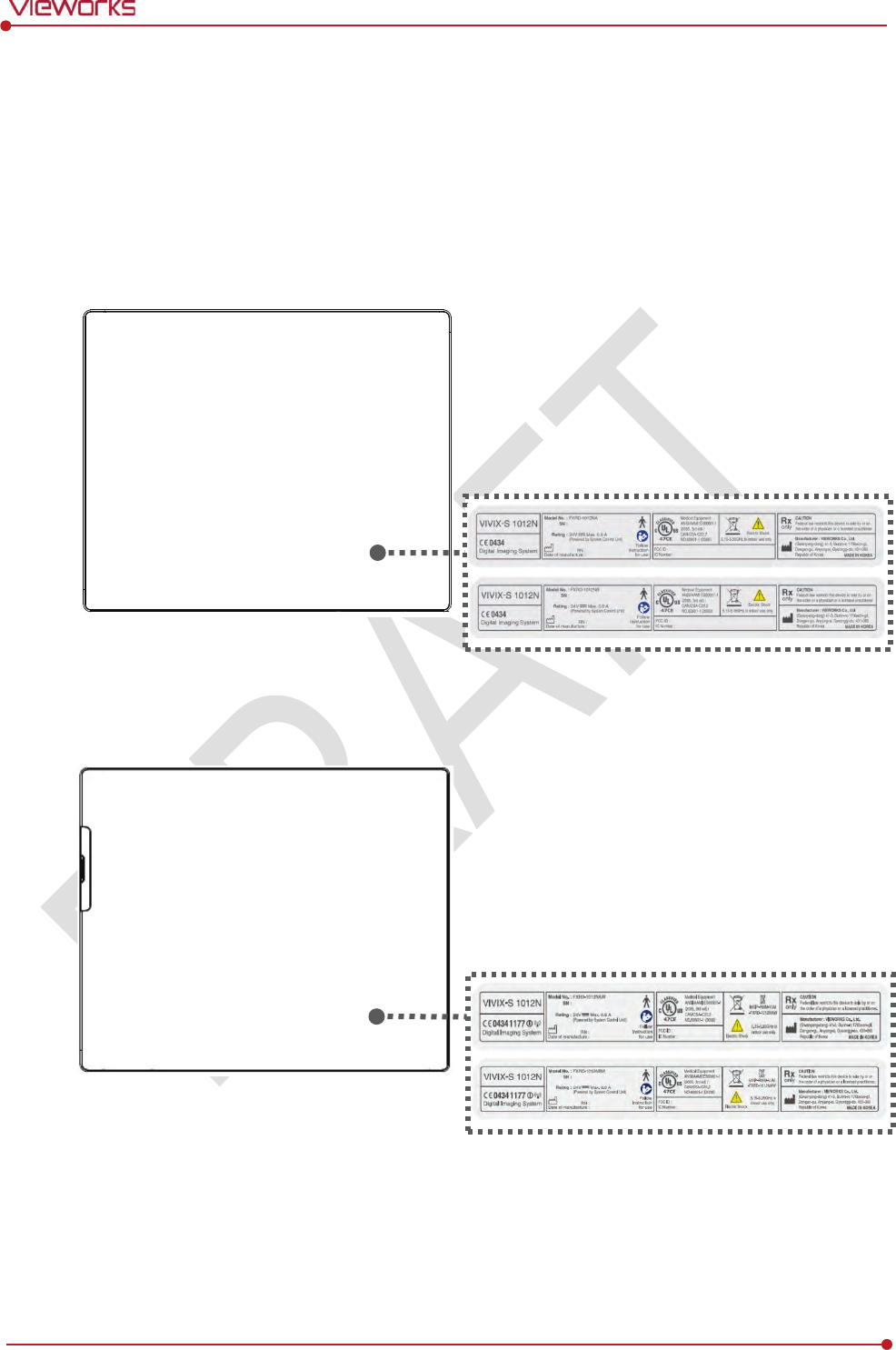
Rev.1.0
Page 138 of 151 VW40-152-009
VIVIX-S 1012N User Manual
9.3 Labels and Symbols
The ViVIX-S 1012N detector and relevant components have labels attached on them. The contents and
locations of each label are indicated below.
9.3.1 Label
VIVIX-S 1012NA / 1012NB (Wired Detector)
VIVIX-S 1012NAW / 1012NBW (Wireless Detector)
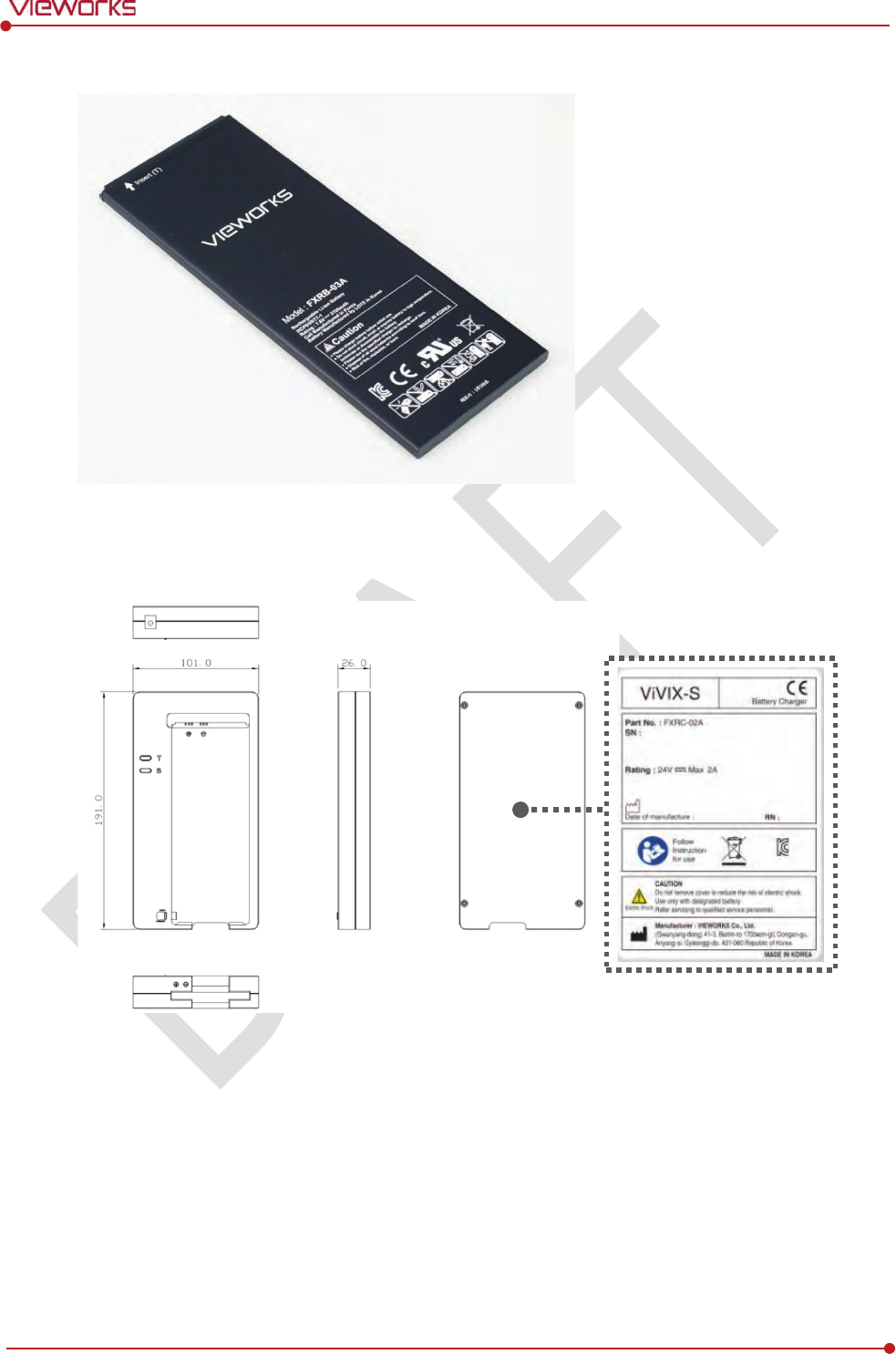
Rev.1.0
Page 139 of 151 VW40-152-009
VIVIX-S 1012N User Manual
Battery
Battery Charger
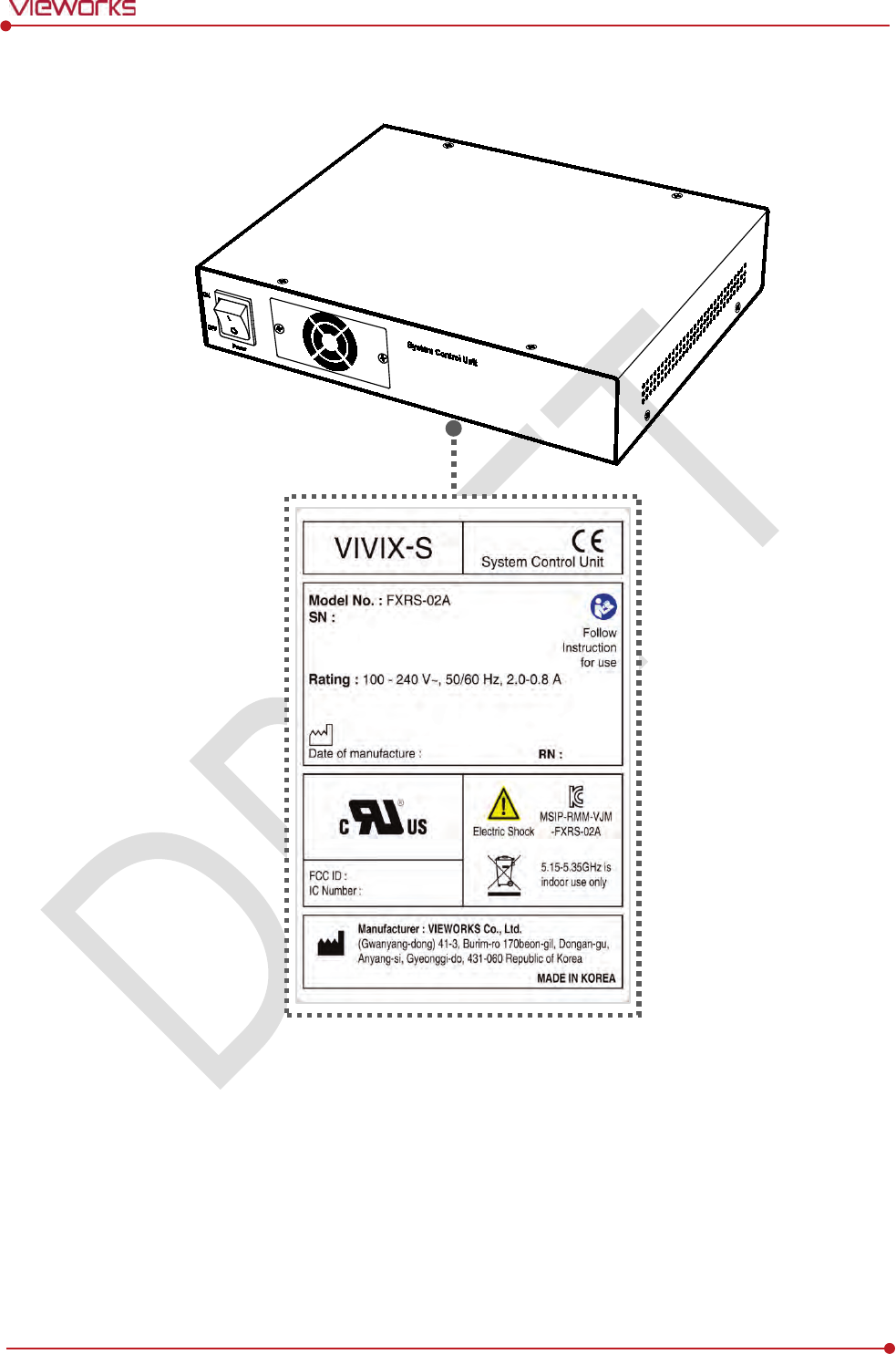
Rev.1.0
Page 140 of 151 VW40-152-009
VIVIX-S 1012N User Manual
SCU Basic (FXRS-02A)
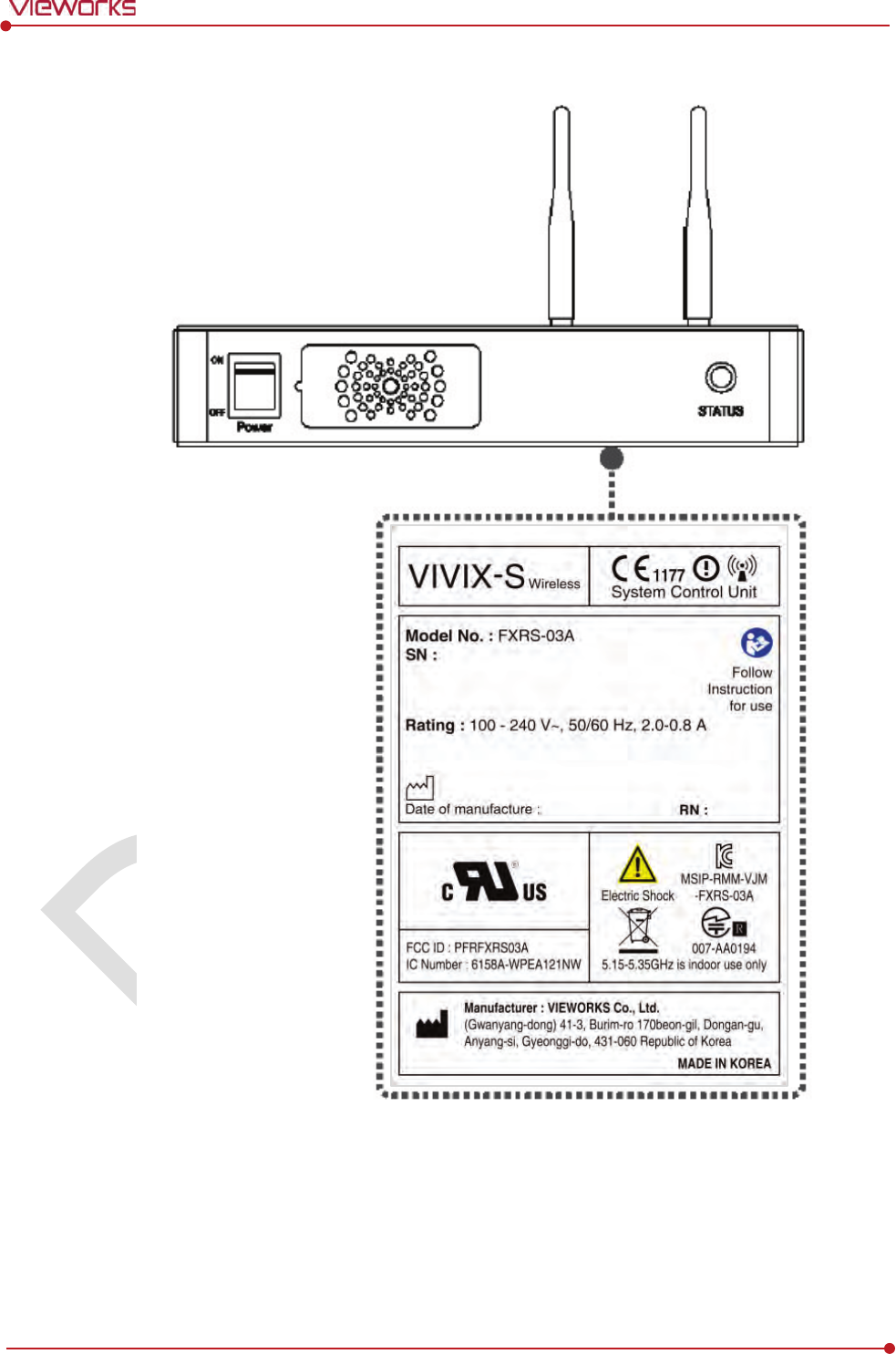
Rev.1.0
Page 141 of 151 VW40-152-009
VIVIX-S 1012N User Manual
SCU Basic (FXRS-03A)
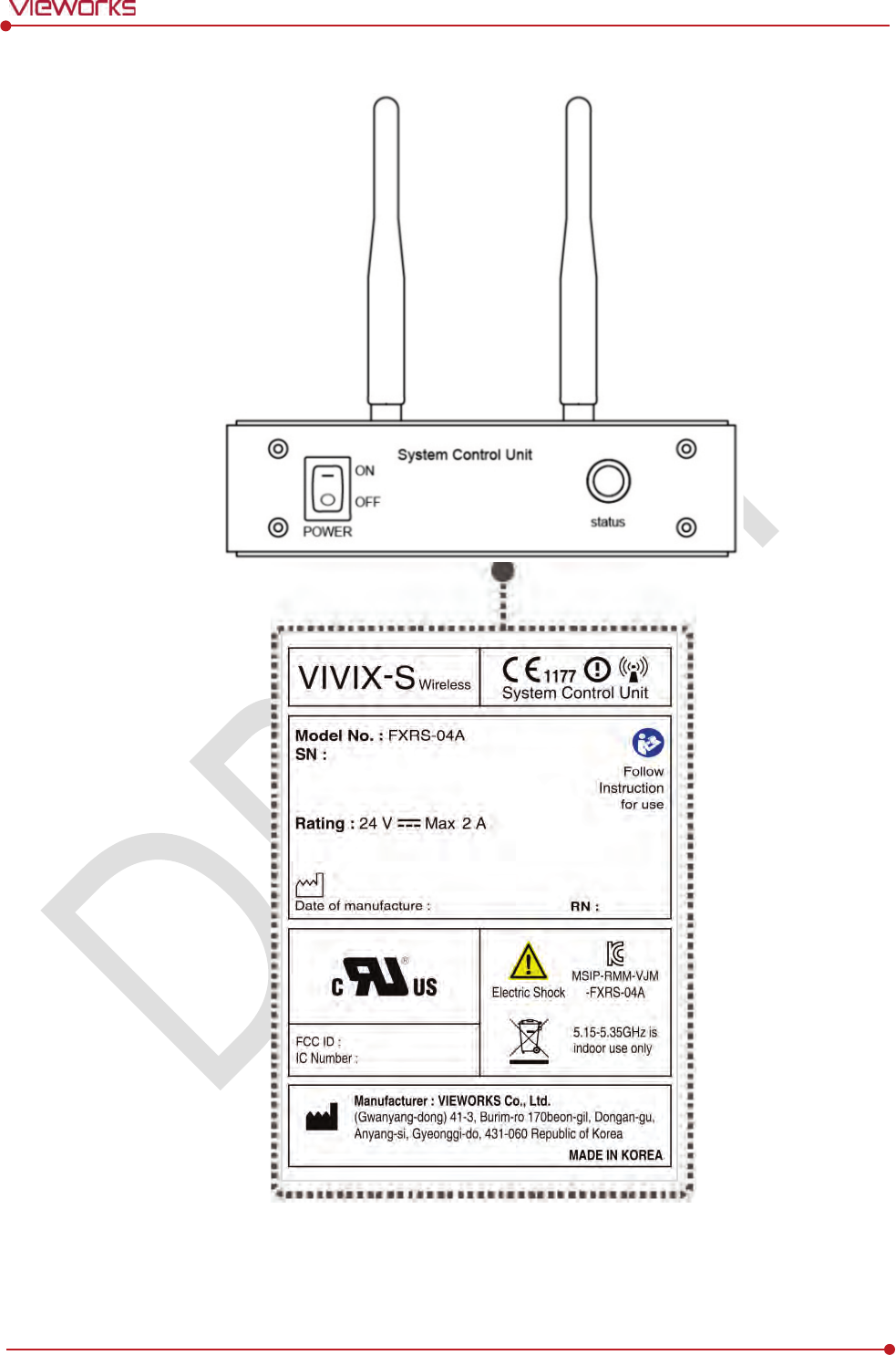
Rev.1.0
Page 142 of 151 VW40-152-009
VIVIX-S 1012N User Manual
SCU mini (FXRS-04A)
Rev.1.0
Page 143 of 151 VW40-152-009
VIVIX-S 1012N User Manual
Outer Box [TBD]
9.3.2 Product Serial Number
Serial Number Composition
The serial numbers for each product or accessory are composed as follows.
V 1 D A B J 0 0 1
Item Composition
Year Month Serial number
Revision will be updated in case of follows.
Mass production or a large amount of order.
Exterior alteration.
Item code will be produced based on internal management standard of vieworks.
Composition code is like follows.
D: Detector
S: SCU
C: Battery Charger
Range of Serial Number is 001 ~ 999.
Initial Per Year
11 12 13 14 15 16 17 18 19 20
AA AB AC AD AE AF AG AH AI BJ
Initial Per Month
1 2 3 4 5 6 7 8 9 10 11 12
A B C D E F U V W X Y Z
Composition of Serial Number for Each Item
Model
Composition
Serial Number
1
012NA
Detector
V
CDAEA001
1
012NB
Detector
V
DDAEA001
1012NAW
Detector
VADAEA001
1012NBW
Detector
VBDAEA001
FXRC
-02A
Battery Charger
V
ACAEA001
FXRS
-03A
SCU
Basic
VCSAEA001
FXRS
-04A
SCU
mini
V
ASAEA001
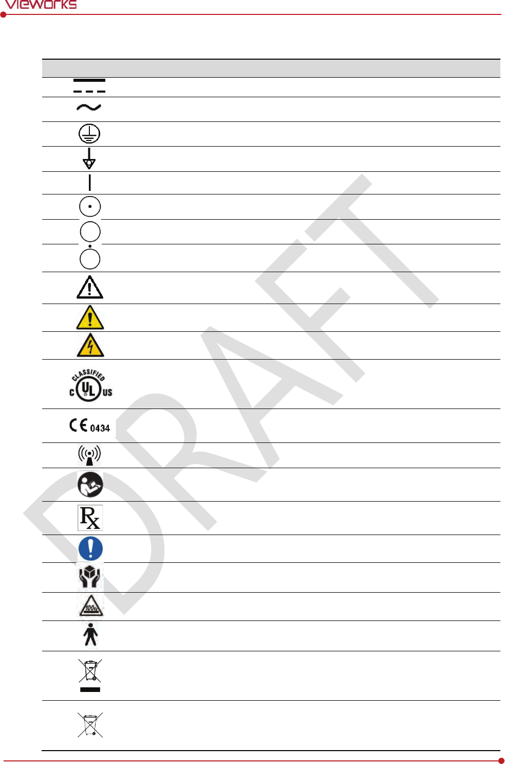
Rev.1.0
Page 144 of 151 VW40-152-009
VIVIX-S 1012N User Manual
9.3.3 Product Symbols
Symbol
Description
Direct current
A
lternating current
P
rotective earth (Ground)
Equipotentiality
Power
on
Power on for part of the
equipment
Power o
ff
Power off for part of the
equipment
A
ttention, consult accompanying documents
General warning sign
Warning sign for electricity
This Mark shows compliance with both Canadian and U.S. safety
requirements. With
Respect to electric shock, fire, and mechanical hazards only.
In accordance with
UL60601
-1 and CAN/CSA C22.2 No. 601.1.
This mark shows compliance of the
essential requirement and other relevant
provisions of Directive
93/42/EEC as amended by 2007/47/EC.
Non
-ionizing radiation
Read and understand all instructions and warning labels
in the product
documentation before using the equipment.
Keep manual for future reference.
Dealing with a medicine that can
only be given by a prescription from a doctor and
you should use a certain medication that a doctor recommended.
General
mandatory action sign
This mark indicates that this equipment must be handled with care
.
Do not jolt or apply excessive load to the equipment
.
T
his is a Type B Applied Part according to UL 60601-1 and EN 60601-1.
This mark indicates that the
equipment must be collected separately under the
Directive on Waste Electrical and Electronic Equipment 2002/96/EC (WEEE) in the
European Union. (For European Union)
This mark indicates that the battery must be collected separately under the Directive
o
n Waste Electrical and Electronic Equipment 2002/96/EC (WEEE) in the European
Union. (For European Union)

Rev.1.0
Page 145 of 151 VW40-152-009
VIVIX-S 1012N User Manual
9.4 Guidance and Manufacturer’s Declaration for EMC
This device has been tested for EMI/EMC compliance, but interference can still occur in an
electromagnetically noisy location. Attempt to maintain a suitable distance between electrical
devices to prevent malfunction.
9.4.1 Electromagnetic Emissions
The Equipment Under Test (EUT) is intended for use in the electromagnetic environment specified below.
The customer or user of the EUT should assure that it is used in such an environment.
Immunity test
Compliance
Electromagnetic
Environment
RF Emissions
(
CISPR 11)
Group 1
The EUT uses RF energy only for its internal function. Therefore, its
RF
emissions are very low and are not likely to cause any
interference in nearby electronic equipment
.
RF Emissions
(
CISPR 11)
Class B
The EUT is suitable for use in all establishments other than domestic
and those directly connected to the public low
-voltage power
supply network that
supplies buildings used for domestic purposes.
Harmonic emissions
(
IEC 61000-3-2)
Class A
Voltage fluctuations/
Flicker emissions
(
IEC 61000-3-3)
Complies
9.4.2 Electromagnetic Immunity
The ViVIX-S 1012N system is intended for using in the electromagnetic environment specified below. The
user of this system should assure that it is used in the following environment.
Electrostatic Discharge (ESD) IEC 61000-4-2
Item
Description
Immunity test
Electrostatic discharge (ESD) IEC 61000-4-2
IEC 60601
test condition
Contact ±6㎸
Air ±8㎸
Compliance Level
Contact ±6㎸
Air ±8㎸
Electromagnetic Environment
-
Guidance
Floors should be wood, concrete or ceramic tile.
If floors are covered with synthetic material, the relative humidity
should be at least 30%.

Rev.1.0
Page 146 of 151 VW40-152-009
VIVIX-S 1012N User Manual
Electrical Fast Transient/Burst IEC 61000-4-4
Item
Description
Immunity test
Electrical fast transient/burst IEC 61000-4-4
IEC 60601
test condition
Power supply lines ±2㎸
Input / output lines ±1㎸
Compliance
Level
Power supply lines ±2㎸
Input / output lines ±1㎸
Electromagnetic Environment
-
Guidance
Main power quality should be that of a typical commercial or hospital
environment.
Surge IEC 61000-4-5
Item
Description
Immunity test
Surge IEC 61000-4-5
IEC
60601 test condition
Differential mode ±1㎸
Common mode ±2㎸
Compliance Level
Differential mode ±1㎸
Common mode ±2㎸
Electromagnetic Environment
-
Guidance
Main power quality should be that of a typical commercial or hospital
environment.
Voltage Dips, Short Interruptions/Voltage Variations on Power Supply Input Lines IEC 61000-4-11
Item
Description
Immunity test
Voltage dips, short interruptions and voltage variations on power
supply input lines IEC 61000-4-11
IEC 60601
test condition
<5% Uт (>95% dip in Uт) for 0.5 cycle.
40% Uт (60% dip in Uт) for 5 cycles.
70% Uт (30% dip in Uт) for 25 cycles.
<5% Uт (<95% dip in Uт) for 5 sec.
Compliance Level
<5% Uт (>95% dip in Uт) for 0.5 cycle.
40% Uт (60% dip in Uт) for 5 cycles.
70% Uт (30% dip in Uт) for 25 cycles.
<5% Uт (<95% dip in Uт) for 5 sec.
Electromagnetic Environment
-
Guidance
Main power quality should be that of a typical commercial or hospital
environment.
If the user of the EUT image intensifier requires continued operation
during power mains interruptions, it is recommended that the EUT
image intensifier be powered from an uninterruptible power supply or
a battery.
Uт is the AC power prior to approving the test level voltage.
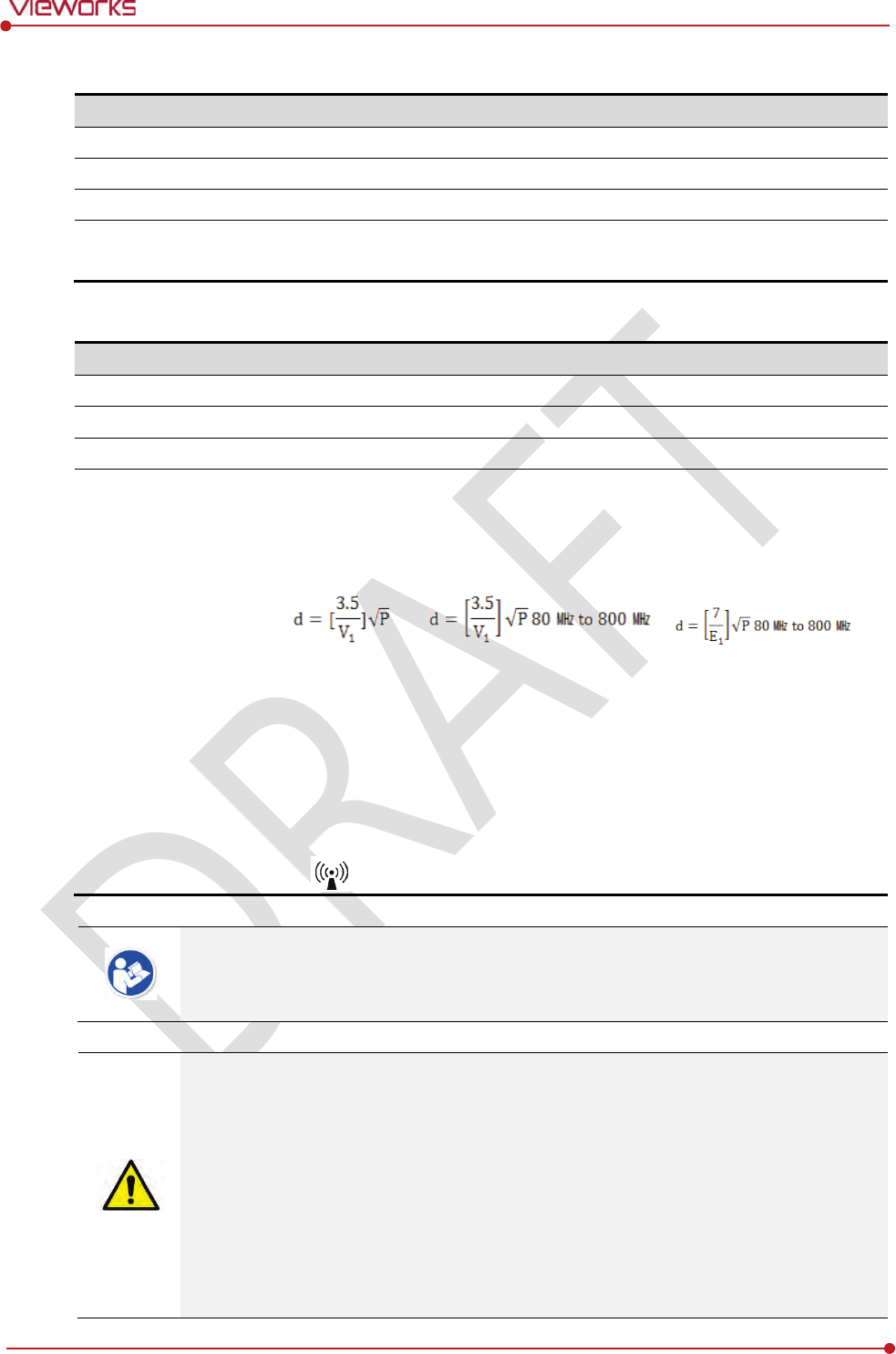
Rev.1.0
Page 147 of 151 VW40-152-009
VIVIX-S 1012N User Manual
Power Frequency (50/60 ㎐) Magnetic Field IEC 61000-4-8
Item
Description
Immunity test
Power frequency (50/60 ㎐) magnetic field IEC 61000-4-8
IEC 60601
test condition
3 A/m
Compliance Level
3 A/m
Electromagnetic Environment
-
Guidance
Power frequency magnetic fields should be at levels characteristic of a
typical location in a typical commercial or hospital environment.
Conducted RF IEC 61000-4-6 / Radiated RF IEC 61000-4-3
Item
Description
Immunity test
Conducted RF IEC 61000-4-6
Radiated RF IEC 61000-4-3
IEC 60601
test condition
3 Vrms 150 ㎑ to 80 ㎒
3 V/m 80 ㎒ to 2.5 ㎓
Compliance Level
3 Vrms 150 ㎑ to 80 ㎒
3 V/m 80 ㎒ to 2.5 ㎓
Electromagnetic
Environment
- Guidance
Portable and mobile RF communications equipment should be used no
closer to any part of the EUT, including cables, than the recommended
separation distance calculated from the below equations applicable to the
frequency of the transmitter.
P is the maximum output power rating of the transmitter in watts (W)
according to the transmitter manufacturer and d is the recommended
separation distance in meters (m).
Field strengths from fixed RF transmitters, as determined by an
electromagnetic site surveya, should be less than the compliance level in
each frequency range b.
Interference may occur in the vicinity of equipment marked with the symbol
.
At 80 ㎒ and 800 ㎒, the higher frequency range applies.
These guidelines may not apply in all situations. Electromagnetic propagation is affected
by absorption and reflection from structures, objects and people.
Field strengths from fixed transmitters, such as base stations for radio (cellular/cordless)
telephones and land mobile radios, amateur radio, AM and FM radio broadcast and TV
broadcast cannot be predicted theoretically with accuracy. To assess the electromagnetic
environment due to fixed RF transmitters, an electromagnetic site survey should be
considered. If the measured field strength in the location in which EUT is used exceeds
the applicable RF compliance level above, EUT should be observed to verify normal
operation. If abnormal performance is observed, additional measures may be necessary,
such as reorienting or relocating EUT.
Over the frequency range 150 ㎑ to 80 ㎒, field strengths should be less than [V1] V/m.

Rev.1.0
Page 148 of 151 VW40-152-009
VIVIX-S 1012N User Manual
10. Information
This section gives overview information for service and warranty of the product.
Service Information
Warranty
Revision History

Rev.1.0
Page 149 of 151 VW40-152-009
VIVIX-S 1012N User Manual
10.1 Service Information
10.1.1 Product Lifetime
The estimated product lifetime may be up to five (5) years under the appropriate regular inspection and
maintenance.
10.1.2 Regular Inspection and Maintenance
In order to ensure the safety of patients, operating personnel and third parties, and to maintain the
performance and reliability of the equipment, be sure to perform regular inspection at least once a year. If
necessary, clean up the equipment, make adjustments, or replace consumables.
There may be cases where overhaul is recommended depending on the conditions. Contact your sales
representative or distributor for regular inspections or maintenance.
10.1.3 Repair
If a problem cannot be solved even after taking the measures indicated in Troubleshooting and contact
your sales representative or a distributor for repairs. Please refer to the name label and provide the
following information.
Model name
FXRD-1012NA / FXRD-1012NB
FXRD-1012NAW / FXRD-1012NBW
Serial number
9 digit-number on the product label
Explanation of problem
Describe as detailed as possible.
10.1.4 Replacement Parts Support
Performance parts (parts required to maintain the functioning of the product) of this product will be
stocked for seven years after discontinuance of production, to allow for repair.
10.1.5 Consumables
The following consumable can deteriorate because of its characteristics and structure. For purchase of
consumables, contact your sales representative or distributor.
Battery pack: FXRB-03A

Rev.1.0
Page 150 of 151 VW40-152-009
VIVIX-S 1012N User Manual
10.2 Warranty
Vieworks warrants that this product will be free from defects in materials and workmanship for a period of
24 months from the date of delivery. If any such product proves defective during this warranty period,
Vieworks at its option, either will repair the defective product without charge for parts and labor, or will
provide a replacement in exchange for the defective product. In order to obtain service under this warranty,
Customer must notify Vieworks of the defect before the expiration of the warranty period and make
suitable arrangements for the performance of service. Customer shall be responsible for packaging and
shipping the defective product to the service center designated by Vieworks with shipping charges prepaid.
Vieworks shall pay for the return of the product to customer if the shipment is to a location within the
country in which Vieworks designated service center is located. Customer shall be responsible for paying all
shipping charges, duties, taxes, and any other charges for products returned to any other locations.
This warranty shall not apply to any defect, failure, or damage caused by improper or inadequate
maintenance and care. Vieworks shall not be obligated to furnish service under this warranty to repair
damage resulting from attempts by personnel other than Vieworks or its representatives to install, repair, or
service this product, to repair damage resulting from improper use or connection to incompatible
equipment or power source; or to service a product that has been modified or integrated with other
products when the effect of such modification or integration increases the time or difficulty of servicing the
product.
THIS WARRANTY IS GIVEN BY VIEWORKS WITH RESPECT TO THIS PRODUCT IN LIEU OF ANY OTHER
WARRANTIES, EXPRESS OR IMPLIED. VIEWORKS AND ITS VENDOR DISCLAIM ANY IMPLIED
WARRANTIES OF MERCHANTABLILITY OR FITNESS FOR A PARTICULAR PURPOSE. VIEWORKS
RESPONSIBILITY TO REPAIR OR REPLACE DEFECTIVE PRODUCTS IS THE SOLE REMEDY PROVIDED TO
THE CUSTOMER FOR BREACH OF THIS WARRANTY. VIEWORKS AND ITS VENDORS WILL NOT BE
LIABLE FOR ANY INDIRECT, SPECIAL, INCIDENTAL, OR CONSEQUENTIAL DAMAGES IRRESPECTIVE OF
WHETHER VIEWORKS OR THE VENDOR HAS ADVANCE NOTICE OF THE POSSIBILITY OF SUCH
DAMAGES.
There are no warranties which extend beyond the description mentioned in this document

Rev.1.0
Page 151 of 151 VW40-152-009
VIVIX-S 1012N User Manual
10.3 Revision History
Version
Date
Descriptions
1
.0
201
5-02-??
Initial Release
Vieworks Co., Ltd.
(Gwanyang-dong) 41-3, Burim-ro 170beon-gil, Dongan-gu, Anyang-si,
Gyeonggi-do, 431-060 Republic of Korea
Telephone: +82-70-7011-6161
Fax: +82-31-386-8631
Homepage: http://www.vieworks.com
European representative: DONGBANG ACUPRIME
1 Forrest Units, Hennock Road East, Marsh Barton, Exeter EX2 8RU, UK
Telephone: +44(0)-1392-829500
Homepage: http://www.acuprime.com