Vieworks FXRD-1717NAW Flat Panel Detector User Manual ViVIX S 1417W x
Vieworks Co., Ltd. Flat Panel Detector ViVIX S 1417W x
UserManual.wiki
>
Vieworks
>
FXRD-1717NAW User Manual
>
User Manual 1
Contents
1.
User Manual 1
2.
User Manual 2
User Manual 1
Navigation menu
Upload a User Manual
Namespaces
Wiki Guide
HTML
PDF
Info
Views
User Manual
Discussion / Help
Navigation

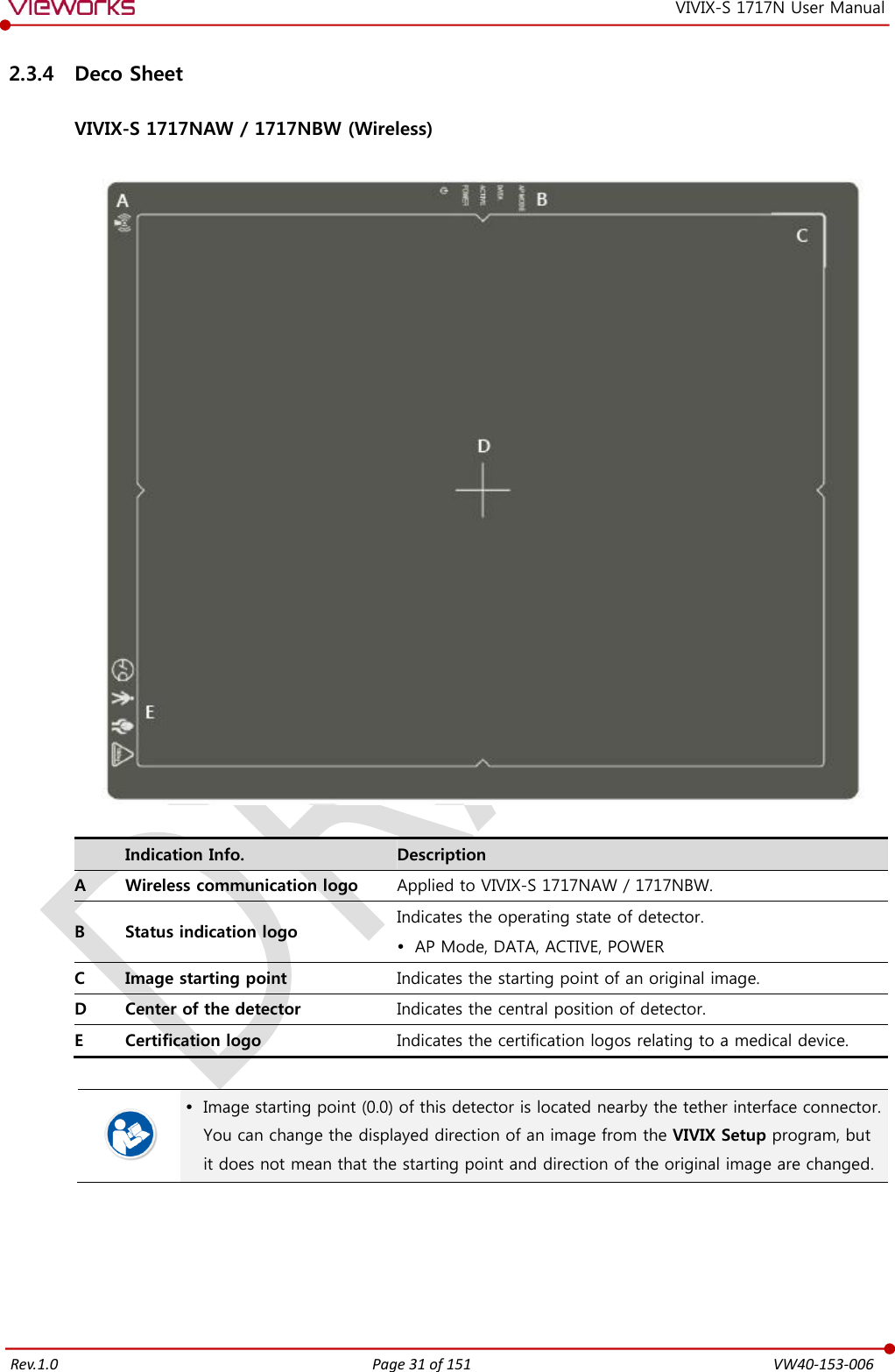
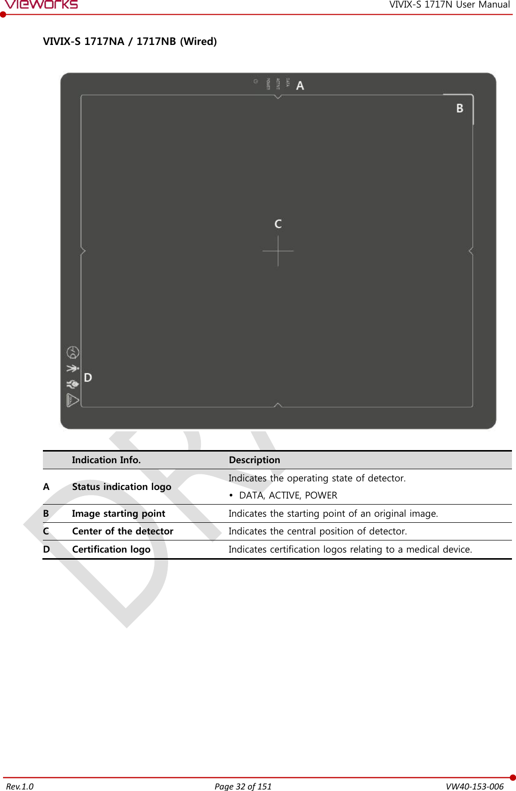
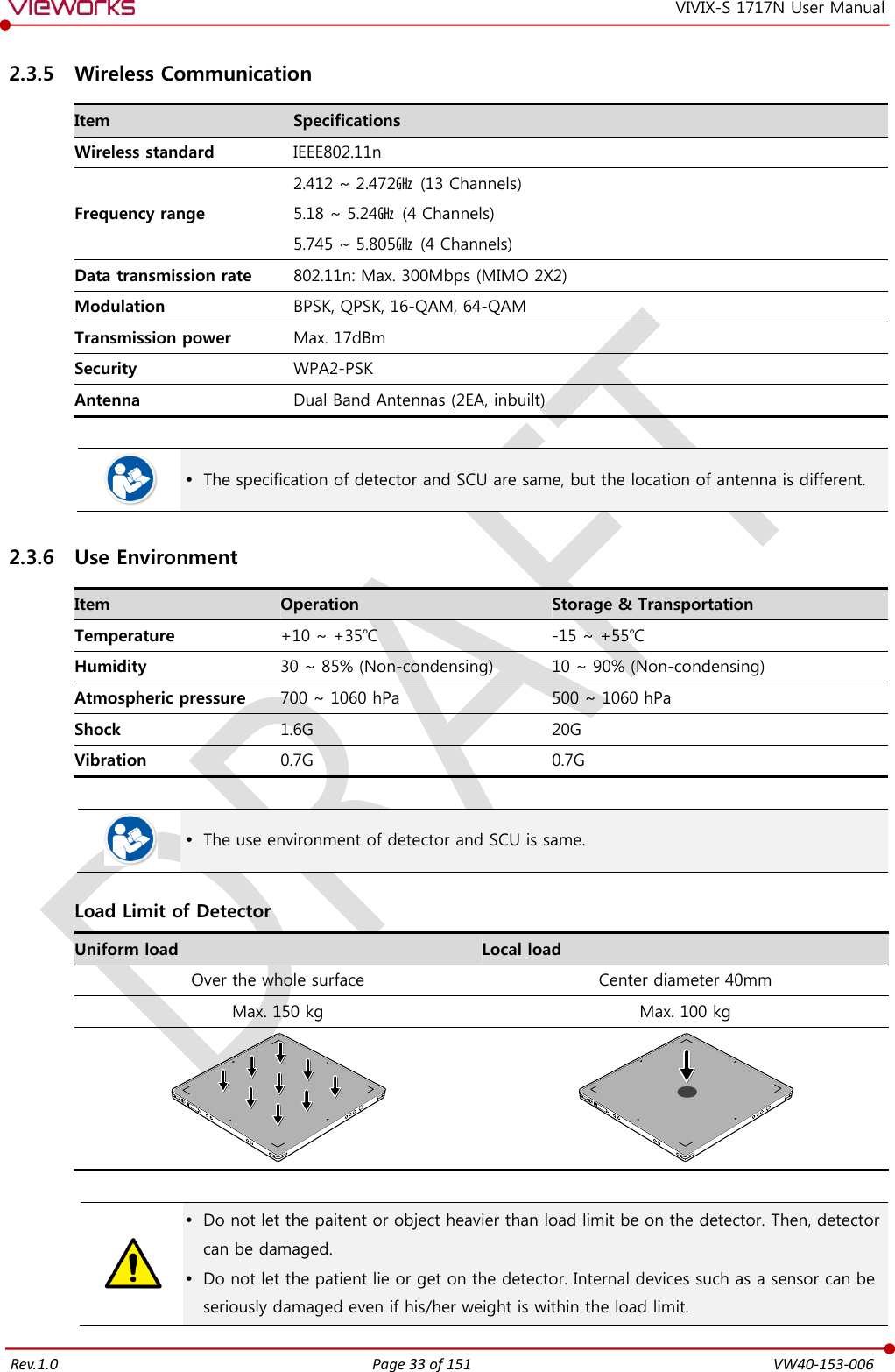
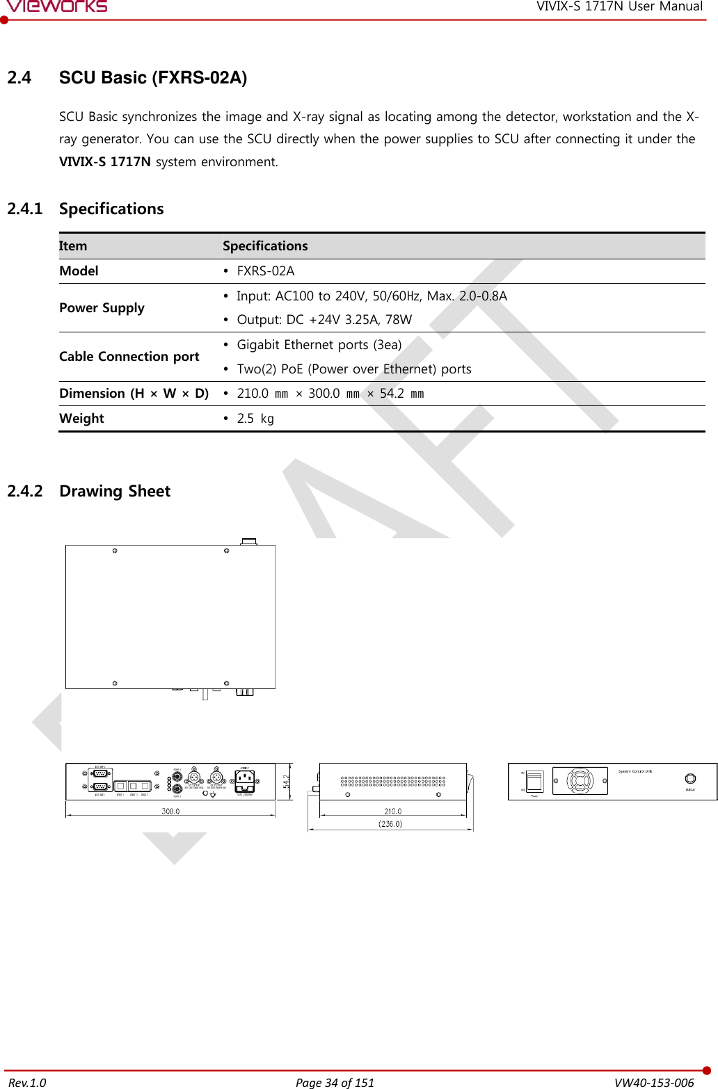
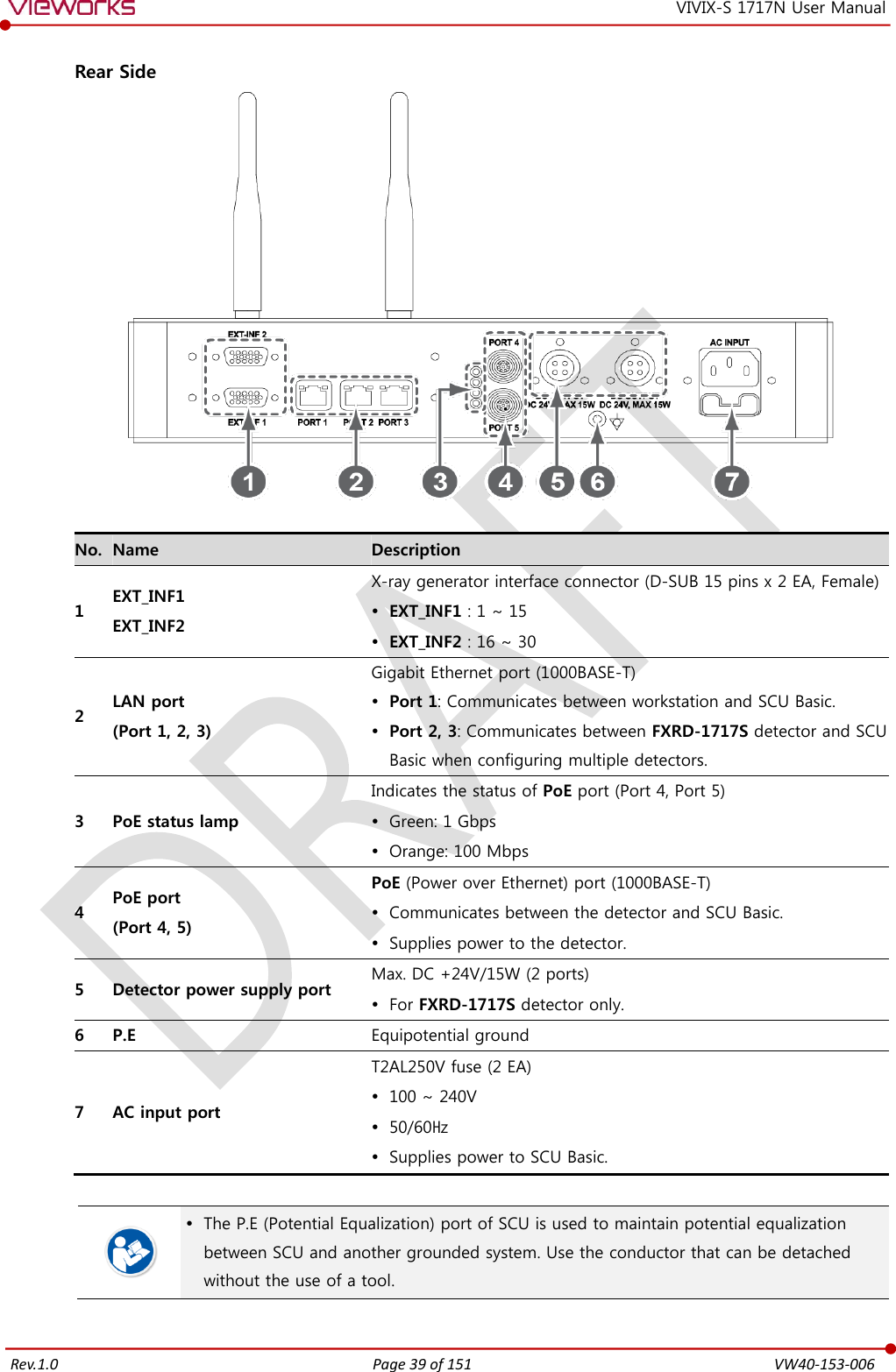
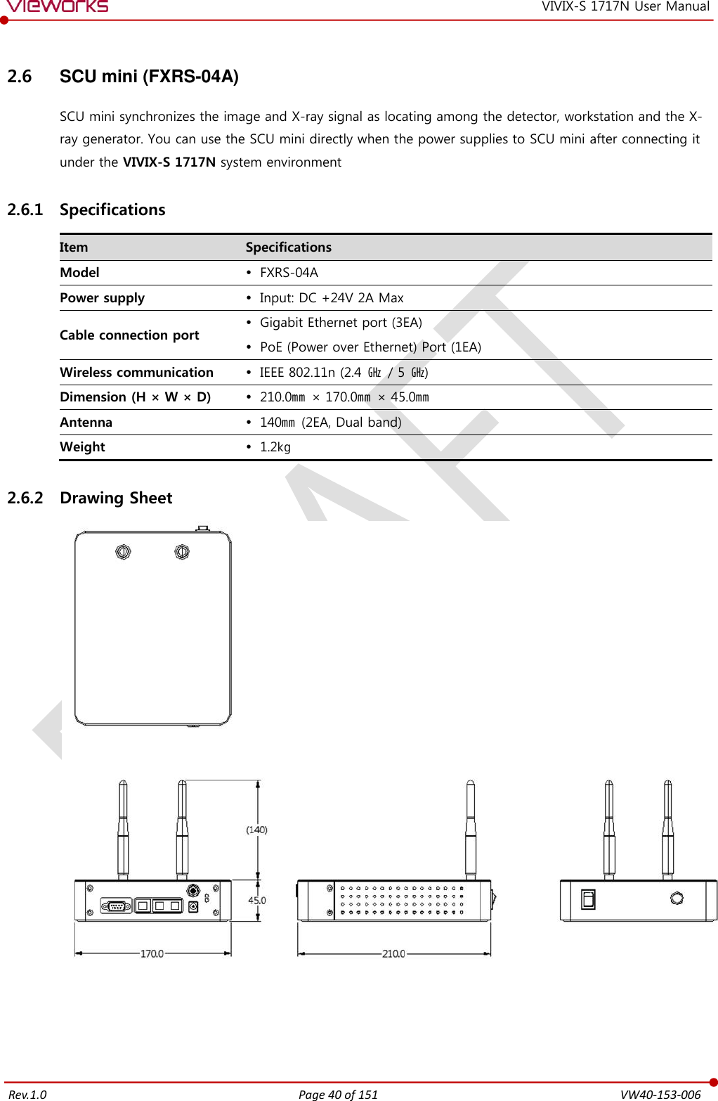
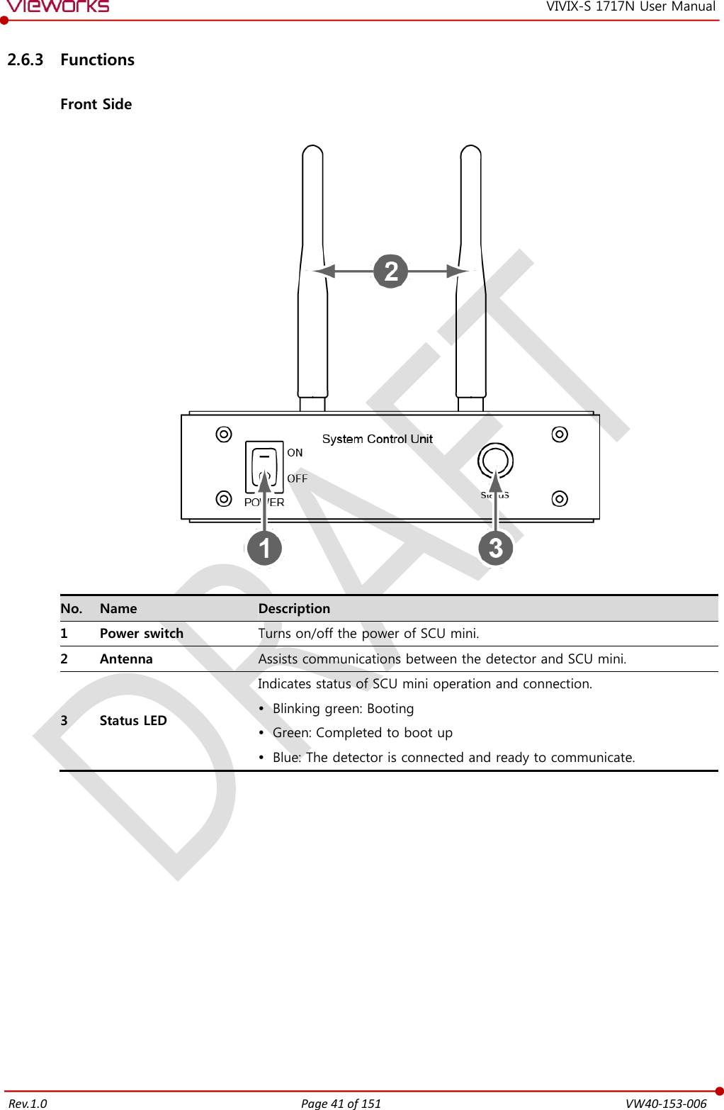
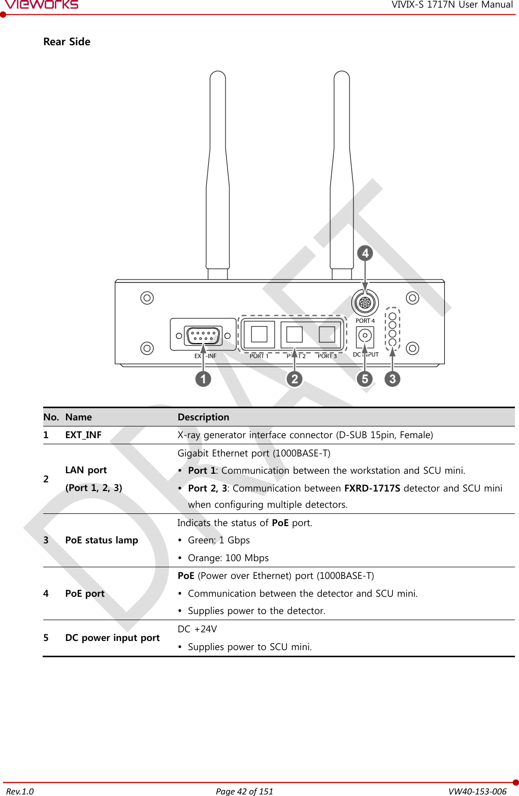
![Rev.1.0 Page 3 of 151 VW40-153-006 VIVIX-S 1717N User Manual 2.2.1 Detector............................................................................................................................................................................23 2.2.2 SCU (System Control Unit) ......................................................................................................................................23 2.2.3 Battery & Charger .......................................................................................................................................................24 2.2.4 Accessories ......................................................................................................................................................................25 2.3 VIVIX-S 1717N Detector ...................................................................................................................... 26 2.3.1 Specifications .................................................................................................................................................................26 2.3.2 Drawing Sheet ...............................................................................................................................................................27 2.3.3 Functions .........................................................................................................................................................................29 2.3.4 Deco Sheet .....................................................................................................................................................................31 2.3.5 Wireless Communication..........................................................................................................................................33 2.3.6 Use Environment ..........................................................................................................................................................33 2.4 SCU Basic (FXRS-02A) .......................................................................................................................... 34 2.4.1 Specifications .................................................................................................................................................................34 2.4.2 Drawing Sheet ...............................................................................................................................................................34 2.4.3 Functions .........................................................................................................................................................................35 2.5 SCU Basic (FXRS-03A) .......................................................................................................................... 37 2.5.1 Specifications .................................................................................................................................................................37 2.5.2 Drawing Sheet ...............................................................................................................................................................37 2.5.3 Functions .........................................................................................................................................................................38 2.6 SCU mini (FXRS-04A) ............................................................................................................................ 40 2.6.1 Specifications .................................................................................................................................................................40 2.6.2 Drawing Sheet ...............................................................................................................................................................40 2.6.3 Functions .........................................................................................................................................................................41 2.7 Battery Pack [TBD] ................................................................................................................................ 43 2.7.1 Specifications .................................................................................................................................................................43 2.7.2 Drawing Sheet ...............................................................................................................................................................43 2.8 Battery Charger ..................................................................................................................................... 44 2.8.1 Specifications .................................................................................................................................................................44 2.8.2 Drawing Sheet ...............................................................................................................................................................44 2.9 Others ...................................................................................................................................................... 45 2.9.1 X-ray Generator (Recommended Exposure Condition)..............................................................................45 2.9.2 Recommended Specifications of Workstation (PC) .....................................................................................45 2.9.3 Recommended Specifications of Grid ................................................................................................................45 3. System Configuration ................................................................................................................... 46 3.1 Detector Connection Methods ........................................................................................................... 47 3.1.1 Wireless Connection ...................................................................................................................................................47 3.1.2 Wired Connection ........................................................................................................................................................48](https://usermanual.wiki/Vieworks/FXRD-1717NAW.User-Manual-1/User-Guide-2601286-Page-3.png)