Vieworks FXRD-1717NAW Flat Panel Detector User Manual ViVIX S 1417W x
Vieworks Co., Ltd. Flat Panel Detector ViVIX S 1417W x
UserManual.wiki
>
Vieworks
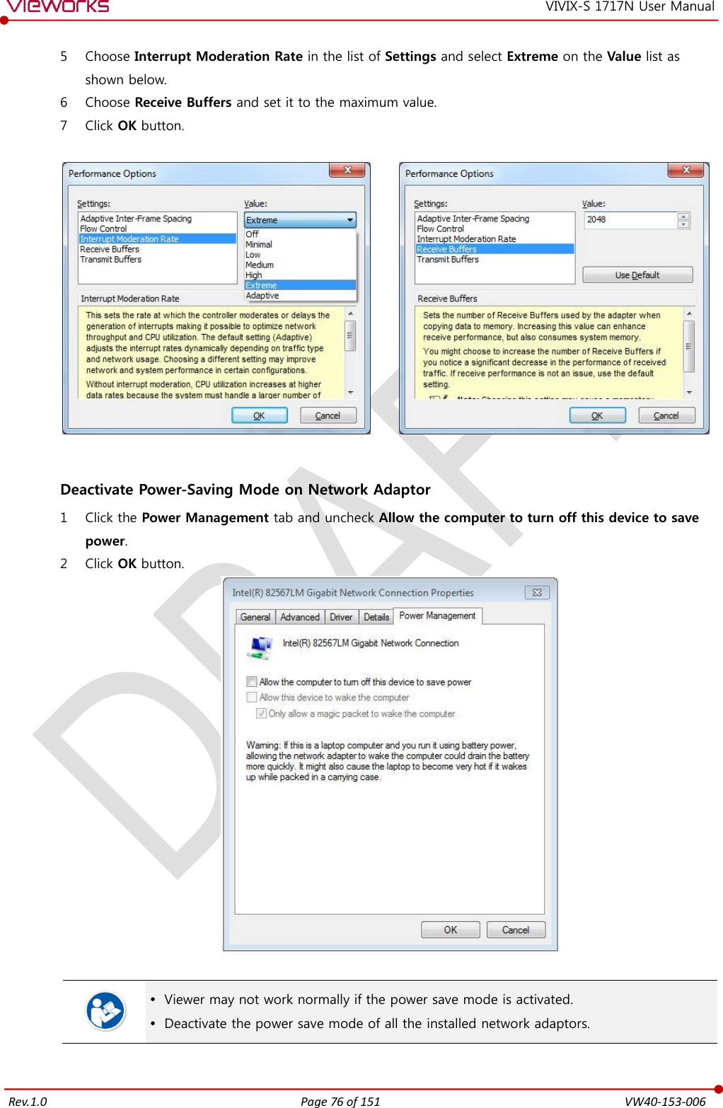
>
FXRD-1717NAW User Manual
>
User Manual 2
Contents
1.
User Manual 1
2.
User Manual 2
User Manual 2
Navigation menu
Upload a User Manual
Namespaces
Wiki Guide
HTML
PDF
Info
Views
User Manual
Discussion / Help
Navigation
![Rev.1.0 Page 80 of 151 VW40-153-006 VIVIX-S 1717N User Manual 5.1 Start Setting 5.1.1 Setup Program The VIVIX Setup program provides functions for setting and managing the internal data to make VIVIX-S 1717N wireless detector and SCU work normally. In addition, The VIVIX Setup program has diagnostic function for checking performance and abnormality of the devices as well as the image calibration function for improving the image quality. 5.1.2 Checking Devices Check information of the detector and SCU displayed on the Discovery list. [TBD] – Screen Shot Click Refresh Device List button to make the VIVIX Setup program search all detectors and SCU connected with the same network again. If devices are not displayed, check the power connection of the detector and click Refresh Device List button again. List Information List Description SCU Displays discovered list of SCU devices. Use Double-click the option to decide wether to use SCU or not. ‘V’ is displayed when it is able to be used. Discovery Displays whether SCU is found out or not. Detectors Displays discovered list of detectors. (Max. 4) ID ID of detector(sequence to distinguish registered detector) Line Trigger Selects a pin group when using Line Trigger. Discovery Displays whether the detector is discovered or not. Common Model No. Model name of SCU or detector Serial No. Serial number of SCU or detector IP Address IP Address of SCU or detector MAC Address MAC Address of SCU or detector](https://usermanual.wiki/Vieworks/FXRD-1717NAW.User-Manual-2/User-Guide-2601287-Page-10.png)
![Rev.1.0 Page 82 of 151 VW40-153-006 VIVIX-S 1717N User Manual 5.1.3 Getting into the Devices Click Next button to enter the registered SCU and detector. You can use SCU and the detector normally when the status of SCU is Connected and the Status of detector is Initialization OK. [TBD] – Screen Shot Button Button Description SCU Configuration Checks and sets information of SCU setting. Diagnosis Checks information of wireless AP on SCU and performs the self-diagnosis. Detector Configuration Checks and changes the information of detector settings. Calibration Checks and calibrates the detector calibration data. Image Checks and diagnoses the detector and acquired image. Diagnosis Checks the information of detector and tests the wireless transmission function as well as performs the self-diagnosis.](https://usermanual.wiki/Vieworks/FXRD-1717NAW.User-Manual-2/User-Guide-2601287-Page-12.png)
![Rev.1.0 Page 87 of 151 VW40-153-006 VIVIX-S 1717N User Manual 5.3 Detector Setting 5.3.1 Detector Configuration [TBD] – Screen Shot System Checks and sets system information of the detector. Item Description Model No Detector model name Serial No Detector serial numbers Package Version information of the detector firmware package Network Checks and sets network information of the detector. Item Description IP Address IP address of the detector Net Mask Subnet Mask of the detector Gateway Gateway of the detector WNetwork Sets AP (Access Point) information of wireless communication from the detector. Item Description SSID Configures wireless network ID AP from the detector. Key Configures wireless network key value of AP from the detector. Wireless Only Configures the wireless communication method of the detector. On The detector is operated in a wired way when a tether interface cable is connected. Off The detector is operated in a wireless way when a tether interface cable is not connected.](https://usermanual.wiki/Vieworks/FXRD-1717NAW.User-Manual-2/User-Guide-2601287-Page-17.png)
![Rev.1.0 Page 99 of 151 VW40-153-006 VIVIX-S 1717N User Manual 6.1.4 Gain Calibration Dialogue Vieworks provides the Gain data stored in the detector. However, you should download the data as the calibration cannot be performed in the detector automatically. [TBD] – Screen Shot Gain Calibration Item Description Target Value Shows the target value of Gain calibration. (Recommended : 8000 or higher) Current Value Shows value after the exposure when processing the manual Gain calibration. Stage Selects the number of manual Gain calibration and shows each calibration stage. Get Starts the manual Gain calibration. Cancel Cancels the manual Gain calibration. Load Gain Loads the Gain calibration data located in the Gain path. Upload Gain Uploads the Gain calibration data to the detector for using portable mode. Download Gain Downloads the Gain calibration data stored in the detector. Gain Path Shows the path of applied Gain data. This Gain data is provided in case the Gain calibration cannot be performed. You should do the Gain calibration in person as the detector condition can be different by the operating method or use environment.](https://usermanual.wiki/Vieworks/FXRD-1717NAW.User-Manual-2/User-Guide-2601287-Page-29.png)
![Rev.1.0 Page 100 of 151 VW40-153-006 VIVIX-S 1717N User Manual 6.2 Detector Configuration From the Detector Configuration dialog, you can configure the detector and check the images before or after doing calibration. [TBD] – Screen Shot Function List Item Description Detector Direction Compensation Sets the displayed direction of image. Effective Area Sets effective area of an image. Auto Offset Refresh Setting Sets conditions of automatic Offset Refresh. Time Interval (min.) Checks cycle of temperature change Temperature Interval (℃) Difference of over-temperature. Number of shot Number of Offset Refresh. Edge Masking (On / Off) Sets outside of the effective area to specific values. OSF Chooses whether to use OSF or not. Button Item Description Pan Moves an image to the desired location. Zoom Extends or constract an image. W/L Adjusts window level of an image. Fit Displays an image by adjusting it to the screen. E.A. Sets the effective area of an image with a mouse. ROI Sets the image area of interest. Effective Area On / Off Displays effective area of an image only. You can only change the displayed direction of an image from Detector Direction Compensation. The direction of an original image cannot be changed. Effective Area can be changed within the effective range which has been configured at the time of the first shipment of detector. Once Use offset refresh is used, the offset refresh is processed automatically as follows. Checks temperature difference of the detector between current temperature and the previous one at the time of offset refresh in every setting time from Time Interval. If the temperature difference is more than the one set in Temperature Interval, the offset refresh is carried out a number of times set in Number of shot.](https://usermanual.wiki/Vieworks/FXRD-1717NAW.User-Manual-2/User-Guide-2601287-Page-30.png)
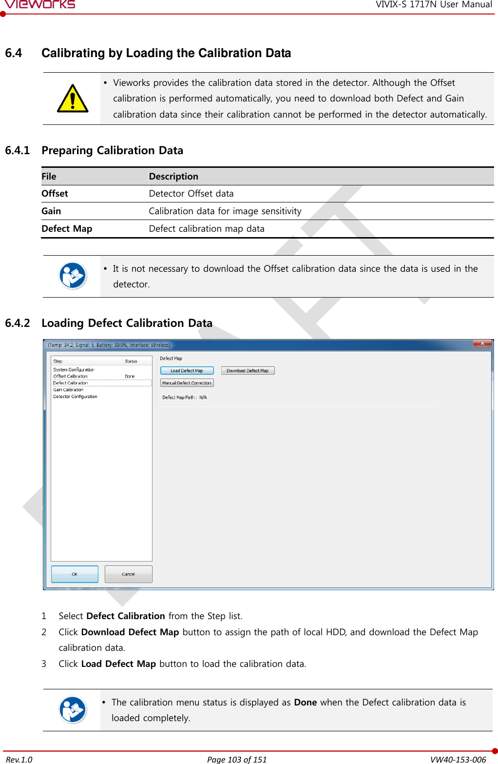
![Rev.1.0 Page 104 of 151 VW40-153-006 VIVIX-S 1717N User Manual Be sure to select the Defect Map data file provided with a detector. If the file has a wrong serial number or you select a wrong file, an error message will be displayed. Vieworks provides the Defect Map data stored in the detector. However, you should download the data as the calibration cannot be performed in the detector automatically. This Defect Map data has been generated through stringent test in the production stages of detector. However, new defect may be newly formed while using the detector. In this case, make sure to calibrate defects in person and generate a new defect map. 6.4.3 Loading Gain Calibration Data [TBD] – Screen Shot 1 Select Gain Calibration from the Step list. 2 Click Download Gain button to assign the path of local HDD. 3 Download the Gain calibration data by clicking Load Gain button. The calibration menu status is displayed as Done when the Gain calibration data is completed to be loaded. Be sure to select the Gain calibration data file provided with a detector. If the file has a wrong serial number or you select a wrong file, an error message will be displayed. Vieworks provides the Gain calibration data stored in the detector. However, you should download the data as the calibration cannot be performed in the detector automatically. This data is provided in case the Gain calibration cannot be performed. You should do the Gain calibration in person as the detector condition can be different by the operating method or use environment.](https://usermanual.wiki/Vieworks/FXRD-1717NAW.User-Manual-2/User-Guide-2601287-Page-34.png)
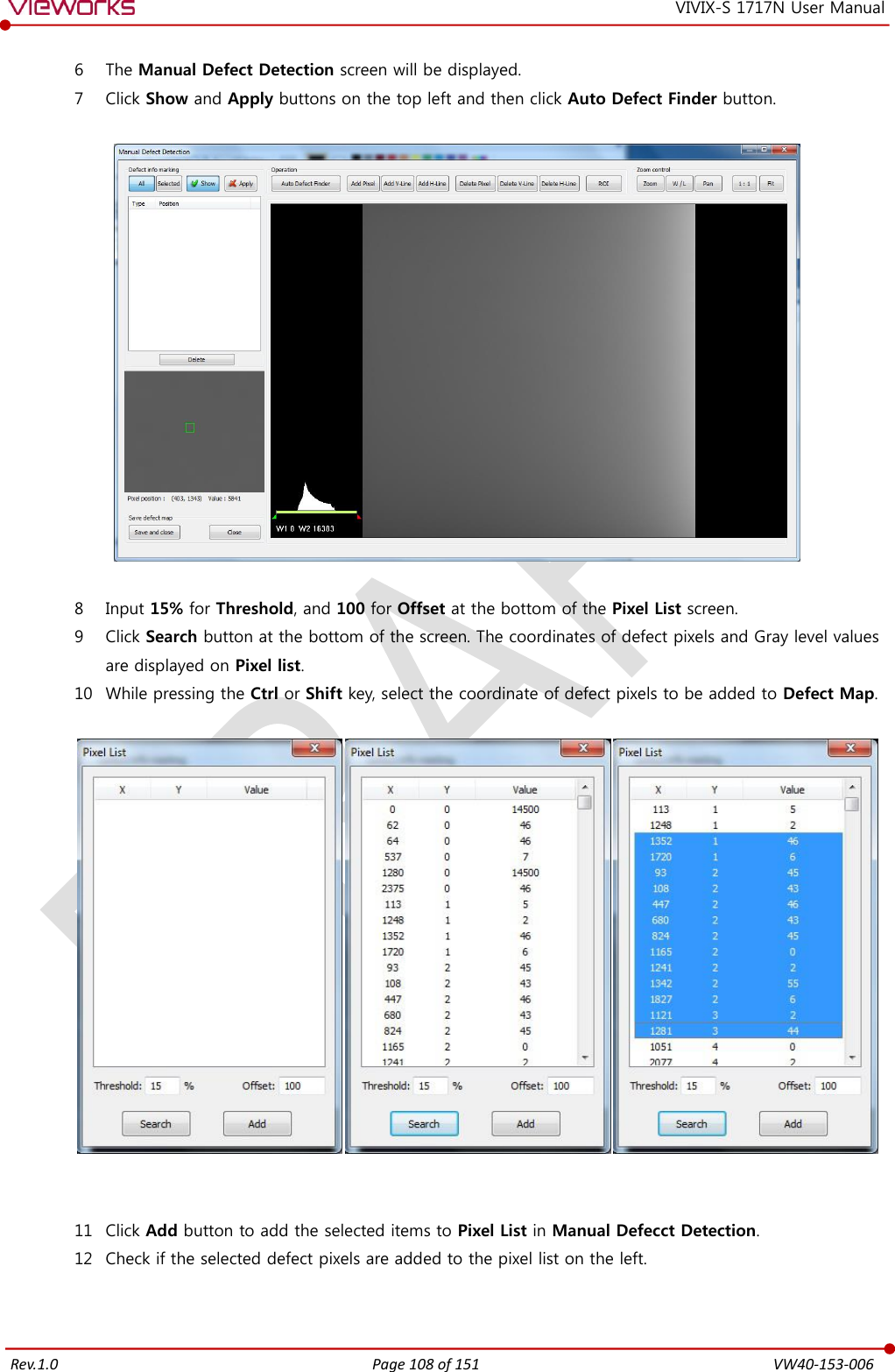
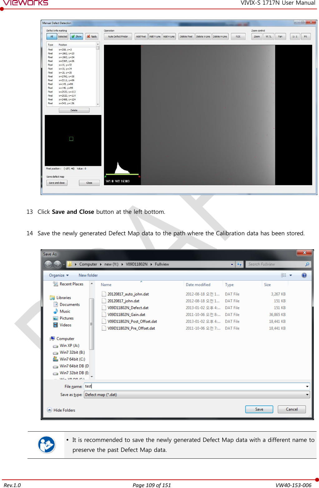
![Rev.1.0 Page 107 of 151 VW40-153-006 VIVIX-S 1717N User Manual 6.5.4 Auto Defect Correction While operating the detector, defect pixels may appear on the image. In this case, use the defect auto correction to calibrate the defect pixels. Be sure to check the followings before acquiring the FLAT image. Preheat the detector for 30 minutes or more. The recommend SID is 150 ㎝ (distance between X-ray tube and detector) Open the collimator of X-ray tube completely. Align the center of the detector with the center of collimator. Keep everything away from the detector surface. Adjust the x-ray dose to make the pixel value from 900 ~ 1100. Check if the calibration data (Offset, Defect Map, Gain) is registered normally. 1 Make an exposure of FLAT images from the Image dialog box. 2 Click Save Image button to save images to the user-defined folder. (saved as a raw file.) [TBD] – Screen Shot 3 Close the Image dialog box, and open the Calibration dialog box. 4 Choose Defect Calibration as follows and click Manual Defect Correction button. 5 Move to the folder where the raw file is saved and select the file. [TBD] – Screen Shot](https://usermanual.wiki/Vieworks/FXRD-1717NAW.User-Manual-2/User-Guide-2601287-Page-37.png)

![Rev.1.0 Page 114 of 151 VW40-153-006 VIVIX-S 1717N User Manual 7.1 Diagnosis 7.1.1 Image Diagnosis Check the image quality through Diagnosis tools after installing the detector or before usage. If the problems with regard to products or image occur during diagnosis, try to do a calibration again. If the problems are not solved, consult the sales representative in Vieworks or a service engineer. You can acquire and review an image from the Image window in VIVIX Setup program. You can review images by acquiring them through real exposure or getting Dark image by clicking Get Normal Image button. The number of images, pixel value and ROI value will be displayed. The effective area or whole area of an image can be checked. It is also available to check the image by changing its direction. Save the reviewed image as a raw one to analyze. You can acquire an image either applying Offset / Gain data or not. [TBD] – Screen Shot Diagnostic Functions Item Description Pan Press and drag a mouse button to move the image to the desired position. Zoom Press and hold a mouse button to move the image upwards or downwards for expanding / reducing the image. W/L Press and hold a mouse button to move the image to up/down/right/left for adjusting its window level. This function can be used without clicking W/L button, but with the right mouse button basically. Fit Sets the image to the center, which was moved by using Pan function. Statistic Clicks and drags the left mouse button to set arbitrary area. The coordinate, min/max value, average and standard deviations are displayed on Pickup ROI at the left side of image. ROI Clicks and drags the left mouse button to set window level automatically on a basis of min/max value of the configured area. Zoom Expands the image X1 2 times X2 4 times X4 16 times Offset Applicability of Offset data](https://usermanual.wiki/Vieworks/FXRD-1717NAW.User-Manual-2/User-Guide-2601287-Page-44.png)


![Rev.1.0 Page 143 of 151 VW40-153-006 VIVIX-S 1717N User Manual Outer Box [TBD] 9.3.2 Product Serial Number Serial Number Composition The serial numbers for each product or accessory are composed as follows. V 1 D A B J 0 0 1 Item Composition Year Month Serial number Revision will be updated in case of follows. Mass production or a large amount of order. Exterior alteration. Item code will be produced based on internal management standard of vieworks. Composition code is like follows. D: Detector S: SCU C: Battery Charger Range of Serial Number is 001 ~ 999. Initial Per Year 11 12 13 14 15 16 17 18 19 20 AA AB AC AD AE AF AG AH AI BJ Initial Per Month 1 2 3 4 5 6 7 8 9 10 11 12 A B C D E F U V W X Y Z Composition of Serial Number for Each Item Model Composition Serial Number 1717NA Detector VMDAEA001 1717NB Detector VNDAEA001 1717NAW Detector VODAEA001 1717NBW Detector VPDAEA001 FXRC-02A Battery Charger VACAEA001 FXRS-02A SCU V3SAEA001 FXRS-03A SCU Basic VCSAEA001 FXRS-04A SCU mini VASAEA001](https://usermanual.wiki/Vieworks/FXRD-1717NAW.User-Manual-2/User-Guide-2601287-Page-73.png)
![Rev.1.0 Page 147 of 151 VW40-153-006 VIVIX-S 1717N User Manual Power Frequency (50/60 ㎐) Magnetic Field IEC 61000-4-8 Item Description Immunity test Power frequency (50/60 ㎐) magnetic field IEC 61000-4-8 IEC 60601 test condition 3 A/m Compliance Level 3 A/m Electromagnetic Environment - Guidance Power frequency magnetic fields should be at levels characteristic of a typical location in a typical commercial or hospital environment. Conducted RF IEC 61000-4-6 / Radiated RF IEC 61000-4-3 Item Description Immunity test Conducted RF IEC 61000-4-6 Radiated RF IEC 61000-4-3 IEC 60601 test condition 3 Vrms 150 ㎑ to 80 ㎒ 3 V/m 80 ㎒ to 2.5 ㎓ Compliance Level 3 Vrms 150 ㎑ to 80 ㎒ 3 V/m 80 ㎒ to 2.5 ㎓ Electromagnetic Environment - Guidance Portable and mobile RF communications equipment should be used no closer to any part of the EUT, including cables, than the recommended separation distance calculated from the below equations applicable to the frequency of the transmitter. P is the maximum output power rating of the transmitter in watts (W) according to the transmitter manufacturer and d is the recommended separation distance in meters (m). Field strengths from fixed RF transmitters, as determined by an electromagnetic site surveya, should be less than the compliance level in each frequency range b. Interference may occur in the vicinity of equipment marked with the symbol. At 80 ㎒ and 800 ㎒, the higher frequency range applies. These guidelines may not apply in all situations. Electromagnetic propagation is affected by absorption and reflection from structures, objects and people. Field strengths from fixed transmitters, such as base stations for radio (cellular/cordless) telephones and land mobile radios, amateur radio, AM and FM radio broadcast and TV broadcast cannot be predicted theoretically with accuracy. To assess the electromagnetic environment due to fixed RF transmitters, an electromagnetic site survey should be considered. If the measured field strength in the location in which EUT is used exceeds the applicable RF compliance level above, EUT should be observed to verify normal operation. If abnormal performance is observed, additional measures may be necessary, such as reorienting or relocating EUT. Over the frequency range 150 ㎑ to 80 ㎒, field strengths should be less than [V1] V/m.](https://usermanual.wiki/Vieworks/FXRD-1717NAW.User-Manual-2/User-Guide-2601287-Page-77.png)