Vieworks FXRD-1717NAW Flat Panel Detector User Manual ViVIX S 1417W x
Vieworks Co., Ltd. Flat Panel Detector ViVIX S 1417W x
Vieworks >
Contents
- 1. User Manual 1
- 2. User Manual 2
User Manual 2

Rev.1.0
Page 71 of 151 VW40-153-006
VIVIX-S 1717N User Manual
4.2.4 Checking Status LED of Detector
Power LED
The power LED indicates the power status information which is permitted to the detector in green.
The power LED lights up when the power is permitted normally.
If the detector is connected with a tether interface, the power LED lights up when power is permitted
to SCU because the detector is supplied power from SCU.
Active LED
The active LED indicates status information about the possibility that the detector can be used
normally or not in orange.
The active LED is blinking when the detector is completed to boot up normally.
The Power LED is blinking when the detector turns to sleep mode.
The active LED is blinking when the wireless communication is being initialized.
Data LED
The data LED indicates status information of data processing in blue.
The data LED lights up when the detector is available to make data communication.
The data LED is blinking while the detector transmits or saves data.
Detector AP LED
The AP LED lights up in blue when the detector AP is on.
The AP LED is blinking in blue when the detector switches the AP status.
The AP LED is blinking in orange while the detector is synchronizing the wireless settings.
The communication status of detector is indicated when the detector AP is off.
Wirelss communication: Green LED at the 3rd level or higher / Orange LED under 2nd level.
Wired communication: Green LED in case of 1Gbps / Orange LED in case of 100Mbps connection.
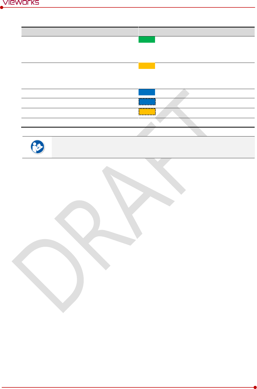
Summary List of Detector Status LED
Information
Power LED
Status LED
Data LED
In process of booting after the power
permission
Blink
OFF
OFF
Booting completed (Abnormal)
ON
-
-
Booting completed (Normal)
ON
ON
OFF
Ready for communication
ON
ON
ON
Sleep Mode
ON
Blink
OFF
In process of wireless initialization
ON
Blink
OFF
Data Communication (Send or Store)
ON
ON
Blink
Power OFF
OFF
OFF
OFF
Rev.1.0
Page 72 of 151 VW40-153-006
VIVIX-S 1717N User Manual
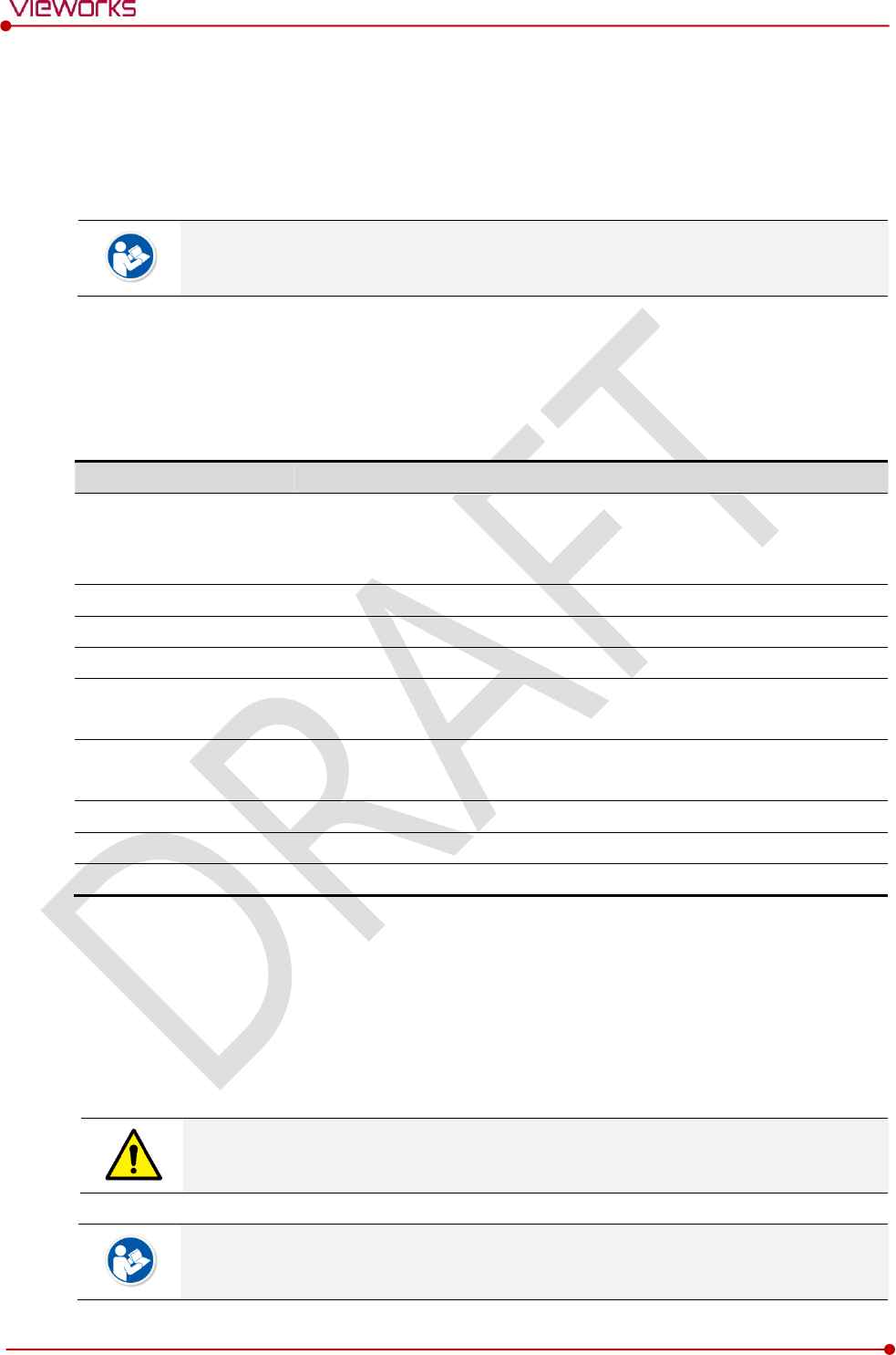
Summary list of the Detector AP LED
Information
Detector AP LED
Detector AP OFF (Communication status: Good)
Wireelss communication: 3rd level or higher
Wired communication: 1000Mbps
ON
Detector AP OFF (Communication status: Normal)
Wireelss communication: Under 2nd level
Wired communication: 100Mbps
ON
Detector AP ON
ON
Switching the status of detector AP
Blink
The wireless setting is being synchronized
Blink
Power OFF
OFF
If the LED blinks abnormally, refer to <8 Troubleshooting> to check if communication or
system error is occurred.
Rev.1.0
Page 73 of 151 VW40-153-006
VIVIX-S 1717N User Manual
4.3 Software Installation
This section gives information about how to install the software on the workstation (PC) and how to
configure the environment for software operation and communication.
Check suitability of acquiring, processing and adjusting of images by referring to the
recommended workstation specifications before the software installation.
4.3.1 Software Classification
Vieworks provides clients who purchase our detector system with software as below. You can choose and
use one of our softwares below.
Software
Description
VXvue
A program for acquiring and adjusting images developed by Vieworks.
Used for VIVIX-S detectors only.
Unnecessary to develop a separate viewer program.
VIVIX Setup
A program for setting and managing the detector and SCU.
VXvue (Viewer)
Software for acquiring, adjusting and managing the image.
XIPL
Image processing program
Document
VXvue Operation Manual
XIPL User Manual
VIVIX SDK
Software development kit for VIVIX-S detector only, provided by Vieworks.
You can develop your own software dedicated to VIVIX-S by using this kit.
SDK Package
Development package
VIVIX Setup
A program for acquiring, adjusting and managing the image.
Document
VIVIX SDK Developer Manual
4.3.2 Software Installation
For a client who uses VXvue, install the VXvue program after reading VXvue Operation Manual
carefully.
For a client who uses VIVIX SDK, install the VIVIX Setup program after reading VIVIX SDK Developer
Manual.
Be sure to install the software first with reading this manual before configuring Windows
environment.
Apart from the detector and SCU, the software can be installed separately.
Rev.1.0
Page 74 of 151 VW40-153-006
VIVIX-S 1717N User Manual
4.4 Windows Environment Setting
This section gives information about configuring Windows to communicate with the detector and SCU after
installing the VIVIX Setup program or Viewer.
The contents in this chapter are made on the basis of Windows 7.
Configuration environment can be different depending on network adaptor manufacturer
or models.
4.4.1 Network Configuration
Communication disruption between the detector (or SCU) and workstation occurs unless
the network adaptor is proper is set properly, it may cause serious repercussion to the
product and image quality.
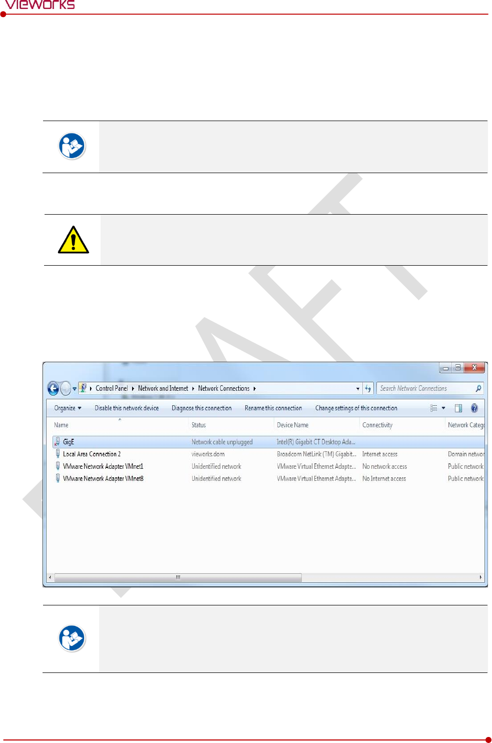
Selecting Network Adaptor
1 Click Start Control Panel Network and Internet Network and Sharing Center Change
Adapter Setting.
2 Choose the networks adaptor for communicating with the detector and SCU, and then rename it.
It is recommended to change the name of network adaptor to distinguish it from other
connection names.
Even though the name is changed, it will not affect to the operation and communication
performance of the equipment.
3 Click the chosen network adaptor with the right mouse button and click Properties to display the
Properties window.
Rev.1.0
Page 75 of 151 VW40-153-006
VIVIX-S 1717N User Manual
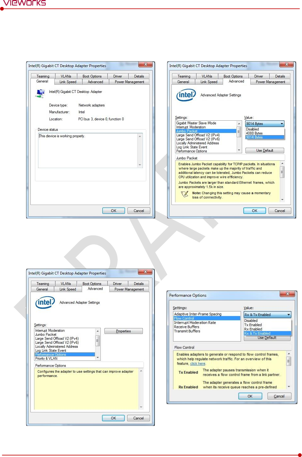
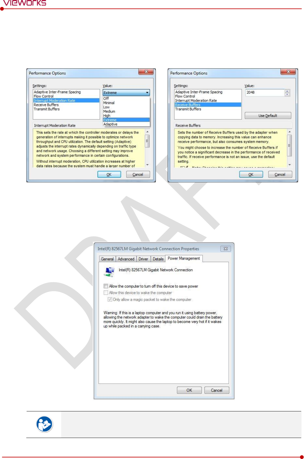
Setting Network Adaptor
1 Click Configure button to open the following dialog box, and then go to the Advanced tab.
2 Set Jumbo Packet to the maximum value. (Recommended value: 9014 Bytes)
3 Choose Performance Options in the list of Settings and click Properties button on the right.
4 Choose Flow Control in the list of Settings and select Rx & Tx Enabled on the Value list as shown
below.
Rev.1.0
Page 76 of 151 VW40-153-006
VIVIX-S 1717N User Manual
5 Choose Interrupt Moderation Rate in the list of Settings and select Extreme on the Value list as
shown below.
6 Choose Receive Buffers and set it to the maximum value.
7 Click OK button.
Deactivate Power-Saving Mode on Network Adaptor
1 Click the Power Management tab and uncheck Allow the computer to turn off this device to save
power.
2 Click OK button.
Viewer may not work normally if the power save mode is activated.
Deactivate the power save mode of all the installed network adaptors.
Rev.1.0
Page 77 of 151 VW40-153-006
VIVIX-S 1717N User Manual
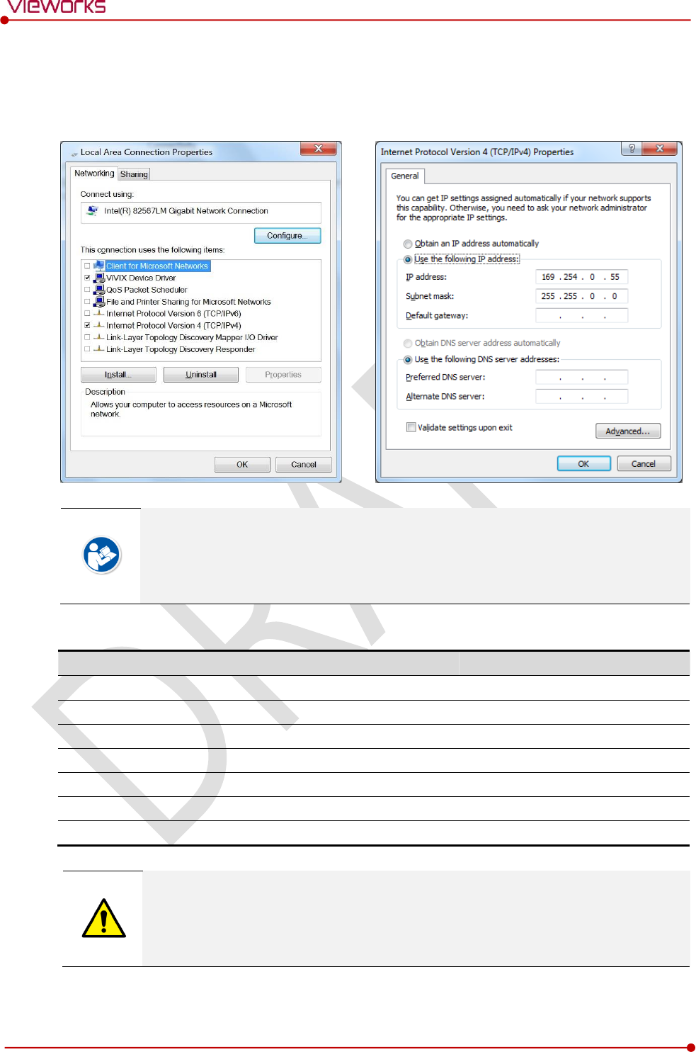
Protocol Selection and IP Address Setting
1 Choose Internet Protocol Version 4 (TCP/IPv4).and click Properties button.
2 Input the IP address and subnet mask as shown below, and then click OK button.
ViVIX Device Driver is the image filter driver for acquiring images from a detector.
It is recommended to uncheck the other items on the list except for ViVIX Device Driver
and Internet Protocol Version 4(TCP/IPv4), since they are not related with the detector
communication.
Summary of Network Configuration
Item
Value
Jumbo Packet
Maximum or 9014 Bytes
Flow Control
Rx & Tx Enabled
Interrupt Moderation Rate
Extreme
Receive Buffers
Maximum
Allow the computer to turn off this device to save power
Unchecked
IP Address
169.254.0.(50 ~ 254)
Subnet Mask
255.255.0.0
It is recommended to set the IP address and subnet mask within the range presented in
this document.
If you use IP address and subnet mask out of the suggested range, it could be difficult to
identify and resolve the cause of communication disorder.
Rev.1.0
Page 78 of 151 VW40-153-006
VIVIX-S 1717N User Manual
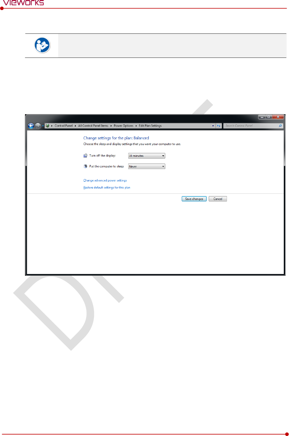
4.4.2 Disabling Sleep Mode of Monitor
If you use the sleep mode, viewer may not work normally.
1 Click Start Control Panel Power Options and then move to the Choose when to turn off the
display tab.
2 Set Put the computer to sleep to Never to disable the sleep mode.
3 Click Save changes button.

Rev.1.0
Page 79 of 151 VW40-153-006
VIVIX-S 1717N User Manual
5. Setting
This section gives information about the product setting with using the Setup program.
Start Setting
SCU Setting
Detector Setting
Changing the Wireless Setting
Rev.1.0
Page 80 of 151 VW40-153-006
VIVIX-S 1717N User Manual
5.1 Start Setting
5.1.1 Setup Program
The VIVIX Setup program provides functions for setting and managing the internal data to make VIVIX-S
1717N wireless detector and SCU work normally. In addition, The VIVIX Setup program has diagnostic
function for checking performance and abnormality of the devices as well as the image calibration function
for improving the image quality.
5.1.2 Checking Devices
Check information of the detector and SCU displayed on the Discovery list.
[TBD] – Screen Shot
Click Refresh Device List button to make the VIVIX Setup program search all detectors
and SCU connected with the same network again. If devices are not displayed, check the
power connection of the detector and click Refresh Device List button again.
List Information
List
Description
SCU
Displays discovered list of SCU devices.
Use
Double-click the option to decide wether to use SCU or not.
‘V’ is displayed when it is able to be used.
Discovery
Displays whether SCU is found out or not.
Detectors
Displays discovered list of detectors. (Max. 4)
ID
ID of detector(sequence to distinguish registered detector)
Line Trigger
Selects a pin group when using Line Trigger.
Discovery
Displays whether the detector is discovered or not.
Common
Model No.
Model name of SCU or detector
Serial No.
Serial number of SCU or detector
IP Address
IP Address of SCU or detector
MAC Address
MAC Address of SCU or detector
Rev.1.0
Page 81 of 151 VW40-153-006
VIVIX-S 1717N User Manual
The default IP address of SCU is 169.254.2.100.
The default IP address of detector is 169.254.1.10.
You can change the IP Address of detector or SCU. Refer to Change Configuration on
the next page.
MAC address is a unique indentifier of the network device. Do not change it randomly.
To change order of registered detectors’ ID, select an item and click ↑/↓buttons.
If detectors which have same IP address are connected at the same time, the address is
changed automatically to prevent address collision.
Color and Font
Information
Description
Green background
Registered status. Available to get into the device.
White background
Non-registred status. Unavailable to get into the device.
Bold font
Connected status. The device is connected.
Gray background / font
Disconnected status. The device has been connected, but is disconnected now.
The device is changed to the registered or non-registered status by double-clicking the
device name or clicking Select or Release button.
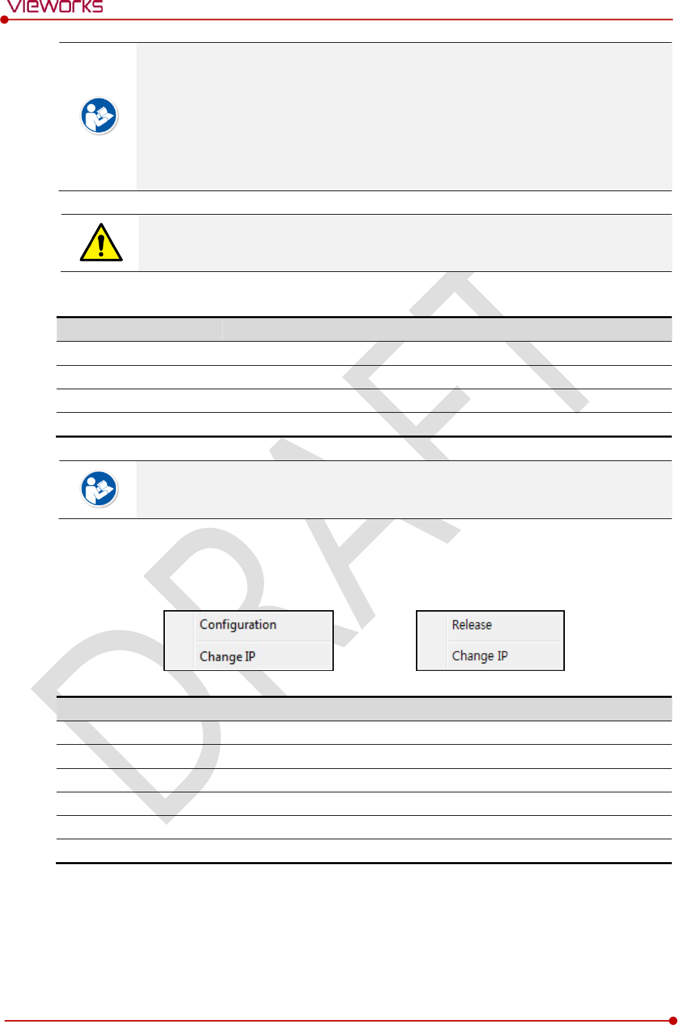
Change Configuration
Select the SCU or detector name and click the right mouse button to change its setting.
Menu
Description
SCU
-
Configuration
Changes the setting information of SCU.
Change IP
Changes IP address of SCU.
Detector
-
Release
Releases the detector to non-registered status.
Change IP
Changes IP address of the detector.
Rev.1.0
Page 82 of 151 VW40-153-006
VIVIX-S 1717N User Manual
5.1.3 Getting into the Devices
Click Next button to enter the registered SCU and detector. You can use SCU and the detector normally
when the status of SCU is Connected and the Status of detector is Initialization OK.
[TBD] – Screen Shot
Button
Button
Description
SCU
Configuration
Checks and sets information of SCU setting.
Diagnosis
Checks information of wireless AP on SCU and performs the self-diagnosis.
Detector
Configuration
Checks and changes the information of detector settings.
Calibration
Checks and calibrates the detector calibration data.
Image
Checks and diagnoses the detector and acquired image.
Diagnosis
Checks the information of detector and tests the wireless transmission
function as well as performs the self-diagnosis.
Rev.1.0
Page 83 of 151 VW40-153-006
VIVIX-S 1717N User Manual
5.2 SCU Setting
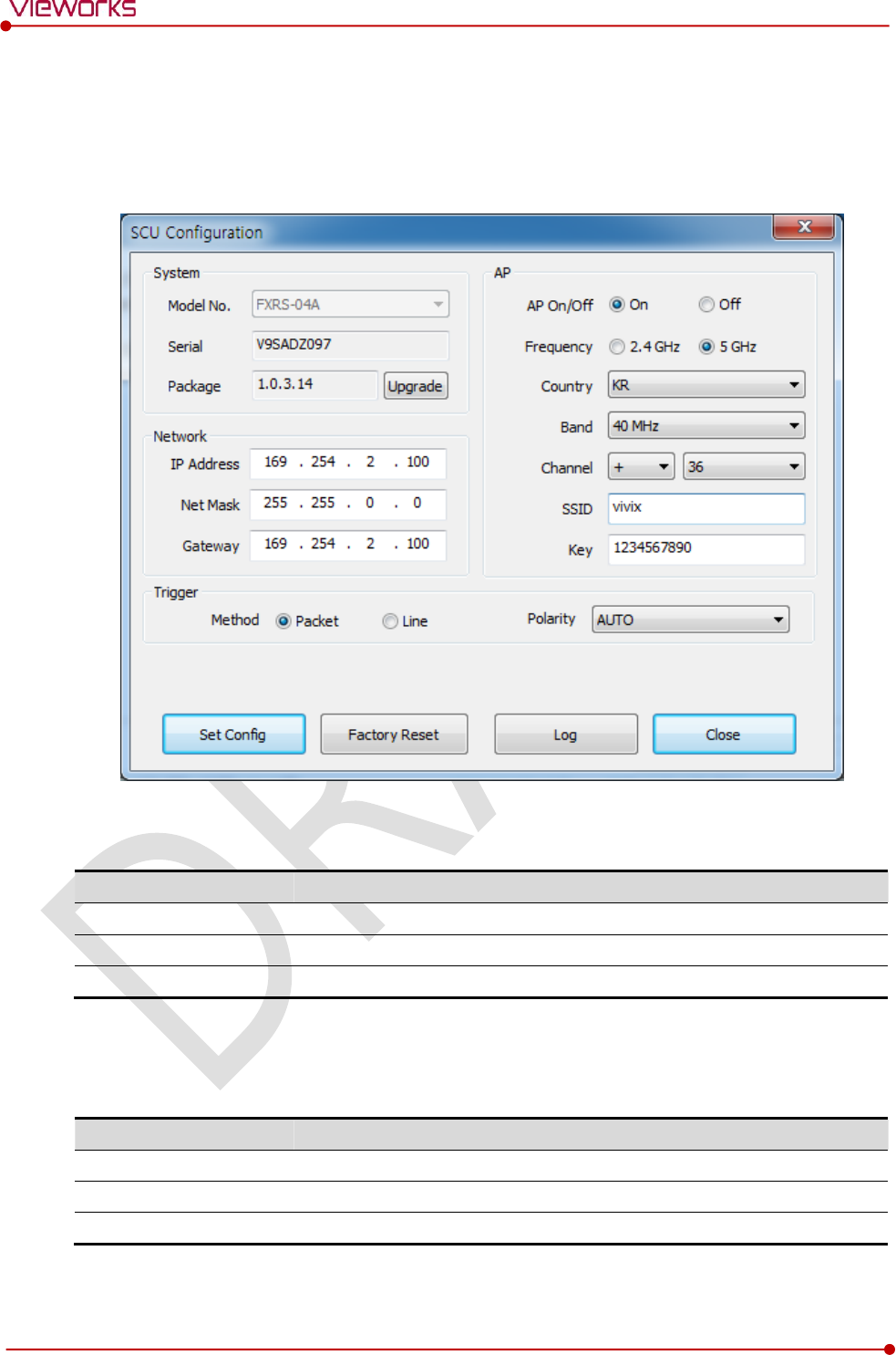
5.2.1 SCU Configuration
System
Checks and sets system information of SCU.
Item
Description
Model No
SCU model name
Serial No
SCU serial numbers
Package
Version information of SCU firmware package
Network
Checks and sets network information of SCU.
Item
Description
IP Address
IP address of SCU.
Net Mask
Subnet Mask of SCU.
Gateway
Gateway of SCU.
Rev.1.0
Page 84 of 151 VW40-153-006
VIVIX-S 1717N User Manual
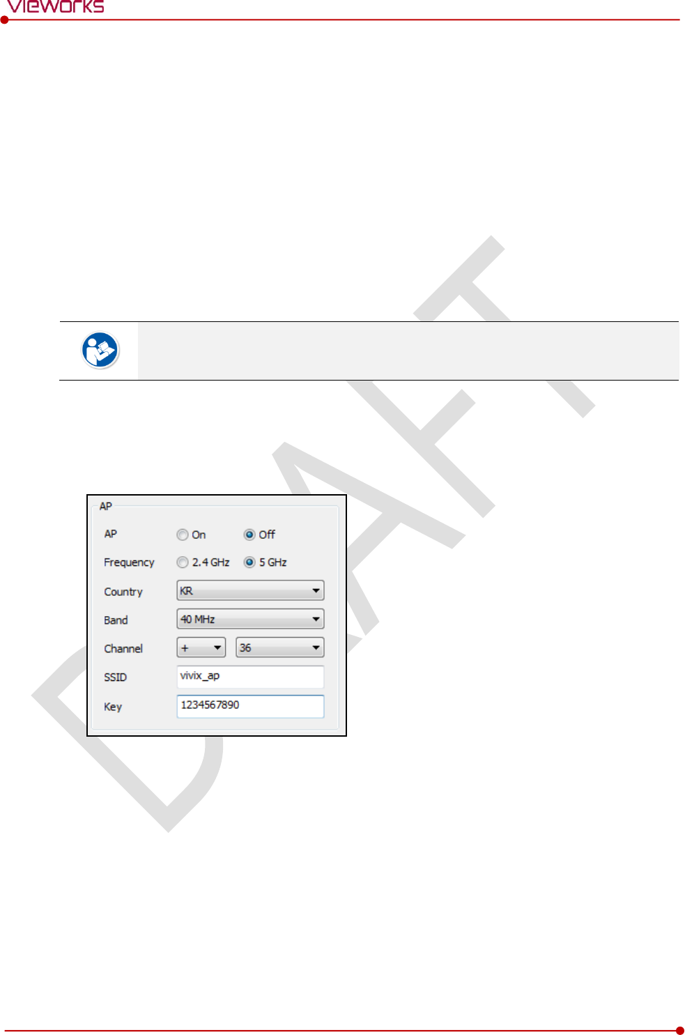
AP
Checks and sets AP (Access Point) information of SCU.
Item
Description
AP On / Off
Selects whether to use SCU AP (Access Point) mode or not.
On
Turns on SCU AP
Off
Turns off SCU AP
Frequency
Frequency channel of wireless network.
2.4 ㎓
Uses 2.4 ㎓ Frequency. (Max. 13 channels)
5 ㎓
Uses 5 ㎓ Frequency. (Max. 8 channels)
Country
Country code of using wireless network. (KR, US, EU, JP, CN)
Band
Wireless network bandwidth.
20 ㎒
Default frequency band.
40 ㎒
Expands bandwidth through channel bonding.
Channel
Wireless communication channel
SSID
Unique ID for wireless communication
Key
Unique key for wireless communication (Applied to the password only.)
13 channels can be used in 2.4 ㎓ Frequency.
8 channels can be used in 5 ㎓ Frequency
The number of serviceable channels is different according to the configured country.
Channel bonding is used for enhancing transmission speed. However, the speed may be
slowed down due to the interference of surrounding channels, even if the channels have
been bonded.
Channel items (+/-) will be activated in case of using 40㎒ frequency bandwidth. You can
set whether to bond channels with the above or below one.
SSID and Key values of the detector communicated with SCU should be set as the same.
Set SSID and Key values not to be duplicated with those of the peripheral system.
The maximum value of SSID is 20 letters and the Key is 63 letters. (Minimum Key value:
8 letters). The input letters are limited to capital / small alphabets, “-“, “_” among special
letters and numeric characters.
Wireless network setting should be done by an engineer who understands the wireless
communication and its related technique. Unless the network is set properly, a
communication error would occur or the image quality would be affected.
Rev.1.0
Page 85 of 151 VW40-153-006
VIVIX-S 1717N User Manual
Trigger
Configures trigger information for integration between SCU and X-ray generator.
Item
Description
Method
Trigger mode
Packet
Software Trigger mode
Line
Hardware Trigger mode
Polarity
Polarity of trigger signal
AUTO (Default)
Recognizes polarity automatically and handles it. (Default value)
HIGH
Handles polarity of Active High
LOW
Handles polarity of Active Low
Configuration value of trigger is applied only when Exposure mode is set DR Trigger.
Configuration value of trigger is not applied when using AED mode.
The setting of Trigger should be done by an engineer who understands about the x-ray
generator device well. Unless the device and detector are set correctly, an integration
error of x-ray generator would occur or the system operation would be affected.
Command Buttons
Item
Description
Set Config
Updates by transmitting current setting values to SCU.
Factory Reset
Resets SCU to factory default settings.
Log
Checks the logs of SCU.
Close
Closes the window of SCU Configuration. If Set Config is not performed, the
changed setting value is not transmitted to SCU.
Rev.1.0
Page 86 of 151 VW40-153-006
VIVIX-S 1717N User Manual
5.2.2 SCU Diagnosis
Self Diagnosis
You can perform self-diagnosis to check operational status of the parts in SCU.
Refer to <7.2 Product Inspection> for the detailed information on how to perform the
self-diagnosis and about the follow-up measures.
Rev.1.0
Page 87 of 151 VW40-153-006
VIVIX-S 1717N User Manual
5.3 Detector Setting
5.3.1 Detector Configuration
[TBD] – Screen Shot
System
Checks and sets system information of the detector.
Item
Description
Model No
Detector model name
Serial No
Detector serial numbers
Package
Version information of the detector firmware package
Network
Checks and sets network information of the detector.
Item
Description
IP Address
IP address of the detector
Net Mask
Subnet Mask of the detector
Gateway
Gateway of the detector
WNetwork
Sets AP (Access Point) information of wireless communication from the detector.
Item
Description
SSID
Configures wireless network ID AP from the detector.
Key
Configures wireless network key value of AP from the detector.
Wireless Only
Configures the wireless communication method of the detector.
On
The detector is operated in a wired way when a tether interface cable is
connected.
Off
The detector is operated in a wireless way when a tether interface cable is not
connected.
Rev.1.0
Page 88 of 151 VW40-153-006
VIVIX-S 1717N User Manual
AP
Checks and sets AP (Access Point) of detector information.
Item
Description
AP On / Off
Executes or disables the detector AP (Access Point) function.
Frequency
Frequency channel of wireless network
2.4 ㎓
Uses 2.4 ㎓ Frequency. (Up to 13 channels)
5 ㎓
Uses 5 ㎓ Frequency. (Up to 8 channels)
Country
Country code of wireless network (KR, US, EU, JP, CN)
Band
Wireless network bandwidth
20 ㎒
Basic Frequency Band
40 ㎒
Expands bandwidth through channel bonding.
Channel
Wireless network channel
SSID
Wireless network ID
Key
Wireless network key value (Applied to the password only.)
13 channels can be used in 2.4 ㎓ Frequency.
8 channels can be used in 5 ㎓ Frequency
The number of serviceable channels is different according to the configured country.
Channel bonding is used for enhancing transmission speed. However, the speed may be
slowed down due to the interference of surrounding channels, even if the channels have
been bonded.
Channel items (+/-) will be activated in case of using 40㎒ frequency bandwidth. You can
set whether to bond channels with the above or below one.
SSID and Key values of the detector for communicating with SCU wirelessly (WNetwork)
should be set as the same.
Set SSID and Key values not to be duplicated with those of the peripheral system.
The maximum value of SSID is 20 letters and the Key is 63 letters. (Minimum Key value:
8 letters). The input letters are limited to capital / small alphabets, “-“, “_” among special
letters and numeric characters.
Wireless network setting should be done by an engineer who understands the wireless
communication and its related technique. Unless the network is set properly, a
communication error would occur or the image quality would be affected.
Rev.1.0
Page 89 of 151 VW40-153-006
VIVIX-S 1717N User Manual
Image
Checks and sets the time limit of image transmission as well as decides whether to use the Preview item.
Item
Description
Time (sec.)
The limited time of completing image transmission.
Preview (Enable / Disable)
Sets whether to use the wireless communication way for sending preview
images.
After starting image transmission, the detector ignores the information of image re-
transmission request if the following conditions are fulfilled.
If the time limit of image transmission does not exceed.
If the image is not transmitted completely.
Power Mode
Checks and sets the management information about the power of detector.
Item
Description
Sleep
Decides whether to use the sleep mode function of the detector. (On / Off)
Sleep after (min.)
If the detector is not used for the specific setting time, it is turned to the sleep
mode. This mode activates only when the sleep mode is set. (10 / 15 / 20 / 25 /
30 min.)
Shut Down
Sets whether to use the shut down function in the detector. (On / Off)
Shut Down after (min.)
The power of detector is off if it is not used within the setting time. This menu
is activated while the Shut Down function is used. (30 / 60 / 90 / 120 min.)
Power Control
Sets standards of power supply to the detector.
by Detector
The detector is operated by power from SCU and battery.
If the power from SCU and battery is blocked, the detector is turned off.
by SCU
The detector is operated by power from SCU with connecting a tether cable. If
the power from SCU is blocked, the detector is turned off.
You can prevent unnecessary battery consumption by using the Sleep function.
When SCU supplies power to the detector with connecting a tether interface cable, the
Shutdown function cannot be operated.
If Power Off is set to by Detector and the tether interface cable is disconnected, you can
keep using the detector by the power of battery. In this case, you can turn off the
detector by pressing the power button for 3 seconds.
If a tether interface cable is disconnected while Power Off is set to by SCU, the detector
is turned off since the battery cannot supply power to the detector.
Wireless network setting should be done by an engineer who understands the wireless
communication and its related technique. Unless the network is set properly, a
communication error would occur or the image quality would be affected.
Rev.1.0
Page 90 of 151 VW40-153-006
VIVIX-S 1717N User Manual
5.3.2 Detector Power Save Function
The consumption of a battery pack can be reduced by using the power save function.
The power save function is operated only when the battery supplies power to the
detector. In other words, the power save function cannot be operated if a tether interface
cable supplies power to the detector.
Mode
Mode
Meaning
Normal
The detector can be operated and take an image at any time.
Sleep
The detector cannot be operated. User can take an image by disabling the Sleep mode.
Shut Down
The detector has been turned off. User can take an image after the detector is rebooted.
Setting Items of Power Save Function
Mode
Meaning
Normal
-
Sleep
Selects the function On (use) or Off (not use).
Sleep after (min.)
Sleep mode is activated if the detector is used during the setting time. (10 / 15 /
20 / 25 / 30 min.)
Shut Down
Selects the function On (use) or Off (not use).
Shutdown after (min.)
The detector is turned off if it is not used during the setting time. This menu is
activated while the Shut Down function is used. (30 / 60 / 90 / 120 min.)
Entry Condition of Power Save Mode
Mode
Meaning
Normal
-
Sleep
The detector turns to sleep mode if not used for the setting time (Sleep after).
Shut Down
The detector is turned off if not used for the setting time (Shutdown after) under the
sleep mode. However, if the detector is not used for the setting time (Shutdown after)
under the sleep off state, the detector is turned off.
Checks Power Save Mode
Mode
Meaning
Normal
All LED lamps are turned on.
Sleep
Power LED (Green) is blinking.
VXvue (Vieworks Viewer) indicates the state of sleep mode.
VIVIX SDK indicates the state of sleep mode.
Shut Down
All LED lamps are turned off.

Rev.1.0
Page 91 of 151 VW40-153-006
VIVIX-S 1717N User Manual
Disabling Power Save Function
Mode
Meaning
Normal
-
Sleep
1 Turns off sleep mode from VXvue (Vieworks Viewer).
2 Calls the function from VIVIX SDK to turn off sleep mode.
Shut Down
Reboots the detector by pressing a power button on the detector.
Other Information
Mode
Default value
Turnaround time
Power consumption
Normal
-
-
24V, 300mA (Standby)
24 V, 600mA (While taking
images)
Sleep
OFF / 10min.
Approx. 10 sec.
24V, Max. 150mA
Shut Down
OFF / 30min.
Approx. 15 sec.
-
Rev.1.0
Page 92 of 151 VW40-153-006
VIVIX-S 1717N User Manual
5.4 Changing the Wireless Setting
5.4.1 Switching to the Detector AP Mode
You can change the detector mode as AP by the two ways as follows.
Convert to the Detector AP mode by using the Detector AP button
Press the AP button on the detector for 5 seconds to set the Detector AP mode.
The LED of detector AP blinks in a blue color while the mode is being switched, and turns on blue
after the mode is compeleted to be converted.
This method can be used only when the detector is under the wireless communication
status without connecting a tether interface cable.
Convert to the Detector AP mode from VIVIX Setup
Choose the AP option as On or Off from the Detector Configuration dialog in VIVIX Setup program.
5.4.2 Synchronizing the Wireless Setting
Synchronize the wireless setting with a tether interface cable as follows.
1 Connect the detector and SCU with a tether interface cable.
2 Press the detector AP button for 5 seconds after the detector is turned on.
3 The LED of detector AP blinks while processing synchronization.
4 The sync information is saved automatically after it is transmitted to the detector where SSID and KEY
of SCU are connected.
5 The detector is switched to the wireless communication mode.

Rev.1.0
Page 93 of 151 VW40-153-006
VIVIX-S 1717N User Manual
6. Calibration
This chapter gives information about the calibration methods after installing a detector.
Calibration Dialogue
Detector Configuration
Calibration Guide
Calibrating by Loading the Calibration Data
Direct Calibration
Rev.1.0
Page 94 of 151 VW40-153-006
VIVIX-S 1717N User Manual
6.1 Calibration Dialogue
Use the following menus to configure the system and process calibrations.
Menu
Description
System Configuration
Configures the exposure mode, exposure-related time and Gain type.
Offset Calibration
Processes Offset calibration.
Defect Calibration
Processes calibration for defect data of the detector.
Gain Calibration
Processes calibration for image sensitivity.
Detector Configuration
Configures the detector information related to calibration and image.
The menu status is displayed as Done when each calibration is finished. You cannot
operate the detector if the status is not displayed as Done.
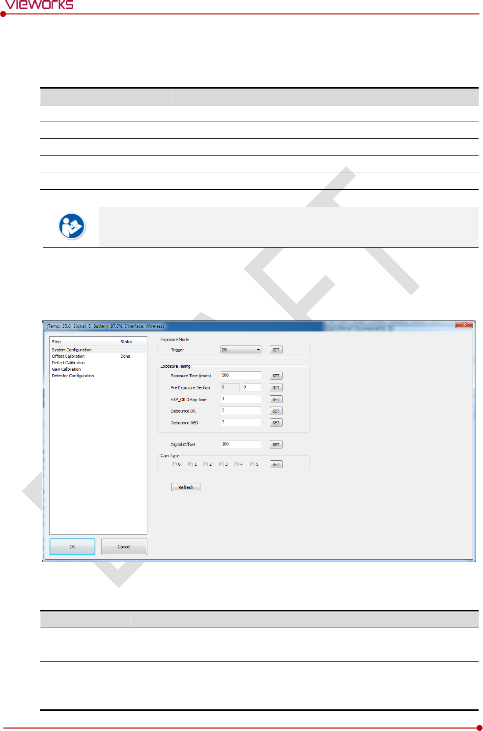
6.1.1 System Configuration Dialogue
Configure the generator interface information from System Configuration in Step.
Exposure Mode
The VIVIX-S 1717N detector provides two types of mode for taking images as follows.
Mode
Description
AED
Detects X-ray automatically without connecting the detector to X-ray generator.
The detector acquires images after the automatic detection.
DR Trigger
Detects the X-ray exposure signal of X-ray generator in advance by connecting the
detector to X-ray generator with a generator interface cable.
The detector acquires images after preparing exposure with the exposure signal.
Rev.1.0
Page 95 of 151 VW40-153-006
VIVIX-S 1717N User Manual
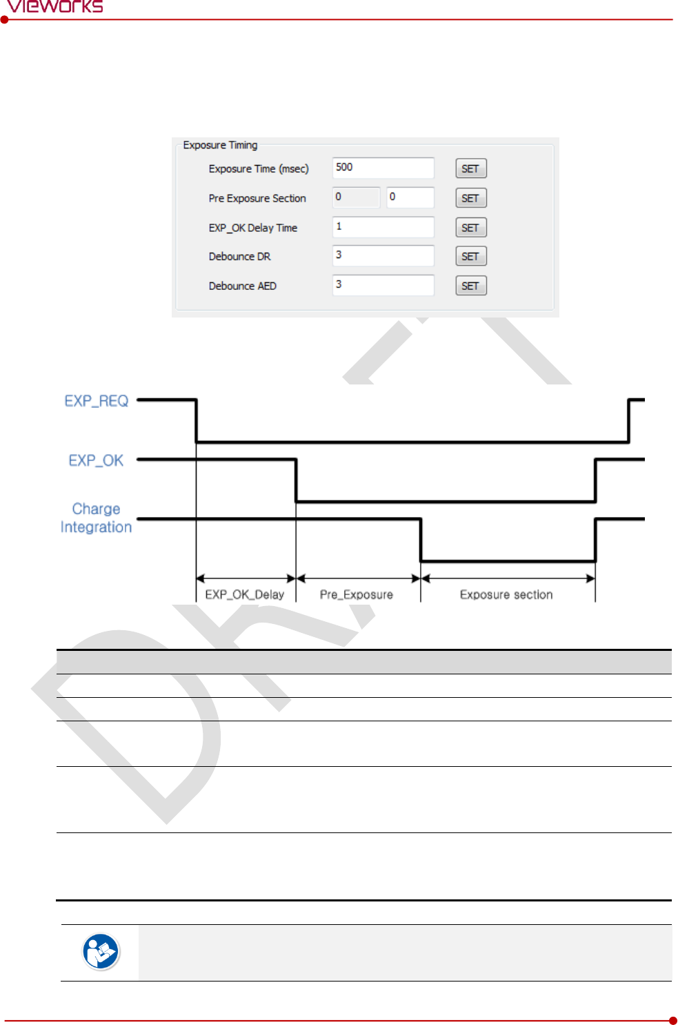
Exposure Timing
To take images exactly, set the timing information for exposure.
The information can be different depening on the characteristics of the X-ray generator.
Exposure Timing Diagram
Exposure Timing Items
Item
Default
Description
Exposure section
500㎳
Time to acquire X-ray by the detector.
Pre Exposure section
0㎳
Standby time after the detector sent EXP_OK signal to the generator.
EXP OK Delay section
1㎳
The delayed time to receive EXP_OK signal from the detector after the
generator sent EXP_REQ signal to the detector.
Debounce_DR
3㎳
The required time to check signals from the generator for preventing
image acquisition from external noise. It can be used when DR Trigger
mode is selected only.
Debounce_AED
3㎳
The required time to check sensor signal from X-ray to prevent image
acquisition from external noise. It can be used when AED mode is
selected only.
Exposure section should be set longer than the maximum exposure time to prevent X-ray
loss.
Rev.1.0
Page 96 of 151 VW40-153-006
VIVIX-S 1717N User Manual
When Exposure section is changed, make sure to create new calibration data by
processing Offset calibration and Gain calibration to get optimized images.
Pre Exposure section can be used when the time delays until the generator receives EXP-
OK signal from the detector and generates X-ray. Although Pre Exposure section is set as
0㎳ normally, it is recommended to measure and set the actual delay time of X-ray
generation to achieve the best performance of the detector. The detector sends EXP_OK
signal to the generator, then acquires X-ray after the setting time in Pre Exposure
section.
EXP OK Delay section is the delayed time between the detection time of exposure
request signal (EXP_REQ) from the X-ray generator and the time before sending exposure
respond signal (EXP_OK) to the X-ray generator. Some X-ray generators need time to
prepare detecting EXP_OK signal after sending EXP_REQ signal. This time is determined
according to the specifications of X-ray generator.
Debounce_DR is used for removing the trigger signal due to external noise when the
exposure mode is set as DR Trigger. If the value is set to less than 3㎳, the detector may
acquire undesirable images.
Debounce_AED is used for removing trigger signals due to external noise when the
exposure mode is set as AED. If the Debounce_AED value is set longer than the X-ray
exposure time, the detector cannot acquire images. If unwanted images are acquired
without X-ray exposure while the equipment is operated, set Debounce_AED with 1㎳
increments. However, we recommend you not to set the value more than 10㎳.
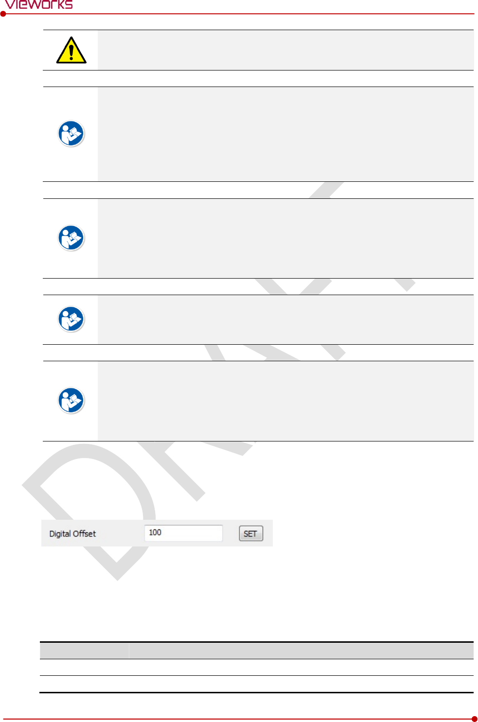
Digital Offset
After Offset Calibration, you can configure base level of pixel on Digital Offset item, in order to minimize
loss of pixel value if it is below base level point.
Gain Type
You can select the Gain Type to adjust sensitivity of the detector for acquiring X-ray images with desired
brightness according to the specifications of X-ray generator or the object type.
The following table describes the sensitivity ratio of each Gain Type of the VIVIX-S 1717N detector.
Gain Type
0
1
2
3
4
5
1717NA(W) (CsI)
0.99
1.16
1.39
1.73
2.3
3.47
1717NB(W) (Gadox)
0.87
1.0
1.18
1.44
2.17
3.25
Rev.1.0
Page 97 of 151 VW40-153-006
VIVIX-S 1717N User Manual
To acquire the optimized images, carry out the Offset calibration and Gain calibration
again after changing Gain Type.
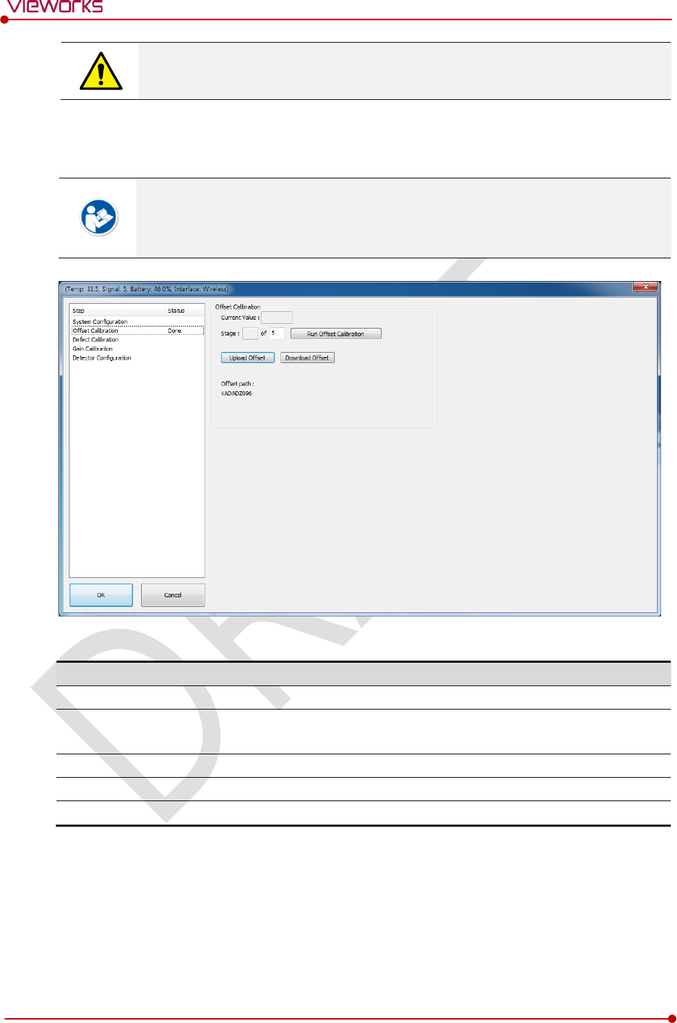
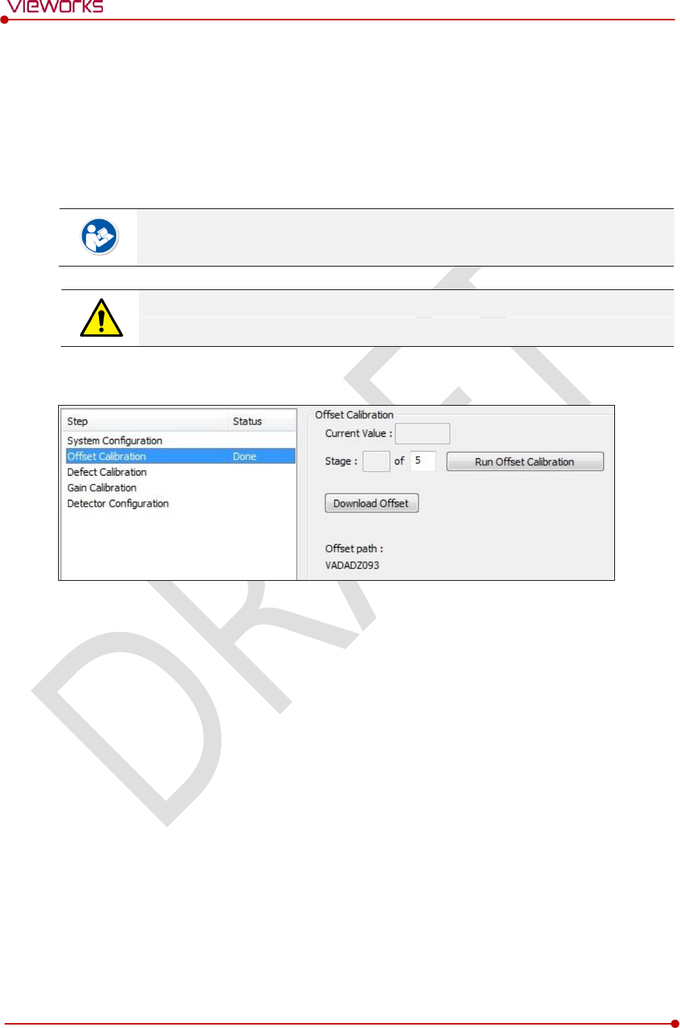
6.1.2 Offset Calibration Dialogue
Vieworks provides the Defect Map data stored in the detector. However, we recommend
you to carry out the Offset calibration and generate the Offset data by yourself as the
detector condition can be different by the operating method or use environment.
Offset Calibration
Item
Description
Current value
Shows value when performing the manual Offset calibration.
Stage
Selects the performance frequency of manual Offset calibration and
shows each calibration stage.
Run Offset Calibration
Performs the manual Offset calibration.
Download Offset
Downloads the Offset data stored in the detector.
Offset path
Shows the path of the applied Offset data.
Rev.1.0
Page 98 of 151 VW40-153-006
VIVIX-S 1717N User Manual
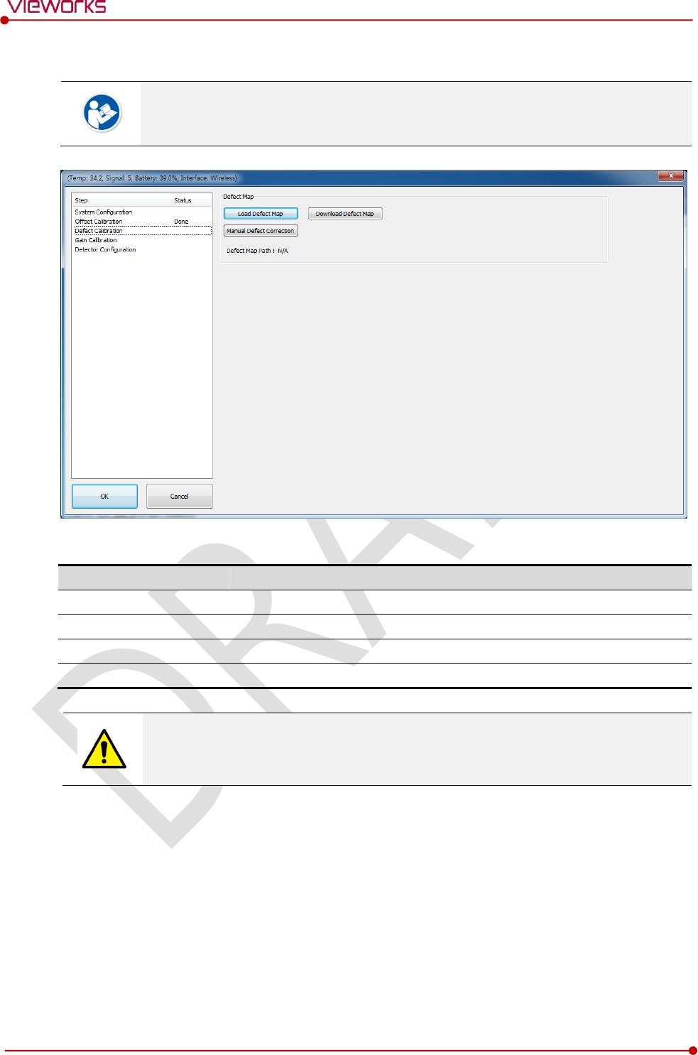
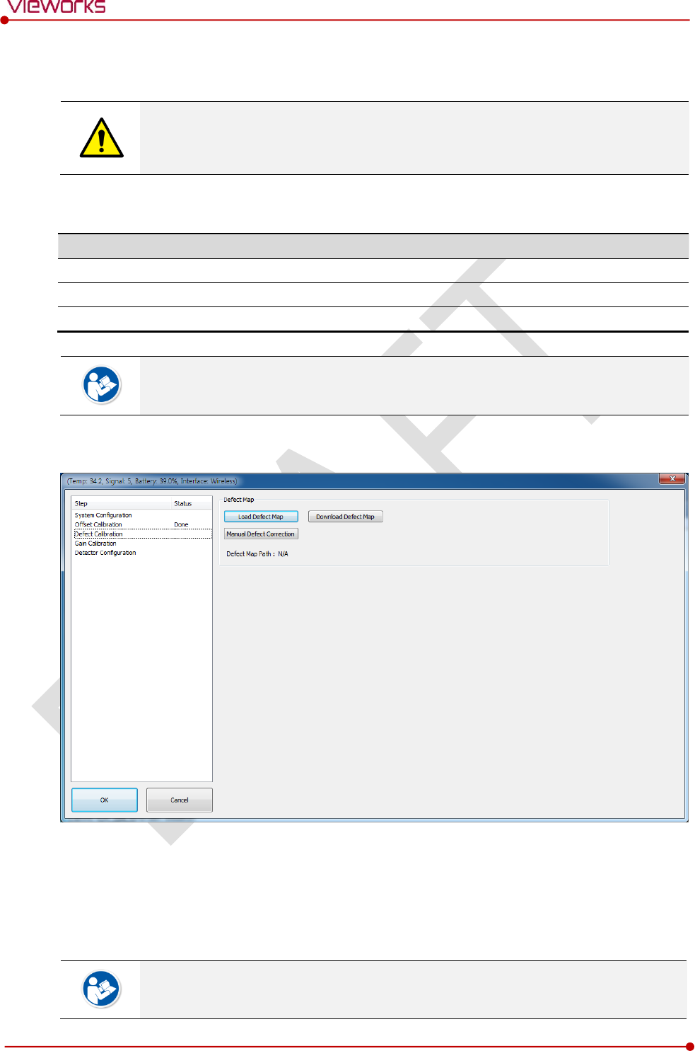
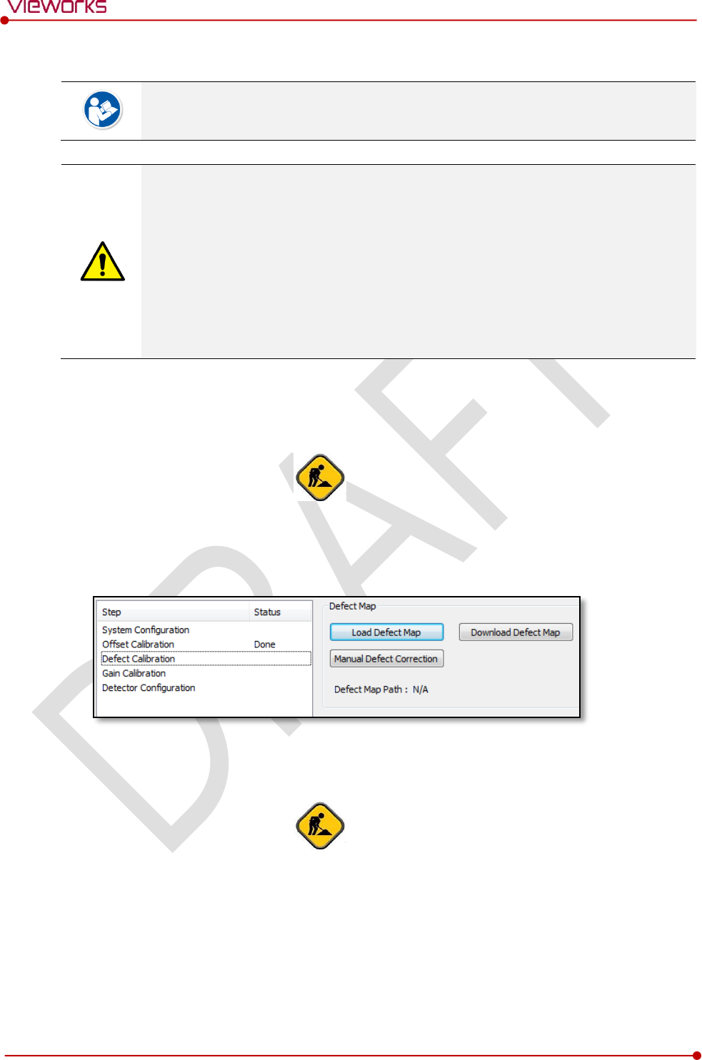
6.1.3 Defect Calibration Dialogue
Vieworks provides the Defect Map data stored in the detector. However, you should
download the data as the calibration cannot be performed in the detector automatically.
Defect Map
Item
Description
Load Defect Map
Loads the Defect Map calibration data located in the defect map path.
Download Defect Map
Downloads the Defect Map calibration data stored in the detector.
Manual Defect Correction
Calibrates the defect manually.
Defect Map Path
Shows the path of applied Defect Map data.
This Defect Map data has been generated through stringent test in the production stages
of detector. However, new defect may be newly formed while using the detector. In this
case, make sure to calibrate defects in person and generate a new defect map.
Rev.1.0
Page 99 of 151 VW40-153-006
VIVIX-S 1717N User Manual
6.1.4 Gain Calibration Dialogue
Vieworks provides the Gain data stored in the detector. However, you should download
the data as the calibration cannot be performed in the detector automatically.
[TBD] – Screen Shot
Gain Calibration
Item
Description
Target Value
Shows the target value of Gain calibration. (Recommended : 8000 or higher)
Current Value
Shows value after the exposure when processing the manual Gain calibration.
Stage
Selects the number of manual Gain calibration and shows each calibration stage.
Get
Starts the manual Gain calibration.
Cancel
Cancels the manual Gain calibration.
Load Gain
Loads the Gain calibration data located in the Gain path.
Upload Gain
Uploads the Gain calibration data to the detector for using portable mode.
Download Gain
Downloads the Gain calibration data stored in the detector.
Gain Path
Shows the path of applied Gain data.
This Gain data is provided in case the Gain calibration cannot be performed. You should
do the Gain calibration in person as the detector condition can be different by the
operating method or use environment.
Rev.1.0
Page 100 of 151 VW40-153-006
VIVIX-S 1717N User Manual
6.2 Detector Configuration
From the Detector Configuration dialog, you can configure the detector and check the images before or
after doing calibration.
[TBD] – Screen Shot
Function List
Item
Description
Detector Direction Compensation
Sets the displayed direction of image.
Effective Area
Sets effective area of an image.
Auto Offset Refresh Setting
Sets conditions of automatic Offset Refresh.
Time Interval (min.)
Checks cycle of temperature change
Temperature Interval (℃)
Difference of over-temperature.
Number of shot
Number of Offset Refresh.
Edge Masking (On / Off)
Sets outside of the effective area to specific values.
OSF
Chooses whether to use OSF or not.
Button
Item
Description
Pan
Moves an image to the desired location.
Zoom
Extends or constract an image.
W/L
Adjusts window level of an image.
Fit
Displays an image by adjusting it to the screen.
E.A.
Sets the effective area of an image with a mouse.
ROI
Sets the image area of interest.
Effective Area On / Off
Displays effective area of an image only.
You can only change the displayed direction of an image from Detector Direction
Compensation. The direction of an original image cannot be changed.
Effective Area can be changed within the effective range which has been configured at
the time of the first shipment of detector.
Once Use offset refresh is used, the offset refresh is processed automatically as follows.
Checks temperature difference of the detector between current temperature and the
previous one at the time of offset refresh in every setting time from Time Interval.
If the temperature difference is more than the one set in Temperature Interval, the
offset refresh is carried out a number of times set in Number of shot.

Rev.1.0
Page 101 of 151 VW40-153-006
VIVIX-S 1717N User Manual
If you use VXvue, a pop-up message will be displayed before the offset refresh.
Auto offset refresh will be performed by clicking OK button.
OSF is the auxillary function for stabilizing pixel value of an image to the default value
rapidly.
The pixel value can be displayed equally by using OSF under the environment where the
pixel value of X-ray image is required to display.
Whether to use OSF or not does not affect the X-ray image quality.

Rev.1.0
Page 102 of 151 VW40-153-006
VIVIX-S 1717N User Manual
6.3 Calibration Guide
The different installation environment of each detector and unique features of the X-ray generator device
can affect the acquired images. Therefore, the certified engineer from Vieworks should do the detector
calibration after installing it. Otherwise, the image quality can be affected seriously.
Vieworks provides two types of calibration for performing calibration.
Performing calibration by loading the calibration data provided by Vieworks.
The service engineer proceeds calibration and generate calibration data.
We strongly recommend the service engineer to carry out the calibration in person since
the detector condition and image quality can be different by the operation method or
use environment.
Rev.1.0
Page 103 of 151 VW40-153-006
VIVIX-S 1717N User Manual
6.4 Calibrating by Loading the Calibration Data
Vieworks provides the calibration data stored in the detector. Although the Offset
calibration is performed automatically, you need to download both Defect and Gain
calibration data since their calibration cannot be performed in the detector automatically.
6.4.1 Preparing Calibration Data
File
Description
Offset
Detector Offset data
Gain
Calibration data for image sensitivity
Defect Map
Defect calibration map data
It is not necessary to download the Offset calibration data since the data is used in the
detector.
6.4.2 Loading Defect Calibration Data
1 Select Defect Calibration from the Step list.
2 Click Download Defect Map button to assign the path of local HDD, and download the Defect Map
calibration data.
3 Click Load Defect Map button to load the calibration data.
The calibration menu status is displayed as Done when the Defect calibration data is
loaded completely.
Rev.1.0
Page 104 of 151 VW40-153-006
VIVIX-S 1717N User Manual
Be sure to select the Defect Map data file provided with a detector. If the file has a wrong
serial number or you select a wrong file, an error message will be displayed.
Vieworks provides the Defect Map data stored in the detector. However, you should
download the data as the calibration cannot be performed in the detector automatically.
This Defect Map data has been generated through stringent test in the production stages
of detector. However, new defect may be newly formed while using the detector. In this
case, make sure to calibrate defects in person and generate a new defect map.
6.4.3 Loading Gain Calibration Data
[TBD] – Screen Shot
1 Select Gain Calibration from the Step list.
2 Click Download Gain button to assign the path of local HDD.
3 Download the Gain calibration data by clicking Load Gain button.
The calibration menu status is displayed as Done when the Gain calibration data is
completed to be loaded.
Be sure to select the Gain calibration data file provided with a detector. If the file has a
wrong serial number or you select a wrong file, an error message will be displayed.
Vieworks provides the Gain calibration data stored in the detector. However, you should
download the data as the calibration cannot be performed in the detector automatically.
This data is provided in case the Gain calibration cannot be performed. You should do
the Gain calibration in person as the detector condition can be different by the operating
method or use environment.
Rev.1.0
Page 105 of 151 VW40-153-006
VIVIX-S 1717N User Manual
6.5 Direct Calibration
6.5.1 Prepration
Precheck the state of X-ray generator and console.
Precheck the state of X-ray tube.
It is recommended you to check if X-ray dose value of the generator is exact by using the
device like a dose meter.
Make sure to preheat the detector for 30 minutes before starting calibration. The result of
measurement can be incorrect if the detector is not preheated sufficiently.
6.5.2 Offset Calibration
1 Set the number of Stage as 5 in the Offset Calibration area.
2 Click Run Offset Calibration button and progress the Offset calibration.
Rev.1.0
Page 106 of 151 VW40-153-006
VIVIX-S 1717N User Manual
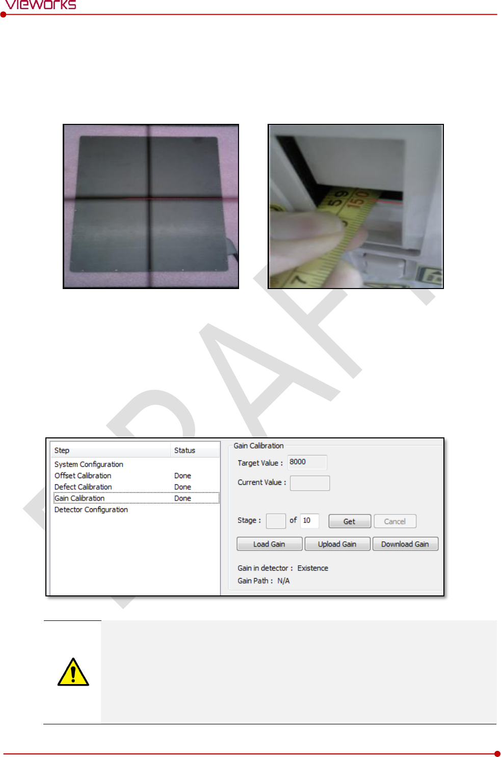
6.5.3 Gain Calibration
1 Put a collimator on center of the detector, and open the collimator completely.
2 Adjust SID as 130㎝ ~ 150㎝ to make X-ray exposure range include the detector.
3 Remove any objects or foreign materials between the tube and the detector.
4 Choose Gain Calibration -Normal.
5 Set the tube voltage of X-ray generator as 70㎸ ~ 80㎸.
6 While acquiring images, adjust the X-ray dose condition (㎃ or ㎳) until Current Value of the Gain
Calibration area is formed between 8000 and 10000.
7 Set the exposure number of Stage as 10 when the adjustment of exposure condition is completed.
8 Click Get button, and keep making an X-ray exposure at 15 sec intervals.
9 Save the Gain Calibration data as a file.
Make sure to progress Gain Calibration again if the cases below are applicable.
When the settings of Exposure Section or Gain Type is changed from the VIVIX Setup
program.
When the exposure devices like X-ray generator are repaired.
When the exposure environment is changed.
When the service engineer decides that it is need to progress Gain Calibration.
Rev.1.0
Page 107 of 151 VW40-153-006
VIVIX-S 1717N User Manual
6.5.4 Auto Defect Correction
While operating the detector, defect pixels may appear on the image. In this case, use the
defect auto correction to calibrate the defect pixels.
Be sure to check the followings before acquiring the FLAT image.
Preheat the detector for 30 minutes or more.
The recommend SID is 150 ㎝ (distance between X-ray tube and detector)
Open the collimator of X-ray tube completely.
Align the center of the detector with the center of collimator.
Keep everything away from the detector surface.
Adjust the x-ray dose to make the pixel value from 900 ~ 1100.
Check if the calibration data (Offset, Defect Map, Gain) is registered normally.
1 Make an exposure of FLAT images from the Image dialog box.
2 Click Save Image button to save images to the user-defined folder. (saved as a raw file.)
[TBD] – Screen Shot
3 Close the Image dialog box, and open the Calibration dialog box.
4 Choose Defect Calibration as follows and click Manual Defect Correction button.
5 Move to the folder where the raw file is saved and select the file.
[TBD] – Screen Shot
Rev.1.0
Page 108 of 151 VW40-153-006
VIVIX-S 1717N User Manual
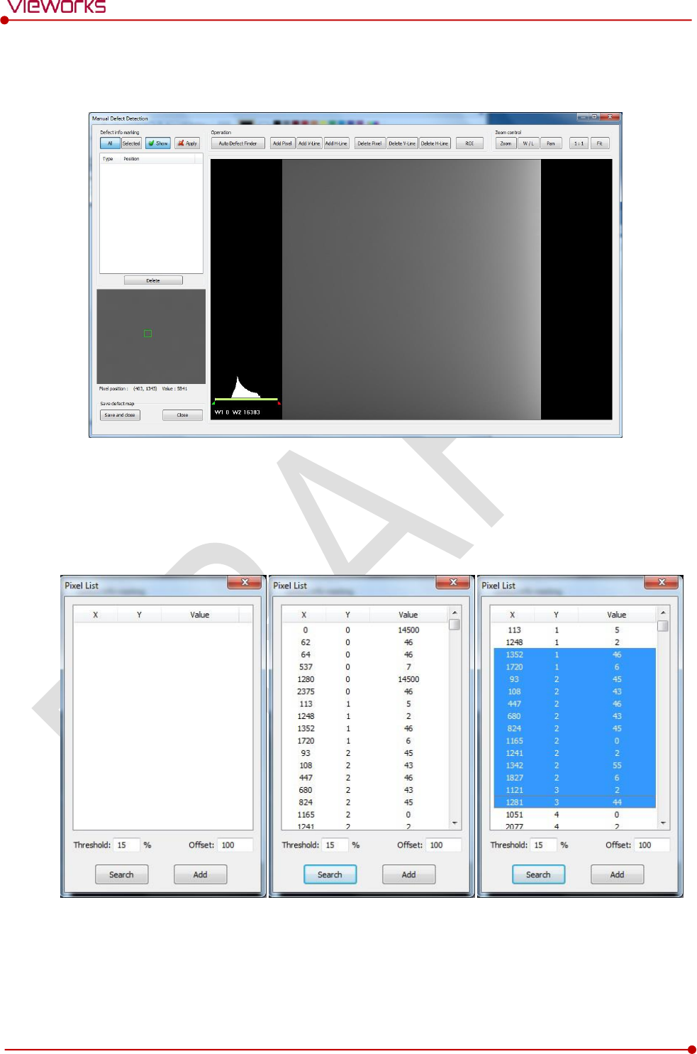
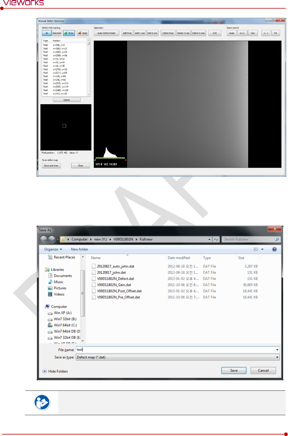
6 The Manual Defect Detection screen will be displayed.
7 Click Show and Apply buttons on the top left and then click Auto Defect Finder button.
8 Input 15% for Threshold, and 100 for Offset at the bottom of the Pixel List screen.
9 Click Search button at the bottom of the screen. The coordinates of defect pixels and Gray level values
are displayed on Pixel list.
10 While pressing the Ctrl or Shift key, select the coordinate of defect pixels to be added to Defect Map.
11 Click Add button to add the selected items to Pixel List in Manual Defecct Detection.
12 Check if the selected defect pixels are added to the pixel list on the left.
Rev.1.0
Page 109 of 151 VW40-153-006
VIVIX-S 1717N User Manual
13 Click Save and Close button at the left bottom.
14 Save the newly generated Defect Map data to the path where the Calibration data has been stored.
It is recommended to save the newly generated Defect Map data with a different name to
preserve the past Defect Map data.
Rev.1.0
Page 110 of 151 VW40-153-006
VIVIX-S 1717N User Manual
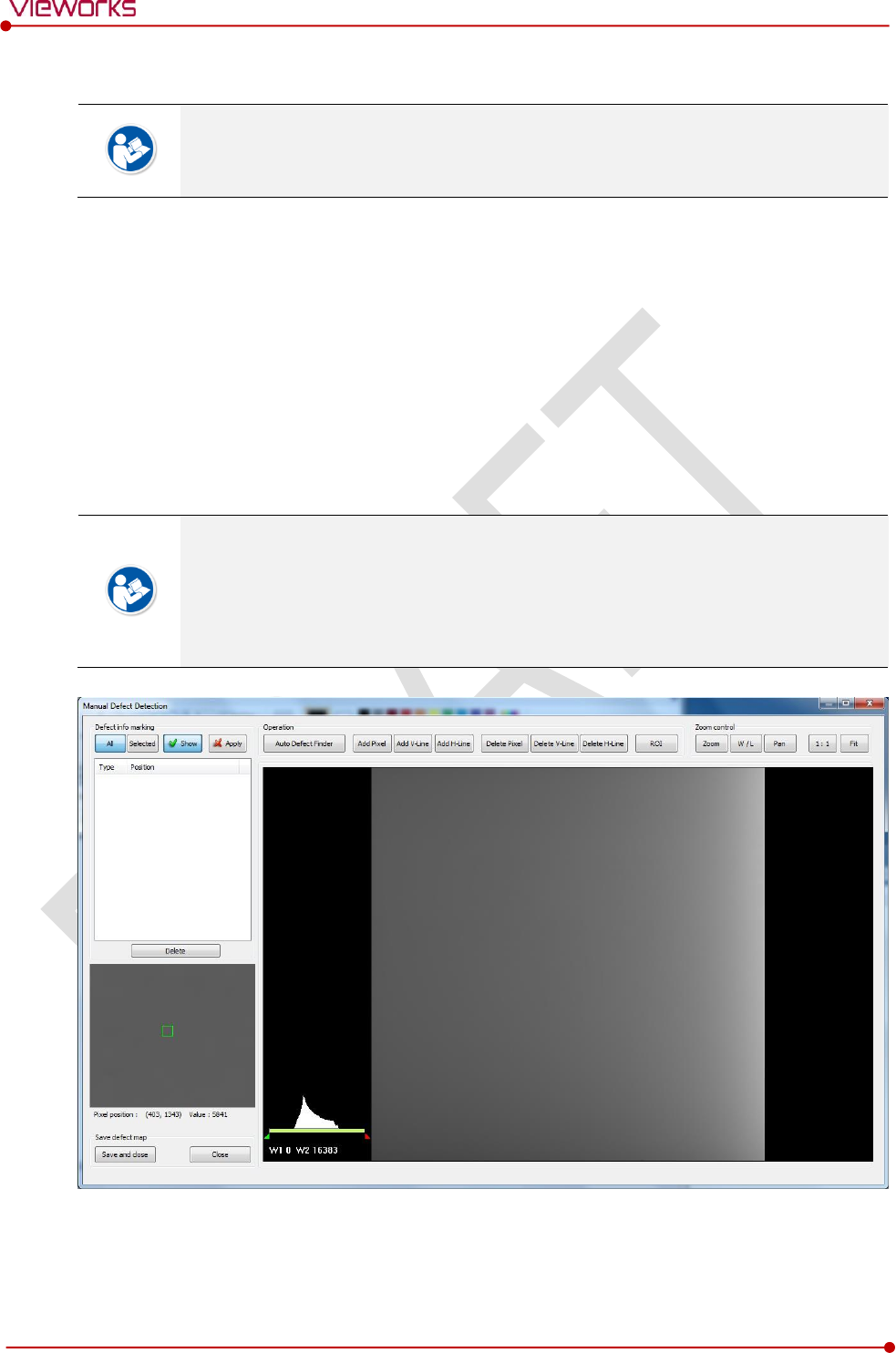
6.5.5 Manual Defect Correction
Execute Manual Defect Detection when the defect pixels are visible to the naked eye
even the automatic defect correction (step 1~14) is processed. Manual Defect Detection
is divided into the pixel type and line type.
Manual Defect Correction in Pixel Type
1 Make sure to carry out the automatic defect correction from 1 to 14 steps first.
2 Click Show and Apply buttons on the left top of Manual Defect Detection.
3 Press and hold the right mouse button and move it to left/right/top/ bottom in the FLAT image to
adjust the brightness until you can verify the image with the naked eyes.
4 Click Add Pixel Button.
5 Use the Zoom or Pan function properly to find and click the location of defect pixel. Red point will be
displayed and coordinate of the pixel will be added on the Detect Map List on the left upper.
6 Click Save and Close button to save the Defect Map data with a new name.
If a selected pixel has a difference in the brightness or gray level value (more than 15%)
compared to the adjacent pixels, the pixel may be regarded as a defect pixel.
A window located on the left top will magnify and display the pixel where the mouse
pointer is located. The coordinate and Gray level value of the pixel will be displayed
under the window.
Rev.1.0
Page 111 of 151 VW40-153-006
VIVIX-S 1717N User Manual
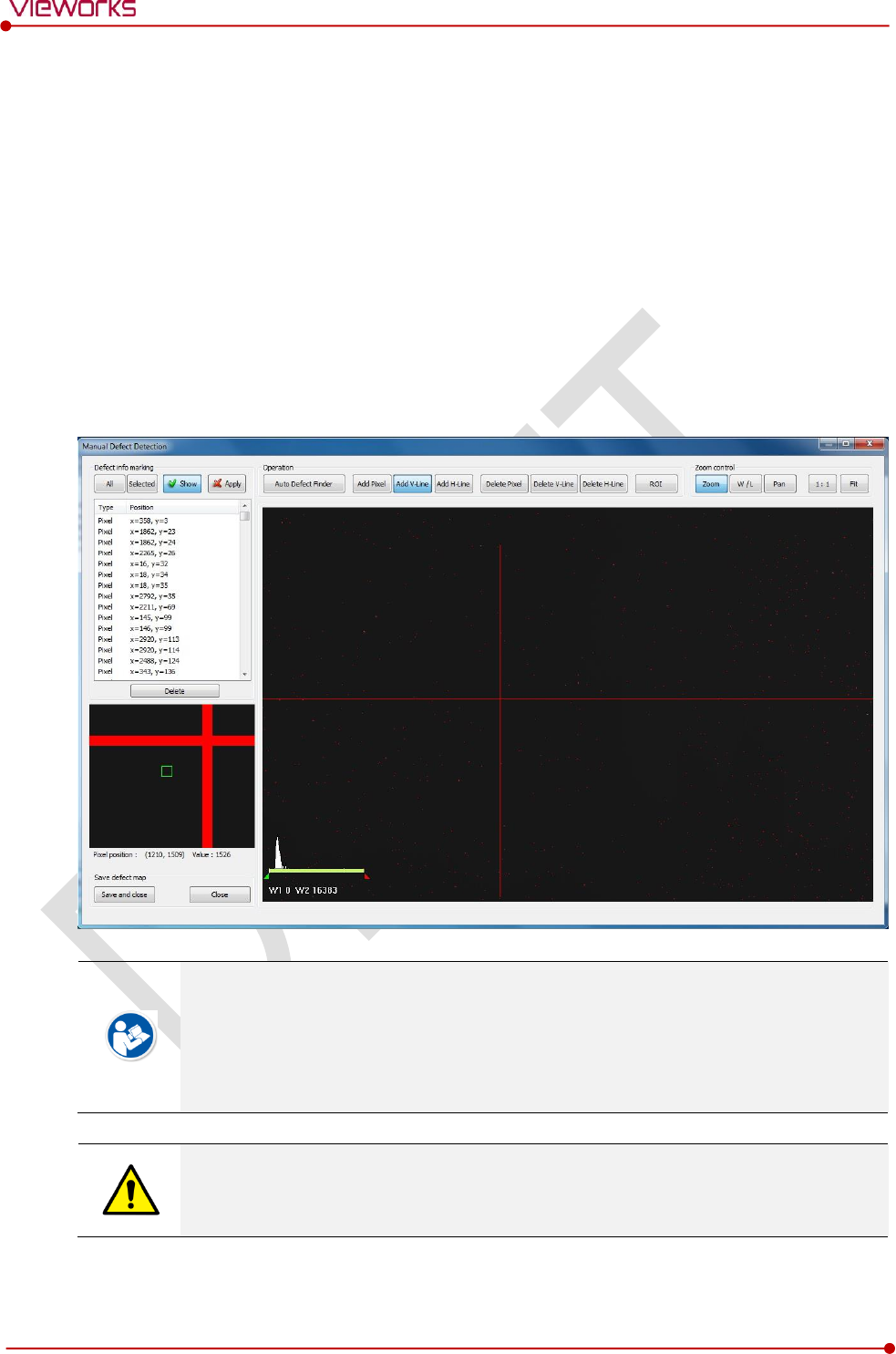
Manual Defect Correction in Line Type
1 Make sure to carry out the automatic defect correction from 1 to 12 steps first.
2 Click Show and Apply buttons on the left top of Manual Defect Detection.
3 Press and hold the right mouse button and move it to left/right/top/bottom in the FLAT image to
adjust the brightness until you can verify the image with the naked eyes.
4 Find and move to the start point of defect lines (line type) on the image.
5 Click Add V-Line or Add H-Line button.
6 Press and hold the left mouse button on the first defect pixel, move the mouse to the opposite
direction and release the mouse button on the last pixel of Line Defect pixel.
7 A red line will be displayed on the image and check if pixels on the line are added to the Defect Pixel
list.
8 Click Save and Close button to save the newly generated Defect Map data with a new name.
If a selected pixel has a difference in the brightness or gray level value (more than 15%)
compared to the adjacent pixels, the pixel may be regarded as a defect pixel.
A window located on the left top will magnify and display the pixel where the mouse
pointer is located. The coordinate and Gray level value of the pixel will be displayed
under the window.
If there are pixels existed without defect correction even though you conduct the manual
defect correction, get technical support from the person in charge of Vieworks or a
certified engineer by Vieworks.

Rev.1.0
Page 112 of 151 VW40-153-006
VIVIX-S 1717N User Manual
Functions of Manual Defect Detection
Function
Description
Show
Decides whether to indicate the selected defect on the image
Apply
Decides whether to apply Defect in the list to the calibrated image.
All
Applies to all coordinates of defects added to the list
Selected
Applies to relevant coordinates of the selected defects from the list only.
Auto Defect Finder
Performs the auto defect correction.
Delete
Deletes the selected items from the list.
Add Pixel
Adds one defect pixel to Defect Map List.
Add V-Line
Adds vertical line type of defect pixels to Defect Map List
Add H-Line
Adds horizontal line type of defect pixels to Defect Map List.
Delete Pixel
Deletes the defect pixel of a point on list of Defect Map.
Delete V-Line
Deletes the defect pixel of vertical line on list of Defect Map.
Delete H-Line
Deletes the defect pixel of horizental line on list of Defect Map.
ROI
Marks the area of interest.
Zoom
Zoom in or out the image.
W/L
Adjusts the window level of the image to change the brightness.
Pan
Moves the image to a desired location.
1:1
Displays the image as 1:1 ratio.
Fit
Displays the image as fitting it on the screen.
Save and Close
Saves the changed defect pixel information as Defect map data.
Close
Closes the window without saving the changed defect pixel information

Rev.1.0
Page 113 of 151 VW40-153-006
VIVIX-S 1717N User Manual
7. Diagnosis, Inspection and
Maintenance
This section gives information about diagnosis, inspection & maintenance of the product.
Diagnosis
Product Inspection
Cleaning and Disinfection
Product Initialization
Replacing the Fuse of SCU
Rev.1.0
Page 114 of 151 VW40-153-006
VIVIX-S 1717N User Manual
7.1 Diagnosis
7.1.1 Image Diagnosis
Check the image quality through Diagnosis tools after installing the detector or before
usage. If the problems with regard to products or image occur during diagnosis, try to do
a calibration again. If the problems are not solved, consult the sales representative in
Vieworks or a service engineer.
You can acquire and review an image from the Image window in VIVIX Setup program.
You can review images by acquiring them through real exposure or getting Dark image by clicking Get
Normal Image button.
The number of images, pixel value and ROI value will be displayed.
The effective area or whole area of an image can be checked.
It is also available to check the image by changing its direction.
Save the reviewed image as a raw one to analyze.
You can acquire an image either applying Offset / Gain data or not.
[TBD] – Screen Shot
Diagnostic Functions
Item
Description
Pan
Press and drag a mouse button to move the image to the desired position.
Zoom
Press and hold a mouse button to move the image upwards or downwards for
expanding / reducing the image.
W/L
Press and hold a mouse button to move the image to up/down/right/left for
adjusting its window level. This function can be used without clicking W/L button, but
with the right mouse button basically.
Fit
Sets the image to the center, which was moved by using Pan function.
Statistic
Clicks and drags the left mouse button to set arbitrary area. The coordinate, min/max
value, average and standard deviations are displayed on Pickup ROI at the left side
of image.
ROI
Clicks and drags the left mouse button to set window level automatically on a basis
of min/max value of the configured area.
Zoom
Expands the image
X1
2 times
X2
4 times
X4
16 times
Offset
Applicability of Offset data
Rev.1.0
Page 115 of 151 VW40-153-006
VIVIX-S 1717N User Manual
On
Acquires an image with applying Offset data.
Off
Acquires an image without applying Offset data.
Gain
Applicability of Gain data
On
Acquires an image with applying Gain data.
Off
Acquires an image without applying Gain data.
Effective Area
Applicability of Effective Area in Detector Configuration dialog.
On
Applies effective area of the detector to the image.
Off
Applies whole area of the detector to the image.
Direction
Applicability of Detector Direction Compensation in Detector Configuration dialog.
On
The image is displayed according to the configured direction.
Off
The image is displayed as a default direction. The image starting point (0,0) is located
on the left top of the image.
Get Backup Image
Imports or deletes the backed-up images.
Get Normal Image
Acquires a dark image without X-ray shooting.
Save Image
Saves the image as a raw one.
Close
Closes the Diagnosis dialog.
You can only change the displayed direction of an image in VIVIX Setup program from
Detector Direction Compensation. The direction of an original image cannot be
changed.
Rev.1.0
Page 116 of 151 VW40-153-006
VIVIX-S 1717N User Manual
7.1.2 Battery Pack Diagnosis
Install the battery pack to the detector and check the voltage and remaining amount of
the battery pack. Furthermore, always check the remaining amount of the battery pack
during use of the detector. If performance of the battery pack has some problems, consult
the sales representative in Vieworks or a relevant engineer.
The battery pack belongs to consumables which performance will be decreased as time
passed. Make sure to check the battery life during usage.
Check remaining amout of battery pack
The battety remains is noticed as a level or percentage (%).
Check the battery status from the Information tab of the Diagnosis dialogue in VIVIX Setup program.
It is also available to check the battery remains from the LED on the side of detector.
You can check the battery remains from VXvue (Vieworks Viewer) or VIVIX SDK.
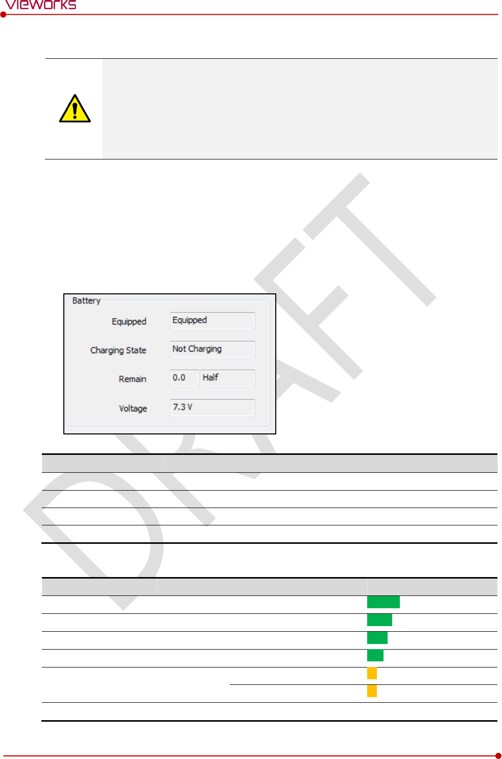
Item
Description
Equipped
The install state of a battery pack. (Equipped / Not Equipped)
Charging State
The charging state of a batter pack. (Charging / Not Charging)
Remain
Battery remains
Voltage
Battery voltage
Display of Bettery Remains
Level
Value
Battery Remains
LED Display
Full
5
81% ~ 100%
5th level
Half Quarter
4
61% ~ 80%
4thlevel
Half
3
51% ~ 60%
3rd level
Quarter
2
31% ~ 50%
2nd level
Low
1
11% ~ 30%
1st level
1% ~ 10%
Blink
Unknown
0
Off
Rev.1.0
Page 117 of 151 VW40-153-006
VIVIX-S 1717N User Manual
If the remaining of battery is under 30% or at the 1st level, the detector LED for noticing
battey remains changes from green to orange color.
The warning information related to battery remains is displayed from VXvue.
The warning information related to battery remains is noticed from VIVIX SDK.
If the remaining of battery is under 10%, the detector LED for noticing battey remains
blinks in orange color.
If the remaining of battery is under 30% or at the 1st level, the system warns low battery
and the detector will be turned off automatically if the battery is being consumed for a
specific period of time. Therefore, it is recommended to change the battery when a
warning message or indicator is displayed.
7.1.3 Wireless Communication Diagnosis
In case of using the detector with wireless communication way, make sure to check the
status of wireless communication before starting to use. If the status of wireless
communication is bad, the speed of acquiring images will be very slow or failed to acquire
images. Try to check the surrounding wireless communication status not to occur
communication interference. If wireless communication module in the detector has
problems, consult the sales representative in Vieworks or a relevant engineer.
Check the Connection Status
Check the wireless communication state from the Information tab of the Diagnosis dialogue in VIVIX
Setup program.
User can check the connection status of wired or wireless detector through VXvue or VIVIX SDK.
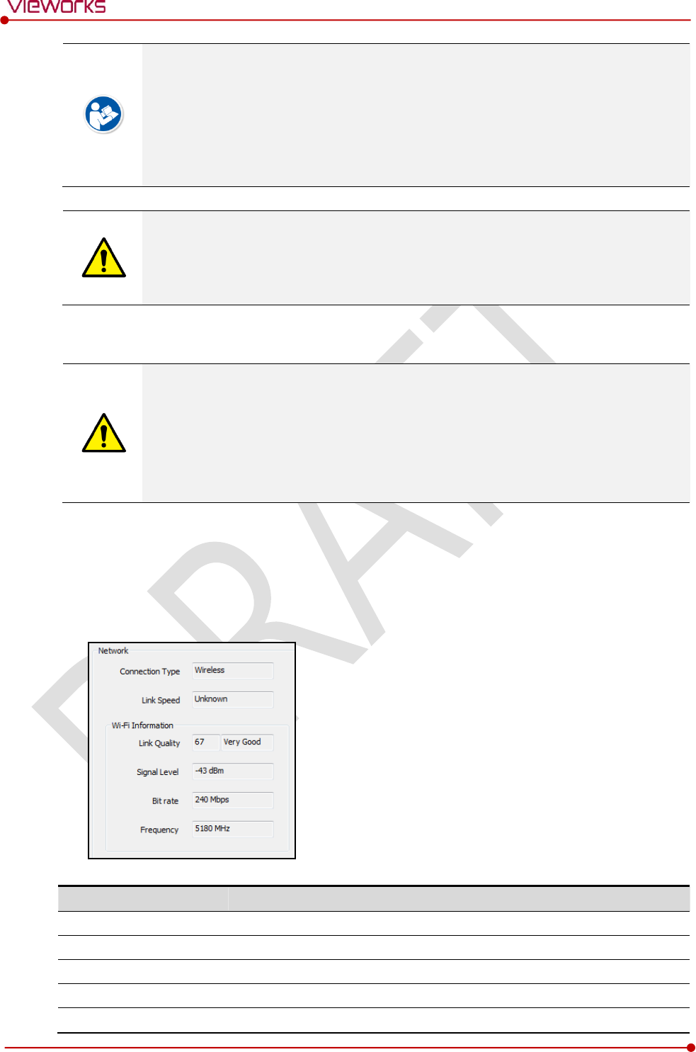
Item
Description
Connection Type
Indicates the connection mode. (Wireless / Tether)
Link Speed
Connection status in the wired mode. (1000Mbps / 100Mbps)
Link Quality
Link Quality (Status of the connection quality) value
Signal-level
Singal strength
Bit rate
Transmission / reception speed
Rev.1.0
Page 118 of 151 VW40-153-006
VIVIX-S 1717N User Manual
Frequency
Frequency of the connected AP (Access Point)
Check the Strength of Wireless Communication Signal
The signal strength of wireless communication is provided as 6 stages (0 ~ 5).
Level
Level
Link Quality
Meaning
Very Good
5
66 ~ 70
The communication is running smoothly, and it
ensures performace of the image acquisition.
Good
4
56 ~ 65
Normal
3
41 ~ 55
The communication status is normal, but it does not
ensure performace of the image acquisition.
Bad
2
31 ~ 40
The communication status can become unstable.
Very Bad
1
1 ~ 30
Impossible to communicate normally.
Unknown
0
0
The communication is disconnected.
The communication is not running smoothly when the strength of wireless communication
is under the 2nd stage. Therefore, it is required to check the surrounding wireless
communication status.
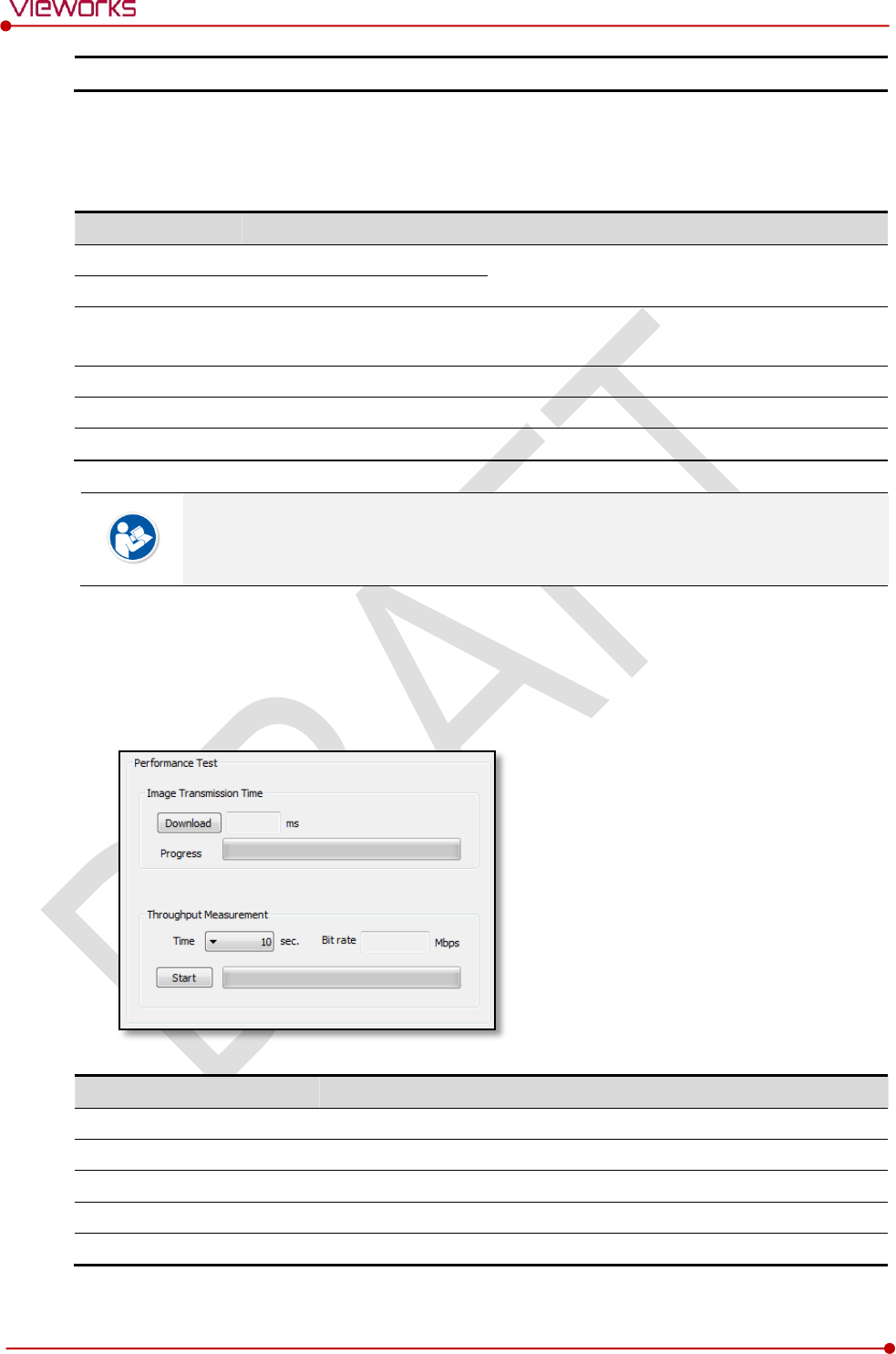
7.1.4 Communication Speed Diagnosis
The communication speed can be diagnosed from the Information tab of Diagnosis dialogue in
VIVIX Setup program.
Item
Description
Image Transmission Time
Image transfer rate test
Download
Download speed of the image (Detector Workstation)
Throughput Measurement
Transmission measuring test
Time
Transmission time
Bit rate
Transmission rate
Rev.1.0
Page 119 of 151 VW40-153-006
VIVIX-S 1717N User Manual
7.2 Product Inspection
To use products safely, make sure to check the products before use. If problems occur
during inspection or the product is impossible to repair, consult the sales representative in
Vieworks or a relevant engineer.
7.2.1 Daily Inspection
Before or after using the detector and other surrounding devices, check below items daily.
Item
Description
Detector
Ensure that there are no loose screws or breaks.
Ensure that there is no dust or foreign matter on the battery bay connector.
Ensure that there are no breaks or short-circuits in the battery bay connector.
SCU
Check if the antenna is damaged.
Cable
Ensure that cables are not damaged and cable jackets are not torn.
Ensure that the power cord plugs are securely connected to both AC inlet and AC outlet
of the equipment.
7.2.2 Performance Inspection
Check the detector and other devices periodically as follows.
Item
Period
Description
Self-Diagnosis
Half-yearly
Conduct Self-Diagnosis of the VIVIX Setup program for the internal
devices of the detector and check the status.
Resolution
Half-yearly
Check the resolution of the detector through resolution chart or using a
phantom.
Sensitivity
Half-yearly
Evaluate the characteristic of the detector through checking gray value of
the images made by X-ray dose amount reaching to the surface of the
detector.
Calibration
Half-yearly
Updating calibration data. (Offset Gain Defect)
Proceed to calibrate when X-ray Generator, Tube, Collimator or exposure
environment are changed.
Self-diagnosis and resolution can be conducted by a user or a service engineer.
Sensitivity and calibration should be conducted by an authorized service engineer who
Vieworks grants.
Rev.1.0
Page 120 of 151 VW40-153-006
VIVIX-S 1717N User Manual
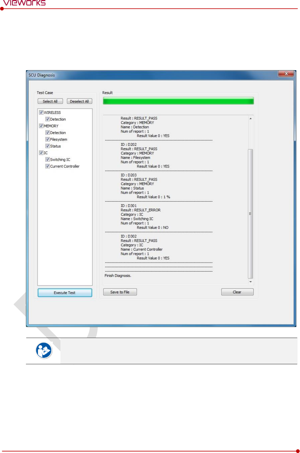
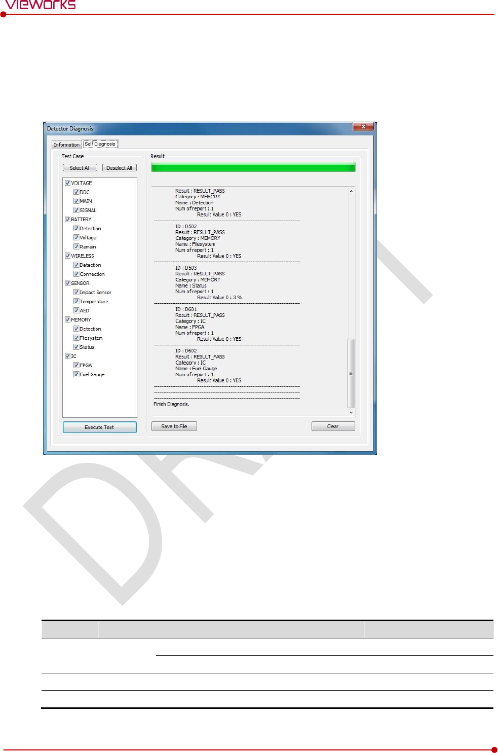
7.3 Self Diagnosis
You can perform self-diagnosis of the detector and SCU from the Self Diagnosis tab of the Diagnosis
dialogue in VIVIX Setup.
1 Choose a desired item to diagnose.
2 Click Execute Test button located at the bottom of the Test Case window.
3 Check the progress and result of diagnosis for each item in the Result window.
4 Click Save to File to save the diagnosis result as a file when the self diagnosis is completed.
7.3.2 Self-Diagnosis Items of Detector and Measures
Voltage
Item
Form
Expected problem
Measures
DDC
Decision
Defective tether interface cable
Change a tether cable.
Poor power supply to the wired operation mode.
Contact a service engineer.
MAIN
Decision
Poor power supply to the processor.
Contact a service engineer.
SIGNAL
Decision
Poor power supply to FPGA.
Contact a service engineer.

Rev.1.0
Page 121 of 151 VW40-153-006
VIVIX-S 1717N User Manual
Battery
Item
Form
Expected problem
Measures
Detection
Decision
The battery is not attached.
Check if a battery is inserted.
A defective ciruit is connected to a battery
pack.
Contact a service engineer.
Voltage
Information
N/A
N/A
Remain
Information
N/A
N/A
Wireless
Item
Form
Expected problem
Measures
Detection
Decision
Defective wireless module
Contact a service engineer.
Connection
Decision
Inconsistent environment of the wireless
communication.
Check obstacles and distance
between a detector and SCU.
Defective wireless module
Contact a service engineer.
Sensor
Item
Form
Expected problem
Measures
Impact Sensor
Decision
Defective shock sensor
Contact a service engineer.
Temperature
Decision
Defective temperature sensor
Contact a service engineer.
AED
Decision
Defective AED sensor
Contact a service engineer.
Memory
Item
Form
Expected problem
Measures
Detection
Decision
Not available to save backup images.
Contact a service engineer.
Not available to save logs.
Contact a service engineer.
The calibration data is inapplicable.
Contact a service engineer.
File system
Decision
Not available to save backup images.
Contact a service engineer.
Not available to save logs.
Contact a service engineer.
Status
Information
N/A
N/A
IC
Item
Form
Expected problem
Measures
FPGA
Decision
Not available to take images from a detector.
Contact a service engineer.
Fuel Gauge
Decision
Not available to check the remaining of a
battery pack.
Contact a service engineer.
Rev.1.0
Page 122 of 151 VW40-153-006
VIVIX-S 1717N User Manual
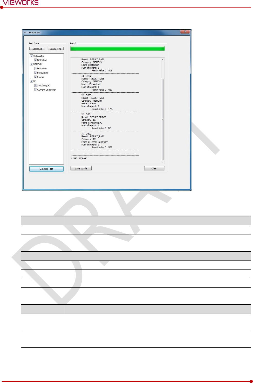
7.3.3 Self-Diagnosis Items of SCU and Measures
Wireless
Item
Form
Expected problem
Measures
Detection
Decision
Defective wireless module
Contact a service eingineer.
Memory
Item
Form
Expected problem
Measures
Detection
Decision
Not available to save logs.
Contact a service eingineer.
File system
Decision
Not available to save logs.
Contact a service eingineer.
Status
Information
N/A
N/A
IC
Item
Form
Expected problem
Measures
Switching IC
Decision
Not available to connect the detector
and PC.
Contact a service eingineer.
Current Controller
Decision
Not available to block overcurrent
when using the wired mode.
Contact a service eingineer.
Rev.1.0
Page 123 of 151 VW40-153-006
VIVIX-S 1717N User Manual
7.4 Cleaning and Disinfection
After using the detector and peripheral equipments for examination, use germicidal disinfecting wipes or
cloth with mild diluted disinfectant detergent to clean surfaces of the product.
Recommended Detergent Foam
Recommended disinfectant wipe
Wip’ anios manufactured by Anios
Sani-cloth Active Wipes by PDI
Recommended disinfectant product
Sulfa’safe
Storage temperature: 5°C ~ 35°C
How to Use Detergent Foam
1 Prepare the disinfectant detergent and a clean and dry non-woven cloth.
2 Use the spray bottle to spray detergent to the cloth and clean the equipment.
3 After it has been cleaned, leave the equipment un-used for 15 minutes.
4 Conduct cleaning once a week or in case of contamination.
Do not re-use wipes.
Be careful to use disinfectant detergent which can cause irritation to eyes and skin.
Use in well-ventilated areas, and wear gloves at all times.
Do not clean the equipment with its power on.
Do not use abrasive brush and scraper to clean the product.
Be careful not to make liquid soak when cleaning battery bay and the connector on the
side of products.
Other Disinfectant detergent compliant to conditions listed below may be used following
proper procedures according to its own manual.
European Biocidal Products designed for surface disinfection (Directive 98/8/EC)
Detergent with composition of Didecyldimethylammonium chloride, polyhexamethylene
biguamide hydrochloride.

Rev.1.0
Page 124 of 151 VW40-153-006
VIVIX-S 1717N User Manual
7.5 Product Initialization
If the connection status of system is not stable or setting value is not correct, user can initialize the
products.
7.5.1 SCU Initialization
1 Click Configuration button of SCU after running the VIVIX Setup program.
2 Click Factory Reset button in Configuration dialogue.
3 Wait for SCU to be initialized and rebooted automatically.
4 Check whether SCU initialization is completed.
Default value of SCU initialization
Item
Default Value
Network
IP Address
169.254.2.100
Subnet Mask
255.255.0.0
Gateway
169.254.2.100
AP
AP On/Off
ON
Frequency
5㎓
Country
KR
Band
40㎒
Channel
+36
SSID
vivix
Key
1234567890
Trigger
Method
Packet
Polarity
Auto

Rev.1.0
Page 125 of 151 VW40-153-006
VIVIX-S 1717N User Manual
7.5.2 Detector Initialization
1 Click Configuration button of Detector after running the VIVIX Setup program.
2 Click Factory Reset button in Configuration dialogue.
3 Wait for Detector to be rebooted automatically.
4 Check whether detector initialization is completed.
Default value of detector initialization
Item
Default Value
Network
IP Address
169.254.1.10
Subnet Mask
255.255.0.0
Gateway
169.254.2.100
WNetwork
SSID
vivix
Key
1234567890
AP Scan
OFF
AP
AP On/Off
OFF
Frequency
5㎓
Country
KR
Band
40㎒
Channel
+36
SSID
vivix_ap
Key
1234567890
Test Pattern Type
20 sec.
Image Timeout Time
Disable
Power Management
Sleep
OFF
Sleep After
10 min.
Shut Down
OFF
Shut Down after
30 min.
Power Control
By Detector
Rev.1.0
Page 126 of 151 VW40-153-006
VIVIX-S 1717N User Manual
7.5.3 Wireless Initialization of Detector
1 Turn off the detector.
2 Press and hold both the power button and AP button over 3 seconds.
3 Initialization will be conducted when orange LED is flickering, after that, the detector will be turned off
automatically.
4 Turn on the detector and check whether detector initialization is completed.
Default value of wireless initialization
Item
Default Value
Network
IP Address
169.254.1.10
Subnet Mask
255.255.0.0
Gateway
169.254.2.100
WNetwork
SSID
vivix
Key
1234567890
Wireless Only
OFF
AP
AP On/Off
OFF
Frequency
5㎓
Country
KR
Band
40㎒
Channel
+36
SSID
vivix_ap
Key
1234567890
When processing the wireless initialization of a detector, only the detector’s network
information is initialized as a default value.
Rev.1.0
Page 127 of 151 VW40-153-006
VIVIX-S 1717N User Manual
7.6 Replacing the Fuse of SCU (SCU Basic only)
There are 2 fuses attached on the standard SCU for the purpose of electrical accident precaution, in case of
over current from external power input. Stop using the SCU immediately when the fuse is blown.
Fuse Information
Item
Specifications
Model
Littelfuse® 218002 (2EA)
Type
Time Lag Cartridge Fuse
Amp Rating
2A
Voltage Rating
250V
Pull the plug out and turn all the devices off before changing the fuse.
First, resolve the cause why the fuse is blown. Replace the fuse to the one provided as an
option (1 set / 2 ea) or to the one with same specifications when the fuse is out.
Be careful not to touch both the patient and the fuse holder at the same time or let the
patient touch the fuse holder.
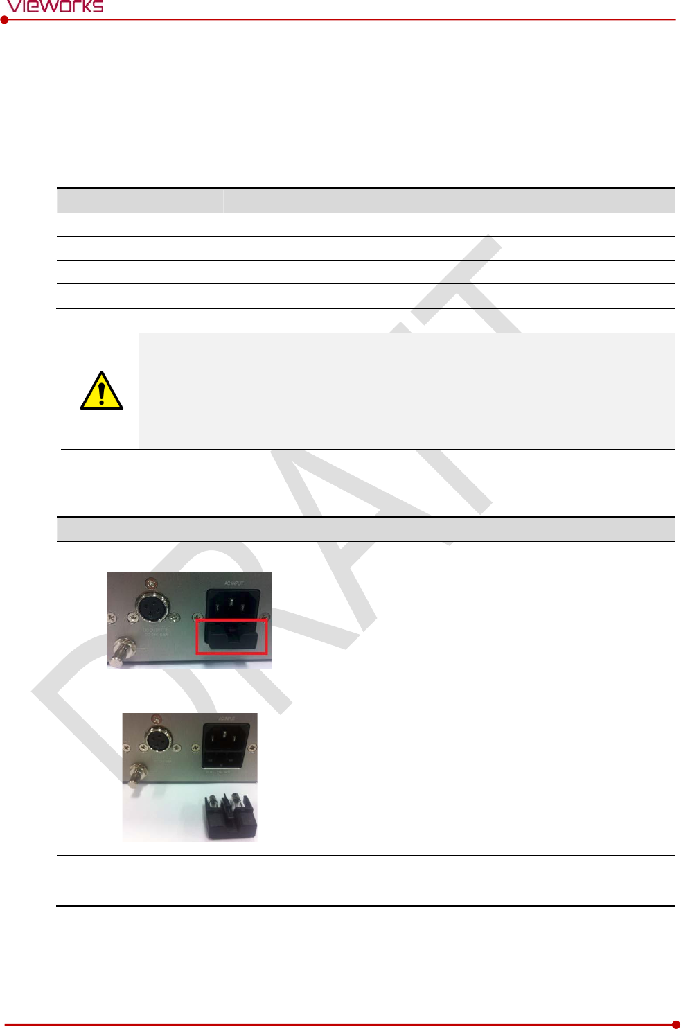
How to Replace the Fuse
No.
Description
1
Separate the fuse from the holder located power input port on
the back side of standard SCU by pulling the fuse holder.
2
After checking, replace the fuse with correct specifications in
case of need.
3
-
Insert the fuse holder again.

Rev.1.0
Page 128 of 151 VW40-153-006
VIVIX-S 1717N User Manual
8. Troubleshooting
This section gives information about troubleshooting.
Troubleshooting

Rev.1.0
Page 129 of 151 VW40-153-006
VIVIX-S 1717N User Manual
8.1 Trobleshooting
8.1.1 Troubleshooting Guide
When you encounter problems while using the equipment, search for the table below for the problem or
error messages and try the solutions.If the problem persists, turn off the detector and consult your sales
representative or a distributor. Please refer to the details of the following symptoms or error messages.
Troubleshooting must be performed by service engineer who is authorized by Vieworks. If
an unqualified person performs troubleshooting on the system resulting in damaging the
detector, software or hardware, then the Vieworks or its representative is not responsible
for the detector repair regardless of remain warranty. For more detailed information, refer
to <10.1 Service Information> and <10.2 Warranty>.
8.1.2 Failed to Turn the Detector On
Symptom
Failed to turn on the power of the detector.
Expected Causes
Not installing a battery pack properly.
Dead battery pack
Battery pack or the detector is broken down.
Solutions
1 Install battery pack
2 Charge battery pack
3 Check the result after getting rid of the battery pack and connecting the tether cable.
4 Replace other battery packs and check the result of it.
5 Replace another detector and check the result of it.
6 Replace corresponding devices.
8.1.3 The Power Switch of SCU or Status LED is not worked
Symptom
The power switch of Basic SCU or SCU mini is not working.
The status LED of SCU is not responding.
Expected Causes
Power cable is broken down.
Errors in the fuse
Internal circuit is broken down.

Rev.1.0
Page 130 of 151 VW40-153-006
VIVIX-S 1717N User Manual
Solutions
1 Check the connection between AC power cable and SCU Basic.
2 Check the connection between DC power cable and SCU mini.
3 Turn off the power switch and turn on again and then check the fan or status of back side.
4 Replace another SCU and check the result of it
5 Replace the fuse of standard SCU. (refer to <7.6 Replacing the Fuse of SCU (SCU Basic only)>)
6 Replace corresponding devices.
8.1.4 Communication Test is failed
Symptom
Transmission error is occurred, failure of communication test is occurred.
Expected Causes
Network connection problem
Network setting problem
PC environment setting problem
Wireless environment environment problem
Devices error
Solutions
1 Check the connection of network cable between Workstation and SCU.
2 Check if the accurate network cable is used or not. (CAT 5E or 6)
3 Set the network information of Workstation, SCU and detector again.
4 Check whole workstation environment again such as firewall setting and release the power save mode.
5 Check surrounding wireless communication environment.
6 Boot up detector and SCU again by processing initialization. (Refer to <7.5 Product Initialization>.)
7 Replace other SCU and Detectors and check the result of it
8 Replace corresponding devices.
8.1.5 The Active LED and Data LED of the Detector are blinking
Symtom
The active LED and data LED is blinking when power LED is ON.
Expected Causes
Detector registeration error
Data transmission error
Solutions
1 Turn on SCU again
2 Check the network cable connection
3 Check the workstation environment and network information again
4 Check if the surrounding wireless communication is good

Rev.1.0
Page 131 of 151 VW40-153-006
VIVIX-S 1717N User Manual
5 Check cable connection again when connected with tether interface cabel
6 Replace other devices and check the result of it
7 Replace corresponding devices.
8.1.6 Errors in Detector LED
Symptom
All LED lamps of detector are blinking.
2 LED lamps of detector are blinking and remaining is blinking slowly.
Expected Causes
Internal hardware errors of the detector.
Solutions
1 Boot up the detector again and check the result of it
2 Replace the detector.
8.1.7 Rapid Consumption of Battery
Symptom
Consumption of fully charged battery pack is fast.
Expected Causes
Performance decrease caused by usage of long time.
Usage of battery pack in low temperature environment.
Solutions
1 Replace to new battery pack if the battery pack has been used for a long time. (Battery pack is
consumables)
2 Use battery pack in room temperature environment. Charging capacity of battery pack in low
temperature environment will be decreasing.
8.1.8 Battery Pack or Installation Part of Battery is Getting Hot
Symptom
Battery pack or compartment for installation of battery pack is getting hot.
Expected Causes
Battery pack failure
Detector Failure
Solutions
1 Do not use battery pack
2 Consult with service engineers of Vieworks.

Rev.1.0
Page 132 of 151 VW40-153-006
VIVIX-S 1717N User Manual
9. Regulatory Information
This section gives explanation about the regulatory information and standard related to the
products
Medical Equipment Safety Standards
Radio Frequency Compliance Information
Labels and Symbols
Guidance and Manufacturer Declaration for EMC
Rev.1.0
Page 133 of 151 VW40-153-006
VIVIX-S 1717N User Manual
9.1 Medical Equipment Safety Standards
9.1.1 Medical Equipment Classification
Item
Description
Type of protection against electrical shock
Class Ⅰ equipment Internally powered
Degree of protection against electrical shock
Type B
Degree of protection against ingress of water
IPX3
Operation mode
Continuous operation
Flammable anesthetics
NOT suitable for use in the presence of a flammable
anesthetic mixture with air or with oxygen or nitrous
oxide.
9.1.2 Product Safety Standard
South Korea
전기, 기계적 안전성에 관한 시험: IEC 60601-1과 식품의약품안전청고시 제 2009-137호에 따른다.
전자파장해방지에 관한 시험: IEC 60601-1-2에 따른다.
전자파 간섭 (EMI)
전자파 전도
식품의약품안전청 고시 2009-54호 1종 A급 기기로서 별표 1의 5.1
식품의약품안전청 고시 2009-54호 별표 1의 전자파장해 (간섭)
전자파 방사
식품의약품안전청 고시 2009-54호 1종 A급 기기로서 별표 1의 5.2
식품의약품안전청 고시 2009-54호 별표 1의 전자파장해(간섭)
전자파 내성 (EMS)
정전기방전(ESD) 시험
식품의약품안전청 고시 2009-54호 별표 2의 36.202/36.202.2/ KN61000-4-2
방사성 RF 전자기장 시험
식품의약품안전청 고시 2009-54호 별표 2의 36.202/36.202.3/ KN61000-4-3
전기적 빠른 과도현상 (EFT)
시험
고시 2009-54호 별표 2의 36.202/36.202.4/ KN61000-4-4
서지(Surge) 시험
고시 2009-54호 별표 2의 36.202/36.202.5/KN61000-4-5
전도성 RF 전자기장 시험
식품의약품안전청 고시 2009-54호 별표 2의 36.202/36.202.6/ KN61000-4-6
전원공급 입력선의 전압 강하,
순간정전 및 전압변동 시험
식품의약품안전청 고시 2009-54호 별표 2의 36.202/36.202.7/KN61000-4-11

Rev.1.0
Page 134 of 151 VW40-153-006
VIVIX-S 1717N User Manual
U.S.A / Canada
Item
IEC 60601-1(ed.2 am1+ am2+ co1)
Medical electrical equipment- Part1: General requirements for safety
UL 60601-1(ed.2)
-
CSA-C22.2 No. 601-1-M90 (R2006)
Medical electrical equipment – Part 1: General requirements for safety
(adopted amendment 2:1995 to IEC60601-1)
IEC 60601-1-2: 2007 (ed.3)
Medical electrical equipment-Part 1-2: Collateral standard:
Electromagnetic compatibility
IEC 60601-1-4: 2000 (ed.1.1)
Medical electrical equipment- Part 1-4: Collateral Standard:
Programmable electrical medical systems
IEC 62304:2006
Medical device software-software life cycle processes
ISO 14971:2012
Medical Device- Application of risk management to medical devices
European Union
Item
MDD (Medical Device Directive)
93/42/EEC as amended by 2007/47/EC
EN ISO 13485:2012
Medical devices – Quality Management systems – Requirements for
regulatory purposes
EN 60601-1: 2007(ed.3)
Medical electrical equipment- Part1: General requirements for safety
IEC 60601-1-2: 2007(ed.3)
Medical electrical equipment-Part 1-2: Collateral Standard :
Electromagnetic compatibility-Requirements and tests
IEC 60601-1-4: 2000(ed.1.1)
Medical electrical equipment- Part 1-4: Collateral Standard :
Programmable electrical medical systems
IEC 62304:2006
Medical device software-Software life cycle processes
ISO 14971: 2012
Medical device – Application of risk management to medical devices.
Rev.1.0
Page 135 of 151 VW40-153-006
VIVIX-S 1717N User Manual
9.2 Radio Frequency Compliance Information
Country
Item
U.S.A
FCC Part 15.107(b) / Part 15.109(b)
FCC Part 15 Subpart E 15.407
FCC Part 15 Subpart C 15.247
European Union
ETSI EN 301 489-1 V1.9.2:2011 (EMC)
ETSI EN 301 489-17 V2.2.1:2012 (EMC)
EN 300 328 V.1.8.1; EN 301 893 V1.7.1 (RF)
EN 62311:2008 (RF Exposure)
South Korea
KS C IEC 60601-1-2:2007
IEC 61000-3-2:2005+A1:2008+A2:2009
IEC 61000-3-3:2008
9.2.1 FCC Compliance
This equipment has been tested and found to comply with the limits for a Class B digital device,
pursuant to part 15 of FCC Rules. These limits are designed to provide reasonable protection against
harmful interference in a residential installation.
Operation is subject to the following tow conditions.
This device may not cause harmful interference.
This device must accept any interference received, including interference that may cause
undesired operation.
This equipment generates, uses, and can radiate radio frequency energy and, if not installed and used
in accordance with the instruction, may cause harmful interference to radio communications. However,
there is no guarantee that interference will not occur in a particular installation. If this equipment does
cause harmful interference to radio or television reception, which can be determined by turning the
equipment off and on, the user is encouraged to try to correct the interference by one or more of the
following measure.
Reorient or relocate the receiving antenna.
Increase the separation between the equipment and receiver.
Connect the equipment into an outlet on a circuit different from where the receiver is connected.
Consult the distributor or an experienced radio/TV technician for help.
Change or modification which is not expressly approved by the party responsible for
compliance could void the user’s authority to operate the equipment.
5.15-5.35G㎐ band is restricted to indoor operations only.
The SAR limit set by the FCC is 1.6 W/kg.
The highest SAR value for this model when tested for use at the front is 0.081 W/kg.
The front side of a detector should be used for image acquisition.

Rev.1.0
Page 136 of 151 VW40-153-006
VIVIX-S 1717N User Manual
9.2.2 FCC SAR
KDB 865664 D01 v01r03
9.2.3 CE R&TTE SAR
Item
EN 62311:2008
Assessment of electronic and electrical equipment related to human exposure
restrictions for electromagnetic fields. (0 Hz - 300 GHz)
EN 62209-1:2006
Human exposure to radio frequency fields from hand-held and body-mounted
wireless communication devices – Human models, instrumentation, and
procedures.
Part 1: Procedure to determine the specific absorption rate (SAR) for hand-held
devices used in close proximity to the ear (frequency range of 300 MHz to 3
GHz).
EN 62209-2:2010
Human Exposure to Radio Frequency Fields from Handheld and Body-Mounted
Wireless Communication Devices – Human models, Instrumentation, and
Procedures.
Part 2: Procedure to determine the specific absorption rate (SAR) for mobile
wireless communication devices used in close proximity to the human body
(frequency range of 300 MHz to 6 GHz).
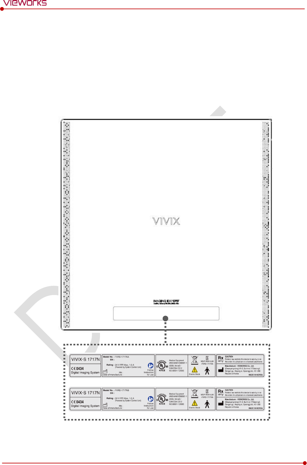
Rev.1.0
Page 137 of 151 VW40-153-006
VIVIX-S 1717N User Manual
9.3 Labels and Symbols
The VIVIX-S 1717N detector and relevant components have labels attached on them. The contents and
locations of each label are indicated below.
9.3.1 Label
VIVIX-S 1717NA / 1717NB (Wired Detector)
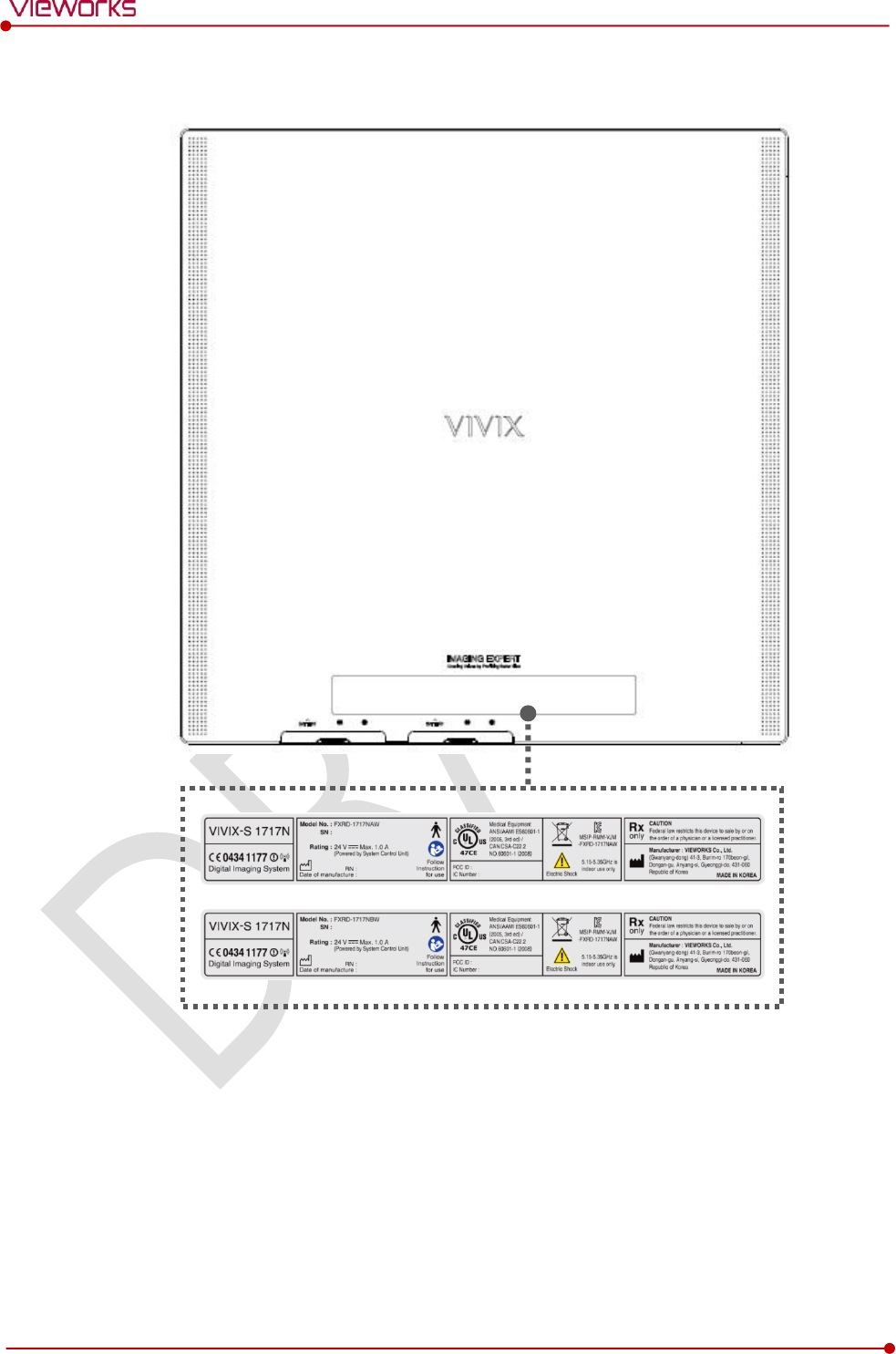
Rev.1.0
Page 138 of 151 VW40-153-006
VIVIX-S 1717N User Manual
VIVIX-S 1717NAW / 1717NBW (Wireless Detector)
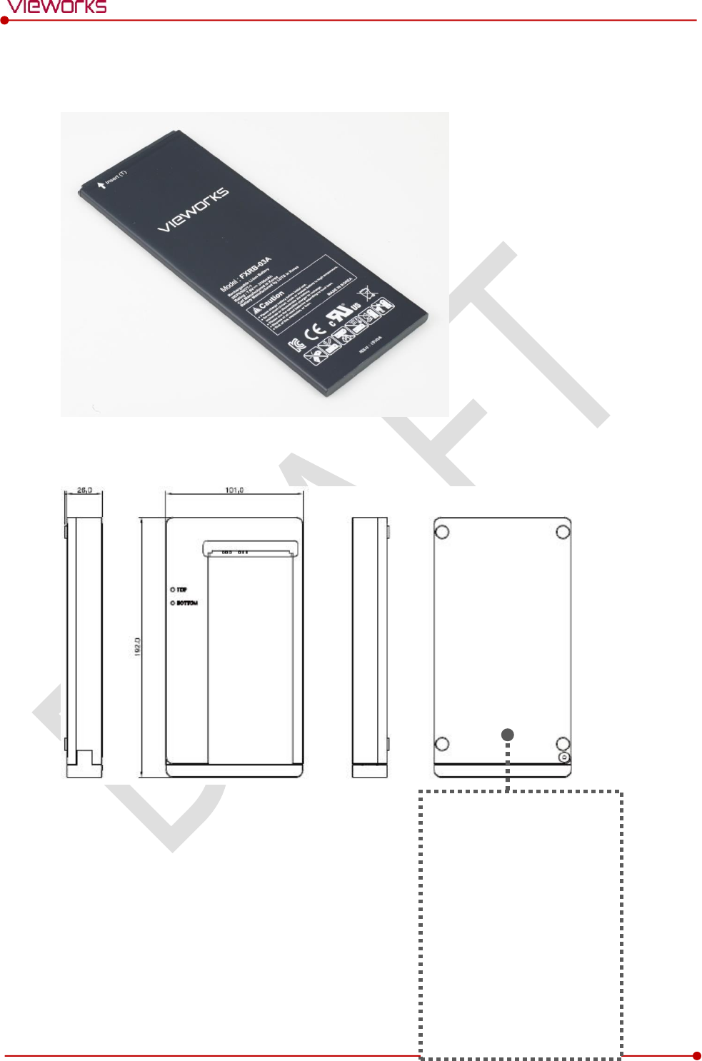
Rev.1.0
Page 139 of 151 VW40-153-006
VIVIX-S 1717N User Manual
Battery
Battery Charger
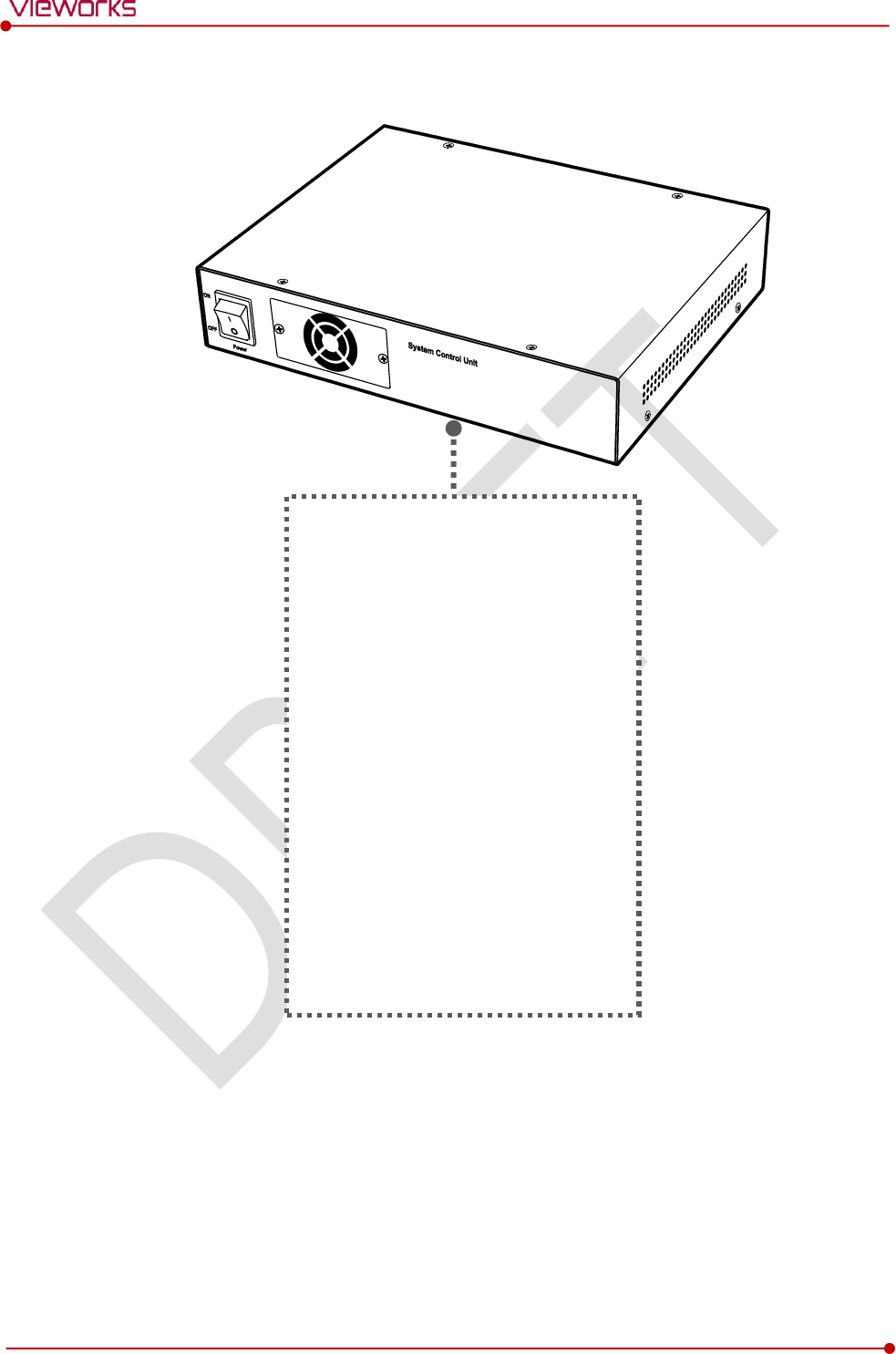
Rev.1.0
Page 140 of 151 VW40-153-006
VIVIX-S 1717N User Manual
SCU Basic (FXRS-02A)
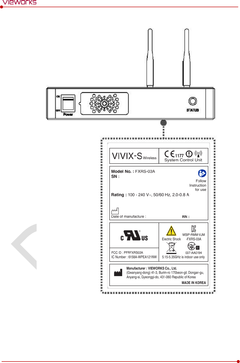
Rev.1.0
Page 141 of 151 VW40-153-006
VIVIX-S 1717N User Manual
SCU Basic (FXRS-03A)
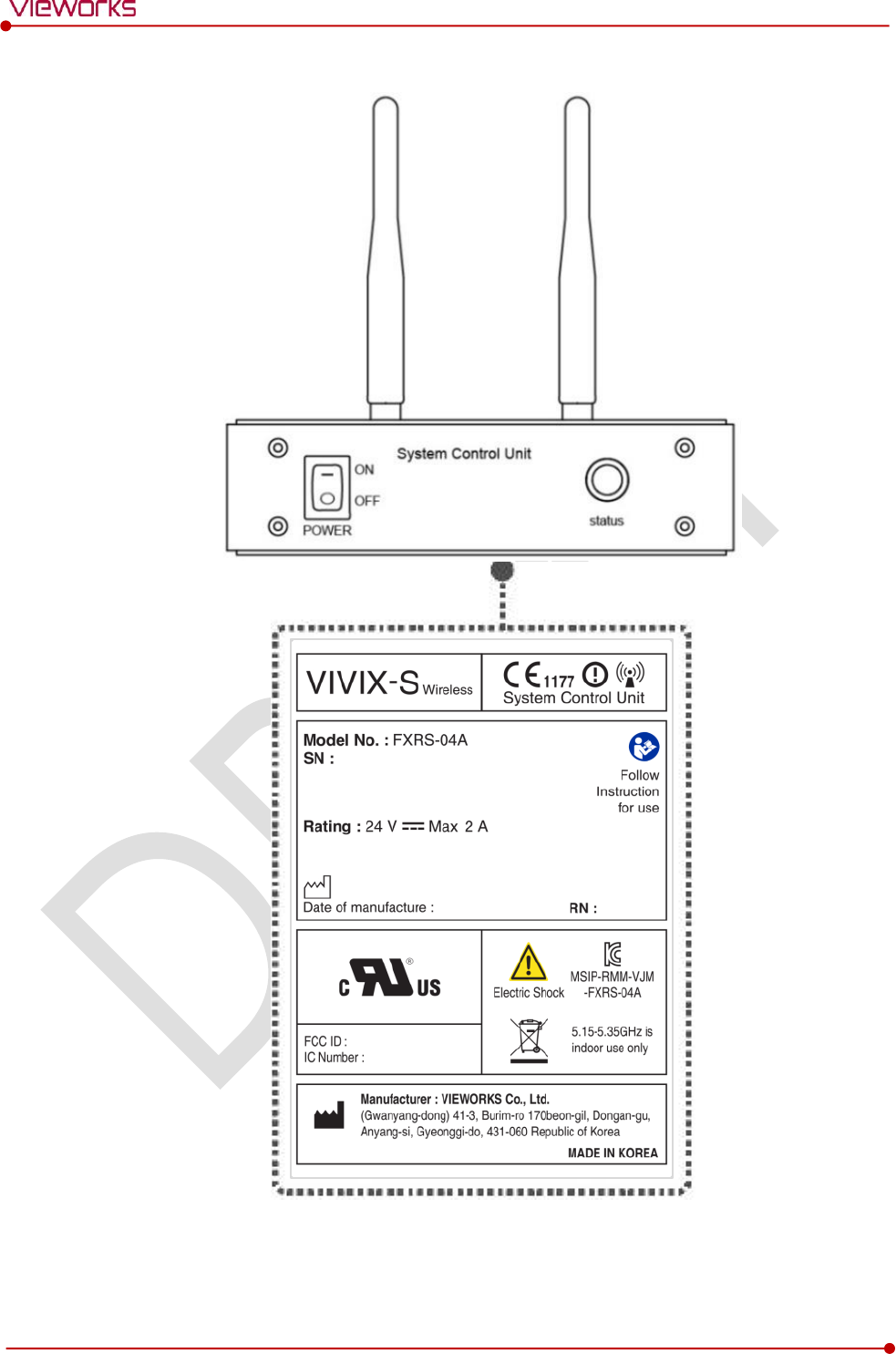
Rev.1.0
Page 142 of 151 VW40-153-006
VIVIX-S 1717N User Manual
SCU mini (FXRS-04A)
Rev.1.0
Page 143 of 151 VW40-153-006
VIVIX-S 1717N User Manual
Outer Box [TBD]
9.3.2 Product Serial Number
Serial Number Composition
The serial numbers for each product or accessory are composed as follows.
V
1
D
A
B
J
0
0
1
Item
Composition
Year
Month
Serial number
Revision will be updated in case of follows.
Mass production or a large amount of order.
Exterior alteration.
Item code will be produced based on internal management standard of vieworks.
Composition code is like follows.
D: Detector
S: SCU
C: Battery Charger
Range of Serial Number is 001 ~ 999.
Initial Per Year
11
12
13
14
15
16
17
18
19
20
AA
AB
AC
AD
AE
AF
AG
AH
AI
BJ
Initial Per Month
1
2
3
4
5
6
7
8
9
10
11
12
A
B
C
D
E
F
U
V
W
X
Y
Z
Composition of Serial Number for Each Item
Model
Composition
Serial Number
1717NA
Detector
VMDAEA001
1717NB
Detector
VNDAEA001
1717NAW
Detector
VODAEA001
1717NBW
Detector
VPDAEA001
FXRC-02A
Battery Charger
VACAEA001
FXRS-02A
SCU
V3SAEA001
FXRS-03A
SCU Basic
VCSAEA001
FXRS-04A
SCU mini
VASAEA001
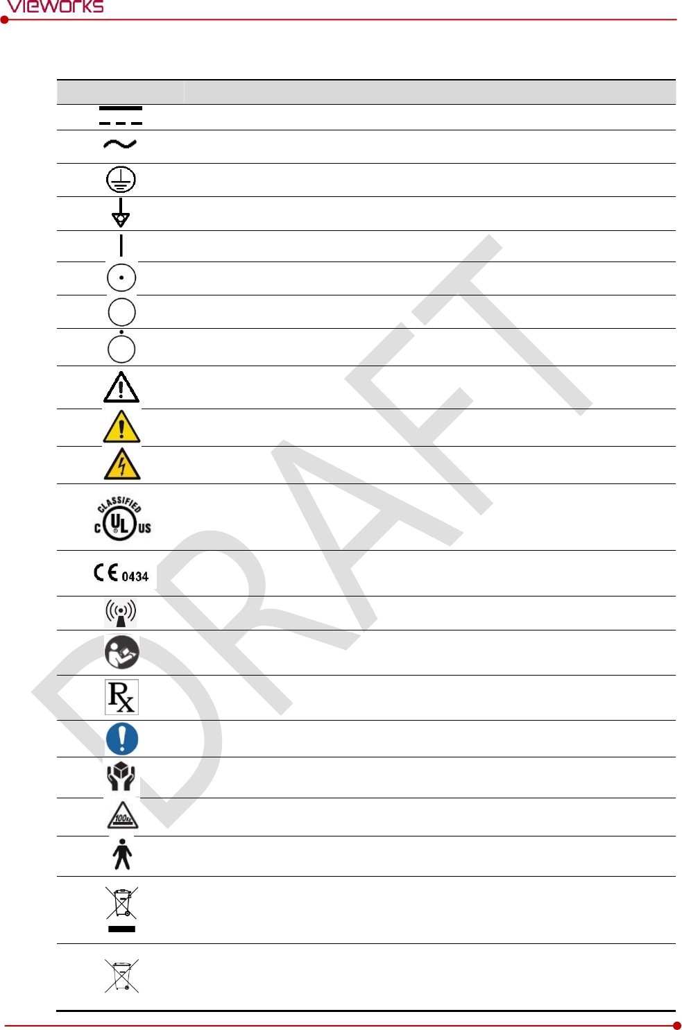
Rev.1.0
Page 144 of 151 VW40-153-006
VIVIX-S 1717N User Manual
9.3.3 Product Symbols
Symbol
Description
Direct current
Alternating current
Protective earth (Ground)
Equipotentiality
Power on
Power on for part of the equipment
Power off
Power off for part of the equipment
Attention, consult accompanying documents
General warning sign
Warning sign for electricity
This Mark shows compliance with both Canadian and U.S. safety requirements. With
Respect to electric shock, fire, and mechanical hazards only. In accordance with
UL60601-1 and CAN/CSA C22.2 No. 601.1.
This mark shows compliance of the essential requirement and other relevant
provisions of Directive 93/42/EEC as amended by 2007/47/EC.
Non-ionizing radiation
Read and understand all instructions and warning labels in the product
documentation before using the equipment. Keep manual for future reference.
Dealing with a medicine that can only be given by a prescription from a doctor and
you should use a certain medication that a doctor recommended.
General mandatory action sign
This mark indicates that this equipment must be handled with care.
Do not jolt or apply excessive load to the equipment.
This is a Type B Applied Part according to UL 60601-1 and EN 60601-1.
This mark indicates that the equipment must be collected separately under the
Directive on Waste Electrical and Electronic Equipment 2002/96/EC (WEEE) in the
European Union. (For European Union)
This mark indicates that the battery must be collected separately under the Directive
on Waste Electrical and Electronic Equipment 2002/96/EC (WEEE) in the European
Union. (For European Union)
Rev.1.0
Page 145 of 151 VW40-153-006
VIVIX-S 1717N User Manual
9.4 Guidance and Manufacturer’s Declaration for EMC
This device has been tested for EMI/EMC compliance, but interference can still occur in an
electromagnetically noisy location. Attempt to maintain a suitable distance between electrical
devices to prevent malfunction.
9.4.1 Electromagnetic Emissions
The Equipment Under Test (EUT) is intended for use in the electromagnetic environment specified below.
The customer or user of the EUT should assure that it is used in such an environment.
Immunity test
Compliance
Electromagnetic Environment
RF Emissions
(CISPR 11)
Group 1
The EUT uses RF energy only for its internal function. Therefore, its
RF emissions are very low and are not likely to cause any
interference in nearby electronic equipment.
RF Emissions
(CISPR 11)
Class B
The EUT is suitable for use in all establishments other than domestic
and those directly connected to the public low-voltage power
supply network that supplies buildings used for domestic purposes.
Harmonic emissions
(IEC 61000-3-2)
Class A
Voltage fluctuations/
Flicker emissions
(IEC 61000-3-3)
Complies
9.4.2 Electromagnetic Immunity
The VIVIX-S 1717N system is intended for using in the electromagnetic environment specified below. The
user of this system should assure that it is used in the following environment.
Electrostatic Discharge (ESD) IEC 61000-4-2
Item
Description
Immunity test
Electrostatic discharge (ESD) IEC 61000-4-2
IEC 60601 test condition
Contact ±6㎸
Air ±8㎸
Compliance Level
Contact ±6㎸
Air ±8㎸
Electromagnetic Environment -
Guidance
Floors should be wood, concrete or ceramic tile.
If floors are covered with synthetic material, the relative humidity
should be at least 30%.
Rev.1.0
Page 146 of 151 VW40-153-006
VIVIX-S 1717N User Manual
Electrical Fast Transient/Burst IEC 61000-4-4
Item
Description
Immunity test
Electrical fast transient/burst IEC 61000-4-4
IEC 60601 test condition
Power supply lines ±2㎸
Input / output lines ±1㎸
Compliance Level
Power supply lines ±2㎸
Input / output lines ±1㎸
Electromagnetic Environment -
Guidance
Main power quality should be that of a typical commercial or hospital
environment.
Surge IEC 61000-4-5
Item
Description
Immunity test
Surge IEC 61000-4-5
IEC 60601 test condition
Differential mode ±1㎸
Common mode ±2㎸
Compliance Level
Differential mode ±1㎸
Common mode ±2㎸
Electromagnetic Environment -
Guidance
Main power quality should be that of a typical commercial or hospital
environment.
Voltage Dips, Short Interruptions/Voltage Variations on Power Supply Input Lines IEC 61000-4-11
Item
Description
Immunity test
Voltage dips, short interruptions and voltage variations on power
supply input lines IEC 61000-4-11
IEC 60601 test condition
<5% Uт (>95% dip in Uт) for 0.5 cycle.
40% Uт (60% dip in Uт) for 5 cycles.
70% Uт (30% dip in Uт) for 25 cycles.
<5% Uт (<95% dip in Uт) for 5 sec.
Compliance Level
<5% Uт (>95% dip in Uт) for 0.5 cycle.
40% Uт (60% dip in Uт) for 5 cycles.
70% Uт (30% dip in Uт) for 25 cycles.
<5% Uт (<95% dip in Uт) for 5 sec.
Electromagnetic Environment -
Guidance
Main power quality should be that of a typical commercial or hospital
environment.
If the user of the EUT image intensifier requires continued operation
during power mains interruptions, it is recommended that the EUT
image intensifier be powered from an uninterruptible power supply or
a battery.
Uт is the AC power prior to approving the test level voltage.
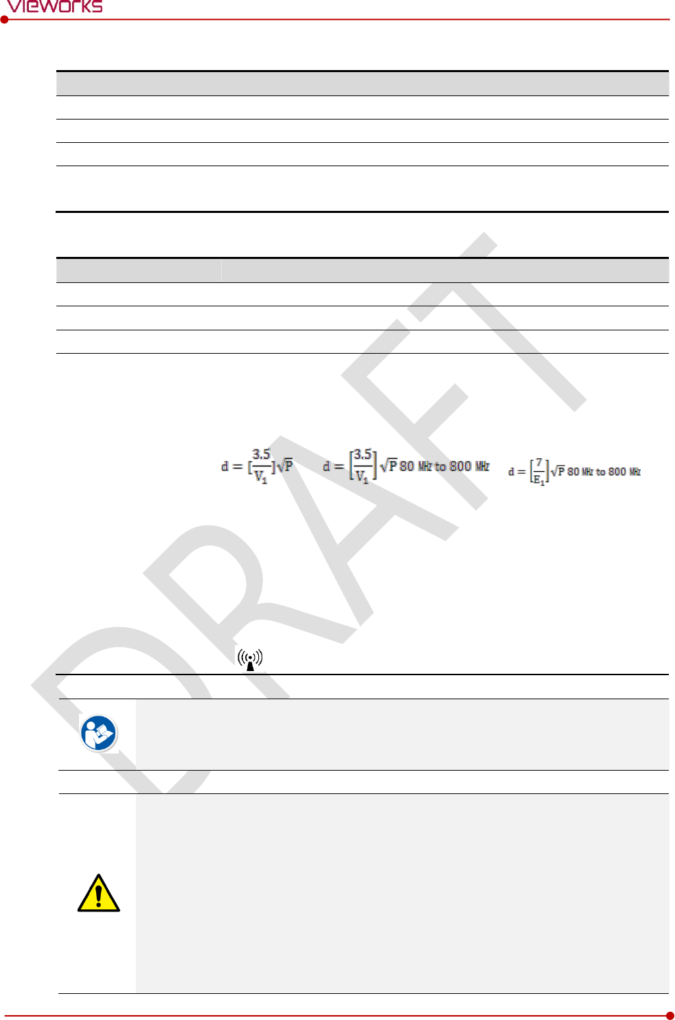
Rev.1.0
Page 147 of 151 VW40-153-006
VIVIX-S 1717N User Manual
Power Frequency (50/60 ㎐) Magnetic Field IEC 61000-4-8
Item
Description
Immunity test
Power frequency (50/60 ㎐) magnetic field IEC 61000-4-8
IEC 60601 test condition
3 A/m
Compliance Level
3 A/m
Electromagnetic Environment -
Guidance
Power frequency magnetic fields should be at levels characteristic of a
typical location in a typical commercial or hospital environment.
Conducted RF IEC 61000-4-6 / Radiated RF IEC 61000-4-3
Item
Description
Immunity test
Conducted RF IEC 61000-4-6
Radiated RF IEC 61000-4-3
IEC 60601 test condition
3 Vrms 150 ㎑ to 80 ㎒
3 V/m 80 ㎒ to 2.5 ㎓
Compliance Level
3 Vrms 150 ㎑ to 80 ㎒
3 V/m 80 ㎒ to 2.5 ㎓
Electromagnetic
Environment - Guidance
Portable and mobile RF communications equipment should be used no
closer to any part of the EUT, including cables, than the recommended
separation distance calculated from the below equations applicable to the
frequency of the transmitter.
P is the maximum output power rating of the transmitter in watts (W)
according to the transmitter manufacturer and d is the recommended
separation distance in meters (m).
Field strengths from fixed RF transmitters, as determined by an
electromagnetic site surveya, should be less than the compliance level in
each frequency range b.
Interference may occur in the vicinity of equipment marked with the symbol.
At 80 ㎒ and 800 ㎒, the higher frequency range applies.
These guidelines may not apply in all situations. Electromagnetic propagation is affected
by absorption and reflection from structures, objects and people.
Field strengths from fixed transmitters, such as base stations for radio (cellular/cordless)
telephones and land mobile radios, amateur radio, AM and FM radio broadcast and TV
broadcast cannot be predicted theoretically with accuracy. To assess the electromagnetic
environment due to fixed RF transmitters, an electromagnetic site survey should be
considered. If the measured field strength in the location in which EUT is used exceeds
the applicable RF compliance level above, EUT should be observed to verify normal
operation. If abnormal performance is observed, additional measures may be necessary,
such as reorienting or relocating EUT.
Over the frequency range 150 ㎑ to 80 ㎒, field strengths should be less than [V1] V/m.

Rev.1.0
Page 148 of 151 VW40-153-006
VIVIX-S 1717N User Manual
10. Information
This section gives overview information for service and warranty of the product.
Service Information
Warranty
Revision History

Rev.1.0
Page 149 of 151 VW40-153-006
VIVIX-S 1717N User Manual
10.1 Service Information
10.1.1 Product Lifetime
The estimated product lifetime may be up to five (5) years under the appropriate regular inspection and
maintenance.
10.1.2 Regular Inspection and Maintenance
In order to ensure the safety of patients, operating personnel and third parties, and to maintain the
performance and reliability of the equipment, be sure to perform regular inspection at least once a year. If
necessary, clean up the equipment, make adjustments, or replace consumables.
There may be cases where overhaul is recommended depending on the conditions. Contact your sales
representative or distributor for regular inspections or maintenance.
10.1.3 Repair
If a problem cannot be solved even after taking the measures indicated in Troubleshooting and contact
your sales representative or a distributor for repairs. Please refer to the name label and provide the
following information.
Model name
FXRD-1717NA / FXRD-1717NB
FXRD-1717NAW / FXRD-1717NBW
Serial number
9 digit-number on the product label
Explanation of problem
Describe as detailed as possible.
10.1.4 Replacement Parts Support
Performance parts (parts required to maintain the functioning of the product) of this product will be
stocked for seven years after discontinuance of production, to allow for repair.
10.1.5 Consumables
The following consumable can deteriorate because of its characteristics and structure. For purchase of
consumables, contact your sales representative or distributor.
Battery pack: FXRB-02A

Rev.1.0
Page 150 of 151 VW40-153-006
VIVIX-S 1717N User Manual
10.2 Warranty
Vieworks warrants that this product will be free from defects in materials and workmanship for a period of
24 months from the date of delivery. If any such product proves defective during this warranty period,
Vieworks at its option, either will repair the defective product without charge for parts and labor, or will
provide a replacement in exchange for the defective product. In order to obtain service under this warranty,
Customer must notify Vieworks of the defect before the expiration of the warranty period and make
suitable arrangements for the performance of service. Customer shall be responsible for packaging and
shipping the defective product to the service center designated by Vieworks with shipping charges prepaid.
Vieworks shall pay for the return of the product to customer if the shipment is to a location within the
country in which Vieworks designated service center is located. Customer shall be responsible for paying all
shipping charges, duties, taxes, and any other charges for products returned to any other locations.
This warranty shall not apply to any defect, failure, or damage caused by improper or inadequate
maintenance and care. Vieworks shall not be obligated to furnish service under this warranty to repair
damage resulting from attempts by personnel other than Vieworks or its representatives to install, repair, or
service this product, to repair damage resulting from improper use or connection to incompatible
equipment or power source; or to service a product that has been modified or integrated with other
products when the effect of such modification or integration increases the time or difficulty of servicing the
product.
THIS WARRANTY IS GIVEN BY VIEWORKS WITH RESPECT TO THIS PRODUCT IN LIEU OF ANY OTHER
WARRANTIES, EXPRESS OR IMPLIED. VIEWORKS AND ITS VENDOR DISCLAIM ANY IMPLIED
WARRANTIES OF MERCHANTABLILITY OR FITNESS FOR A PARTICULAR PURPOSE. VIEWORKS
RESPONSIBILITY TO REPAIR OR REPLACE DEFECTIVE PRODUCTS IS THE SOLE REMEDY PROVIDED TO
THE CUSTOMER FOR BREACH OF THIS WARRANTY. VIEWORKS AND ITS VENDORS WILL NOT BE
LIABLE FOR ANY INDIRECT, SPECIAL, INCIDENTAL, OR CONSEQUENTIAL DAMAGES IRRESPECTIVE OF
WHETHER VIEWORKS OR THE VENDOR HAS ADVANCE NOTICE OF THE POSSIBILITY OF SUCH
DAMAGES.
There are no warranties which extend beyond the description mentioned in this document

Rev.1.0
Page 151 of 151 VW40-153-006
VIVIX-S 1717N User Manual
10.3 Revision History
Version
Date
Descriptions
1.0
2015-03-??
Initial Release
Vieworks Co., Ltd.
(Gwanyang-dong) 41-3, Burim-ro 170beon-gil, Dongan-gu, Anyang-si,
Gyeonggi-do, 431-060 Republic of Korea
Telephone: +82-70-7011-6161
Fax: +82-31-386-8631
Homepage: http://www.vieworks.com
European representative: DONGBANG ACUPRIME
1 Forrest Units, Hennock Road East, Marsh Barton, Exeter EX2 8RU, UK
Telephone: +44(0)-1392-829500
Homepage: http://www.acuprime.com